EP2960599A1 - Cooling a target using electrons - Google Patents
Cooling a target using electrons Download PDFInfo
- Publication number
- EP2960599A1 EP2960599A1 EP15171758.4A EP15171758A EP2960599A1 EP 2960599 A1 EP2960599 A1 EP 2960599A1 EP 15171758 A EP15171758 A EP 15171758A EP 2960599 A1 EP2960599 A1 EP 2960599A1
- Authority
- EP
- European Patent Office
- Prior art keywords
- target
- electrons
- heat sink
- temperature
- leading edge
- Prior art date
- Legal status (The legal status is an assumption and is not a legal conclusion. Google has not performed a legal analysis and makes no representation as to the accuracy of the status listed.)
- Granted
Links
Images


Classifications
-
- G—PHYSICS
- G12—INSTRUMENT DETAILS
- G12B—CONSTRUCTIONAL DETAILS OF INSTRUMENTS, OR COMPARABLE DETAILS OF OTHER APPARATUS, NOT OTHERWISE PROVIDED FOR
- G12B15/00—Cooling
- G12B15/06—Cooling by contact with heat-absorbing or radiating masses, e.g. heat-sink
-
- F—MECHANICAL ENGINEERING; LIGHTING; HEATING; WEAPONS; BLASTING
- F25—REFRIGERATION OR COOLING; COMBINED HEATING AND REFRIGERATION SYSTEMS; HEAT PUMP SYSTEMS; MANUFACTURE OR STORAGE OF ICE; LIQUEFACTION SOLIDIFICATION OF GASES
- F25B—REFRIGERATION MACHINES, PLANTS OR SYSTEMS; COMBINED HEATING AND REFRIGERATION SYSTEMS; HEAT PUMP SYSTEMS
- F25B21/00—Machines, plants or systems, using electric or magnetic effects
-
- B—PERFORMING OPERATIONS; TRANSPORTING
- B64—AIRCRAFT; AVIATION; COSMONAUTICS
- B64D—EQUIPMENT FOR FITTING IN OR TO AIRCRAFT; FLIGHT SUITS; PARACHUTES; ARRANGEMENT OR MOUNTING OF POWER PLANTS OR PROPULSION TRANSMISSIONS IN AIRCRAFT
- B64D43/00—Arrangements or adaptations of instruments
-
- B—PERFORMING OPERATIONS; TRANSPORTING
- B64—AIRCRAFT; AVIATION; COSMONAUTICS
- B64D—EQUIPMENT FOR FITTING IN OR TO AIRCRAFT; FLIGHT SUITS; PARACHUTES; ARRANGEMENT OR MOUNTING OF POWER PLANTS OR PROPULSION TRANSMISSIONS IN AIRCRAFT
- B64D47/00—Equipment not otherwise provided for
-
- F—MECHANICAL ENGINEERING; LIGHTING; HEATING; WEAPONS; BLASTING
- F25—REFRIGERATION OR COOLING; COMBINED HEATING AND REFRIGERATION SYSTEMS; HEAT PUMP SYSTEMS; MANUFACTURE OR STORAGE OF ICE; LIQUEFACTION SOLIDIFICATION OF GASES
- F25B—REFRIGERATION MACHINES, PLANTS OR SYSTEMS; COMBINED HEATING AND REFRIGERATION SYSTEMS; HEAT PUMP SYSTEMS
- F25B2321/00—Details of machines, plants or systems, using electric or magnetic effects
- F25B2321/003—Details of machines, plants or systems, using electric or magnetic effects by using thermionic electron cooling effects
-
- Y—GENERAL TAGGING OF NEW TECHNOLOGICAL DEVELOPMENTS; GENERAL TAGGING OF CROSS-SECTIONAL TECHNOLOGIES SPANNING OVER SEVERAL SECTIONS OF THE IPC; TECHNICAL SUBJECTS COVERED BY FORMER USPC CROSS-REFERENCE ART COLLECTIONS [XRACs] AND DIGESTS
- Y02—TECHNOLOGIES OR APPLICATIONS FOR MITIGATION OR ADAPTATION AGAINST CLIMATE CHANGE
- Y02B—CLIMATE CHANGE MITIGATION TECHNOLOGIES RELATED TO BUILDINGS, e.g. HOUSING, HOUSE APPLIANCES OR RELATED END-USER APPLICATIONS
- Y02B30/00—Energy efficient heating, ventilation or air conditioning [HVAC]
Definitions
- This invention relates generally to thermodynamics, and more particularly to cooling a target using electrons.
- Certain applications may include targets that are heated to a temperature that causes deformation of the material of the target.
- deformation of the target adversely affects performance and efficiency, and may result in failure.
- Targets may be used in various applications where the target is subject to intense heat. For example, as a space shuttle enters Earth's atmosphere at a high speed, the temperature of the space shuttle's wing may increase substantially.
- particle accelerators may be used to manufacture medical isotopes. As the beam current of the particle accelerator on the target feedstock increases, the temperature of the target feedstock also increases. Once the temperature of the target increases to a certain point, the target may deform. Deformation may include, for example, loss of structural integrity, oxidation, charring, or any other form of deformation. Deformation may reduce efficiency (e.g., increased aerodynamic drag), cause failure of the object, and increase material costs.
- a target may be cooled by causing the target to emit electrons, cooling the emitted electrons in a heat sink, and returning the cooled electrons to the target.
- the cooled electrons reduce the temperature of the target without resulting in deformation of the target.
- aspects of the present disclosure include a method that, in one embodiment, impinges a plurality of particles on a target so that electrons are emitted from the target and transports the electrons from the target to a heat sink through a transporting medium.
- the target and the heat sink may be separated by a distance.
- the method further includes cooling the electrons using the heat sink and returning the electrons from the heat sink to the target.
- the present disclosure may provide numerous advantages. For example, using electrons to cool the target may provide a large amount of cooling without resulting in deformation of the target. Since the target is not deformed, the efficiency of the application may be increased. As another example, lower cost materials with low or moderate working temperatures may be used instead of expensive refractory materials because the heating of the target may occur at the surface of the target due to collisions with impinging beams or flows of particles. Since the surface of the target may be the site of the thermionic emission of electrons, the cooling of the target may occur without transporting heat into the bulk of the target. As a result, cheaper materials with low or moderate working temperatures may be used. This cooling technique may work even though the electrically emissive layer may only be a few molecules thick in embodiments.
- material costs may be reduced because deformation may be reduced or eliminated.
- separating the heat sink and the target by a distance may allow for the electrons to cool during the transportation of those electrons.
- electrons since electrons are emitted from the target and returned to the target in a closed loop, there is not a capacity limitation because electrons are not depleted.
- cooling a target feedstock using electrons may allow for faster manufacture of medical isotopes because the beam current of a particle accelerator may be increased without deforming the target feedstock.
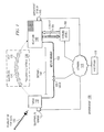
- FIGURE 1 illustrates an example environment 100 in which electrons 120 of target 110 are cooled.
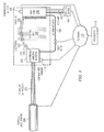
- FIGURES 2-2A and 3 show example embodiments in which target 110 of FIGURE 1 may be a leading edge of wing 210 of aerial vehicle 204 and electrically emissive material 310, respectively.
- FIGURE 4 shows an example method for cooling target 110 of FIGURE 1 using electrons.
- FIGURE 1 is a diagram illustrating an example environment 100 in which electrons 120 of target 110 are cooled, according to certain embodiments of the present disclosure.
- Environment 100 may include plurality of particles 105, target 110, temperature sensor 115, electrons 120, transporting medium 130, heat 135, heat sink 140, temperature sensor 145, distance 147, return member 150, valve 155, cooling device 160, coolant 165, processor 170, and network 175.
- plurality of particles 105 may be impinged on target 110, causing the temperature of target 110 to increase such that target 110 emits electrons 120.
- target 110 may emit electrons 120 exponentially.
- Electrons 120 may carry heat away from target 110 to heat sink 140 through transporting medium 130.
- Electrons 120 may disburse or reject heat 135 into transporting medium 130.
- Heat sink 140 may cool electrons 120 and return the cooled electrons 120 to target 110 using return member 150. As a result of returning the cooled electrons 120 to target 110, the temperature of target 110 may be reduced without deforming target 110.
- Such a cooling technique may provide substantial cooling of target 110, increase the efficiency of applications employing this cooling technique, and decrease material costs. Each component of environment 100 is discussed below.
- Plurality of particles 105 may be any beam or flow of particles in certain embodiments.
- plurality of particles 105 may be air.
- the air may be impinged on the leading edge of an aerial vehicle.
- plurality of particles 105 may be a plurality of protons.
- the plurality of protons may be emitted from a particle accelerator.
- Plurality of particles 105 may be directed towards target 110 in certain embodiments.
- plurality of particles 105 may be air that impinges on the leading edge of an aerial vehicle.
- plurality of particles 105 may be a plurality of protons emitted from a particle accelerator towards an electrically emissive material.
- Plurality of particles 105 may cause the temperature of target 110 to increase such that target 110 emits electrons 120 in certain embodiments.
- the temperature of the leading edge of the wing may increase such that the leading edge emits electrons 120.
- a particle accelerator may impinge a plurality of protons on an electrically emissive material (e.g., to produce a medical isotope, such as technetium 99m), thereby increasing the temperature of the electrically emissive material such that the electrically emissive material emits electrons 120.
- an electrically emissive material e.g., to produce a medical isotope, such as technetium 99m
- Target 110 may be any object that includes electrons 120 in certain embodiments.
- target 110 may be the leading edge of an aerial vehicle.
- target 110 may be an electrically emissive material, such as molybdenum or technetium 99m.
- Target 110 may be coupled to temperature sensor 115 and/or return member 150 in certain embodiments.
- target 110 may have a cross-sectional area less than a cross-sectional area of heat sink 140. Due to plurality of particles 105 impinging on target 110, the temperature of target 110 may increase such that target 110 emits electrons 120 in certain embodiments. For example, where target 110 is the leading edge of an aerial vehicle, the temperature of that leading edge may heat up significantly as the aerial vehicle travels at high speeds. As the temperature of the leading edge increases, the leading edge may emit electrons 120. When the temperature of the leading edge reaches the thermionic emission threshold of the leading edge, the leading edge may emit electrons 120 exponentially.
- Temperature sensor 115 may be any sensor configured to measure a temperature of target 110 in certain embodiments.
- temperature sensor 115 may be a thermometer, a thermocouple, or any other sensor configured to measure the temperature of target 110.
- Temperature sensor 115 may be coupled to target 110 in any manner in some embodiments.
- Temperature sensor 115 may be coupled to network 175 in any manner (e.g., wired or wireless) in certain embodiments.
- Temperature sensor 115 may transmit temperature measurements of target 110 to processor 170 through network 175.
- Processor 170 may use those measurements to determine whether to adjust a rate of flow of coolant 165 from cooling device 160 to heat sink 140 in some embodiments.
- Processor 170 may use temperature measurements of target 110 to adjust valve 155. For example, processor 170 may determine that the temperature of target 110 is too high and open valve 155 to allow for more cooling electrons 120 to return to target 110 through return member 150.
- Electrons 120 may be any electrons of target 110 in certain embodiments. Electrons 120 may be free electrons in an embodiment. That is, electrons 120 may not be bound to other molecules. Electrons 120 may be emitted from target 110 as the temperature of target 110 increases. When the temperature of target 110 reaches the thermionic emission threshold of target 110, the emission of electrons 120 increases exponentially. As electrons 120 are emitted, each electron carries heat away from target 110. In some embodiments, electrons 120 may travel from target 110 to heat sink 140 through transporting medium 130. Electrons 120 may be cooled in heat sink 140 in certain embodiments. Electrons 120 may also be cooled during transportation through transporting medium 130. For example, electrons 120 may reject heat 135 into transporting medium 130.
- the cooled electrons 120 may be returned to target 110 through return member 150 in a closed loop (i.e., recirculated).
- return member 150 may be used to cool target 110.
- any type of fermion may be used.
- muons may be used.
- Transporting medium 130 may be any medium capable of transporting electrons 120 in certain embodiments.
- transporting medium 130 may be air.
- transporting medium 130 may be a vacuum.
- transporting medium 130 may include a conductive medium of ionized plasma.
- the conductive medium of ionized plasma may be formed as a shockwave travels off of the front of an aerial vehicle.
- electrons 120 may be cooled.
- electrons 120 may disburse or reject heat 135 into transporting medium 130.
- Transporting medium 130 may transport electrons 120 from target 110 to heat sink 140.
- Heat 135 may be any heat of electrons 120 that may be disbursed or rejected into transporting medium 130 as electrons 120 are transported from target 110 to heat sink 140 in an embodiment. Heat 135 may be disbursed or rejected via radiation or conduction (e.g., conductive collisions) in an embodiment.
- Heat sink 140 may be any device configured to capture and cool electrons 120.
- heat sink 140 may be a structure with a plurality of fins extending vertically from a base.
- Heat sink 140 may be any type of heat sink, such as a pin heat sink, a straight heat sink, or a flared heat sink.
- Heat sink 140 may be a radiator in an embodiment.
- Heat sink 140 may capture emitted electrons 120 from transporting medium 130 in some embodiments.
- heat sink 140 may be positively charged such that the emitted electrons 120, which are negatively charged, are attracted to heat sink 140.
- heat sink 140 may cool electrons 120 by dissipating heat into a surrounding area.
- Heat sink 140 may be separated from target 110 by distance 147, which may allow electrons 120 to cool in transporting medium 130 prior to being cooled in heat sink 140.
- Heat sink 140 may be coupled to temperature sensor 145 and/or return member 150 in any manner in certain embodiments.
- Heat sink 140 may also be in fluid communication with cooling device 160.
- heat sink 140 may receive coolant 165 from cooling device 160.
- coolant 165 may cool heat sink 140 as its temperature increases due to receiving electrons 120 from target 110.
- heat sink 140 may have a cross-sectional area that is greater than a cross-sectional area of target 110.
- a ratio of a cross-sectional area of heat sink 140 to a cross-sectional area of target 110 may be greater than one.
- providing a ratio of a cross-sectional area of heat sink 140 to a cross-sectional area of target 110 greater than one may provide for greater heat transfer from target 110 to heat sink 140.
- Temperature sensor 145 may be any sensor configured to measure a temperature of heat sink 140 in certain embodiments.
- temperature sensor 145 may be a thermometer, a thermocouple, or any other sensor configured to measure the temperature of heat sink 140.
- Temperature sensor 145 may be coupled to heat sink 140 in any manner in some embodiments.
- Temperature sensor 145 may be coupled to network 175 in any manner (e.g., wired or wireless) in certain embodiments.
- Temperature sensor 145 may transmit temperature measurements of heat sink 140 to processor 170 through network 175. Processor 170 may use those measurements to adjust a rate of flow of coolant 165 from cooling device 160 to heat sink 140 in some embodiments.
- Distance 147 may be any distance that separates target 110 from heat sink 140 in certain embodiments.
- distance 147 may be the distance between a leading edge of an aircraft and a rear portion of the aircraft where heat sink 140 may be positioned in some embodiments.
- distance 147 may be any non-zero distance such that target 110 and heat sink 140 are not adjacent. Separating heat sink 140 and target 110 using distance 147 may allow electrons 120 to cool in transporting medium 130.
- Distance 147 may be any distance.
- distance 147 may be six inches.
- distance 147 may be six feet.
- Return member 150 may be any device configured to transport electrons 120 in certain embodiments. Return member 150 transports cooled electrons 120 from heat sink 140 to target 110 such that cooled electrons 120 are returned to target 110 in an embodiment. Return member 150 may be a wire in some embodiments. Return member 150 may be coupled to heat sink 140 and/or target 110 in an embodiment. Return member 150 may include valve 155 in an embodiment.
- Valve 155 may be any type of controllable valve in an embodiment.
- valve 155 may be a silicone control rectifier.
- valve 155 may be a field effect transistor.
- Valve 155 may be coupled to return member 150 in an embodiment.
- Valve 155 may be coupled to processor 170 via network 175 in an embodiment.
- Valve 155, through signals received from processor 170 via network 175, may control the flow of electrons 120 through return member 150 in an embodiment.
- valve 155 may receive signals from processor 170 via network 175 instructing valve 155 to open or close (partially or fully).
- valve 155 may receive a signal from processor 170 via network 175 instructing valve 155 to increase its opening to allow more cooling electrons 120 through return member 150. Allowing more cooling electrons 120 to return to target 110 may decrease the temperature of target 110. As the temperature of target 110 decreases to a certain range or point, valve 155 may receive a signal from processor 170 via network 175 instructing valve 155 to decrease its opening to allow fewer cooling electrons 120 through return member 150. Allowing fewer cooling electrons 120 to return to target 110 may increase the temperature of target 110. By controlling the flow of electrons 120, valve 155 (via signals received from processor 170) may control the temperature of target 110 so that target 110 maintains a constant temperature below the maximum working temperature of target 110. Maintaining such a temperature may prevent target 110 from deforming.
- Cooling device 160 may be any device configured to cool heat sink 140 in certain embodiments.
- cooling device 160 may be a pump that pumps coolant 165 through heat sink 140.
- Cooling device 160 may be in fluid communication with heat sink 140.
- cooling device 160 may apply coolant 165 to heat sink 140.
- cooling device 160 may receive coolant 165 back from heat sink 140.
- Cooling device 160 may be coupled to network 175 in an embodiment.
- Cooling device 160 may be controlled by processor 170 through network 175 in some embodiments.
- cooling device 160 may receive a signal from processor 170 through network 175 directing cooling device 160 to change a rate of fluid flow of coolant 165 into heat sink 140.
- cooling device 160 may be instructed to change a rate of flow of coolant 165 based on temperature readings from temperature sensor 115 and/or temperature sensor 145.
- Coolant 165 may be any fluid or gas used to cool heat sink 140 in an embodiment.
- coolant 165 may be water.
- coolant 165 may be a refrigerant.
- coolant 165 may be fuel.
- Coolant 165 may be transported from cooling device 160 to heat sink 140 and returned from heat sink 140 to cooling device 160 in certain embodiments. As a result of coolant 165 being applied to heat sink 140, coolant 165 may carry heat away from heat sink 140 thereby cooling heat sink 140.
- Processor 170 may control the operation of temperature sensor 115, temperature sensor 145, valve 155, and/or cooling device 160 by processing data received through network 175 and sending signals through network 175 in certain embodiments.
- Processor 170 may control the operation of particle accelerator 304 (discussed below) in some embodiments.
- Processor 170 may receive temperature measurements from temperature sensor 115 and/or temperature sensor 145 either directly or through network 175 in certain embodiments. Based on the temperature measurements from temperature sensor 115 and/or temperature sensor 145, processor 170 may determine whether to adjust a rate of flow of coolant 165 from cooling device 160 to heat sink 140 in an embodiment. For example, as the temperature measurement from temperature sensor 145 increases, processor 170 may determine to increase a rate of coolant 165.
- Processor 170 may regulate the temperature of target 110 by controlling the flow of electrons 120 through valve 155 in an embodiment. For example, processor 170 may adjust the opening or closing of valve 155 based on temperature measurements from temperature sensor 115 indicating the temperature of target 110. As the temperature measurements of target 110 increase, processor 170 may send a signal to valve 155 via network 175 instructing valve 155 to increase its opening to allow more cooling electrons 120 to return to target 110. As the temperature measurements of target 110 decrease, processor 170 may send a signal to valve 155 via network 175 instructing valve 155 to decrease its opening to allow fewer cooling electrons 120 to return to target 110. Processor 170 may determine those adjustments in any manner.
- processor 170 may compare the temperature measurements of target 110 to a threshold value and adjust valve 155 if the measurements are within a certain percentage of the threshold value (e.g., 10%, 20%, 30%, or any other percentage). By controlling valve 155, processor 170 may control the temperature of target 110 so that the temperature remains constant. Additionally, controlling valve 155 may allow processor 170 to maintain the temperature of target 110 below the maximum working temperature of target 110, which may prevent target 110 from deforming. Controlling valve 155 may also allow processor 170 to prevent the temperature of target 110 from dropping too much. For example, processor 170 may decrease the flow of electrons 120 to prevent the temperature of target 110 from dropping to a temperature range where the material of target 110 may crack.
- a certain percentage of the threshold value e.g. 10%, 20%, 30%, or any other percentage.
- Processor 170 includes any hardware and/or software that operates to control and process information.
- processor 170 may execute logic to control the operation of cooling device 160 and/or particle accelerator 304.
- Processor 170 may be a programmable logic device, a microcontroller, a microprocessor, any suitable processing device, or any suitable combination of the preceding.
- Network 175 may be any suitable network operable to facilitate communication between temperature sensor 115, temperature sensor 145, valve 155, cooling device 160, and processor 170. In some embodiments, network 175 may be operable to facilitate communication between particle accelerator 304 and processor 170. Network 175 may include any interconnecting system capable of transmitting electrical signals, data, messages, or any combination of the preceding.
- Network 175 may include all or a portion of a public or private data network, a local area network (LAN), a metropolitan area network (MAN), a wide area network (WAN), a local, regional, or global communication or computer network, such as the Internet, a wireline or wireless network, an enterprise intranet, or any other suitable communication link, including combinations thereof, operable to facilitate communication between temperature sensor 115, temperature sensor 145, valve 155, cooling device 160, processor 170, and/or particle accelerator 304.
- LAN local area network
- MAN metropolitan area network
- WAN wide area network
- a local, regional, or global communication or computer network such as the Internet
- wireline or wireless network such as the Internet
- an enterprise intranet such as the Internet
- any other suitable communication link including combinations thereof, operable to facilitate communication between temperature sensor 115, temperature sensor 145, valve 155, cooling device 160, processor 170, and/or particle accelerator 304.
- plurality of particles 105 may be impinged on target 110.
- target 110 emits electrons 120.
- Electrons 120 may be transported from target 110 to heat sink 140 through transporting medium 130.
- Heat sink 140 may cool electrons 120 and return cooled electrons 120 to target 110 using return member 150. As the cooled electrons 120 are returned to target 110, the temperature of target 110 may decrease.
- FIGURE 2 illustrates an example embodiment where target 110 of FIGURE 1 may be leading edge of wing 210 on aerial vehicle 204
- FIGURE 2A illustrates an enlarged detail view of a portion of aerial vehicle 204
- FIGURE 3 illustrates an example embodiment where target 110 of FIGURE 1 may be electrically emissive material 310.
- FIGURES 2-2A and FIGURE 3 illustrate many components from FIGURE 1 , those components will not be discussed again with respect to FIGURES 2-2A and FIGURE 3 .
- FIGURE 2 is a diagram illustrating an example embodiment in which target 110 of FIGURE 1 may be leading edge of wing 210 of aerial vehicle 204, according to certain embodiments of the present disclosure.
- target 110 of FIGURE 1 may be leading edge of wing 210 and plurality of particles 105 may be air 205.
- Aerial vehicle 204 may be any vehicle configured to travel through air 205 in an embodiment.
- aerial vehicle 204 may be a scram jet.
- aerial vehicle 204 may be a jet.
- aerial vehicle 204 may be a space vehicle, such as a space shuttle.
- Aerial vehicle 204 may include heat sink 140 separated from a leading edge of wing 210 by distance 147.
- heat sink 140 may be positioned towards the rear of aerial vehicle 204.
- heat sink 140 may be positioned at the rear of a wing of aerial vehicle 204. In that manner, as aerial vehicle 204 travels through air 205, air 205 forces electrons 120 emitted from leading edge of wing 210 towards heat sink 140 in the rear of aerial vehicle 204.
- Air 205 may be any portion of an atmosphere in an embodiment.
- air 205 may be a portion of Earth's atmosphere.
- Air 205 may be impinged on leading edge of wing 210 thereby causing the temperature of leading edge of wing 210 to increase.
- Leading edge of wing 210 may be a portion of a wing of aerial vehicle 204 that is the foremost edge of the wing in an embodiment.
- Leading edge of wing 210 may include electrons 120.
- Leading edge of wing 210 may be any shape.
- leading edge of wing 210 may be straight.
- leading edge of wing 210 may be curved.
- Leading edge of wing 210 may be swept in some embodiments.
- Leading edge of wing 210 may be unswept in certain embodiments.
- Leading edge of wing 210 may be made of any material.
- leading edge of wing 210 may be made of aluminum.
- leading edge of wing 210 As leading edge of wing 210 is impinged with air 205, the temperature of leading edge of wing 210 may increase such that leading edge of wing 210 emits electrons 120. As noted above, when the temperature of leading edge of wing 210 reaches the thermionic emission point of leading edge of wing 210, the emission of electrons 120 increases exponentially.
- aerial vehicle 204 may be travelling at extremely high speeds through air 205.
- aerial vehicle 204 may travel at Mach 5 speed.
- aerial vehicle 204 may travel at Mach 6 speed.
- air 205 impinges on leading edge of wing 210, the temperature of leading edge of wing 210 increases. The temperature of leading edge of wing 210 may increase such that electrons 120 are emitted from leading edge of wing 210. Electrons 120 each carry away heat 135 from leading edge of wing 210. Since aerial vehicle 204 may be travelling at high speeds through air 205, air 205 pushes the emitted electrons 120 from leading edge of wing 210 to heat sink 140 positioned behind leading edge of wing 210.
- Heat sink 140 captures the emitted electrons 120. Heat sink 140 cools electrons 120 and returns the cooled electrons 120 back to leading edge of wing 210 through return member 150. As a result of returning cooled electrons 120 to leading edge of wing 210, leading edge of wing 210 may be cooled. Cooling leading edge of wing 210 by cooling electrons 120 emitted from leading edge of wing 210 provides significant cooling capability without deforming leading edge of wing 210.
- FIGURE 3 is a diagram illustrating an example embodiment in which target 110 of FIGURE 1 may be electrically emissive material 310, according to certain embodiments of the present disclosure.
- plurality of particles 105 may be a plurality of protons 305 and target 110 may be electrically emissive material 310.
- particle accelerator 304 may emit plurality of protons 305, which are impinged on electrically emissive material 310.
- electrically emissive material 310 increases in temperature, electrically emissive material 310 may emit electrons 120, which travel across vacuum 325 to heat sink 140 through electric field 330. Heat sink 140 may cool electrons 120 and return the cooled electrons to electrically emissive material 310.
- Particle accelerator 304 may be any device configured to impinge protons 305 on electrically emissive material 310.
- particle accelerator 304 may be a cyclotron.
- Particle accelerator 304 may be coupled to processor 170 through network 175 in an embodiment.
- processor 170 may transmit a signal to particle accelerator 304 through network 175 to adjust the beam current of particle accelerator 304.
- Plurality of protons 305 may be any beam of protons in an embodiment.
- Protons 305 may be emitted from particle accelerator 304 in an embodiment.
- Protons 305 may impinge on electrically emissive material 310 in an embodiment. As a result of that impingement, electrically emissive material 310 may increase in temperature.
- Electrically emissive material 310 may be any type of chemically inert material that is not subject to oxidation in an embodiment.
- electrically emissive material 310 may include molybdenum.
- electrically emissive material 310 may be a mayenite electride (calcium aluminate).
- Electrically emissive material 310 may be any type of electride in an embodiment.
- electrically emissive material 310 may be the target feedstock for a medical isotope.
- electrically emissive material 310 may be a ceramic electride.
- electrically emissive material 310 may be aluminum. Electrically emissive material 310 may include electrons 120 in an embodiment.
- electrically emissive material 310 may emit electrons 120.
- electrically emissive material 310 may emit electrons 120 exponentially.
- Vacuum 325 may be any space where the pressure is lower than atmospheric pressure.
- vacuum 325 may be a space that is devoid of matter.
- vacuum 325 may be a partial vacuum.
- Vacuum 325 may include electric field 330 in certain embodiments.
- electric field 330 may pull electrons 120 through vacuum 325 from electrically emissive material 310 to heat sink 140.
- Electric field 330 may be any component of an electromagnetic field in an embodiment. Electric field 330 may facilitate the transportation of emitted electrons 120 to heat sink 140 through vacuum 325 in an embodiment. Electric field 330 may arise artificially or naturally. For example, electric field 330 may be artificially created by applying a voltage potential between electrically emissive material 310 and heat sink 140. As another example, electric field 330 may arise naturally as a result of differences in charge between the point where electrons 120 are emitted (i.e., target 110) and the point where electrons 120 are collected (i.e., heat sink 140).
- particle accelerator 304 may impinge protons 305 on electrically emissive material 310, causing the temperature of electrically emissive material 310 to increase.
- the temperature of electrically emissive material 310 may increase such that electrically emissive material 310 emits electrons 120.
- Electrons 120 may carry heat away from electrically emissive material 310. Electrons 120 may be pulled towards heat sink 140 through vacuum 325 using electric field 330. Heat sink 140 may capture electrons 120 and cool electrons 120. Heat sink 140 may return the cooled electrons 120 to electrically emissive material 310 using return member 150. Returning the cooled electrons 120 to electrically emissive material 310 may decrease the temperature of electrically emissive material 310. Accordingly, returning the cooled electrons 120 provides significant cooling of electrically emissive material 310 without deforming electrically emissive material 310.
- FIGURE 4 is a flow chart illustrating an example method 400 for cooling target 110 of FIGURE 1 , according to certain embodiments of the present disclosure.
- Method 400 begins at step 410, where plurality of particles 105 may be impinged on target 110 such that electrons 120 are emitted from target 110.
- plurality of particles 105 may be air 205 that is impinged on leading edge of wing 210 of aerial vehicle 204.
- plurality of particles 105 may be protons 305 emitted from particle accelerator 304 and impinged on electrically emissive material 310.
- electrons 120 may be transported from target 110 to heat sink 140.
- electrons 120 may be emitted from leading edge of wing 210 and transported to heat sink 140 through transporting medium 130.
- electrons 120 may be emitted from electrically emissive material 310 and transported from electrically emissive material 310 to heat sink 140 through electric field 330 of vacuum 325.
- target 110 and heat sink 140 may be separated by distance 147.
- electrons 120 may be cooled using heat sink 140. As noted above, electrons 120 may carry heat away from target 110. As electrons 120 are passed through heat sink 140, electrons 120 may be cooled.
- electrons 120 may be returned from heat sink 140 to target 110.
- cooled electrons 120 may be returned from heat sink 140 to leading edge of wing 210 of aerial vehicle 204.
- cooled electrons 120 may be returned from heat sink 140 to electrically emissive material 310.
- cooled electrons 120 are returned from heat sink 140 to target 110 using return member 150.
- plurality of particles 105 may be impinged on target 110, causing the temperature of target 110 to increase.
- the temperature of target 110 may increase such that target 110 emits electrons 120.
- Electrons 120 may carry heat away from target 110.
- Electrons 120 may be transported across transporting medium 130 to heat sink 140, where electrons 120 are cooled.
- the cooled electrons 120 are returned to target 110 using return member 150. Returning cooled electrons 120 to target 110 decreases the temperature of target 110 without deforming target 110.
- the present disclosure may provide numerous advantages. For example, using electrons 120 to cool target 110 may provide a large amount of cooling without resulting in deformation of target 110. As another example, since deformation is reduced or eliminated, material costs may be reduced. As another example, separating target 110 and heat sink 140 by distance 147 may allow for electrons 120 to cool during the transportation of electrons 120. As another example, since electrons 120 are emitted from target 110 and returned to target 110, there is not a capacity limitation because electrons 120 are never depleted. As another example, cooling electrically emissive material 310 using electrons 120 may allow for faster manufacture of medical isotopes because the beam current of particle accelerator 304 may be increased without deforming electrically emissive material 310.
Landscapes
- Engineering & Computer Science (AREA)
- Physics & Mathematics (AREA)
- Thermal Sciences (AREA)
- Aviation & Aerospace Engineering (AREA)
- Mechanical Engineering (AREA)
- General Engineering & Computer Science (AREA)
- Particle Accelerators (AREA)
- Cooling Or The Like Of Electrical Apparatus (AREA)
Abstract
Description
- This application claims benefit under 35 U.S.C. § 119(e) to
U.S. Provisional Application Serial No. 62/011,994 - This invention relates generally to thermodynamics, and more particularly to cooling a target using electrons.
- Certain applications may include targets that are heated to a temperature that causes deformation of the material of the target. However, deformation of the target adversely affects performance and efficiency, and may result in failure.
- For a more complete understanding of the present disclosure and for further features and advantages thereof, reference is now made to the following description taken in conjunction with the accompanying drawings, in which:
-
FIGURE 1 is a diagram illustrating an example environment in which electrons of a target are cooled, according to certain embodiments of the present disclosure; -
FIGURE 2 is a diagram illustrating an example embodiment in which the target ofFIGURE 1 may be a leading edge of a wing of an aerial vehicle, according to certain embodiments of the present disclosure; -
FIGURE 2A is a diagram illustrating an enlarged detail view of a portion of the example embodiment ofFIGURE 2 , according to certain embodiments of the present disclosure; -
FIGURE 3 is a diagram illustrating an example embodiment in which the target ofFIGURE 1 may be an electrically emissive material, according to certain embodiments of the present disclosure; and -
FIGURE 4 is a flow chart illustrating an example method for cooling the target ofFIGURE 1 , according to certain embodiments of the present disclosure. - Targets may be used in various applications where the target is subject to intense heat. For example, as a space shuttle enters Earth's atmosphere at a high speed, the temperature of the space shuttle's wing may increase substantially. As another example, particle accelerators may be used to manufacture medical isotopes. As the beam current of the particle accelerator on the target feedstock increases, the temperature of the target feedstock also increases. Once the temperature of the target increases to a certain point, the target may deform. Deformation may include, for example, loss of structural integrity, oxidation, charring, or any other form of deformation. Deformation may reduce efficiency (e.g., increased aerodynamic drag), cause failure of the object, and increase material costs.
- To overcome these and other problems, a target may be cooled by causing the target to emit electrons, cooling the emitted electrons in a heat sink, and returning the cooled electrons to the target. As a result, the cooled electrons reduce the temperature of the target without resulting in deformation of the target.
- Accordingly, aspects of the present disclosure include a method that, in one embodiment, impinges a plurality of particles on a target so that electrons are emitted from the target and transports the electrons from the target to a heat sink through a transporting medium. The target and the heat sink may be separated by a distance. The method further includes cooling the electrons using the heat sink and returning the electrons from the heat sink to the target.
- The present disclosure may provide numerous advantages. For example, using electrons to cool the target may provide a large amount of cooling without resulting in deformation of the target. Since the target is not deformed, the efficiency of the application may be increased. As another example, lower cost materials with low or moderate working temperatures may be used instead of expensive refractory materials because the heating of the target may occur at the surface of the target due to collisions with impinging beams or flows of particles. Since the surface of the target may be the site of the thermionic emission of electrons, the cooling of the target may occur without transporting heat into the bulk of the target. As a result, cheaper materials with low or moderate working temperatures may be used. This cooling technique may work even though the electrically emissive layer may only be a few molecules thick in embodiments. As another example, material costs may be reduced because deformation may be reduced or eliminated. As another example, separating the heat sink and the target by a distance may allow for the electrons to cool during the transportation of those electrons. As another example, since electrons are emitted from the target and returned to the target in a closed loop, there is not a capacity limitation because electrons are not depleted. As another example, cooling a target feedstock using electrons may allow for faster manufacture of medical isotopes because the beam current of a particle accelerator may be increased without deforming the target feedstock.
- Additional details are discussed in
FIGURES 1 through 4 .FIGURE 1 illustrates anexample environment 100 in whichelectrons 120 oftarget 110 are cooled.FIGURES 2-2A and3 show example embodiments in which target 110 ofFIGURE 1 may be a leading edge ofwing 210 ofaerial vehicle 204 and electricallyemissive material 310, respectively.FIGURE 4 shows an example method for coolingtarget 110 ofFIGURE 1 using electrons. -
FIGURE 1 is a diagram illustrating anexample environment 100 in whichelectrons 120 oftarget 110 are cooled, according to certain embodiments of the present disclosure.Environment 100 may include plurality ofparticles 105,target 110,temperature sensor 115,electrons 120,transporting medium 130,heat 135,heat sink 140,temperature sensor 145,distance 147,return member 150,valve 155,cooling device 160,coolant 165,processor 170, andnetwork 175. In certain embodiments, plurality ofparticles 105 may be impinged ontarget 110, causing the temperature oftarget 110 to increase such thattarget 110 emitselectrons 120. When the temperature oftarget 110 reaches the thermionic emission point,target 110 may emitelectrons 120 exponentially.Electrons 120 may carry heat away fromtarget 110 to heatsink 140 through transportingmedium 130.Electrons 120 may disburse or rejectheat 135 into transportingmedium 130. Heatsink 140 may coolelectrons 120 and return the cooledelectrons 120 to target 110 usingreturn member 150. As a result of returning the cooledelectrons 120 to target 110, the temperature oftarget 110 may be reduced without deformingtarget 110. Such a cooling technique may provide substantial cooling oftarget 110, increase the efficiency of applications employing this cooling technique, and decrease material costs. Each component ofenvironment 100 is discussed below. - Plurality of
particles 105 may be any beam or flow of particles in certain embodiments. For example, plurality ofparticles 105 may be air. In that example, the air may be impinged on the leading edge of an aerial vehicle. As another example, plurality ofparticles 105 may be a plurality of protons. In that example, the plurality of protons may be emitted from a particle accelerator. Plurality ofparticles 105 may be directed towardstarget 110 in certain embodiments. For example, as noted above, plurality ofparticles 105 may be air that impinges on the leading edge of an aerial vehicle. As another example, plurality ofparticles 105 may be a plurality of protons emitted from a particle accelerator towards an electrically emissive material. Plurality ofparticles 105 may cause the temperature oftarget 110 to increase such thattarget 110 emitselectrons 120 in certain embodiments. For example, as an aerial vehicle travels at supersonic or hypersonic speeds, the temperature of the leading edge of the wing may increase such that the leading edge emitselectrons 120. As another example, a particle accelerator may impinge a plurality of protons on an electrically emissive material (e.g., to produce a medical isotope, such as technetium 99m), thereby increasing the temperature of the electrically emissive material such that the electrically emissive material emitselectrons 120. When the temperature oftarget 110 reaches the thermionic emission threshold, the emission ofelectrons 120 increases exponentially. -
Target 110 may be any object that includeselectrons 120 in certain embodiments. For example,target 110 may be the leading edge of an aerial vehicle. As another example,target 110 may be an electrically emissive material, such as molybdenum or technetium 99m.Target 110 may be coupled totemperature sensor 115 and/or returnmember 150 in certain embodiments. In some embodiments,target 110 may have a cross-sectional area less than a cross-sectional area ofheat sink 140. Due to plurality ofparticles 105 impinging ontarget 110, the temperature oftarget 110 may increase such thattarget 110 emitselectrons 120 in certain embodiments. For example, wheretarget 110 is the leading edge of an aerial vehicle, the temperature of that leading edge may heat up significantly as the aerial vehicle travels at high speeds. As the temperature of the leading edge increases, the leading edge may emitelectrons 120. When the temperature of the leading edge reaches the thermionic emission threshold of the leading edge, the leading edge may emitelectrons 120 exponentially. -
Temperature sensor 115 may be any sensor configured to measure a temperature oftarget 110 in certain embodiments. For example,temperature sensor 115 may be a thermometer, a thermocouple, or any other sensor configured to measure the temperature oftarget 110.Temperature sensor 115 may be coupled to target 110 in any manner in some embodiments.Temperature sensor 115 may be coupled tonetwork 175 in any manner (e.g., wired or wireless) in certain embodiments.Temperature sensor 115 may transmit temperature measurements oftarget 110 toprocessor 170 throughnetwork 175.Processor 170 may use those measurements to determine whether to adjust a rate of flow ofcoolant 165 from coolingdevice 160 toheat sink 140 in some embodiments.Processor 170 may use temperature measurements oftarget 110 to adjustvalve 155. For example,processor 170 may determine that the temperature oftarget 110 is too high andopen valve 155 to allow formore cooling electrons 120 to return to target 110 throughreturn member 150. -
Electrons 120 may be any electrons oftarget 110 in certain embodiments.Electrons 120 may be free electrons in an embodiment. That is,electrons 120 may not be bound to other molecules.Electrons 120 may be emitted fromtarget 110 as the temperature oftarget 110 increases. When the temperature oftarget 110 reaches the thermionic emission threshold oftarget 110, the emission ofelectrons 120 increases exponentially. Aselectrons 120 are emitted, each electron carries heat away fromtarget 110. In some embodiments,electrons 120 may travel fromtarget 110 toheat sink 140 through transportingmedium 130.Electrons 120 may be cooled inheat sink 140 in certain embodiments.Electrons 120 may also be cooled during transportation through transportingmedium 130. For example,electrons 120 may rejectheat 135 into transportingmedium 130. Afterelectrons 120 are cooled inheat sink 140, the cooledelectrons 120 may be returned totarget 110 throughreturn member 150 in a closed loop (i.e., recirculated). Althoughelectrons 120 are discussed throughout this disclosure, other particles may be used tocool target 110. For example, any type of fermion may be used. As another example, muons may be used. - Transporting medium 130 may be any medium capable of transporting
electrons 120 in certain embodiments. For example, transporting medium 130 may be air. As another example, transporting medium 130 may be a vacuum. As another example, transporting medium 130 may include a conductive medium of ionized plasma. In that example, the conductive medium of ionized plasma may be formed as a shockwave travels off of the front of an aerial vehicle. During the transportation ofelectrons 120 through transporting medium 130,electrons 120 may be cooled. For example,electrons 120 may disburse or rejectheat 135 into transportingmedium 130. Transporting medium 130 may transportelectrons 120 fromtarget 110 toheat sink 140. -
Heat 135 may be any heat ofelectrons 120 that may be disbursed or rejected into transporting medium 130 aselectrons 120 are transported fromtarget 110 toheat sink 140 in an embodiment.Heat 135 may be disbursed or rejected via radiation or conduction (e.g., conductive collisions) in an embodiment. -
Heat sink 140 may be any device configured to capture andcool electrons 120. For example,heat sink 140 may be a structure with a plurality of fins extending vertically from a base.Heat sink 140 may be any type of heat sink, such as a pin heat sink, a straight heat sink, or a flared heat sink.Heat sink 140 may be a radiator in an embodiment.Heat sink 140 may capture emittedelectrons 120 from transporting medium 130 in some embodiments. For example,heat sink 140 may be positively charged such that the emittedelectrons 120, which are negatively charged, are attracted toheat sink 140. In some embodiments,heat sink 140 may coolelectrons 120 by dissipating heat into a surrounding area.Heat sink 140 may be separated fromtarget 110 bydistance 147, which may allowelectrons 120 to cool in transportingmedium 130 prior to being cooled inheat sink 140.Heat sink 140 may be coupled totemperature sensor 145 and/or returnmember 150 in any manner in certain embodiments.Heat sink 140 may also be in fluid communication withcooling device 160. For example,heat sink 140 may receivecoolant 165 from coolingdevice 160. As explained below,coolant 165 may coolheat sink 140 as its temperature increases due to receivingelectrons 120 fromtarget 110. In certain embodiments,heat sink 140 may have a cross-sectional area that is greater than a cross-sectional area oftarget 110. For example, a ratio of a cross-sectional area ofheat sink 140 to a cross-sectional area oftarget 110 may be greater than one. Generally, providing a ratio of a cross-sectional area ofheat sink 140 to a cross-sectional area oftarget 110 greater than one may provide for greater heat transfer fromtarget 110 toheat sink 140. -
Temperature sensor 145 may be any sensor configured to measure a temperature ofheat sink 140 in certain embodiments. For example,temperature sensor 145 may be a thermometer, a thermocouple, or any other sensor configured to measure the temperature ofheat sink 140.Temperature sensor 145 may be coupled toheat sink 140 in any manner in some embodiments.Temperature sensor 145 may be coupled tonetwork 175 in any manner (e.g., wired or wireless) in certain embodiments.Temperature sensor 145 may transmit temperature measurements ofheat sink 140 toprocessor 170 throughnetwork 175.Processor 170 may use those measurements to adjust a rate of flow ofcoolant 165 from coolingdevice 160 toheat sink 140 in some embodiments. -
Distance 147 may be any distance that separatestarget 110 fromheat sink 140 in certain embodiments. For example,distance 147 may be the distance between a leading edge of an aircraft and a rear portion of the aircraft whereheat sink 140 may be positioned in some embodiments. As another example,distance 147 may be any non-zero distance such thattarget 110 andheat sink 140 are not adjacent. Separatingheat sink 140 and target 110 usingdistance 147 may allowelectrons 120 to cool in transportingmedium 130.Distance 147 may be any distance. For example,distance 147 may be six inches. As another example,distance 147 may be six feet. -
Return member 150 may be any device configured to transportelectrons 120 in certain embodiments.Return member 150 transports cooledelectrons 120 fromheat sink 140 to target 110 such that cooledelectrons 120 are returned totarget 110 in an embodiment.Return member 150 may be a wire in some embodiments.Return member 150 may be coupled toheat sink 140 and/ortarget 110 in an embodiment.Return member 150 may includevalve 155 in an embodiment. -
Valve 155 may be any type of controllable valve in an embodiment. For example,valve 155 may be a silicone control rectifier. As another example,valve 155 may be a field effect transistor.Valve 155 may be coupled to returnmember 150 in an embodiment.Valve 155 may be coupled toprocessor 170 vianetwork 175 in an embodiment.Valve 155, through signals received fromprocessor 170 vianetwork 175, may control the flow ofelectrons 120 throughreturn member 150 in an embodiment. For example,valve 155 may receive signals fromprocessor 170 vianetwork 175 instructingvalve 155 to open or close (partially or fully). As the temperature oftarget 110 increases to a certain range or point, as discussed below,valve 155 may receive a signal fromprocessor 170 vianetwork 175 instructingvalve 155 to increase its opening to allowmore cooling electrons 120 throughreturn member 150. Allowingmore cooling electrons 120 to return totarget 110 may decrease the temperature oftarget 110. As the temperature oftarget 110 decreases to a certain range or point,valve 155 may receive a signal fromprocessor 170 vianetwork 175 instructingvalve 155 to decrease its opening to allowfewer cooling electrons 120 throughreturn member 150. Allowingfewer cooling electrons 120 to return totarget 110 may increase the temperature oftarget 110. By controlling the flow ofelectrons 120, valve 155 (via signals received from processor 170) may control the temperature oftarget 110 so thattarget 110 maintains a constant temperature below the maximum working temperature oftarget 110. Maintaining such a temperature may preventtarget 110 from deforming. -
Cooling device 160 may be any device configured to coolheat sink 140 in certain embodiments. For example,cooling device 160 may be a pump that pumpscoolant 165 throughheat sink 140.Cooling device 160 may be in fluid communication withheat sink 140. For example,cooling device 160 may applycoolant 165 toheat sink 140. In that example,cooling device 160 may receivecoolant 165 back fromheat sink 140.Cooling device 160 may be coupled tonetwork 175 in an embodiment.Cooling device 160 may be controlled byprocessor 170 throughnetwork 175 in some embodiments. For example,cooling device 160 may receive a signal fromprocessor 170 throughnetwork 175 directingcooling device 160 to change a rate of fluid flow ofcoolant 165 intoheat sink 140. In that example,cooling device 160 may be instructed to change a rate of flow ofcoolant 165 based on temperature readings fromtemperature sensor 115 and/ortemperature sensor 145. -
Coolant 165 may be any fluid or gas used to coolheat sink 140 in an embodiment. For example,coolant 165 may be water. As another example,coolant 165 may be a refrigerant. As another example,coolant 165 may be fuel.Coolant 165 may be transported from coolingdevice 160 toheat sink 140 and returned fromheat sink 140 to coolingdevice 160 in certain embodiments. As a result ofcoolant 165 being applied toheat sink 140,coolant 165 may carry heat away fromheat sink 140 thereby coolingheat sink 140. -
Processor 170 may control the operation oftemperature sensor 115,temperature sensor 145,valve 155, and/orcooling device 160 by processing data received throughnetwork 175 and sending signals throughnetwork 175 in certain embodiments.Processor 170 may control the operation of particle accelerator 304 (discussed below) in some embodiments.Processor 170 may receive temperature measurements fromtemperature sensor 115 and/ortemperature sensor 145 either directly or throughnetwork 175 in certain embodiments. Based on the temperature measurements fromtemperature sensor 115 and/ortemperature sensor 145,processor 170 may determine whether to adjust a rate of flow ofcoolant 165 from coolingdevice 160 toheat sink 140 in an embodiment. For example, as the temperature measurement fromtemperature sensor 145 increases,processor 170 may determine to increase a rate ofcoolant 165. -
Processor 170 may regulate the temperature oftarget 110 by controlling the flow ofelectrons 120 throughvalve 155 in an embodiment. For example,processor 170 may adjust the opening or closing ofvalve 155 based on temperature measurements fromtemperature sensor 115 indicating the temperature oftarget 110. As the temperature measurements oftarget 110 increase,processor 170 may send a signal tovalve 155 vianetwork 175 instructingvalve 155 to increase its opening to allowmore cooling electrons 120 to return totarget 110. As the temperature measurements oftarget 110 decrease,processor 170 may send a signal tovalve 155 vianetwork 175 instructingvalve 155 to decrease its opening to allowfewer cooling electrons 120 to return totarget 110.Processor 170 may determine those adjustments in any manner. For example,processor 170 may compare the temperature measurements oftarget 110 to a threshold value and adjustvalve 155 if the measurements are within a certain percentage of the threshold value (e.g., 10%, 20%, 30%, or any other percentage). By controllingvalve 155,processor 170 may control the temperature oftarget 110 so that the temperature remains constant. Additionally, controllingvalve 155 may allowprocessor 170 to maintain the temperature oftarget 110 below the maximum working temperature oftarget 110, which may preventtarget 110 from deforming. Controllingvalve 155 may also allowprocessor 170 to prevent the temperature oftarget 110 from dropping too much. For example,processor 170 may decrease the flow ofelectrons 120 to prevent the temperature oftarget 110 from dropping to a temperature range where the material oftarget 110 may crack. -
Processor 170 includes any hardware and/or software that operates to control and process information. For example,processor 170 may execute logic to control the operation ofcooling device 160 and/orparticle accelerator 304.Processor 170 may be a programmable logic device, a microcontroller, a microprocessor, any suitable processing device, or any suitable combination of the preceding. -
Network 175 may be any suitable network operable to facilitate communication betweentemperature sensor 115,temperature sensor 145,valve 155,cooling device 160, andprocessor 170. In some embodiments,network 175 may be operable to facilitate communication betweenparticle accelerator 304 andprocessor 170.Network 175 may include any interconnecting system capable of transmitting electrical signals, data, messages, or any combination of the preceding.Network 175 may include all or a portion of a public or private data network, a local area network (LAN), a metropolitan area network (MAN), a wide area network (WAN), a local, regional, or global communication or computer network, such as the Internet, a wireline or wireless network, an enterprise intranet, or any other suitable communication link, including combinations thereof, operable to facilitate communication betweentemperature sensor 115,temperature sensor 145,valve 155,cooling device 160,processor 170, and/orparticle accelerator 304. - As an example embodiment of operation, plurality of
particles 105 may be impinged ontarget 110. As the temperature oftarget 110 increases,target 110 emitselectrons 120.Electrons 120 may be transported fromtarget 110 toheat sink 140 through transportingmedium 130.Heat sink 140 may coolelectrons 120 and return cooledelectrons 120 to target 110 usingreturn member 150. As the cooledelectrons 120 are returned totarget 110, the temperature oftarget 110 may decrease. - Example embodiments that may implement the components of
FIGURE 1 are described below with respect toFIGURES 2-2A andFIGURE 3 . In particular,FIGURE 2 illustrates an example embodiment wheretarget 110 ofFIGURE 1 may be leading edge ofwing 210 onaerial vehicle 204,FIGURE 2A illustrates an enlarged detail view of a portion ofaerial vehicle 204, andFIGURE 3 illustrates an example embodiment wheretarget 110 ofFIGURE 1 may be electricallyemissive material 310. AlthoughFIGURES 2-2A andFIGURE 3 illustrate many components fromFIGURE 1 , those components will not be discussed again with respect toFIGURES 2-2A andFIGURE 3 . -
FIGURE 2 is a diagram illustrating an example embodiment in which target 110 ofFIGURE 1 may be leading edge ofwing 210 ofaerial vehicle 204, according to certain embodiments of the present disclosure. In this example embodiment, target 110 ofFIGURE 1 may be leading edge ofwing 210 and plurality ofparticles 105 may beair 205. -
Aerial vehicle 204 may be any vehicle configured to travel throughair 205 in an embodiment. For example,aerial vehicle 204 may be a scram jet. As another example,aerial vehicle 204 may be a jet. As another example,aerial vehicle 204 may be a space vehicle, such as a space shuttle.Aerial vehicle 204 may includeheat sink 140 separated from a leading edge ofwing 210 bydistance 147. For example,heat sink 140 may be positioned towards the rear ofaerial vehicle 204. As another example,heat sink 140 may be positioned at the rear of a wing ofaerial vehicle 204. In that manner, asaerial vehicle 204 travels throughair 205,air 205forces electrons 120 emitted from leading edge ofwing 210 towardsheat sink 140 in the rear ofaerial vehicle 204. -
Air 205 may be any portion of an atmosphere in an embodiment. For example,air 205 may be a portion of Earth's atmosphere.Air 205 may be impinged on leading edge ofwing 210 thereby causing the temperature of leading edge ofwing 210 to increase. - Leading edge of
wing 210 may be a portion of a wing ofaerial vehicle 204 that is the foremost edge of the wing in an embodiment. Leading edge ofwing 210 may includeelectrons 120. Leading edge ofwing 210 may be any shape. For example, leading edge ofwing 210 may be straight. As another example, leading edge ofwing 210 may be curved. Leading edge ofwing 210 may be swept in some embodiments. Leading edge ofwing 210 may be unswept in certain embodiments. Leading edge ofwing 210 may be made of any material. For example, leading edge ofwing 210 may be made of aluminum. As leading edge ofwing 210 is impinged withair 205, the temperature of leading edge ofwing 210 may increase such that leading edge ofwing 210 emitselectrons 120. As noted above, when the temperature of leading edge ofwing 210 reaches the thermionic emission point of leading edge ofwing 210, the emission ofelectrons 120 increases exponentially. - As an example embodiment of operation,
aerial vehicle 204 may be travelling at extremely high speeds throughair 205. For example,aerial vehicle 204 may travel at Mach 5 speed. As another example,aerial vehicle 204 may travel at Mach 6 speed. Asair 205 impinges on leading edge ofwing 210, the temperature of leading edge ofwing 210 increases. The temperature of leading edge ofwing 210 may increase such thatelectrons 120 are emitted from leading edge ofwing 210.Electrons 120 each carry awayheat 135 from leading edge ofwing 210. Sinceaerial vehicle 204 may be travelling at high speeds throughair 205,air 205 pushes the emittedelectrons 120 from leading edge ofwing 210 toheat sink 140 positioned behind leading edge ofwing 210.Heat sink 140 captures the emittedelectrons 120.Heat sink 140 coolselectrons 120 and returns the cooledelectrons 120 back to leading edge ofwing 210 throughreturn member 150. As a result of returning cooledelectrons 120 to leading edge ofwing 210, leading edge ofwing 210 may be cooled. Cooling leading edge ofwing 210 by coolingelectrons 120 emitted from leading edge ofwing 210 provides significant cooling capability without deforming leading edge ofwing 210. -
FIGURE 3 is a diagram illustrating an example embodiment in which target 110 ofFIGURE 1 may be electricallyemissive material 310, according to certain embodiments of the present disclosure. In this example embodiment, plurality ofparticles 105 may be a plurality ofprotons 305 andtarget 110 may be electricallyemissive material 310. As described below,particle accelerator 304 may emit plurality ofprotons 305, which are impinged on electricallyemissive material 310. As electricallyemissive material 310 increases in temperature, electricallyemissive material 310 may emitelectrons 120, which travel acrossvacuum 325 toheat sink 140 throughelectric field 330.Heat sink 140 may coolelectrons 120 and return the cooled electrons to electricallyemissive material 310. -
Particle accelerator 304 may be any device configured to impingeprotons 305 on electricallyemissive material 310. For example,particle accelerator 304 may be a cyclotron.Particle accelerator 304 may be coupled toprocessor 170 throughnetwork 175 in an embodiment. In some embodiments,processor 170 may transmit a signal toparticle accelerator 304 throughnetwork 175 to adjust the beam current ofparticle accelerator 304. - Plurality of
protons 305 may be any beam of protons in an embodiment.Protons 305 may be emitted fromparticle accelerator 304 in an embodiment.Protons 305 may impinge on electricallyemissive material 310 in an embodiment. As a result of that impingement, electricallyemissive material 310 may increase in temperature. - Electrically
emissive material 310 may be any type of chemically inert material that is not subject to oxidation in an embodiment. For example, electricallyemissive material 310 may include molybdenum. As another example, electricallyemissive material 310 may be a mayenite electride (calcium aluminate). Electricallyemissive material 310 may be any type of electride in an embodiment. As another example, electricallyemissive material 310 may be the target feedstock for a medical isotope. As another example, electricallyemissive material 310 may be a ceramic electride. As another example, electricallyemissive material 310 may be aluminum. Electricallyemissive material 310 may includeelectrons 120 in an embodiment. As the temperature of electricallyemissive material 310 increases, electricallyemissive material 310 may emitelectrons 120. When the temperature of electricallyemissive material 310 reaches the thermionic emission threshold, electricallyemissive material 310 may emitelectrons 120 exponentially. -
Vacuum 325 may be any space where the pressure is lower than atmospheric pressure. For example,vacuum 325 may be a space that is devoid of matter. As another example,vacuum 325 may be a partial vacuum.Vacuum 325 may includeelectric field 330 in certain embodiments. For example,electric field 330 may pullelectrons 120 throughvacuum 325 from electricallyemissive material 310 toheat sink 140. -
Electric field 330 may be any component of an electromagnetic field in an embodiment.Electric field 330 may facilitate the transportation of emittedelectrons 120 toheat sink 140 throughvacuum 325 in an embodiment.Electric field 330 may arise artificially or naturally. For example,electric field 330 may be artificially created by applying a voltage potential between electricallyemissive material 310 andheat sink 140. As another example,electric field 330 may arise naturally as a result of differences in charge between the point whereelectrons 120 are emitted (i.e., target 110) and the point whereelectrons 120 are collected (i.e., heat sink 140). - As an example embodiment of operation,
particle accelerator 304 may impingeprotons 305 on electricallyemissive material 310, causing the temperature of electricallyemissive material 310 to increase. The temperature of electricallyemissive material 310 may increase such that electricallyemissive material 310 emitselectrons 120.Electrons 120 may carry heat away from electricallyemissive material 310.Electrons 120 may be pulled towardsheat sink 140 throughvacuum 325 usingelectric field 330.Heat sink 140 may captureelectrons 120 andcool electrons 120.Heat sink 140 may return the cooledelectrons 120 to electricallyemissive material 310 usingreturn member 150. Returning the cooledelectrons 120 to electricallyemissive material 310 may decrease the temperature of electricallyemissive material 310. Accordingly, returning the cooledelectrons 120 provides significant cooling of electricallyemissive material 310 without deforming electricallyemissive material 310. -
FIGURE 4 is a flow chart illustrating anexample method 400 for coolingtarget 110 ofFIGURE 1 , according to certain embodiments of the present disclosure.Method 400 begins atstep 410, where plurality ofparticles 105 may be impinged ontarget 110 such thatelectrons 120 are emitted fromtarget 110. For example, plurality ofparticles 105 may beair 205 that is impinged on leading edge ofwing 210 ofaerial vehicle 204. As another example, plurality ofparticles 105 may beprotons 305 emitted fromparticle accelerator 304 and impinged on electricallyemissive material 310. - At
step 420,electrons 120 may be transported fromtarget 110 toheat sink 140. For example,electrons 120 may be emitted from leading edge ofwing 210 and transported toheat sink 140 through transportingmedium 130. As another example,electrons 120 may be emitted from electricallyemissive material 310 and transported from electricallyemissive material 310 toheat sink 140 throughelectric field 330 ofvacuum 325. In some embodiments,target 110 andheat sink 140 may be separated bydistance 147. - At
step 430,electrons 120 may be cooled usingheat sink 140. As noted above,electrons 120 may carry heat away fromtarget 110. Aselectrons 120 are passed throughheat sink 140,electrons 120 may be cooled. - At
step 440,electrons 120 may be returned fromheat sink 140 to target 110. For example, cooledelectrons 120 may be returned fromheat sink 140 to leading edge ofwing 210 ofaerial vehicle 204. As another example, cooledelectrons 120 may be returned fromheat sink 140 to electricallyemissive material 310. In some embodiments, cooledelectrons 120 are returned fromheat sink 140 to target 110 usingreturn member 150. - As an example embodiment of operation, plurality of
particles 105 may be impinged ontarget 110, causing the temperature oftarget 110 to increase. The temperature oftarget 110 may increase such thattarget 110 emitselectrons 120.Electrons 120 may carry heat away fromtarget 110.Electrons 120 may be transported across transporting medium 130 toheat sink 140, whereelectrons 120 are cooled. The cooledelectrons 120 are returned to target 110 usingreturn member 150. Returning cooledelectrons 120 to target 110 decreases the temperature oftarget 110 without deformingtarget 110. - The present disclosure may provide numerous advantages. For example, using
electrons 120 tocool target 110 may provide a large amount of cooling without resulting in deformation oftarget 110. As another example, since deformation is reduced or eliminated, material costs may be reduced. As another example, separatingtarget 110 andheat sink 140 bydistance 147 may allow forelectrons 120 to cool during the transportation ofelectrons 120. As another example, sinceelectrons 120 are emitted fromtarget 110 and returned to target 110, there is not a capacity limitation becauseelectrons 120 are never depleted. As another example, cooling electricallyemissive material 310 usingelectrons 120 may allow for faster manufacture of medical isotopes because the beam current ofparticle accelerator 304 may be increased without deforming electricallyemissive material 310. - Although the present disclosure has been described with several embodiments, a myriad of changes, variations, alterations, transformations, and modifications may be suggested to one skilled in the art, and it is intended that the present disclosure encompass such changes, variations, alterations, transformations, and modifications as fall within the scope of the appended claims.
Claims (16)
- A method, comprising:impinging a plurality of particles (305, 205) on a target (110, 210, 310) such that electrons (120) are emitted from the target (110, 210, 310);transporting the electrons (120) from the target (110, 210, 310) to a heat sink (140) through a transporting medium (130, 330), wherein the target (110, 210, 310) and the heat sink (140) are separated by a distance (130, 147);cooling the electrons (120) using the heat sink (140); andreturning the electrons (120) from the heat sink (140) to the target (110, 210, 310).
- The method of Claim 1, wherein the target comprises a leading edge of a wing of an aerial vehicle.
- The method of Claim 1 or 2, wherein the target comprises an electrically emissive material.
- The method of any one of the Claims 1 - 3, wherein the plurality of particles comprise air or a plurality of protons.
- The method of any one of the Claims 1 - 4, wherein the electrons are returned from the heat sink to the target using a wired connection.
- The method of any one of the Claims 1 - 5, wherein the plurality of particles are impinged on the target using a particle accelerator.
- The method of any one of the Claims 1 - 6, further comprising cooling the heat sink using a coolant.
- The method of Claim 7, further comprising:measuring a first temperature of the target using a first temperature sensor;measuring a second temperature of the heat sink using a second temperature sensor; anddetermining whether to adjust a rate of flow of the coolant from a cooling device to the heat sink based on the first temperature and the second temperature.
- A system, comprising:a heat sink configured to cool electrons, the electrons being emitted from a target in response to an impingement of a plurality of particles on the target, wherein the heat sink and the target are separated by a distance; anda return member configured to return the electrons from the heat sink to the target, the return member configured to couple to the heat sink and the target.
- The system of Claim 11, wherein the target comprises a leading edge of a wing of an aerial vehicle.
- The system of Claim 9 or 10, wherein the target comprises an electrically emissive material.
- The system of any one of the Claims 9 - 11, wherein a ratio of a cross-sectional area of the heat sink to a cross-sectional area of the target is greater than one.
- The system of any one of the Claims 9 - 12, further comprising a cooling device configured to cool the heat sink using a coolant.
- The system of Claim 13, further comprising:a first temperature sensor configured to measure a first temperature of the heat sink;a second temperature sensor configured to measure a second temperature of the target; anda processor configured to determine whether to adjust a rate of flow of the coolant from the cooling device to the heat sink based on the first temperature and the second temperature.
- The system of any one of the claims 10 - 14, wherein the plurality of particles comprise air.
- The system of Claim 15, wherein the return member comprises a wired connection between the heat sink and the leading edge of the wing.
Applications Claiming Priority (2)
| Application Number | Priority Date | Filing Date | Title |
|---|---|---|---|
| US201462011994P | 2014-06-13 | 2014-06-13 | |
| US14/731,688 US9933189B2 (en) | 2014-06-13 | 2015-06-05 | Cooling a target using electrons |
Publications (2)
| Publication Number | Publication Date |
|---|---|
| EP2960599A1 true EP2960599A1 (en) | 2015-12-30 |
| EP2960599B1 EP2960599B1 (en) | 2022-10-26 |
Family
ID=54010806
Family Applications (1)
| Application Number | Title | Priority Date | Filing Date |
|---|---|---|---|
| EP15171758.4A Active EP2960599B1 (en) | 2014-06-13 | 2015-06-12 | Cooling a target using electrons |
Country Status (5)
| Country | Link |
|---|---|
| US (2) | US9933189B2 (en) |
| EP (1) | EP2960599B1 (en) |
| JP (1) | JP6633843B2 (en) |
| KR (2) | KR102041162B1 (en) |
| SG (1) | SG10201504644UA (en) |
Cited By (1)
| Publication number | Priority date | Publication date | Assignee | Title |
|---|---|---|---|---|
| EP3766993A4 (en) * | 2018-03-16 | 2021-12-08 | Ihi Corporation | Object processing method and device |
Citations (3)
| Publication number | Priority date | Publication date | Assignee | Title |
|---|---|---|---|---|
| US2841726A (en) * | 1957-06-25 | 1958-07-01 | Ronald C Knechtli | Apparatus for producing thermallycool charged particles |
| US2883568A (en) * | 1957-06-25 | 1959-04-21 | Rca Corp | Apparatus for producing thermallycool charged particles |
| EP1681465A2 (en) * | 2005-01-13 | 2006-07-19 | Lockheed Martin Corporation | Systems and methods for plasma propulsion |
Family Cites Families (9)
| Publication number | Priority date | Publication date | Assignee | Title |
|---|---|---|---|---|
| CA2222741C (en) | 1995-06-06 | 2002-05-28 | Vincent Chow | Multi-phasic microphotodiode retinal implant and adaptive imaging retinal stimulation system |
| US20040189141A1 (en) * | 1997-09-08 | 2004-09-30 | Avto Tavkhelidze | Thermionic vacuum diode device with adjustable electrodes |
| US20050003447A1 (en) * | 1998-09-18 | 2005-01-06 | Incyte Corporation | Human cytoskeleton associated proteins |
| US6756706B2 (en) * | 2002-01-18 | 2004-06-29 | Nikon Corporation | Method and apparatus for cooling power supply wires used to drive stages in electron beam lithography machines |
| US7007501B2 (en) * | 2003-08-15 | 2006-03-07 | The Boeing Company | System, apparatus, and method for passive and active refrigeration of at least one enclosure |
| DE102004033320A1 (en) * | 2004-07-09 | 2006-01-26 | Basf Ag | Method and device for the production of nanoparticles |
| EP1928734A4 (en) | 2005-09-20 | 2012-03-28 | Volvo Aero Corp | Cooling system for an aircraft, aircrft comprising the cooling system and cooling method |
| KR20120080271A (en) | 2011-01-07 | 2012-07-17 | 가온미디어 주식회사 | Thermal convection, heat heat conduction sink structure for electronic appliance |
| RU2495788C2 (en) * | 2012-01-11 | 2013-10-20 | Федеральное государственное бюджетное образовательное учреждение высшего профессионального образования Балтийский государственный технический университет "ВОЕНМЕХ" им. Д.Ф. Устинова (БГТУ "ВОЕНМЕХ") | Hypersonic aircraft wing in aerodynamic heating conditions |
-
2015
- 2015-06-05 US US14/731,688 patent/US9933189B2/en active Active
- 2015-06-12 JP JP2015118976A patent/JP6633843B2/en active Active
- 2015-06-12 SG SG10201504644UA patent/SG10201504644UA/en unknown
- 2015-06-12 KR KR1020150083289A patent/KR102041162B1/en active Active
- 2015-06-12 EP EP15171758.4A patent/EP2960599B1/en active Active
-
2018
- 2018-03-13 US US15/919,463 patent/US10935285B2/en active Active
-
2019
- 2019-10-31 KR KR1020190137140A patent/KR102104758B1/en active Active
Patent Citations (3)
| Publication number | Priority date | Publication date | Assignee | Title |
|---|---|---|---|---|
| US2841726A (en) * | 1957-06-25 | 1958-07-01 | Ronald C Knechtli | Apparatus for producing thermallycool charged particles |
| US2883568A (en) * | 1957-06-25 | 1959-04-21 | Rca Corp | Apparatus for producing thermallycool charged particles |
| EP1681465A2 (en) * | 2005-01-13 | 2006-07-19 | Lockheed Martin Corporation | Systems and methods for plasma propulsion |
Cited By (1)
| Publication number | Priority date | Publication date | Assignee | Title |
|---|---|---|---|---|
| EP3766993A4 (en) * | 2018-03-16 | 2021-12-08 | Ihi Corporation | Object processing method and device |
Also Published As
| Publication number | Publication date |
|---|---|
| JP6633843B2 (en) | 2020-01-22 |
| KR20150143354A (en) | 2015-12-23 |
| EP2960599B1 (en) | 2022-10-26 |
| KR102104758B1 (en) | 2020-04-24 |
| SG10201504644UA (en) | 2016-01-28 |
| US9933189B2 (en) | 2018-04-03 |
| US20150362226A1 (en) | 2015-12-17 |
| KR102041162B1 (en) | 2019-11-06 |
| US20180202694A1 (en) | 2018-07-19 |
| JP2016104615A (en) | 2016-06-09 |
| KR20190125272A (en) | 2019-11-06 |
| US10935285B2 (en) | 2021-03-02 |
Similar Documents
| Publication | Publication Date | Title |
|---|---|---|
| Han et al. | The device made of nothing | |
| US10935285B2 (en) | Cooling a target using electrons | |
| US10720753B2 (en) | Light emitting assembly and method thereof | |
| Khrapak et al. | Attraction of positively charged particles in highly collisional plasmas | |
| CN106094050A (en) | A kind of Terahertz active safety check instrument | |
| CN106990085B (en) | A device for monitoring product components in Hall thruster plume | |
| Bennett et al. | The impact of plasma dynamics on the self-magnetic-pinch diode impedance | |
| CN206907734U (en) | X-ray tube | |
| Sato et al. | Fabrication of a multi-stage plasma synthetic jet actuator using printed electronics | |
| Drache et al. | Study of mass and cluster flux in a pulsed gas system with enhanced nanoparticle aggregation | |
| CN207181532U (en) | A kind of system-generated electromagnetic pulse test device practiced shooting based on high power laser light | |
| Stinnett et al. | Small gap experiments in magnetically insulated transmission lines | |
| EP3428066A1 (en) | Redundant heating of surfaces of an aircraft skin for controlling ice accretion | |
| Baushev et al. | The cyclotron emission of anisotropic electrons in the X-ray pulsars | |
| Kolychev et al. | Estimation of the maximum thermionic emission cooling of high-speed aircraft | |
| Glyavin et al. | A magnetron injection gun with a reduced filament temperature and elongated cathode lifetime | |
| CN103985621B (en) | Travelling-wave tube slow wave heat dissipation structure | |
| KR20150039396A (en) | Target assembly for generating rare isotopes | |
| Wang et al. | Beam optics simulation of the ion injector for sodium Beam Emission Spectroscopy (Na-BES) on EAST | |
| Singh et al. | Vortical flow control on a conical fore body cross section using an array of pulsed dc actuators | |
| Zhang et al. | Progress in hypersonic inlet flow controls by magnetohydrodynamic | |
| Gao et al. | Numerical investigation of aerodynamic heating by electron transpiration cooling coupling magnetohydrodynamic on hypersonic flow | |
| Belozerov et al. | On the Mechanism of Ion Acceleration by a Relativistic Electron Beam | |
| Bychkov et al. | A Microwave Discharge Initiated by Loop-Shaped Electromagnetic Vibrator on a Surface of Radio-Transparent Plate in Airflow | |
| Rao et al. | Fabrication, transport and characterization of cesium potassium antimonide cathode in electron guns |
Legal Events
| Date | Code | Title | Description |
|---|---|---|---|
| PUAI | Public reference made under article 153(3) epc to a published international application that has entered the european phase |
Free format text: ORIGINAL CODE: 0009012 |
|
| AK | Designated contracting states |
Kind code of ref document: A1 Designated state(s): AL AT BE BG CH CY CZ DE DK EE ES FI FR GB GR HR HU IE IS IT LI LT LU LV MC MK MT NL NO PL PT RO RS SE SI SK SM TR |
|
| AX | Request for extension of the european patent |
Extension state: BA ME |
|
| 17P | Request for examination filed |
Effective date: 20160630 |
|
| RBV | Designated contracting states (corrected) |
Designated state(s): AL AT BE BG CH CY CZ DE DK EE ES FI FR GB GR HR HU IE IS IT LI LT LU LV MC MK MT NL NO PL PT RO RS SE SI SK SM TR |
|
| STAA | Information on the status of an ep patent application or granted ep patent |
Free format text: STATUS: EXAMINATION IS IN PROGRESS |
|
| 17Q | First examination report despatched |
Effective date: 20190116 |
|
| GRAP | Despatch of communication of intention to grant a patent |
Free format text: ORIGINAL CODE: EPIDOSNIGR1 |
|
| STAA | Information on the status of an ep patent application or granted ep patent |
Free format text: STATUS: GRANT OF PATENT IS INTENDED |
|
| INTG | Intention to grant announced |
Effective date: 20220601 |
|
| GRAS | Grant fee paid |
Free format text: ORIGINAL CODE: EPIDOSNIGR3 |
|
| GRAA | (expected) grant |
Free format text: ORIGINAL CODE: 0009210 |
|
| STAA | Information on the status of an ep patent application or granted ep patent |
Free format text: STATUS: THE PATENT HAS BEEN GRANTED |
|
| AK | Designated contracting states |
Kind code of ref document: B1 Designated state(s): AL AT BE BG CH CY CZ DE DK EE ES FI FR GB GR HR HU IE IS IT LI LT LU LV MC MK MT NL NO PL PT RO RS SE SI SK SM TR |
|
| REG | Reference to a national code |
Ref country code: GB Ref legal event code: FG4D |
|
| REG | Reference to a national code |
Ref country code: CH Ref legal event code: EP |
|
| REG | Reference to a national code |
Ref country code: DE Ref legal event code: R096 Ref document number: 602015081286 Country of ref document: DE |
|
| REG | Reference to a national code |
Ref country code: AT Ref legal event code: REF Ref document number: 1527290 Country of ref document: AT Kind code of ref document: T Effective date: 20221115 |
|
| REG | Reference to a national code |
Ref country code: IE Ref legal event code: FG4D |
|
| REG | Reference to a national code |
Ref country code: LT Ref legal event code: MG9D |
|
| REG | Reference to a national code |
Ref country code: NL Ref legal event code: MP Effective date: 20221026 |
|
| REG | Reference to a national code |
Ref country code: AT Ref legal event code: MK05 Ref document number: 1527290 Country of ref document: AT Kind code of ref document: T Effective date: 20221026 |
|
| PG25 | Lapsed in a contracting state [announced via postgrant information from national office to epo] |
Ref country code: NL Free format text: LAPSE BECAUSE OF FAILURE TO SUBMIT A TRANSLATION OF THE DESCRIPTION OR TO PAY THE FEE WITHIN THE PRESCRIBED TIME-LIMIT Effective date: 20221026 |
|
| PG25 | Lapsed in a contracting state [announced via postgrant information from national office to epo] |
Ref country code: SE Free format text: LAPSE BECAUSE OF FAILURE TO SUBMIT A TRANSLATION OF THE DESCRIPTION OR TO PAY THE FEE WITHIN THE PRESCRIBED TIME-LIMIT Effective date: 20221026 Ref country code: PT Free format text: LAPSE BECAUSE OF FAILURE TO SUBMIT A TRANSLATION OF THE DESCRIPTION OR TO PAY THE FEE WITHIN THE PRESCRIBED TIME-LIMIT Effective date: 20230227 Ref country code: NO Free format text: LAPSE BECAUSE OF FAILURE TO SUBMIT A TRANSLATION OF THE DESCRIPTION OR TO PAY THE FEE WITHIN THE PRESCRIBED TIME-LIMIT Effective date: 20230126 Ref country code: LT Free format text: LAPSE BECAUSE OF FAILURE TO SUBMIT A TRANSLATION OF THE DESCRIPTION OR TO PAY THE FEE WITHIN THE PRESCRIBED TIME-LIMIT Effective date: 20221026 Ref country code: FI Free format text: LAPSE BECAUSE OF FAILURE TO SUBMIT A TRANSLATION OF THE DESCRIPTION OR TO PAY THE FEE WITHIN THE PRESCRIBED TIME-LIMIT Effective date: 20221026 Ref country code: ES Free format text: LAPSE BECAUSE OF FAILURE TO SUBMIT A TRANSLATION OF THE DESCRIPTION OR TO PAY THE FEE WITHIN THE PRESCRIBED TIME-LIMIT Effective date: 20221026 Ref country code: AT Free format text: LAPSE BECAUSE OF FAILURE TO SUBMIT A TRANSLATION OF THE DESCRIPTION OR TO PAY THE FEE WITHIN THE PRESCRIBED TIME-LIMIT Effective date: 20221026 |
|
| PG25 | Lapsed in a contracting state [announced via postgrant information from national office to epo] |
Ref country code: RS Free format text: LAPSE BECAUSE OF FAILURE TO SUBMIT A TRANSLATION OF THE DESCRIPTION OR TO PAY THE FEE WITHIN THE PRESCRIBED TIME-LIMIT Effective date: 20221026 Ref country code: PL Free format text: LAPSE BECAUSE OF FAILURE TO SUBMIT A TRANSLATION OF THE DESCRIPTION OR TO PAY THE FEE WITHIN THE PRESCRIBED TIME-LIMIT Effective date: 20221026 Ref country code: LV Free format text: LAPSE BECAUSE OF FAILURE TO SUBMIT A TRANSLATION OF THE DESCRIPTION OR TO PAY THE FEE WITHIN THE PRESCRIBED TIME-LIMIT Effective date: 20221026 Ref country code: IS Free format text: LAPSE BECAUSE OF FAILURE TO SUBMIT A TRANSLATION OF THE DESCRIPTION OR TO PAY THE FEE WITHIN THE PRESCRIBED TIME-LIMIT Effective date: 20230226 Ref country code: HR Free format text: LAPSE BECAUSE OF FAILURE TO SUBMIT A TRANSLATION OF THE DESCRIPTION OR TO PAY THE FEE WITHIN THE PRESCRIBED TIME-LIMIT Effective date: 20221026 Ref country code: GR Free format text: LAPSE BECAUSE OF FAILURE TO SUBMIT A TRANSLATION OF THE DESCRIPTION OR TO PAY THE FEE WITHIN THE PRESCRIBED TIME-LIMIT Effective date: 20230127 |
|
| P01 | Opt-out of the competence of the unified patent court (upc) registered |
Effective date: 20230530 |
|
| REG | Reference to a national code |
Ref country code: DE Ref legal event code: R097 Ref document number: 602015081286 Country of ref document: DE |
|
| PG25 | Lapsed in a contracting state [announced via postgrant information from national office to epo] |
Ref country code: SM Free format text: LAPSE BECAUSE OF FAILURE TO SUBMIT A TRANSLATION OF THE DESCRIPTION OR TO PAY THE FEE WITHIN THE PRESCRIBED TIME-LIMIT Effective date: 20221026 Ref country code: RO Free format text: LAPSE BECAUSE OF FAILURE TO SUBMIT A TRANSLATION OF THE DESCRIPTION OR TO PAY THE FEE WITHIN THE PRESCRIBED TIME-LIMIT Effective date: 20221026 Ref country code: EE Free format text: LAPSE BECAUSE OF FAILURE TO SUBMIT A TRANSLATION OF THE DESCRIPTION OR TO PAY THE FEE WITHIN THE PRESCRIBED TIME-LIMIT Effective date: 20221026 Ref country code: DK Free format text: LAPSE BECAUSE OF FAILURE TO SUBMIT A TRANSLATION OF THE DESCRIPTION OR TO PAY THE FEE WITHIN THE PRESCRIBED TIME-LIMIT Effective date: 20221026 Ref country code: CZ Free format text: LAPSE BECAUSE OF FAILURE TO SUBMIT A TRANSLATION OF THE DESCRIPTION OR TO PAY THE FEE WITHIN THE PRESCRIBED TIME-LIMIT Effective date: 20221026 |
|
| PG25 | Lapsed in a contracting state [announced via postgrant information from national office to epo] |
Ref country code: SK Free format text: LAPSE BECAUSE OF FAILURE TO SUBMIT A TRANSLATION OF THE DESCRIPTION OR TO PAY THE FEE WITHIN THE PRESCRIBED TIME-LIMIT Effective date: 20221026 Ref country code: AL Free format text: LAPSE BECAUSE OF FAILURE TO SUBMIT A TRANSLATION OF THE DESCRIPTION OR TO PAY THE FEE WITHIN THE PRESCRIBED TIME-LIMIT Effective date: 20221026 |
|
| PLBE | No opposition filed within time limit |
Free format text: ORIGINAL CODE: 0009261 |
|
| STAA | Information on the status of an ep patent application or granted ep patent |
Free format text: STATUS: NO OPPOSITION FILED WITHIN TIME LIMIT |
|
| 26N | No opposition filed |
Effective date: 20230727 |
|
| PG25 | Lapsed in a contracting state [announced via postgrant information from national office to epo] |
Ref country code: SI Free format text: LAPSE BECAUSE OF FAILURE TO SUBMIT A TRANSLATION OF THE DESCRIPTION OR TO PAY THE FEE WITHIN THE PRESCRIBED TIME-LIMIT Effective date: 20221026 |
|
| PG25 | Lapsed in a contracting state [announced via postgrant information from national office to epo] |
Ref country code: MC Free format text: LAPSE BECAUSE OF FAILURE TO SUBMIT A TRANSLATION OF THE DESCRIPTION OR TO PAY THE FEE WITHIN THE PRESCRIBED TIME-LIMIT Effective date: 20221026 |
|
| PG25 | Lapsed in a contracting state [announced via postgrant information from national office to epo] |
Ref country code: MC Free format text: LAPSE BECAUSE OF FAILURE TO SUBMIT A TRANSLATION OF THE DESCRIPTION OR TO PAY THE FEE WITHIN THE PRESCRIBED TIME-LIMIT Effective date: 20221026 |
|
| REG | Reference to a national code |
Ref country code: CH Ref legal event code: PL |
|
| REG | Reference to a national code |
Ref country code: BE Ref legal event code: MM Effective date: 20230630 |
|
| PG25 | Lapsed in a contracting state [announced via postgrant information from national office to epo] |
Ref country code: LU Free format text: LAPSE BECAUSE OF NON-PAYMENT OF DUE FEES Effective date: 20230612 |
|
| REG | Reference to a national code |
Ref country code: IE Ref legal event code: MM4A |
|
| PG25 | Lapsed in a contracting state [announced via postgrant information from national office to epo] |
Ref country code: LU Free format text: LAPSE BECAUSE OF NON-PAYMENT OF DUE FEES Effective date: 20230612 |
|
| PG25 | Lapsed in a contracting state [announced via postgrant information from national office to epo] |
Ref country code: IE Free format text: LAPSE BECAUSE OF NON-PAYMENT OF DUE FEES Effective date: 20230612 |
|
| PG25 | Lapsed in a contracting state [announced via postgrant information from national office to epo] |
Ref country code: IE Free format text: LAPSE BECAUSE OF NON-PAYMENT OF DUE FEES Effective date: 20230612 Ref country code: CH Free format text: LAPSE BECAUSE OF NON-PAYMENT OF DUE FEES Effective date: 20230630 |
|
| PG25 | Lapsed in a contracting state [announced via postgrant information from national office to epo] |
Ref country code: IT Free format text: LAPSE BECAUSE OF FAILURE TO SUBMIT A TRANSLATION OF THE DESCRIPTION OR TO PAY THE FEE WITHIN THE PRESCRIBED TIME-LIMIT Effective date: 20221026 Ref country code: BE Free format text: LAPSE BECAUSE OF NON-PAYMENT OF DUE FEES Effective date: 20230630 |
|
| PG25 | Lapsed in a contracting state [announced via postgrant information from national office to epo] |
Ref country code: BG Free format text: LAPSE BECAUSE OF FAILURE TO SUBMIT A TRANSLATION OF THE DESCRIPTION OR TO PAY THE FEE WITHIN THE PRESCRIBED TIME-LIMIT Effective date: 20221026 |
|
| PG25 | Lapsed in a contracting state [announced via postgrant information from national office to epo] |
Ref country code: BG Free format text: LAPSE BECAUSE OF FAILURE TO SUBMIT A TRANSLATION OF THE DESCRIPTION OR TO PAY THE FEE WITHIN THE PRESCRIBED TIME-LIMIT Effective date: 20221026 |
|
| PGFP | Annual fee paid to national office [announced via postgrant information from national office to epo] |
Ref country code: DE Payment date: 20250627 Year of fee payment: 11 |
|
| PGFP | Annual fee paid to national office [announced via postgrant information from national office to epo] |
Ref country code: GB Payment date: 20250627 Year of fee payment: 11 |
|
| PGFP | Annual fee paid to national office [announced via postgrant information from national office to epo] |
Ref country code: FR Payment date: 20250625 Year of fee payment: 11 |
|
| PG25 | Lapsed in a contracting state [announced via postgrant information from national office to epo] |
Ref country code: CY Free format text: LAPSE BECAUSE OF FAILURE TO SUBMIT A TRANSLATION OF THE DESCRIPTION OR TO PAY THE FEE WITHIN THE PRESCRIBED TIME-LIMIT; INVALID AB INITIO Effective date: 20150612 |
|
| PG25 | Lapsed in a contracting state [announced via postgrant information from national office to epo] |
Ref country code: HU Free format text: LAPSE BECAUSE OF FAILURE TO SUBMIT A TRANSLATION OF THE DESCRIPTION OR TO PAY THE FEE WITHIN THE PRESCRIBED TIME-LIMIT; INVALID AB INITIO Effective date: 20150612 |
|
| PG25 | Lapsed in a contracting state [announced via postgrant information from national office to epo] |
Ref country code: TR Free format text: LAPSE BECAUSE OF FAILURE TO SUBMIT A TRANSLATION OF THE DESCRIPTION OR TO PAY THE FEE WITHIN THE PRESCRIBED TIME-LIMIT Effective date: 20221026 |