EP2960533A1 - Slide bearing - Google Patents
Slide bearing Download PDFInfo
- Publication number
- EP2960533A1 EP2960533A1 EP14754900.0A EP14754900A EP2960533A1 EP 2960533 A1 EP2960533 A1 EP 2960533A1 EP 14754900 A EP14754900 A EP 14754900A EP 2960533 A1 EP2960533 A1 EP 2960533A1
- Authority
- EP
- European Patent Office
- Prior art keywords
- bearing
- oil film
- slide bearing
- angle
- degrees
- Prior art date
- Legal status (The legal status is an assumption and is not a legal conclusion. Google has not performed a legal analysis and makes no representation as to the accuracy of the status listed.)
- Granted
Links
Images



Classifications
-
- F—MECHANICAL ENGINEERING; LIGHTING; HEATING; WEAPONS; BLASTING
- F16—ENGINEERING ELEMENTS AND UNITS; GENERAL MEASURES FOR PRODUCING AND MAINTAINING EFFECTIVE FUNCTIONING OF MACHINES OR INSTALLATIONS; THERMAL INSULATION IN GENERAL
- F16C—SHAFTS; FLEXIBLE SHAFTS; ELEMENTS OR CRANKSHAFT MECHANISMS; ROTARY BODIES OTHER THAN GEARING ELEMENTS; BEARINGS
- F16C33/00—Parts of bearings; Special methods for making bearings or parts thereof
- F16C33/02—Parts of sliding-contact bearings
- F16C33/04—Brasses; Bushes; Linings
- F16C33/06—Sliding surface mainly made of metal
- F16C33/10—Construction relative to lubrication
- F16C33/1025—Construction relative to lubrication with liquid, e.g. oil, as lubricant
- F16C33/106—Details of distribution or circulation inside the bearings, e.g. details of the bearing surfaces to affect flow or pressure of the liquid
- F16C33/1065—Grooves on a bearing surface for distributing or collecting the liquid
-
- F—MECHANICAL ENGINEERING; LIGHTING; HEATING; WEAPONS; BLASTING
- F16—ENGINEERING ELEMENTS AND UNITS; GENERAL MEASURES FOR PRODUCING AND MAINTAINING EFFECTIVE FUNCTIONING OF MACHINES OR INSTALLATIONS; THERMAL INSULATION IN GENERAL
- F16C—SHAFTS; FLEXIBLE SHAFTS; ELEMENTS OR CRANKSHAFT MECHANISMS; ROTARY BODIES OTHER THAN GEARING ELEMENTS; BEARINGS
- F16C17/00—Sliding-contact bearings for exclusively rotary movement
- F16C17/02—Sliding-contact bearings for exclusively rotary movement for radial load only
- F16C17/022—Sliding-contact bearings for exclusively rotary movement for radial load only with a pair of essentially semicircular bearing sleeves
-
- F—MECHANICAL ENGINEERING; LIGHTING; HEATING; WEAPONS; BLASTING
- F16—ENGINEERING ELEMENTS AND UNITS; GENERAL MEASURES FOR PRODUCING AND MAINTAINING EFFECTIVE FUNCTIONING OF MACHINES OR INSTALLATIONS; THERMAL INSULATION IN GENERAL
- F16C—SHAFTS; FLEXIBLE SHAFTS; ELEMENTS OR CRANKSHAFT MECHANISMS; ROTARY BODIES OTHER THAN GEARING ELEMENTS; BEARINGS
- F16C9/00—Bearings for crankshafts or connecting-rods; Attachment of connecting-rods
- F16C9/02—Crankshaft bearings
-
- F—MECHANICAL ENGINEERING; LIGHTING; HEATING; WEAPONS; BLASTING
- F16—ENGINEERING ELEMENTS AND UNITS; GENERAL MEASURES FOR PRODUCING AND MAINTAINING EFFECTIVE FUNCTIONING OF MACHINES OR INSTALLATIONS; THERMAL INSULATION IN GENERAL
- F16C—SHAFTS; FLEXIBLE SHAFTS; ELEMENTS OR CRANKSHAFT MECHANISMS; ROTARY BODIES OTHER THAN GEARING ELEMENTS; BEARINGS
- F16C2240/00—Specified values or numerical ranges of parameters; Relations between them
- F16C2240/30—Angles, e.g. inclinations
-
- F—MECHANICAL ENGINEERING; LIGHTING; HEATING; WEAPONS; BLASTING
- F16—ENGINEERING ELEMENTS AND UNITS; GENERAL MEASURES FOR PRODUCING AND MAINTAINING EFFECTIVE FUNCTIONING OF MACHINES OR INSTALLATIONS; THERMAL INSULATION IN GENERAL
- F16C—SHAFTS; FLEXIBLE SHAFTS; ELEMENTS OR CRANKSHAFT MECHANISMS; ROTARY BODIES OTHER THAN GEARING ELEMENTS; BEARINGS
- F16C2240/00—Specified values or numerical ranges of parameters; Relations between them
- F16C2240/40—Linear dimensions, e.g. length, radius, thickness, gap
- F16C2240/42—Groove sizes
Definitions
- the present invention relates to a slide bearing.
- the present invention relates to a slide bearing having vertically disposed halved members which is made by dividing a cylinder in two in a direction parallel to the axial direction.
- Patent Literature 1 the Japanese Translation of PCT International Application Publication No. 2003-532036
- the present invention provides a slide bearing for getting friction-reducing effect and to suppress total volume of effluent oil.
- narrow grooves are provided at an end of the lower halved member in a circumferential direction from a mating surface on a downstream side of a rotation direction to a specified bearing angle and the specified bearing angle is an angle which is rotated in the range of ⁇ 0 degree to ⁇ 90 degrees from the mating surface on the downstream side of the rotation direction.
- a length of the narrow groove is from the mating surface on the downstream side of the rotation direction to a place of the upstream side where oil film thickness becomes minimum.
- a length of the narrow groove is from the mating surface on the downstream side of the rotation direction to a place of the upstream side where oil film pressure gradient becomes maximum.
- a length of the narrow groove is a length by which a percentage of the minimum oil film thickness of the slide bearing in which the narrow grooves are processed to the specified bearing angle to a minimum oil film thickness of a slide bearing without grooves is more than 80%.
- the friction-reducing effect can be obtained with reducing the frictional area and the total volume of effluent oil can be reduced.
- Fig. 1 is the front view of the slide bearing and the up and down direction on the drawing is defined as the up and down direction and the near and far direction on the drawing is defined as the axial direction (the front and back direction).
- halved members 2 which configure the slide bearing 1 concerning the first embodiment are explained with the Fig.1 and the Fig. 2 .
- the slide bearing 1 is cylindrical member and it is adopted to the slide bearing structure of the crankshaft 11 of the engine as shown in Fig. 1 .
- the slide bearing 1 is configured by the two halved members 2, 2.
- the halved members 2, 2 have the shapes in which the cylinder has been divided in two in the direction parallel to the axial direction and are shaped as semicircle shape on the cross-section view.
- the halved members 2, 2 are disposed in the top and the bottom and the mating surfaces are shaped at the right and the left.
- the clearance gap is configured and lubricating oil is supplied from oil route which is not shown toward the clearance gap.
- Fig. 2(a) upper and lower halved members 2 are shown.
- the rotation direction of the crankshaft 11 is clockwise direction on the front view as the vector shown in the Fig 1 .
- the right edge in the Fig 2(b) is defined as 0 degree and the counter clockwise direction shown in Fig 2(b) is positive direction.
- the bearing angle ⁇ at the left edge is defined as 180 degrees and the bearing angle ⁇ at the down edge is defined as 270 degrees.
- a groove is provided in the circumferential direction at the inner circumference of the upper halved member 2 and the circle hole is provided at the center.
- the mating surfaces are disposed at the right and left side of the upper halved member 2
- narrow grooves 3 are configured at the edge in the axial direction.
- the narrow grooves 3 are provided at the lower halved member 2.
- the narrow grooves 3 are provided as two lines parallel to the axial direction.
- narrow grooves 3 are provided from the mating surface on the downstream side of the rotation direction of the crankshaft 11 (the bearing angle ⁇ is 180 degrees) toward the direction in which the bearing angle ⁇ is positive number(the counter clockwise direction).
- the mating surface on the right side in the Fig. 2(b) is the mating surface on the downstream side of the rotation direction
- the mating surface on the left side in the Fig. 2(b) is the mating surface on the upstream side in the rotation direction.
- the narrow groove 3 is configured as the depth d is shallower than the bearing thickness D.
- the width of the narrow groove 3 is configured as w.
- the length 1 of the narrow groove 3 is the length L1 from the mating surface on the downstream side of the rotation direction to the place of the minimum oil film thickness h min .
- the Fig. 3 is a graph which shows the relation between a bearing angle ⁇ and the oil film thickness h.
- the oil film thickness h is calculated based on the relation between the engine speed, the radius of the bearing, the width of the bearing, the viscosity of the oil, and crankshaft angle and the bearing load.
- the oil film thickness h decreases to minimum oil film thickness h min with increasing the bearing angle ⁇ from the mating surface on the downstream side of the rotation direction and increases with increasing the bearing angle ⁇ .
- the length L1 of the narrow groove 3 is configured from the mating surface on the downstream side of the rotation direction (bearing angle ⁇ is 180 degrees) to the hearing angle ⁇ 1 where the oil film thickness becomes the minimum oil film thickness h min .
- bearing angle ⁇ 1 is the range of 180 degrees to 270 degrees. More detailed, bearing angle ⁇ 1 is the range of 225 degrees to 270 degrees.
- the length I of the narrow groove 3 is the length L2 from the mating surface on the downstream side of the rotation direction to the place where the oil film pressure gradient is the maximum oil film pressure gradient ⁇ P Max1 .
- the Fig. 4 is a graph which shows the relation between the bearing angle ⁇ and the oil film pressure P and the relation between the bearing angle ⁇ and the oil film pressure gradient ⁇ P.
- the oil film pressure P in the Fig. 4 is calculated based on the relation between the engine speed, the radius of the bearing, the width of the bearing, the viscosity of the oil, and the crankshaft angle and the bearing load.
- the oil film pressure P increase to the maximum value P Max as drawing the curve upward with increasing the bearing angle ⁇ from the mating surface on the downstream side of the rotation direction and decreases with increasing the bearing angle ⁇ .
- the oil film pressure gradient ⁇ P indicates the gradient of the inclination of the tangent at the point of the oil film pressure P and as shown in the Fig. 4 the oil film pressure gradient ⁇ P increases to the local maximum value ⁇ P Max1 with increasing the bearing angle ⁇ and decreases to the local minimum value ⁇ P min1 with further increasing the bearing angle ⁇ .
- the oil film pressure gradient ⁇ P increases to the local maximum value ⁇ P Max2 with further increasing the bearing angle ⁇ and decreases to the local minimum value ⁇ P min2 with further increasing the bearing angle ⁇ .
- the oil film pressure gradient ⁇ P increases with further increasing the bearing angle ⁇ .
- the local maximum value ⁇ P Max1 is bigger than local maximum value ⁇ P Max2 .
- the length L2 of the narrow groove 3 is configured from the mating surface on the downstream side of the rotation direction (bearing angle ⁇ is 180 degrees) to the bearing angle ⁇ 2 where the oil film pressure gradient is the maximum oil film pressure gradient ⁇ P Max1 .
- the bearing angle ⁇ 2 is the range of 180 degrees to 270 degrees. More detailed, bearing angle ⁇ 2 is the range of 225 degrees to 270 degrees.
- the length I of the narrow groove 3 is the length L3 in which the percentage of the minimum oil film thickness of the slide bearing I with processing the narrow groove 3 to the bearing angle ⁇ 3 to the minimum oil film thickness (100%) of the slide bearing without a groove is 80%.
- the minimum oil film thickness of the slide bearing 1 in which the percentage of the minimum oil film thickness is 80% is the oil film thickness which is at least necessary for safe lubrication of the slide bearing 1.
- the Fig. 5 is a graph which shows the relation between the bearing angle ⁇ and the percentage of the minimum oil film thickness.
- the percentage of the minimum oil film thickness is the percentage of the minimum oil film thickness of the slide bearing 1 processing the narrow groove 3 to the bearing angle to the minimum oil film thickness (100%) of the slide bearing without a groove.
- the percentage of the minimum oil film thickness in the Fig. 5 is calculated based on the relation between the engine speed, the radius of the bearing, the width of the bearing, the viscosity of the oil, and the crankshaft angle and the bearing load.
- the percentage of the minimum oil film thickness decreases with increasing the length 1 of the narrow groove 3. Therefore, the percentage of the minimum oil film thickness of the slide bearing 1 with processing the narrow groove 3 to the bearing angle ⁇ to the minimum oil film thickness of the slide bearing without a groove is smaller than 100%.
- the length L3 of the narrow groove 3 is configured as the length L3 from the mating surface on the downstream side of the rotation direction (bearing angle ⁇ is 180 degrees) to bearing angle ⁇ 3 in which the percentage of the minimum oil film thickness is 80%.
- the bearing angle ⁇ 3 is the range of 180 degrees to 270 degrees. More detailed, bearing angle ⁇ 3 is the range of 225 degrees to 270 degrees.
- the pressure gradient at the edge in the axial direction is able to be changed. Therefore, compared to without the narrow groove 3 shown in the Fig. 6(b) , at the narrow groove 3 with increasing the pressure gradient which descends from the edge of the bearing to the center of the bearing, the suck back volume of the oil increases and the total volume of effluent oil can be reduced.
- the Fig. 7(a) is a graph which shows the relation between an engine speed and the change amount of the Friction Mean Effective Pressure (FMEP) in the each temperature.
- a circle ( ⁇ ) shows the change amount of the Friction Mean Effective Pressure (FMEP) in the temperature T1 and a square ( ⁇ ) shows the change amount of the Friction Mean Effective Pressure (FMEP) in the temperature T2.
- T1 is bigger than T2.
- the Fig. 7(b) is a graph which shows the relation between an engine speed and the change volume of oil per minutes in the each temperature.
- a circle ( ⁇ ) shows the change volume of the effluent oil per minutes in the temperature T1 and a square ( ⁇ ) shows the change volume of the effluent oil per minutes in the temperature T2.
- the slide bearing 1 in which halved members 2, 2 made by dividing a cylinder in two in a direction parallel to the axial are disposed vertically, narrow grooves 3 are provided at the end of the slide bearing in the circumferential direction from the mating surface on the downstream side of the rotation direction to the bearing angle ⁇ and the bearing angle ⁇ is the angle which is rotated in the range of ⁇ 0 degree to ⁇ 90 degrees from the mating surface on the downstream side of the rotation direction (bearing angle ⁇ is 180 degrees) and in other words the bearing angle ⁇ is the range of 180 degrees to 270 degrees.
- the friction-reducing effect can be obtained with reducing the frictional area and the total volume of effluent oil can be reduced.
- the length l of the narrow grooves 3 is the length L1 from the mating surface on the downstream side of the rotation direction to the bearing angle ⁇ 1 of the upstream side where the oil film thickness becomes the minimum oil film thickness h min .
- the friction-reducing effect can be obtained with reducing the frictional area and the total volume of effluent oil can be reduced.
- the length l of the narrow grooves 3 is the length L2 from the mating surface on the downstream side of the rotation direction to the bearing angle ⁇ 2 of the upstream side where the oil film pressure gradient becomes the maximum oil film pressure gradient.
- the friction-reducing effect can be obtained with reducing the frictional area and the total volume of effluent oil can be reduced.
- the length l of the narrow grooves 3 is the length L3 by which the percentage of the minimum oil film thickness (100%) of the slide bearing 1 in which the narrow grooves 3 are processed to the specified bearing angle ⁇ 3 to the minimum oil film thickness of a slide bearing without grooves is more than 80%.
- the friction-reducing effect can be gotten with reducing the frictional area and the total volume of effluent oil can be reduced.
- the present invention is acceptable to the skill of the slide bearing and acceptable to the slide bearing in which halved members made by dividing a cylinder in two in a direction parallel to the axial are disposed vertically.
Landscapes
- Engineering & Computer Science (AREA)
- General Engineering & Computer Science (AREA)
- Mechanical Engineering (AREA)
- Chemical & Material Sciences (AREA)
- Oil, Petroleum & Natural Gas (AREA)
- Sliding-Contact Bearings (AREA)
- Shafts, Cranks, Connecting Bars, And Related Bearings (AREA)
Abstract
Description
- The present invention relates to a slide bearing. In detail, the present invention relates to a slide bearing having vertically disposed halved members which is made by dividing a cylinder in two in a direction parallel to the axial direction.
- Conventionally, a slide bearing for holding crankshaft of an engine rotatably that has halved structure in which two members divided in two are mated is known. In order to reduce the frictional area of the bearing and to get friction-reducing effect, the width of the bearing is reduced. However, reducing the width of the bearing causes increase of volume of effluent oil. Then, it is publicly known that relief parts (narrow grooves) all over the circumference are configured at the both ends of the bearing in the axial direction (Patent Literature 1).
- Patent Literature 1: the
Japanese Translation of PCT International Application Publication No. 2003-532036 - However, in the conventional bearing in which grooves all over the circumference are configured, reducing a friction area causes decrease of the load carrying capacity and the oil film thickness which are necessary for good lubrication are not able to be kept and also the total volume of effluent oil is much.
- In consideration of the above problems, the present invention provides a slide bearing for getting friction-reducing effect and to suppress total volume of effluent oil.
- Problems to be solved by the invention are described as above and the means for solving the problems is explained.
- According to the invention of
claim 1, in a slide bearing in which halved members made by dividing a cylinder in two in a direction parallel to the axial are disposed vertically, narrow grooves are provided at an end of the lower halved member in a circumferential direction from a mating surface on a downstream side of a rotation direction to a specified bearing angle and the specified bearing angle is an angle which is rotated in the range of ≥0 degree to ≤90 degrees from the mating surface on the downstream side of the rotation direction. - According to the invention of
claim 2, a length of the narrow groove is from the mating surface on the downstream side of the rotation direction to a place of the upstream side where oil film thickness becomes minimum. - According to the invention of
claim 3, a length of the narrow groove is from the mating surface on the downstream side of the rotation direction to a place of the upstream side where oil film pressure gradient becomes maximum. - According to the invention of claim 4, a length of the narrow groove is a length by which a percentage of the minimum oil film thickness of the slide bearing in which the narrow grooves are processed to the specified bearing angle to a minimum oil film thickness of a slide bearing without grooves is more than 80%.
- As effects of the invention, the effects shown as below are caused.
- Namely, by providing the narrow grooves which do not prevent the generation of the oil film pressure, the friction-reducing effect can be obtained with reducing the frictional area and the total volume of effluent oil can be reduced.
-
- [
Fig. 1] Fig. 1 is a front view of a slide bearing according to this embodiment. - [
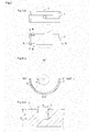
Fig. 2] Fig. 2(a) is a plan view of a halved member of the slide bearing according to the first embodiment,Fig. 2(b) is a A - A line sectional view; andFig. 2(c) is a B - B line sectional view. - [
Fig. 3] Fig. 3 is a graph which shows the relation between bearing angle and oil film thickness (as calculated value). - [
Fig. 4] Fig. 4 is graph which shows the relation between bearing angle and oil film pressure at the center part in the axial direction and the relation between bearing angle and oil film pressure gradient (as calculated value). - [
Fig. 5] Fig. 5 is a graph which shows the relation between bearing angle and rate of minimum oil film thickness. - [
Fig. 6] Fig. 6(a) is three-dimensional graph which shows gradient of oil film pressure of the slide bearing with narrow groove, andFig. 6(b) is three-dimensional graph which shows gradient of oil film pressure of the slide bearing without narrow groove(as calculated value). - [
Fig. 7] Fig. 7(a) is a graph which shows the relation between engine speed and change amount of the Friction Mean Effective Pressure (FMEP) concerning the bearing with grooves andFig. 7(b) is a graph which shows the relation between engine speed and change volume of the oil per minute concerning the bearing with grooves(as experimental value). - An embodiment of the invention is explained.
Fig. 1 is the front view of the slide bearing and the up and down direction on the drawing is defined as the up and down direction and the near and far direction on the drawing is defined as the axial direction (the front and back direction). - Firstly, the halved
members 2 which configure the slide bearing 1 concerning the first embodiment are explained with theFig.1 and theFig. 2 . - The slide bearing 1 is cylindrical member and it is adopted to the slide bearing structure of the
crankshaft 11 of the engine as shown inFig. 1 . The slide bearing 1 is configured by the two halvedmembers halved members halved members crankshaft 11 is held by the slide bearing 1, the clearance gap is configured and lubricating oil is supplied from oil route which is not shown toward the clearance gap. - In the
Fig. 2(a) , upper and lower halvedmembers 2 are shown. In the embodiment, the rotation direction of thecrankshaft 11 is clockwise direction on the front view as the vector shown in theFig 1 . In the bearing angle ω, the right edge in theFig 2(b) is defined as 0 degree and the counter clockwise direction shown inFig 2(b) is positive direction. Thus, in theFig 2(b) , the bearing angle ω at the left edge is defined as 180 degrees and the bearing angle ω at the down edge is defined as 270 degrees. - A groove is provided in the circumferential direction at the inner circumference of the upper halved
member 2 and the circle hole is provided at the center. The mating surfaces are disposed at the right and left side of the upper halvedmember 2 - In the slide surface of the inner circumference of the lower halved
member 2,narrow grooves 3 are configured at the edge in the axial direction. - The
narrow grooves 3 are provided at the lower halvedmember 2. In the embodiment, thenarrow grooves 3 are provided as two lines parallel to the axial direction. In detail,narrow grooves 3 are provided from the mating surface on the downstream side of the rotation direction of the crankshaft 11 (the bearing angle ω is 180 degrees) toward the direction in which the bearing angle ω is positive number(the counter clockwise direction). Thus, in the lower halvedmember 2, the mating surface on the right side in theFig. 2(b) is the mating surface on the downstream side of the rotation direction and the mating surface on the left side in theFig. 2(b) is the mating surface on the upstream side in the rotation direction. - As shown in the
Fig. 2(c) , thenarrow groove 3 is configured as the depth d is shallower than the bearing thickness D. The width of thenarrow groove 3 is configured as w. - Next, the
length 1 of thenarrow groove 3 is explained with theFig. 3 - At first, the case is explained that the
length 1 of thenarrow groove 3 is the length L1 from the mating surface on the downstream side of the rotation direction to the place of the minimum oil film thickness hmin. - The
Fig. 3 is a graph which shows the relation between a bearing angle ω and the oil film thickness h. The oil film thickness h is calculated based on the relation between the engine speed, the radius of the bearing, the width of the bearing, the viscosity of the oil, and crankshaft angle and the bearing load. The oil film thickness h decreases to minimum oil film thickness hmin with increasing the bearing angle ω from the mating surface on the downstream side of the rotation direction and increases with increasing the bearing angle ω. - Thus, the length L1 of the
narrow groove 3 is configured from the mating surface on the downstream side of the rotation direction (bearing angle ω is 180 degrees) to thehearing angle ω 1 where the oil film thickness becomes the minimum oil film thickness hmin. Furthermore, bearingangle ω 1 is the range of 180 degrees to 270 degrees. More detailed, bearing angle ω1 is the range of 225 degrees to 270 degrees. - Next, the case is explained that the length I of the
narrow groove 3 is the length L2 from the mating surface on the downstream side of the rotation direction to the place where the oil film pressure gradient is the maximum oil film pressure gradient ΔPMax1. - The
Fig. 4 is a graph which shows the relation between the bearing angle ω and the oil film pressure P and the relation between the bearing angle ω and the oil film pressure gradient Δ P. The oil film pressure P in theFig. 4 is calculated based on the relation between the engine speed, the radius of the bearing, the width of the bearing, the viscosity of the oil, and the crankshaft angle and the bearing load. The oil film pressure P increase to the maximum value PMax as drawing the curve upward with increasing the bearing angle ω from the mating surface on the downstream side of the rotation direction and decreases with increasing the bearing angle ω. - The oil film pressure gradient ΔP indicates the gradient of the inclination of the tangent at the point of the oil film pressure P and as shown in the
Fig. 4 the oil film pressure gradient ΔP increases to the local maximum value ΔPMax1 with increasing the bearing angle ω and decreases to the local minimum value ΔPmin1 with further increasing the bearing angle ω. The oil film pressure gradient ΔP increases to the local maximum value ΔPMax2 with further increasing the bearing angle ω and decreases to the local minimum value ΔPmin2 with further increasing the bearing angle ω. The oil film pressure gradient ΔP increases with further increasing the bearing angle ω. The local maximum value ΔPMax1 is bigger than local maximum value ΔPMax2. - Thus, the length L2 of the
narrow groove 3 is configured from the mating surface on the downstream side of the rotation direction (bearing angle ω is 180 degrees) to the bearing angle ω2 where the oil film pressure gradient is the maximum oil film pressure gradient ΔPMax1. Furthermore, the bearing angle ω2 is the range of 180 degrees to 270 degrees. More detailed, bearing angle ω2 is the range of 225 degrees to 270 degrees. - Next, the case is explained that the length I of the
narrow groove 3 is the length L3 in which the percentage of the minimum oil film thickness of the slide bearing I with processing thenarrow groove 3 to the bearing angle ω3 to the minimum oil film thickness (100%) of the slide bearing without a groove is 80%. The minimum oil film thickness of theslide bearing 1 in which the percentage of the minimum oil film thickness is 80% is the oil film thickness which is at least necessary for safe lubrication of theslide bearing 1. - The
Fig. 5 is a graph which shows the relation between the bearing angle ω and the percentage of the minimum oil film thickness. The percentage of the minimum oil film thickness is the percentage of the minimum oil film thickness of theslide bearing 1 processing thenarrow groove 3 to the bearing angle to the minimum oil film thickness (100%) of the slide bearing without a groove. The percentage of the minimum oil film thickness in theFig. 5 is calculated based on the relation between the engine speed, the radius of the bearing, the width of the bearing, the viscosity of the oil, and the crankshaft angle and the bearing load. The percentage of the minimum oil film thickness decreases with increasing thelength 1 of thenarrow groove 3. Therefore, the percentage of the minimum oil film thickness of theslide bearing 1 with processing thenarrow groove 3 to the bearing angle ω to the minimum oil film thickness of the slide bearing without a groove is smaller than 100%. - Thus, the length L3 of the
narrow groove 3 is configured as the length L3 from the mating surface on the downstream side of the rotation direction (bearing angle ω is 180 degrees) to bearingangle ω 3 in which the percentage of the minimum oil film thickness is 80%. Thebearing angle ω 3 is the range of 180 degrees to 270 degrees. More detailed, bearingangle ω 3 is the range of 225 degrees to 270 degrees. - As shown in the
Fig. 6(a) , by providing thenarrow groove 3 at the edge in the axial direction, the pressure gradient at the edge in the axial direction is able to be changed. Therefore, compared to without thenarrow groove 3 shown in theFig. 6(b) , at thenarrow groove 3 with increasing the pressure gradient which descends from the edge of the bearing to the center of the bearing, the suck back volume of the oil increases and the total volume of effluent oil can be reduced. - The
Fig. 7(a) is a graph which shows the relation between an engine speed and the change amount of the Friction Mean Effective Pressure (FMEP) in the each temperature. A circle (○) shows the change amount of the Friction Mean Effective Pressure (FMEP) in the temperature T1 and a square (□) shows the change amount of the Friction Mean Effective Pressure (FMEP) in the temperature T2. T1 is bigger than T2. By providing thenarrow groove 3, as shown theFig. 7(a) , regardless of the temperature of the oil the Friction Mean Effective Pressure can reduce. The FMEP is the value to see the tendency of the friction and the reduction of the FMEP means the reduction of the friction. - The
Fig. 7(b) is a graph which shows the relation between an engine speed and the change volume of oil per minutes in the each temperature. A circle (○) shows the change volume of the effluent oil per minutes in the temperature T1 and a square (□) shows the change volume of the effluent oil per minutes in the temperature T2. By providing thenarrow groove 3, as shown theFig. 7(b) , in the low temperature area of the oil in which T1 and T2 are contained, there is few change of the volume of the effluent oil per minutes and the increase of the total effluent oil can inhibit. - As stated above, the
slide bearing 1 in which halvedmembers narrow grooves 3 are provided at the end of the slide bearing in the circumferential direction from the mating surface on the downstream side of the rotation direction to the bearing angle ω and the bearing angle ω is the angle which is rotated in the range of ≥0 degree to ≤90 degrees from the mating surface on the downstream side of the rotation direction (bearing angle ω is 180 degrees) and in other words the bearing angle ω is the range of 180 degrees to 270 degrees. - By the structure, the narrow grooves which do not prevent the generation of the oil film pressure, the friction-reducing effect can be obtained with reducing the frictional area and the total volume of effluent oil can be reduced.
- The length l of the
narrow grooves 3 is the length L1 from the mating surface on the downstream side of the rotation direction to the bearing angle ω1 of the upstream side where the oil film thickness becomes the minimum oil film thickness hmin. - By the structure, the narrow grooves which do not prevent the generation of the oil film pressure, the friction-reducing effect can be obtained with reducing the frictional area and the total volume of effluent oil can be reduced.
- The length l of the
narrow grooves 3 is the length L2 from the mating surface on the downstream side of the rotation direction to the bearing angle ω2 of the upstream side where the oil film pressure gradient becomes the maximum oil film pressure gradient. - By the structure, the narrow grooves which don't prevent the generation of the oil film pressure, the friction-reducing effect can be obtained with reducing the frictional area and the total volume of effluent oil can be reduced.
- The length l of the
narrow grooves 3 is the length L3 by which the percentage of the minimum oil film thickness (100%) of theslide bearing 1 in which thenarrow grooves 3 are processed to the specified bearing angle ω3 to the minimum oil film thickness of a slide bearing without grooves is more than 80%. - By the structure, the narrow grooves which do not prevent the generation of the oil film pressure, the friction-reducing effect can be gotten with reducing the frictional area and the total volume of effluent oil can be reduced.
- The present invention is acceptable to the skill of the slide bearing and acceptable to the slide bearing in which halved members made by dividing a cylinder in two in a direction parallel to the axial are disposed vertically.
-
- 1
- slide bearing
- 2
- halved member
- 3
- narrow groove
- 11
- crankshaft
Claims (4)
- A slide bearing in which halved members made by dividing a cylinder in two in a direction parallel to the axial are disposed vertically,
wherein narrow grooves are provided at an end of the lower halved member in a circumferential direction from a mating surface on a downstream side of a rotation direction to a specified bearing angle,2
and wherein the specified bearing angle is an angle which is rotated in the range of ≥0 degree to ≤90 degrees from the mating surface on the downstream side of the rotation direction. - The slide bearing according to claim 1 wherein a length of the narrow groove is from the mating surface on the downstream side of the rotation direction to a place of an upstream side where oil film thickness becomes minimum.
- The slide bearing according to claim 1 wherein a length of the narrow groove is from the mating surface on the downstream side of the rotation direction to a place of an upstream side where oil film pressure gradient becomes maximum.
- The slide bearing according to claim 1 wherein a length of the narrow groove is the length by which a percentage of minimum oil film thickness of the slide bearing in which the narrow grooves are processed to the specified bearing angle to a minimum oil film thickness of a slide bearing without grooves is more than 80%.
Applications Claiming Priority (2)
| Application Number | Priority Date | Filing Date | Title |
|---|---|---|---|
| JP2013033837A JP5914383B2 (en) | 2013-02-22 | 2013-02-22 | Plain bearing |
| PCT/JP2014/054206 WO2014129595A1 (en) | 2013-02-22 | 2014-02-21 | Slide bearing |
Publications (3)
| Publication Number | Publication Date |
|---|---|
| EP2960533A1 true EP2960533A1 (en) | 2015-12-30 |
| EP2960533A4 EP2960533A4 (en) | 2016-05-11 |
| EP2960533B1 EP2960533B1 (en) | 2020-03-18 |
Family
ID=51391375
Family Applications (1)
| Application Number | Title | Priority Date | Filing Date |
|---|---|---|---|
| EP14754900.0A Active EP2960533B1 (en) | 2013-02-22 | 2014-02-21 | Slide bearing |
Country Status (5)
| Country | Link |
|---|---|
| US (1) | US9470266B2 (en) |
| EP (1) | EP2960533B1 (en) |
| JP (1) | JP5914383B2 (en) |
| CN (1) | CN105008733B (en) |
| WO (1) | WO2014129595A1 (en) |
Families Citing this family (4)
| Publication number | Priority date | Publication date | Assignee | Title |
|---|---|---|---|---|
| JP6724280B2 (en) * | 2015-12-17 | 2020-07-15 | 大豊工業株式会社 | Plain bearing |
| JP6624559B2 (en) * | 2015-12-17 | 2019-12-25 | 大豊工業株式会社 | Plain bearing |
| JP2017207108A (en) * | 2016-05-17 | 2017-11-24 | トヨタ自動車株式会社 | Bearing member |
| JP6876766B2 (en) * | 2019-09-30 | 2021-05-26 | 大同メタル工業株式会社 | Half bearings and plain bearings |
Family Cites Families (15)
| Publication number | Priority date | Publication date | Assignee | Title |
|---|---|---|---|---|
| US3680932A (en) * | 1970-09-10 | 1972-08-01 | Westinghouse Electric Corp | Stable journal bearing |
| JP2821769B2 (en) * | 1989-07-12 | 1998-11-05 | エヌデーシー株式会社 | Plain bearing |
| JPH06346913A (en) * | 1993-06-04 | 1994-12-20 | Nissan Motor Co Ltd | Engine crank lubricator |
| JPH08121459A (en) * | 1994-10-27 | 1996-05-14 | Yanmar Diesel Engine Co Ltd | Bearing structure for diesel engine |
| JPH10231841A (en) * | 1997-02-21 | 1998-09-02 | Daido Metal Co Ltd | Sliding bearing |
| JP2001032837A (en) * | 1999-07-21 | 2001-02-06 | Daido Metal Co Ltd | Slide bearing |
| GB0010542D0 (en) | 2000-05-03 | 2000-06-21 | Dana Corp | Bearings |
| JP3623737B2 (en) * | 2000-12-25 | 2005-02-23 | 大同メタル工業株式会社 | Half bearing |
| JP4507642B2 (en) | 2004-03-05 | 2010-07-21 | 日産自動車株式会社 | Low friction sliding shaft, crankshaft, camshaft, and engine |
| US7270482B2 (en) | 2004-02-05 | 2007-09-18 | Nissan Motor Co., Ltd. | Sliding device |
| JP5163873B2 (en) | 2008-02-18 | 2013-03-13 | 日産自動車株式会社 | Rotating shaft, sliding device using the same, rotating shaft machining device, rotating shaft machining method, crankshaft, camshaft, and engine |
| JP5340697B2 (en) | 2008-11-12 | 2013-11-13 | 大同メタル工業株式会社 | Sliding bearing for internal combustion engine and sliding bearing device |
| JP2011089563A (en) * | 2009-10-21 | 2011-05-06 | Toyota Motor Corp | Slide bearing |
| US9255606B2 (en) * | 2009-12-10 | 2016-02-09 | Hitachi, Ltd. | Slide bearing device and compressor |
| JP5524249B2 (en) * | 2012-01-17 | 2014-06-18 | 大同メタル工業株式会社 | Main bearing for crankshaft of internal combustion engine |
-
2013
- 2013-02-22 JP JP2013033837A patent/JP5914383B2/en active Active
-
2014
- 2014-02-21 CN CN201480009916.1A patent/CN105008733B/en not_active Expired - Fee Related
- 2014-02-21 WO PCT/JP2014/054206 patent/WO2014129595A1/en not_active Ceased
- 2014-02-21 US US14/769,604 patent/US9470266B2/en not_active Expired - Fee Related
- 2014-02-21 EP EP14754900.0A patent/EP2960533B1/en active Active
Also Published As
| Publication number | Publication date |
|---|---|
| EP2960533A4 (en) | 2016-05-11 |
| EP2960533B1 (en) | 2020-03-18 |
| US9470266B2 (en) | 2016-10-18 |
| WO2014129595A1 (en) | 2014-08-28 |
| US20150377285A1 (en) | 2015-12-31 |
| JP5914383B2 (en) | 2016-05-11 |
| CN105008733B (en) | 2017-04-19 |
| JP2014163432A (en) | 2014-09-08 |
| CN105008733A (en) | 2015-10-28 |
Similar Documents
| Publication | Publication Date | Title |
|---|---|---|
| US9879725B2 (en) | Sliding bearing | |
| US9657769B2 (en) | Slide bearing | |
| US9958007B2 (en) | Slide bearing | |
| EP2960533A1 (en) | Slide bearing | |
| EP3070354B1 (en) | Sliding bearing | |
| US8511900B2 (en) | Sliding bearing shell | |
| US9964139B2 (en) | Sliding bearing | |
| JP6166064B2 (en) | Plain bearing | |
| JP6624559B2 (en) | Plain bearing | |
| JP6541144B2 (en) | Slide bearing | |
| JP6399576B2 (en) | Plain bearing | |
| JP6724280B2 (en) | Plain bearing |
Legal Events
| Date | Code | Title | Description |
|---|---|---|---|
| PUAI | Public reference made under article 153(3) epc to a published international application that has entered the european phase |
Free format text: ORIGINAL CODE: 0009012 |
|
| 17P | Request for examination filed |
Effective date: 20150903 |
|
| AK | Designated contracting states |
Kind code of ref document: A1 Designated state(s): AL AT BE BG CH CY CZ DE DK EE ES FI FR GB GR HR HU IE IS IT LI LT LU LV MC MK MT NL NO PL PT RO RS SE SI SK SM TR |
|
| AX | Request for extension of the european patent |
Extension state: BA ME |
|
| A4 | Supplementary search report drawn up and despatched |
Effective date: 20160411 |
|
| RIC1 | Information provided on ipc code assigned before grant |
Ipc: F16C 33/10 20060101ALI20160405BHEP Ipc: F16C 17/02 20060101AFI20160405BHEP Ipc: F16C 33/14 20060101ALI20160405BHEP Ipc: F16C 9/02 20060101ALI20160405BHEP |
|
| DAX | Request for extension of the european patent (deleted) | ||
| STAA | Information on the status of an ep patent application or granted ep patent |
Free format text: STATUS: EXAMINATION IS IN PROGRESS |
|
| 17Q | First examination report despatched |
Effective date: 20181012 |
|
| GRAP | Despatch of communication of intention to grant a patent |
Free format text: ORIGINAL CODE: EPIDOSNIGR1 |
|
| STAA | Information on the status of an ep patent application or granted ep patent |
Free format text: STATUS: GRANT OF PATENT IS INTENDED |
|
| INTG | Intention to grant announced |
Effective date: 20190925 |
|
| RIN1 | Information on inventor provided before grant (corrected) |
Inventor name: KAJIKI, YUICHIRO Inventor name: ASHIHARA, KATSUHIRO Inventor name: HONDA, AKIHIRO Inventor name: TAKATA, HIROKI Inventor name: MURAKAMI, MOTOICHI |
|
| GRAS | Grant fee paid |
Free format text: ORIGINAL CODE: EPIDOSNIGR3 |
|
| GRAA | (expected) grant |
Free format text: ORIGINAL CODE: 0009210 |
|
| STAA | Information on the status of an ep patent application or granted ep patent |
Free format text: STATUS: THE PATENT HAS BEEN GRANTED |
|
| RAP1 | Party data changed (applicant data changed or rights of an application transferred) |
Owner name: TAIHO KOGYO CO., LTD Owner name: TOYOTA JIDOSHA KABUSHIKI KAISHA |
|
| RIN1 | Information on inventor provided before grant (corrected) |
Inventor name: KAJIKI, YUICHIRO Inventor name: TAKATA, HIROKI Inventor name: ASHIHARA, KATSUHIRO Inventor name: MURAKAMI, MOTOICHI Inventor name: HONDA, AKIHIRO |
|
| AK | Designated contracting states |
Kind code of ref document: B1 Designated state(s): AL AT BE BG CH CY CZ DE DK EE ES FI FR GB GR HR HU IE IS IT LI LT LU LV MC MK MT NL NO PL PT RO RS SE SI SK SM TR |
|
| REG | Reference to a national code |
Ref country code: GB Ref legal event code: FG4D |
|
| REG | Reference to a national code |
Ref country code: DE Ref legal event code: R096 Ref document number: 602014062525 Country of ref document: DE |
|
| REG | Reference to a national code |
Ref country code: AT Ref legal event code: REF Ref document number: 1246217 Country of ref document: AT Kind code of ref document: T Effective date: 20200415 Ref country code: IE Ref legal event code: FG4D |
|
| PG25 | Lapsed in a contracting state [announced via postgrant information from national office to epo] |
Ref country code: RS Free format text: LAPSE BECAUSE OF FAILURE TO SUBMIT A TRANSLATION OF THE DESCRIPTION OR TO PAY THE FEE WITHIN THE PRESCRIBED TIME-LIMIT Effective date: 20200318 Ref country code: NO Free format text: LAPSE BECAUSE OF FAILURE TO SUBMIT A TRANSLATION OF THE DESCRIPTION OR TO PAY THE FEE WITHIN THE PRESCRIBED TIME-LIMIT Effective date: 20200618 Ref country code: FI Free format text: LAPSE BECAUSE OF FAILURE TO SUBMIT A TRANSLATION OF THE DESCRIPTION OR TO PAY THE FEE WITHIN THE PRESCRIBED TIME-LIMIT Effective date: 20200318 |
|
| REG | Reference to a national code |
Ref country code: NL Ref legal event code: MP Effective date: 20200318 |
|
| PG25 | Lapsed in a contracting state [announced via postgrant information from national office to epo] |
Ref country code: SE Free format text: LAPSE BECAUSE OF FAILURE TO SUBMIT A TRANSLATION OF THE DESCRIPTION OR TO PAY THE FEE WITHIN THE PRESCRIBED TIME-LIMIT Effective date: 20200318 Ref country code: LV Free format text: LAPSE BECAUSE OF FAILURE TO SUBMIT A TRANSLATION OF THE DESCRIPTION OR TO PAY THE FEE WITHIN THE PRESCRIBED TIME-LIMIT Effective date: 20200318 Ref country code: HR Free format text: LAPSE BECAUSE OF FAILURE TO SUBMIT A TRANSLATION OF THE DESCRIPTION OR TO PAY THE FEE WITHIN THE PRESCRIBED TIME-LIMIT Effective date: 20200318 Ref country code: GR Free format text: LAPSE BECAUSE OF FAILURE TO SUBMIT A TRANSLATION OF THE DESCRIPTION OR TO PAY THE FEE WITHIN THE PRESCRIBED TIME-LIMIT Effective date: 20200619 Ref country code: BG Free format text: LAPSE BECAUSE OF FAILURE TO SUBMIT A TRANSLATION OF THE DESCRIPTION OR TO PAY THE FEE WITHIN THE PRESCRIBED TIME-LIMIT Effective date: 20200618 |
|
| REG | Reference to a national code |
Ref country code: LT Ref legal event code: MG4D |
|
| PG25 | Lapsed in a contracting state [announced via postgrant information from national office to epo] |
Ref country code: NL Free format text: LAPSE BECAUSE OF FAILURE TO SUBMIT A TRANSLATION OF THE DESCRIPTION OR TO PAY THE FEE WITHIN THE PRESCRIBED TIME-LIMIT Effective date: 20200318 |
|
| PG25 | Lapsed in a contracting state [announced via postgrant information from national office to epo] |
Ref country code: EE Free format text: LAPSE BECAUSE OF FAILURE TO SUBMIT A TRANSLATION OF THE DESCRIPTION OR TO PAY THE FEE WITHIN THE PRESCRIBED TIME-LIMIT Effective date: 20200318 Ref country code: SM Free format text: LAPSE BECAUSE OF FAILURE TO SUBMIT A TRANSLATION OF THE DESCRIPTION OR TO PAY THE FEE WITHIN THE PRESCRIBED TIME-LIMIT Effective date: 20200318 Ref country code: CZ Free format text: LAPSE BECAUSE OF FAILURE TO SUBMIT A TRANSLATION OF THE DESCRIPTION OR TO PAY THE FEE WITHIN THE PRESCRIBED TIME-LIMIT Effective date: 20200318 Ref country code: PT Free format text: LAPSE BECAUSE OF FAILURE TO SUBMIT A TRANSLATION OF THE DESCRIPTION OR TO PAY THE FEE WITHIN THE PRESCRIBED TIME-LIMIT Effective date: 20200812 Ref country code: RO Free format text: LAPSE BECAUSE OF FAILURE TO SUBMIT A TRANSLATION OF THE DESCRIPTION OR TO PAY THE FEE WITHIN THE PRESCRIBED TIME-LIMIT Effective date: 20200318 Ref country code: LT Free format text: LAPSE BECAUSE OF FAILURE TO SUBMIT A TRANSLATION OF THE DESCRIPTION OR TO PAY THE FEE WITHIN THE PRESCRIBED TIME-LIMIT Effective date: 20200318 Ref country code: SK Free format text: LAPSE BECAUSE OF FAILURE TO SUBMIT A TRANSLATION OF THE DESCRIPTION OR TO PAY THE FEE WITHIN THE PRESCRIBED TIME-LIMIT Effective date: 20200318 Ref country code: IS Free format text: LAPSE BECAUSE OF FAILURE TO SUBMIT A TRANSLATION OF THE DESCRIPTION OR TO PAY THE FEE WITHIN THE PRESCRIBED TIME-LIMIT Effective date: 20200718 |
|
| REG | Reference to a national code |
Ref country code: AT Ref legal event code: MK05 Ref document number: 1246217 Country of ref document: AT Kind code of ref document: T Effective date: 20200318 |
|
| REG | Reference to a national code |
Ref country code: DE Ref legal event code: R097 Ref document number: 602014062525 Country of ref document: DE |
|
| PLBE | No opposition filed within time limit |
Free format text: ORIGINAL CODE: 0009261 |
|
| STAA | Information on the status of an ep patent application or granted ep patent |
Free format text: STATUS: NO OPPOSITION FILED WITHIN TIME LIMIT |
|
| PG25 | Lapsed in a contracting state [announced via postgrant information from national office to epo] |
Ref country code: IT Free format text: LAPSE BECAUSE OF FAILURE TO SUBMIT A TRANSLATION OF THE DESCRIPTION OR TO PAY THE FEE WITHIN THE PRESCRIBED TIME-LIMIT Effective date: 20200318 Ref country code: AT Free format text: LAPSE BECAUSE OF FAILURE TO SUBMIT A TRANSLATION OF THE DESCRIPTION OR TO PAY THE FEE WITHIN THE PRESCRIBED TIME-LIMIT Effective date: 20200318 Ref country code: DK Free format text: LAPSE BECAUSE OF FAILURE TO SUBMIT A TRANSLATION OF THE DESCRIPTION OR TO PAY THE FEE WITHIN THE PRESCRIBED TIME-LIMIT Effective date: 20200318 Ref country code: ES Free format text: LAPSE BECAUSE OF FAILURE TO SUBMIT A TRANSLATION OF THE DESCRIPTION OR TO PAY THE FEE WITHIN THE PRESCRIBED TIME-LIMIT Effective date: 20200318 |
|
| 26N | No opposition filed |
Effective date: 20201221 |
|
| PG25 | Lapsed in a contracting state [announced via postgrant information from national office to epo] |
Ref country code: PL Free format text: LAPSE BECAUSE OF FAILURE TO SUBMIT A TRANSLATION OF THE DESCRIPTION OR TO PAY THE FEE WITHIN THE PRESCRIBED TIME-LIMIT Effective date: 20200318 |
|
| PG25 | Lapsed in a contracting state [announced via postgrant information from national office to epo] |
Ref country code: SI Free format text: LAPSE BECAUSE OF FAILURE TO SUBMIT A TRANSLATION OF THE DESCRIPTION OR TO PAY THE FEE WITHIN THE PRESCRIBED TIME-LIMIT Effective date: 20200318 |
|
| PG25 | Lapsed in a contracting state [announced via postgrant information from national office to epo] |
Ref country code: MC Free format text: LAPSE BECAUSE OF FAILURE TO SUBMIT A TRANSLATION OF THE DESCRIPTION OR TO PAY THE FEE WITHIN THE PRESCRIBED TIME-LIMIT Effective date: 20200318 |
|
| GBPC | Gb: european patent ceased through non-payment of renewal fee |
Effective date: 20210221 |
|
| REG | Reference to a national code |
Ref country code: BE Ref legal event code: MM Effective date: 20210228 |
|
| PG25 | Lapsed in a contracting state [announced via postgrant information from national office to epo] |
Ref country code: CH Free format text: LAPSE BECAUSE OF NON-PAYMENT OF DUE FEES Effective date: 20210228 Ref country code: LI Free format text: LAPSE BECAUSE OF NON-PAYMENT OF DUE FEES Effective date: 20210228 Ref country code: LU Free format text: LAPSE BECAUSE OF NON-PAYMENT OF DUE FEES Effective date: 20210221 |
|
| PG25 | Lapsed in a contracting state [announced via postgrant information from national office to epo] |
Ref country code: GB Free format text: LAPSE BECAUSE OF NON-PAYMENT OF DUE FEES Effective date: 20210221 Ref country code: FR Free format text: LAPSE BECAUSE OF NON-PAYMENT OF DUE FEES Effective date: 20210228 Ref country code: IE Free format text: LAPSE BECAUSE OF NON-PAYMENT OF DUE FEES Effective date: 20210221 |
|
| PG25 | Lapsed in a contracting state [announced via postgrant information from national office to epo] |
Ref country code: BE Free format text: LAPSE BECAUSE OF NON-PAYMENT OF DUE FEES Effective date: 20210228 |
|
| PG25 | Lapsed in a contracting state [announced via postgrant information from national office to epo] |
Ref country code: HU Free format text: LAPSE BECAUSE OF FAILURE TO SUBMIT A TRANSLATION OF THE DESCRIPTION OR TO PAY THE FEE WITHIN THE PRESCRIBED TIME-LIMIT; INVALID AB INITIO Effective date: 20140221 |
|
| PGFP | Annual fee paid to national office [announced via postgrant information from national office to epo] |
Ref country code: DE Payment date: 20221229 Year of fee payment: 10 |
|
| PG25 | Lapsed in a contracting state [announced via postgrant information from national office to epo] |
Ref country code: CY Free format text: LAPSE BECAUSE OF FAILURE TO SUBMIT A TRANSLATION OF THE DESCRIPTION OR TO PAY THE FEE WITHIN THE PRESCRIBED TIME-LIMIT Effective date: 20200318 |
|
| PG25 | Lapsed in a contracting state [announced via postgrant information from national office to epo] |
Ref country code: MK Free format text: LAPSE BECAUSE OF FAILURE TO SUBMIT A TRANSLATION OF THE DESCRIPTION OR TO PAY THE FEE WITHIN THE PRESCRIBED TIME-LIMIT Effective date: 20200318 |
|
| REG | Reference to a national code |
Ref country code: DE Ref legal event code: R119 Ref document number: 602014062525 Country of ref document: DE |
|
| PG25 | Lapsed in a contracting state [announced via postgrant information from national office to epo] |
Ref country code: MT Free format text: LAPSE BECAUSE OF FAILURE TO SUBMIT A TRANSLATION OF THE DESCRIPTION OR TO PAY THE FEE WITHIN THE PRESCRIBED TIME-LIMIT Effective date: 20200318 |
|
| PG25 | Lapsed in a contracting state [announced via postgrant information from national office to epo] |
Ref country code: DE Free format text: LAPSE BECAUSE OF NON-PAYMENT OF DUE FEES Effective date: 20240903 |
|
| PG25 | Lapsed in a contracting state [announced via postgrant information from national office to epo] |
Ref country code: DE Free format text: LAPSE BECAUSE OF NON-PAYMENT OF DUE FEES Effective date: 20240903 |
|
| PG25 | Lapsed in a contracting state [announced via postgrant information from national office to epo] |
Ref country code: TR Free format text: LAPSE BECAUSE OF FAILURE TO SUBMIT A TRANSLATION OF THE DESCRIPTION OR TO PAY THE FEE WITHIN THE PRESCRIBED TIME-LIMIT Effective date: 20200318 |