EP2960529A1 - Hydraulic system for construction machine, provided with protection device - Google Patents
Hydraulic system for construction machine, provided with protection device Download PDFInfo
- Publication number
- EP2960529A1 EP2960529A1 EP13875723.2A EP13875723A EP2960529A1 EP 2960529 A1 EP2960529 A1 EP 2960529A1 EP 13875723 A EP13875723 A EP 13875723A EP 2960529 A1 EP2960529 A1 EP 2960529A1
- Authority
- EP
- European Patent Office
- Prior art keywords
- hydraulic
- hydraulic fluid
- fluid temperature
- hydraulic pump
- flow rate
- Prior art date
- Legal status (The legal status is an assumption and is not a legal conclusion. Google has not performed a legal analysis and makes no representation as to the accuracy of the status listed.)
- Granted
Links
Images


Classifications
-
- F—MECHANICAL ENGINEERING; LIGHTING; HEATING; WEAPONS; BLASTING
- F15—FLUID-PRESSURE ACTUATORS; HYDRAULICS OR PNEUMATICS IN GENERAL
- F15B—SYSTEMS ACTING BY MEANS OF FLUIDS IN GENERAL; FLUID-PRESSURE ACTUATORS, e.g. SERVOMOTORS; DETAILS OF FLUID-PRESSURE SYSTEMS, NOT OTHERWISE PROVIDED FOR
- F15B11/00—Servomotor systems without provision for follow-up action; Circuits therefor
- F15B11/02—Systems essentially incorporating special features for controlling the speed or actuating force of an output member
- F15B11/04—Systems essentially incorporating special features for controlling the speed or actuating force of an output member for controlling the speed
- F15B11/042—Systems essentially incorporating special features for controlling the speed or actuating force of an output member for controlling the speed by means in the feed line, i.e. "meter in"
- F15B11/0423—Systems essentially incorporating special features for controlling the speed or actuating force of an output member for controlling the speed by means in the feed line, i.e. "meter in" by controlling pump output or bypass, other than to maintain constant speed
-
- E—FIXED CONSTRUCTIONS
- E02—HYDRAULIC ENGINEERING; FOUNDATIONS; SOIL SHIFTING
- E02F—DREDGING; SOIL-SHIFTING
- E02F9/00—Component parts of dredgers or soil-shifting machines, not restricted to one of the kinds covered by groups E02F3/00 - E02F7/00
- E02F9/20—Drives; Control devices
- E02F9/22—Hydraulic or pneumatic drives
- E02F9/2221—Control of flow rate; Load sensing arrangements
- E02F9/2232—Control of flow rate; Load sensing arrangements using one or more variable displacement pumps
- E02F9/2235—Control of flow rate; Load sensing arrangements using one or more variable displacement pumps including an electronic controller
-
- E—FIXED CONSTRUCTIONS
- E02—HYDRAULIC ENGINEERING; FOUNDATIONS; SOIL SHIFTING
- E02F—DREDGING; SOIL-SHIFTING
- E02F9/00—Component parts of dredgers or soil-shifting machines, not restricted to one of the kinds covered by groups E02F3/00 - E02F7/00
- E02F9/20—Drives; Control devices
- E02F9/22—Hydraulic or pneumatic drives
- E02F9/226—Safety arrangements, e.g. hydraulic driven fans, preventing cavitation, leakage, overheating
-
- E—FIXED CONSTRUCTIONS
- E02—HYDRAULIC ENGINEERING; FOUNDATIONS; SOIL SHIFTING
- E02F—DREDGING; SOIL-SHIFTING
- E02F9/00—Component parts of dredgers or soil-shifting machines, not restricted to one of the kinds covered by groups E02F3/00 - E02F7/00
- E02F9/20—Drives; Control devices
- E02F9/22—Hydraulic or pneumatic drives
- E02F9/2278—Hydraulic circuits
- E02F9/2296—Systems with a variable displacement pump
-
- F—MECHANICAL ENGINEERING; LIGHTING; HEATING; WEAPONS; BLASTING
- F15—FLUID-PRESSURE ACTUATORS; HYDRAULICS OR PNEUMATICS IN GENERAL
- F15B—SYSTEMS ACTING BY MEANS OF FLUIDS IN GENERAL; FLUID-PRESSURE ACTUATORS, e.g. SERVOMOTORS; DETAILS OF FLUID-PRESSURE SYSTEMS, NOT OTHERWISE PROVIDED FOR
- F15B20/00—Safety arrangements for fluid actuator systems; Applications of safety devices in fluid actuator systems; Emergency measures for fluid actuator systems
-
- F—MECHANICAL ENGINEERING; LIGHTING; HEATING; WEAPONS; BLASTING
- F15—FLUID-PRESSURE ACTUATORS; HYDRAULICS OR PNEUMATICS IN GENERAL
- F15B—SYSTEMS ACTING BY MEANS OF FLUIDS IN GENERAL; FLUID-PRESSURE ACTUATORS, e.g. SERVOMOTORS; DETAILS OF FLUID-PRESSURE SYSTEMS, NOT OTHERWISE PROVIDED FOR
- F15B2211/00—Circuits for servomotor systems
- F15B2211/20—Fluid pressure source, e.g. accumulator or variable axial piston pump
- F15B2211/205—Systems with pumps
- F15B2211/2053—Type of pump
- F15B2211/20546—Type of pump variable capacity
-
- F—MECHANICAL ENGINEERING; LIGHTING; HEATING; WEAPONS; BLASTING
- F15—FLUID-PRESSURE ACTUATORS; HYDRAULICS OR PNEUMATICS IN GENERAL
- F15B—SYSTEMS ACTING BY MEANS OF FLUIDS IN GENERAL; FLUID-PRESSURE ACTUATORS, e.g. SERVOMOTORS; DETAILS OF FLUID-PRESSURE SYSTEMS, NOT OTHERWISE PROVIDED FOR
- F15B2211/00—Circuits for servomotor systems
- F15B2211/30—Directional control
- F15B2211/31—Directional control characterised by the positions of the valve element
- F15B2211/3105—Neutral or centre positions
- F15B2211/3116—Neutral or centre positions the pump port being open in the centre position, e.g. so-called open centre
-
- F—MECHANICAL ENGINEERING; LIGHTING; HEATING; WEAPONS; BLASTING
- F15—FLUID-PRESSURE ACTUATORS; HYDRAULICS OR PNEUMATICS IN GENERAL
- F15B—SYSTEMS ACTING BY MEANS OF FLUIDS IN GENERAL; FLUID-PRESSURE ACTUATORS, e.g. SERVOMOTORS; DETAILS OF FLUID-PRESSURE SYSTEMS, NOT OTHERWISE PROVIDED FOR
- F15B2211/00—Circuits for servomotor systems
- F15B2211/40—Flow control
-
- F—MECHANICAL ENGINEERING; LIGHTING; HEATING; WEAPONS; BLASTING
- F15—FLUID-PRESSURE ACTUATORS; HYDRAULICS OR PNEUMATICS IN GENERAL
- F15B—SYSTEMS ACTING BY MEANS OF FLUIDS IN GENERAL; FLUID-PRESSURE ACTUATORS, e.g. SERVOMOTORS; DETAILS OF FLUID-PRESSURE SYSTEMS, NOT OTHERWISE PROVIDED FOR
- F15B2211/00—Circuits for servomotor systems
- F15B2211/40—Flow control
- F15B2211/45—Control of bleed-off flow, e.g. control of bypass flow to the return line
-
- F—MECHANICAL ENGINEERING; LIGHTING; HEATING; WEAPONS; BLASTING
- F15—FLUID-PRESSURE ACTUATORS; HYDRAULICS OR PNEUMATICS IN GENERAL
- F15B—SYSTEMS ACTING BY MEANS OF FLUIDS IN GENERAL; FLUID-PRESSURE ACTUATORS, e.g. SERVOMOTORS; DETAILS OF FLUID-PRESSURE SYSTEMS, NOT OTHERWISE PROVIDED FOR
- F15B2211/00—Circuits for servomotor systems
- F15B2211/60—Circuit components or control therefor
- F15B2211/61—Secondary circuits
- F15B2211/611—Diverting circuits, e.g. for cooling or filtering
-
- F—MECHANICAL ENGINEERING; LIGHTING; HEATING; WEAPONS; BLASTING
- F15—FLUID-PRESSURE ACTUATORS; HYDRAULICS OR PNEUMATICS IN GENERAL
- F15B—SYSTEMS ACTING BY MEANS OF FLUIDS IN GENERAL; FLUID-PRESSURE ACTUATORS, e.g. SERVOMOTORS; DETAILS OF FLUID-PRESSURE SYSTEMS, NOT OTHERWISE PROVIDED FOR
- F15B2211/00—Circuits for servomotor systems
- F15B2211/60—Circuit components or control therefor
- F15B2211/62—Cooling or heating means
-
- F—MECHANICAL ENGINEERING; LIGHTING; HEATING; WEAPONS; BLASTING
- F15—FLUID-PRESSURE ACTUATORS; HYDRAULICS OR PNEUMATICS IN GENERAL
- F15B—SYSTEMS ACTING BY MEANS OF FLUIDS IN GENERAL; FLUID-PRESSURE ACTUATORS, e.g. SERVOMOTORS; DETAILS OF FLUID-PRESSURE SYSTEMS, NOT OTHERWISE PROVIDED FOR
- F15B2211/00—Circuits for servomotor systems
- F15B2211/60—Circuit components or control therefor
- F15B2211/63—Electronic controllers
- F15B2211/6303—Electronic controllers using input signals
- F15B2211/6343—Electronic controllers using input signals representing a temperature
-
- F—MECHANICAL ENGINEERING; LIGHTING; HEATING; WEAPONS; BLASTING
- F15—FLUID-PRESSURE ACTUATORS; HYDRAULICS OR PNEUMATICS IN GENERAL
- F15B—SYSTEMS ACTING BY MEANS OF FLUIDS IN GENERAL; FLUID-PRESSURE ACTUATORS, e.g. SERVOMOTORS; DETAILS OF FLUID-PRESSURE SYSTEMS, NOT OTHERWISE PROVIDED FOR
- F15B2211/00—Circuits for servomotor systems
- F15B2211/60—Circuit components or control therefor
- F15B2211/665—Methods of control using electronic components
- F15B2211/6652—Control of the pressure source, e.g. control of the swash plate angle
Definitions
- the present invention relates to a hydraulic system for a construction machine having a protection device, and more particularly to a hydraulic system for a construction machine having a protection device, which can limit a flow rate of hydraulic fluid that is discharged from a hydraulic pump in accordance with a hydraulic fluid temperature of the hydraulic fluid that operates a hydraulic actuator and notify an operator of information on the hydraulic fluid temperature.
- a hydraulic system for a construction machine in the related art includes a variable displacement hydraulic pump 2 (hereinafter referred to as "hydraulic pump") operated by an engine 1, a hydraulic actuator 3 (e.g., boom cylinder) operated by hydraulic fluid that is supplied from the hydraulic pump 2, a control valve (MCV) 4 installed in a flow path between the hydraulic pump 2 and the hydraulic actuator 3 to control a flow rate of the hydraulic fluid that is supplied from the hydraulic pump 2 to the hydraulic actuator 3 when a spool thereof is shifted, an oil cooler 7 installed in a return flow path 6 from the control valve 4 to a hydraulic fluid tank 5 to cool the hydraulic fluid that returns to the hydraulic fluid tank 5, a hydraulic pump regulator 8 controlling a discharge flow rate of the hydraulic pump 2 through adjustment of an inclination angle of a swash plate of the hydraulic pump 2, and a controller 9 outputting a control signal to the hydraulic pump regulator 8 or an engine revolution control device (not illustrated) of the engine 1 so as to limit the discharge flow rate of the hydraulic pump 2 to
- the hydraulic system for a construction machine in the related art as described above operates to lower the hydraulic fluid temperature through heightening of the rotating speed of a cooling fan if the hydraulic fluid temperature of the hydraulic fluid tank 15 exceeds a predetermined upper limit value and to make the hydraulic fluid temperature belong to a certain temperature range between a lower limit value and the upper limit value through lowering of the rotating speed of the cooling fan if the hydraulic fluid temperature is lower than the predetermined lower limit value.
- hydraulic components may be damaged, or a seal for preventing oil leak that is installed on the hydraulic actuator or hydraulic pipes may be damaged to cause oil leak.
- the present invention has been made to solve the aforementioned problems occurring in the related art, and it is an object of the present invention to provide a hydraulic system for a construction machine having a protection device, which can prevent a hydraulic system that includes a hydraulic pump from being damaged by limiting a flow rate of hydraulic fluid that is discharged from the hydraulic pump in accordance with a hydraulic fluid temperature of the hydraulic fluid, and can protect the hydraulic system by warning an operator so that the operator can take proper safety measures.
- a hydraulic system for a construction machine having a protection device which includes a variable displacement hydraulic pump; a hydraulic actuator operated by hydraulic fluid that is supplied from the hydraulic pump; a control valve installed in a flow path between the hydraulic pump and the hydraulic actuator to control a flow rate of the hydraulic fluid that is supplied from the hydraulic pump to the hydraulic actuator; an oil cooler installed in a return flow path from the control valve to a hydraulic fluid tank to cool the hydraulic fluid; a hydraulic fluid temperature sensor detecting in real time a hydraulic fluid temperature of the hydraulic fluid tank; a hydraulic pump regulator controlling a discharge flow rate of the hydraulic pump through adjustment of an inclination angle of a swash plate of the hydraulic pump; and a controller comparing the hydraulic fluid temperature detected by the hydraulic fluid temperature sensor with a predetermined hydraulic fluid temperature, and outputting a control signal to the hydraulic pump regulator so as to limit the discharge flow rate of the hydraulic pump to or below a predetermined flow rate if the detected hydraulic fluid temperature is equal to or
- a hydraulic system for a construction machine having a protection device which includes a variable displacement hydraulic pump operated by an engine; a hydraulic actuator operated by hydraulic fluid that is supplied from the hydraulic pump; a control valve installed in a flow path between the hydraulic pump and the hydraulic actuator to control a flow rate of the hydraulic fluid that is supplied from the hydraulic pump to the hydraulic actuator; an oil cooler installed in a return flow path from the control valve to a hydraulic fluid tank to cool the hydraulic fluid; a hydraulic fluid temperature sensor detecting in real time a hydraulic fluid temperature of the hydraulic fluid tank; a hydraulic pump regulator controlling a discharge flow rate of the hydraulic pump through adjustment of an inclination angle of a swash plate of the hydraulic pump; and a controller comparing the hydraulic fluid temperature detected by the hydraulic fluid temperature sensor with a predetermined hydraulic fluid temperature, and outputting a control signal to an engine revolution control device of the engine so as to limit the discharge flow rate of the hydraulic pump to or below a predetermined flow rate through adjustment of an engine revolution of the engine
- a hydraulic system for a construction machine having a protection device which includes a variable displacement hydraulic pump; a hydraulic actuator operated by hydraulic fluid that is supplied from the hydraulic pump; a control valve installed in a flow path between the hydraulic pump and the hydraulic actuator to control a flow rate of the hydraulic fluid that is supplied from the hydraulic pump to the hydraulic actuator; an oil cooler installed in a return flow path from the control valve to a hydraulic fluid tank to cool the hydraulic fluid; a hydraulic fluid temperature sensor detecting in real time a hydraulic fluid temperature of the hydraulic fluid tank; a hydraulic pump regulator controlling a discharge flow rate of the hydraulic pump through adjustment of an inclination angle of a swash plate of the hydraulic pump; a pressure detection sensor detecting pressure of the hydraulic pump; a flow rate detection sensor detecting the discharge flow rate of the hydraulic pump; and a controller comparing the hydraulic fluid temperature detected by the hydraulic fluid temperature sensor with a predetermined hydraulic fluid temperature, calculating a torque in accordance with the detected discharge flow rate and pressure of the hydraulic pump
- the controller may include a control means for controlling the discharge flow rate of the hydraulic pump in accordance with the hydraulic fluid temperature detected by the hydraulic fluid temperature sensor, checking the hydraulic fluid temperature in real time, and releasing the function of limiting the discharge flow rate of the hydraulic pump to or below the predetermined flow rate if the detected hydraulic fluid temperature belongs to a certain temperature range between the lower limit value and the upper limit value.
- the controller may include a warning means for notifying an operator on an operator's seat of information on the hydraulic fluid temperature if the detected hydraulic fluid temperature, which is input from the hydraulic fluid temperature sensor to the controller, is equal to or lower than the predetermined lower limit value, or equal to or higher than the predetermined upper limit value.
- Any one of an alarm, a buzzer, and a sound message may be used as the warning means.
- the hydraulic system that includes the hydraulic pump can be prevented from being damaged due to the cavitation that occurs when the hydraulic fluid temperature is lower than the lower limit value, and the oil leak can be prevented, which occurs due to the damage of the hydraulic components or the seal that occurs when the hydraulic fluid temperature is higher than the upper limit value. Further, since the operator is notified of the hydraulic fluid temperature information, the operator can take proper safety measures to protect the hydraulic system.
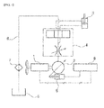
- Fig. 3 is a hydraulic circuit diagram of a hydraulic system for a construction machine having a protection device according to a first preferred embodiment of the present invention
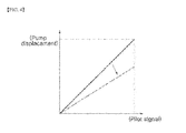
- Fig. 4 is a diagram explaining the displacement volume control characteristic of a hydraulic pump in a hydraulic system for a construction machine having a protection device according to a first preferred embodiment of the present invention
- Fig. 5 is a flowchart explaining displacement volume control of a hydraulic pump in a hydraulic system for a construction machine having a protection device according to a first preferred embodiment of the present invention
- Fig. 6 is a flowchart explaining engine revolution control in a hydraulic system for a construction machine having a protection device according to a second preferred embodiment of the present invention
- Fig. 7 is a flowchart explaining input torque control of a hydraulic pump in a hydraulic system for a construction machine having a protection device according to a second preferred embodiment of the present invention.
- a hydraulic system for a construction machine having a protection device includes a variable displacement hydraulic pump 2 (hereinafter referred to as "hydraulic pump") operated by an engine 1; a hydraulic actuator 3 (e.g., boom cylinder) operated by hydraulic fluid that is supplied from the hydraulic pump 2; a control valve (MCV) 14 installed in a flow path between the hydraulic pump 12 and the hydraulic actuator 13 to control a flow rate of the hydraulic fluid that is supplied from the hydraulic pump 12 to the hydraulic actuator 13; an oil cooler 17 installed in a return flow path 16 from the control valve 14 to a hydraulic fluid tank 15 to cool the hydraulic fluid that returns to the hydraulic fluid tank 15; a hydraulic fluid temperature sensor 20 detecting in real time a hydraulic fluid temperature of the hydraulic fluid tank 15; a hydraulic pump regulator 18 controlling a discharge flow rate of the hydraulic pump 12 through adjustment of an inclination angle of a swash plate of the hydraulic pump 12; and a controller 19 comparing the hydraulic fluid temperature that is detected
- the controller 19 may include a control means (not illustrated) for controlling the discharge flow rate of the hydraulic pump 12 in accordance with the hydraulic fluid temperature detected by the hydraulic fluid temperature sensor 20, checking the hydraulic fluid temperature in real time, and releasing the function of limiting the discharge flow rate of the hydraulic pump 12 to or below the predetermined flow rate if the detected hydraulic fluid temperature belongs to a certain temperature range between the lower limit value and the upper limit value.
- the controller 19 may include a warning means (not illustrated) for notifying an operator on an operator's seat of information on the hydraulic fluid temperature if the detected hydraulic fluid temperature, which is input from the hydraulic fluid temperature sensor (20) to the controller 19, is equal to or lower than the predetermined lower limit value, or equal to or higher than the predetermined upper limit value.
- Any one of an alarm, a buzzer, and a sound message may be used as the warning means.
- the hydraulic fluid temperature of the hydraulic fluid tank 15 is detected by the hydraulic fluid temperature sensor 20, and the detected hydraulic fluid temperature value is output to the controller 19 (S10).
- the hydraulic fluid temperature that is input to the controller 19 and the predetermined hydraulic fluid temperature are compared with each other. If the detected hydraulic fluid temperature is equal to or higher than the predetermined lower limit value, the processing proceeds to S30, whereas if the detected hydraulic fluid temperature is lower than the predetermined lower limit value, the processing proceeds to S50.
- the hydraulic fluid temperature that is input to the controller 19 and the predetermined hydraulic fluid temperature are compared with each other. If the hydraulic fluid temperature that is detected by the hydraulic fluid temperature sensor 20 is equal to or lower than the predetermined upper limit value, the processing proceeds to S40, whereas if the hydraulic fluid temperature that is detected by the hydraulic fluid temperature sensor 20 is higher than the predetermined upper limit value, the processing proceeds to S50.
- the controller 19 determines that the hydraulic fluid temperature of the hydraulic fluid is at a normal level. Accordingly, the hydraulic fluid of the hydraulic pump 12 is discharged with the predetermined flow rate corresponding to the control signal that is input from the controller 19 to the hydraulic pump regulator 18.
- the controller 19 determines that the hydraulic fluid temperature of the hydraulic fluid deviates from the normal level. Accordingly, if the hydraulic fluid temperature that is input to the controller 19 is equal to or lower than the predetermined lower limit value, the inclination angle of the swash plate of the hydraulic pump 12 is limited by the control signal that is input from the controller 19 to the hydraulic pump regulator 18 to limit the displacement volume thereof. Through this, the discharge flow rate of the hydraulic pump 12 is limited to or below the predetermined flow rate until the hydraulic fluid temperature that is detected in real time by the hydraulic fluid temperature sensor 20 to be input to the controller 19 exceeds the predetermined lower limit value.
- the inclination angle of the swash plate of the hydraulic pump 12 is limited by the control signal that is input from the controller 19 to the hydraulic pump regulator 18 to limit the displacement volume thereof (the displacement volume of the hydraulic pump 12 is reduced other than being in proportion to the applied pilot signal as shown in Fig. 4 ).
- the discharge flow rate of the hydraulic pump 12 is limited to or below the predetermined flow rate until the hydraulic fluid temperature that is detected in real time by the hydraulic fluid temperature sensor 20 to be input to the controller 19 becomes lower than the predetermined upper limit value.
- the discharge flow rate of the hydraulic pump 12 can be limited to the predetermined flow rate through limiting of the displacement volume of the hydraulic pump 12.
- an operator on an operator's seat is notified of information on the hydraulic fluid temperature. Through this, the operator determines that the hydraulic fluid temperature of the hydraulic fluid deviates from the normal level, and thus can take proper safety measures to protect the hydraulic system.
- a hydraulic system for a construction machine having a protection device includes a variable displacement hydraulic pump 2 (hereinafter referred to as "hydraulic pump") operated by an engine 1; a hydraulic actuator 3 (e.g., boom cylinder) operated by hydraulic fluid that is supplied from the hydraulic pump 2; a control valve (MCV) 14 installed in a flow path between the hydraulic pump 12 and the hydraulic actuator 13 to control a flow rate of the hydraulic fluid that is supplied from the hydraulic pump 12 to the hydraulic actuator 13; an oil cooler 17 installed in a return flow path 16 from the control valve 14 to a hydraulic fluid tank 15 to cool the hydraulic fluid that returns to the hydraulic fluid tank 15; a hydraulic fluid temperature sensor 20 detecting in real time a hydraulic fluid temperature of the hydraulic fluid tank 15; a hydraulic pump regulator 18 controlling a discharge flow rate of the hydraulic pump 12 through adjustment of an inclination angle of a swash plate of the hydraulic pump 12; and a controller 19 comparing the hydraulic fluid temperature that is detected
- the configuration except for the controller 19 outputting the control signal to the engine revolution control device of the engine 11 so as to limit the discharge flow rate of the hydraulic pump 12 to or below the predetermined flow rate through adjustment of the engine revolution of the engine 11 if the detected hydraulic fluid temperature is equal to or lower than the predetermined lower limit value, or equal to or higher than the predetermined upper limit value, is the same as the configuration of the hydraulic system for a construction machine having a protection device according to the first embodiment of the present invention, the detailed explanation thereof will be omitted.
- the hydraulic fluid temperature of the hydraulic fluid tank 15 is detected by the hydraulic fluid temperature sensor 20, and the detected hydraulic fluid temperature value is output to the controller 19 (S100).
- the hydraulic fluid temperature that is input to the controller 19 and the predetermined hydraulic fluid temperature are compared with each other. If the hydraulic fluid temperature that is detected by the hydraulic fluid temperature sensor 20 is equal to or higher than the predetermined lower limit value, the processing proceeds to S300, whereas if the hydraulic fluid temperature that is detected by the hydraulic fluid temperature sensor 20 is lower than the predetermined lower limit value, the processing proceeds to S500.
- the hydraulic fluid temperature that is input to the controller 19 and the predetermined hydraulic fluid temperature are compared with each other. If the hydraulic fluid temperature that is detected by the hydraulic fluid temperature sensor 20 is equal to or lower than the predetermined upper limit value, the processing proceeds to S400, whereas if the hydraulic fluid temperature that is detected by the hydraulic fluid temperature sensor 20 is higher than the predetermined upper limit value, the processing proceeds to S500.
- the controller 19 determines that the hydraulic fluid temperature of the hydraulic fluid is at a normal level. Accordingly, the hydraulic fluid of the hydraulic pump 12 is discharged with the predetermined flow rate corresponding to the control signal that is input from the controller 19 to the hydraulic pump regulator 18.
- the controller 19 determines that the hydraulic fluid temperature of the hydraulic fluid deviates from the normal level. Accordingly, if the hydraulic fluid temperature that is input to the controller 19 is equal to or lower than the predetermined lower limit value, the engine revolution of the engine 11 is lowered by the control signal that is input from the controller 19 to the engine revolution control device so as to limit the discharge flow rate of the hydraulic pump 12 through the adjustment of the engine revolution. Through this, the discharge flow rate of the hydraulic pump 12 is limited to or below the predetermined flow rate until the hydraulic fluid temperature that is detected in real time by the hydraulic fluid temperature sensor 20 to be input to the controller 19 exceeds the predetermined lower limit value.
- the revolution of the engine 11 is lowered by the control signal that is input from the controller 19 to the engine revolution control device so as to limit the discharge flow rate of the hydraulic pump 12 through adjustment of the engine revolution.
- the discharge flow rate of the hydraulic pump 12 is limited to or below the predetermined flow rate until the hydraulic fluid temperature that is detected in real time by the hydraulic fluid temperature sensor 20 to be input to the controller 19 becomes lower than the predetermined upper limit value.
- the discharge flow rate of the hydraulic pump 12 can be limited to the predetermined flow rate by lowering the revolution of the engine 11 through control of the engine revolution control device.
- the operator on the operator's seat is notified of the information on the hydraulic fluid temperature, the operator can take proper safety measures.
- a hydraulic system for a construction machine having a protection device includes a variable displacement hydraulic pump 2 (hereinafter referred to as "hydraulic pump") operated by an engine 1; a hydraulic actuator 3 (e.g., boom cylinder) operated by hydraulic fluid that is supplied from the hydraulic pump 2; a control valve (MCV) 14 installed in a flow path between the hydraulic pump 12 and the hydraulic actuator 13 to control a flow rate of the hydraulic fluid that is supplied from the hydraulic pump 12 to the hydraulic actuator 13; an oil cooler 17 installed in a return flow path 16 from the control valve 14 to a hydraulic fluid tank 15 to cool the hydraulic fluid that returns to the hydraulic fluid tank 15; a hydraulic fluid temperature sensor 20 detecting in real time a hydraulic fluid temperature of the hydraulic fluid tank 15; a hydraulic pump regulator 18 controlling a discharge flow rate of the hydraulic pump 12 through adjustment of an inclination angle of a swash plate of the hydraulic pump 12; a pressure detection sensor (not illustrated) detecting pressure of the
- the configuration except for the controller 19 calculating the torque in accordance with the detected discharge flow rate and pressure of the hydraulic pump 12 if the hydraulic fluid temperature that is detected by the hydraulic fluid temperature sensor 20 is equal to or lower than the predetermined lower limit value, or equal to or higher than the predetermined upper limit value, and outputting the control signal to the hydraulic pump regulator 18 so as to limit the discharge flow rate of the hydraulic pump 12 to or below the predetermined flow rate through reduction of the input torque value of the hydraulic pump 12 against the calculated torque value with the predetermined ratio, is the same as the configuration of the hydraulic system for a construction machine having a protection device according to the first embodiment of the present invention, the detailed explanation thereof will be omitted.
- the hydraulic fluid temperature of the hydraulic fluid tank 15 is detected by the hydraulic fluid temperature sensor 20, and the detected hydraulic fluid temperature value is output to the controller 19. Further, the pressure and the flow rate of the hydraulic pump are detected by the pressure detection sensor and the flow rate detection sensor, and the detected values are output to the controller 19 (S1000).
- the hydraulic fluid temperature that is input to the controller 19 and the predetermined hydraulic fluid temperature are compared with each other. If the hydraulic fluid temperature that is detected by the hydraulic fluid temperature sensor 20 is equal to or higher than the predetermined lower limit value, the processing proceeds to S3000, whereas if the hydraulic fluid temperature that is detected by the hydraulic fluid temperature sensor 20 is lower than the predetermined lower limit value, the processing proceeds to S5000.
- the hydraulic fluid temperature that is input to the controller 19 and the predetermined hydraulic fluid temperature are compared with each other. If the hydraulic fluid temperature that is detected by the hydraulic fluid temperature sensor 20 is equal to or lower than the predetermined upper limit value, the processing proceeds to S4000, whereas if the hydraulic fluid temperature that is detected by the hydraulic fluid temperature sensor 20 is higher than the predetermined upper limit value, the processing proceeds to S5000.
- the controller 19 determines that the hydraulic fluid temperature of the hydraulic fluid is at a normal level. Accordingly, the controller 19 calculates the torque in accordance with the discharge flow rate and the pressure of the hydraulic pump 12 that are detected by the pressure detection sensor and the flow rate detection sensor, and outputs the control signal according to the calculated torque value to the hydraulic pump regulator so as to limit the discharge flow rate of the hydraulic pump 12 to the predetermined flow rate.
- the controller 19 determines that the hydraulic fluid temperature of the hydraulic fluid deviates from the normal level. Accordingly, if the hydraulic fluid temperature that is input to the controller 19 is equal to or lower than the predetermined lower limit value, the controller 19 calculates the torque in accordance with the discharge flow rate and the pressure of the hydraulic pump 12 that are detected by the pressure detection sensor and the flow rate detection sensor. The controller 19 outputs the control signal according to the corrected input torque value to the hydraulic pump regulator 18 through reduction of the input torque value of the hydraulic pump 12 against the calculated torque value to the predetermined rate. Through this, the discharge flow rate of the hydraulic pump 12 is limited to or below the predetermined flow rate until the hydraulic fluid temperature that is detected in real time by the hydraulic fluid temperature sensor 20 to be input to the controller 19 exceeds the predetermined lower limit value.
- the controller 19 calculates the torque in accordance with the discharge flow rate and the pressure of the hydraulic pump 12 that are detected by the pressure detection sensor and the flow rate detection sensor.
- the controller 19 outputs the control signal according to the corrected input torque value to the hydraulic pump regulator 18 through reduction of the input torque value of the hydraulic pump 12 against the calculated torque value to the predetermined rate.
- the discharge flow rate of the hydraulic pump 12 is limited to or below the predetermined flow rate until the hydraulic fluid temperature that is detected in real time by the hydraulic fluid temperature sensor 20 to be input to the controller 19 exceeds the predetermined lower limit value.
- the discharge flow rate of the hydraulic pump 12 can be limited to the predetermined flow rate by lowering the input torque of the hydraulic pump 12.
- the operator on the operator's seat is notified of the information on the hydraulic fluid temperature, the operator can take proper safety measures.
- the hydraulic system of the equipment can be prevented from being damaged, and the oil leak can be prevented. Further, since the operator is warned this, the operator can take proper safety measures to protect the hydraulic system.
Landscapes
- Engineering & Computer Science (AREA)
- General Engineering & Computer Science (AREA)
- Mining & Mineral Resources (AREA)
- Civil Engineering (AREA)
- Structural Engineering (AREA)
- Fluid Mechanics (AREA)
- Physics & Mathematics (AREA)
- Mechanical Engineering (AREA)
- Chemical & Material Sciences (AREA)
- Analytical Chemistry (AREA)
- Fluid-Pressure Circuits (AREA)
- Operation Control Of Excavators (AREA)
- Control Of Positive-Displacement Pumps (AREA)
Abstract
Description
- The present invention relates to a hydraulic system for a construction machine having a protection device, and more particularly to a hydraulic system for a construction machine having a protection device, which can limit a flow rate of hydraulic fluid that is discharged from a hydraulic pump in accordance with a hydraulic fluid temperature of the hydraulic fluid that operates a hydraulic actuator and notify an operator of information on the hydraulic fluid temperature.
- As illustrated in
Fig. 1 , a hydraulic system for a construction machine in the related art includes a variable displacement hydraulic pump 2 (hereinafter referred to as "hydraulic pump") operated by an engine 1, a hydraulic actuator 3 (e.g., boom cylinder) operated by hydraulic fluid that is supplied from thehydraulic pump 2, a control valve (MCV) 4 installed in a flow path between thehydraulic pump 2 and the hydraulic actuator 3 to control a flow rate of the hydraulic fluid that is supplied from thehydraulic pump 2 to the hydraulic actuator 3 when a spool thereof is shifted, anoil cooler 7 installed in areturn flow path 6 from the control valve 4 to a hydraulic fluid tank 5 to cool the hydraulic fluid that returns to the hydraulic fluid tank 5, a hydraulic pump regulator 8 controlling a discharge flow rate of thehydraulic pump 2 through adjustment of an inclination angle of a swash plate of thehydraulic pump 2, and a controller 9 outputting a control signal to the hydraulic pump regulator 8 or an engine revolution control device (not illustrated) of the engine 1 so as to limit the discharge flow rate of thehydraulic pump 2 to a predetermined flow rate. - The hydraulic system for a construction machine in the related art as described above operates to lower the hydraulic fluid temperature through heightening of the rotating speed of a cooling fan if the hydraulic fluid temperature of the
hydraulic fluid tank 15 exceeds a predetermined upper limit value and to make the hydraulic fluid temperature belong to a certain temperature range between a lower limit value and the upper limit value through lowering of the rotating speed of the cooling fan if the hydraulic fluid temperature is lower than the predetermined lower limit value. - On the other hand, if the hydraulic fluid temperature of the hydraulic fluid is low as illustrated in
Fig. 2 , the viscosity of the hydraulic fluid becomes relatively high, and thus the suction pressure from the hydraulic fluid tank 5 to thehydraulic pump 2 is lowered to cause a pressure loss to occur. Due to this, in the case of abruptly operating working devices (including a boom, an arm, and a bucket) of the equipment in a state where the hydraulic fluid temperature is lower than the predetermined lower limit value, the suction pressure of thehydraulic pump 2 becomes lowered, and a cavitation phenomenon may occur. If the cavitation phenomenon occurs, thehydraulic pump 2 may be damaged or the hydraulic system of the equipment may be damaged. - Further, in the case where the atmospheric temperature is increased to an abnormally high temperature, or the hydraulic fluid temperature is excessively increased over the cooling capability of the
oil cooler 7 due to trouble of theoil cooler 7 or the like, hydraulic components may be damaged, or a seal for preventing oil leak that is installed on the hydraulic actuator or hydraulic pipes may be damaged to cause oil leak. - Accordingly, the present invention has been made to solve the aforementioned problems occurring in the related art, and it is an object of the present invention to provide a hydraulic system for a construction machine having a protection device, which can prevent a hydraulic system that includes a hydraulic pump from being damaged by limiting a flow rate of hydraulic fluid that is discharged from the hydraulic pump in accordance with a hydraulic fluid temperature of the hydraulic fluid, and can protect the hydraulic system by warning an operator so that the operator can take proper safety measures.
- To achieve the above objects, in accordance with a first embodiment of the present invention, there is provided a hydraulic system for a construction machine having a protection device, which includes a variable displacement hydraulic pump; a hydraulic actuator operated by hydraulic fluid that is supplied from the hydraulic pump; a control valve installed in a flow path between the hydraulic pump and the hydraulic actuator to control a flow rate of the hydraulic fluid that is supplied from the hydraulic pump to the hydraulic actuator; an oil cooler installed in a return flow path from the control valve to a hydraulic fluid tank to cool the hydraulic fluid; a hydraulic fluid temperature sensor detecting in real time a hydraulic fluid temperature of the hydraulic fluid tank; a hydraulic pump regulator controlling a discharge flow rate of the hydraulic pump through adjustment of an inclination angle of a swash plate of the hydraulic pump; and a controller comparing the hydraulic fluid temperature detected by the hydraulic fluid temperature sensor with a predetermined hydraulic fluid temperature, and outputting a control signal to the hydraulic pump regulator so as to limit the discharge flow rate of the hydraulic pump to or below a predetermined flow rate if the detected hydraulic fluid temperature is equal to or lower than a predetermined lower limit value, or equal to or higher than a predetermined upper limit value.
- In accordance with a second embodiment of the present invention, there is provided a hydraulic system for a construction machine having a protection device, which includes a variable displacement hydraulic pump operated by an engine; a hydraulic actuator operated by hydraulic fluid that is supplied from the hydraulic pump; a control valve installed in a flow path between the hydraulic pump and the hydraulic actuator to control a flow rate of the hydraulic fluid that is supplied from the hydraulic pump to the hydraulic actuator; an oil cooler installed in a return flow path from the control valve to a hydraulic fluid tank to cool the hydraulic fluid; a hydraulic fluid temperature sensor detecting in real time a hydraulic fluid temperature of the hydraulic fluid tank; a hydraulic pump regulator controlling a discharge flow rate of the hydraulic pump through adjustment of an inclination angle of a swash plate of the hydraulic pump; and a controller comparing the hydraulic fluid temperature detected by the hydraulic fluid temperature sensor with a predetermined hydraulic fluid temperature, and outputting a control signal to an engine revolution control device of the engine so as to limit the discharge flow rate of the hydraulic pump to or below a predetermined flow rate through adjustment of an engine revolution of the engine if the detected hydraulic fluid temperature is equal to or lower than a predetermined lower limit value, or equal to or higher than a predetermined upper limit value.
- In accordance with a third embodiment of the present invention, there is provided a hydraulic system for a construction machine having a protection device, which includes a variable displacement hydraulic pump; a hydraulic actuator operated by hydraulic fluid that is supplied from the hydraulic pump; a control valve installed in a flow path between the hydraulic pump and the hydraulic actuator to control a flow rate of the hydraulic fluid that is supplied from the hydraulic pump to the hydraulic actuator; an oil cooler installed in a return flow path from the control valve to a hydraulic fluid tank to cool the hydraulic fluid; a hydraulic fluid temperature sensor detecting in real time a hydraulic fluid temperature of the hydraulic fluid tank; a hydraulic pump regulator controlling a discharge flow rate of the hydraulic pump through adjustment of an inclination angle of a swash plate of the hydraulic pump; a pressure detection sensor detecting pressure of the hydraulic pump; a flow rate detection sensor detecting the discharge flow rate of the hydraulic pump; and a controller comparing the hydraulic fluid temperature detected by the hydraulic fluid temperature sensor with a predetermined hydraulic fluid temperature, calculating a torque in accordance with the detected discharge flow rate and pressure of the hydraulic pump if the detected hydraulic fluid temperature is equal to or lower than a predetermined lower limit value, or equal to or higher than a predetermined upper limit value, and outputting a control signal to the hydraulic pump regulator so as to limit the discharge flow rate of the hydraulic pump to or below a predetermined flow rate through reduction of an input torque value of the hydraulic pump against the calculated torque value with a predetermined ratio.
- The controller may include a control means for controlling the discharge flow rate of the hydraulic pump in accordance with the hydraulic fluid temperature detected by the hydraulic fluid temperature sensor, checking the hydraulic fluid temperature in real time, and releasing the function of limiting the discharge flow rate of the hydraulic pump to or below the predetermined flow rate if the detected hydraulic fluid temperature belongs to a certain temperature range between the lower limit value and the upper limit value.
- The controller may include a warning means for notifying an operator on an operator's seat of information on the hydraulic fluid temperature if the detected hydraulic fluid temperature, which is input from the hydraulic fluid temperature sensor to the controller, is equal to or lower than the predetermined lower limit value, or equal to or higher than the predetermined upper limit value.
- Any one of an alarm, a buzzer, and a sound message may be used as the warning means.
- According to embodiments of the present invention having the above-described configuration, the hydraulic system that includes the hydraulic pump can be prevented from being damaged due to the cavitation that occurs when the hydraulic fluid temperature is lower than the lower limit value, and the oil leak can be prevented, which occurs due to the damage of the hydraulic components or the seal that occurs when the hydraulic fluid temperature is higher than the upper limit value. Further, since the operator is notified of the hydraulic fluid temperature information, the operator can take proper safety measures to protect the hydraulic system.
- The above objects, other features and advantages of the present invention will become more apparent by describing the preferred embodiments thereof with reference to the accompanying drawings, in which:
-
Fig. 1 is a hydraulic circuit diagram of a hydraulic system for a construction machine in the related art; -
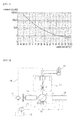
Fig. 2 is a graph explaining the relationship between hydraulic fluid temperature of hydraulic fluid that is used in a hydraulic system for a construction machine and viscosity; -
Fig. 3 is a hydraulic circuit diagram of a hydraulic system for a construction machine having a protection device according to a first preferred embodiment of the present invention; -
Fig. 4 is a diagram explaining the displacement volume control characteristic of a hydraulic pump in a hydraulic system for a construction machine having a protection device according to a first preferred embodiment of the present invention; -
Fig. 5 is a flowchart explaining displacement volume control of a hydraulic pump in a hydraulic system for a construction machine having a protection device according to a first preferred embodiment of the present invention; -
Fig. 6 is a flowchart explaining engine revolution control in a hydraulic system for a construction machine having a protection device according to a second preferred embodiment of the present invention; and -
Fig. 7 is a flowchart explaining input torque control of a hydraulic pump in a hydraulic system for a construction machine having a protection device according to a second preferred embodiment of the present invention. -
- 11: engine
- 12: hydraulic pump
- 13: hydraulic actuator
- 14: control valve (MCV)
- 15: hydraulic fluid tank
- 16: return flow path
- 17: oil cooler
- 18: hydraulic pump regulator
- 19: controller
- 20: hydraulic fluid temperature sensor
- Hereinafter, a hydraulic system for a construction machine having a protection device in accordance with preferred embodiments of the present invention will be described in detail with reference to the accompanying drawings.
-
Fig. 3 is a hydraulic circuit diagram of a hydraulic system for a construction machine having a protection device according to a first preferred embodiment of the present invention, andFig. 4 is a diagram explaining the displacement volume control characteristic of a hydraulic pump in a hydraulic system for a construction machine having a protection device according to a first preferred embodiment of the present invention.Fig. 5 is a flowchart explaining displacement volume control of a hydraulic pump in a hydraulic system for a construction machine having a protection device according to a first preferred embodiment of the present invention,Fig. 6 is a flowchart explaining engine revolution control in a hydraulic system for a construction machine having a protection device according to a second preferred embodiment of the present invention, andFig. 7 is a flowchart explaining input torque control of a hydraulic pump in a hydraulic system for a construction machine having a protection device according to a second preferred embodiment of the present invention. - Referring to
Figs. 3 to 5 , a hydraulic system for a construction machine having a protection device according to a first embodiment of the present invention includes a variable displacement hydraulic pump 2 (hereinafter referred to as "hydraulic pump") operated by an engine 1; a hydraulic actuator 3 (e.g., boom cylinder) operated by hydraulic fluid that is supplied from thehydraulic pump 2; a control valve (MCV) 14 installed in a flow path between thehydraulic pump 12 and thehydraulic actuator 13 to control a flow rate of the hydraulic fluid that is supplied from thehydraulic pump 12 to thehydraulic actuator 13; anoil cooler 17 installed in areturn flow path 16 from thecontrol valve 14 to ahydraulic fluid tank 15 to cool the hydraulic fluid that returns to thehydraulic fluid tank 15; a hydraulicfluid temperature sensor 20 detecting in real time a hydraulic fluid temperature of thehydraulic fluid tank 15; ahydraulic pump regulator 18 controlling a discharge flow rate of thehydraulic pump 12 through adjustment of an inclination angle of a swash plate of thehydraulic pump 12; and acontroller 19 comparing the hydraulic fluid temperature that is detected by the hydraulicfluid temperature sensor 20 with a predetermined hydraulic fluid temperature, and outputting a control signal for controlling a displacement volume of thehydraulic pump 12 to thehydraulic pump regulator 18 so as to limit the discharge flow rate of thehydraulic pump 12 to or below a predetermined flow rate if the detected hydraulic fluid temperature is equal to or lower than a predetermined lower limit value, or equal to or higher than a predetermined upper limit value. - The
controller 19 may include a control means (not illustrated) for controlling the discharge flow rate of thehydraulic pump 12 in accordance with the hydraulic fluid temperature detected by the hydraulicfluid temperature sensor 20, checking the hydraulic fluid temperature in real time, and releasing the function of limiting the discharge flow rate of thehydraulic pump 12 to or below the predetermined flow rate if the detected hydraulic fluid temperature belongs to a certain temperature range between the lower limit value and the upper limit value. - The
controller 19 may include a warning means (not illustrated) for notifying an operator on an operator's seat of information on the hydraulic fluid temperature if the detected hydraulic fluid temperature, which is input from the hydraulic fluid temperature sensor (20) to thecontroller 19, is equal to or lower than the predetermined lower limit value, or equal to or higher than the predetermined upper limit value. - Any one of an alarm, a buzzer, and a sound message may be used as the warning means.
- According to the hydraulic system for a construction machine according to the first embodiment of the present invention as described above, the hydraulic fluid temperature of the
hydraulic fluid tank 15 is detected by the hydraulicfluid temperature sensor 20, and the detected hydraulic fluid temperature value is output to the controller 19 (S10). - At S20, the hydraulic fluid temperature that is input to the
controller 19 and the predetermined hydraulic fluid temperature are compared with each other. If the detected hydraulic fluid temperature is equal to or higher than the predetermined lower limit value, the processing proceeds to S30, whereas if the detected hydraulic fluid temperature is lower than the predetermined lower limit value, the processing proceeds to S50. - At S30, the hydraulic fluid temperature that is input to the
controller 19 and the predetermined hydraulic fluid temperature are compared with each other. If the hydraulic fluid temperature that is detected by the hydraulicfluid temperature sensor 20 is equal to or lower than the predetermined upper limit value, the processing proceeds to S40, whereas if the hydraulic fluid temperature that is detected by the hydraulicfluid temperature sensor 20 is higher than the predetermined upper limit value, the processing proceeds to S50. - At S40, if the hydraulic fluid temperature that is input to the
controller 19 belongs to a certain temperature range between the predetermined lower limit value and the predetermined upper limit value, thecontroller 19 determines that the hydraulic fluid temperature of the hydraulic fluid is at a normal level. Accordingly, the hydraulic fluid of thehydraulic pump 12 is discharged with the predetermined flow rate corresponding to the control signal that is input from thecontroller 19 to thehydraulic pump regulator 18. - At S50, if the hydraulic fluid temperature that is input to the
controller 19 is equal to or lower than the predetermined lower limit value (S20) or is equal to or higher than the predetermined upper limit value (S30), thecontroller 19 determines that the hydraulic fluid temperature of the hydraulic fluid deviates from the normal level. Accordingly, if the hydraulic fluid temperature that is input to thecontroller 19 is equal to or lower than the predetermined lower limit value, the inclination angle of the swash plate of thehydraulic pump 12 is limited by the control signal that is input from thecontroller 19 to thehydraulic pump regulator 18 to limit the displacement volume thereof. Through this, the discharge flow rate of thehydraulic pump 12 is limited to or below the predetermined flow rate until the hydraulic fluid temperature that is detected in real time by the hydraulicfluid temperature sensor 20 to be input to thecontroller 19 exceeds the predetermined lower limit value. - Further, even if the hydraulic fluid temperature that is input to the
controller 19 is equal to or higher than the predetermined upper limit value, the inclination angle of the swash plate of thehydraulic pump 12 is limited by the control signal that is input from thecontroller 19 to thehydraulic pump regulator 18 to limit the displacement volume thereof (the displacement volume of thehydraulic pump 12 is reduced other than being in proportion to the applied pilot signal as shown inFig. 4 ). Through this, the discharge flow rate of thehydraulic pump 12 is limited to or below the predetermined flow rate until the hydraulic fluid temperature that is detected in real time by the hydraulicfluid temperature sensor 20 to be input to thecontroller 19 becomes lower than the predetermined upper limit value. - As described above, in the case where the hydraulic fluid temperature that is detected by the hydraulic
fluid temperature sensor 20 to be input to thecontroller 19 is equal to or lower than the predetermined lower limit value, or equal to or higher than the predetermined upper limit value, the discharge flow rate of thehydraulic pump 12 can be limited to the predetermined flow rate through limiting of the displacement volume of thehydraulic pump 12. At the same time, an operator on an operator's seat is notified of information on the hydraulic fluid temperature. Through this, the operator determines that the hydraulic fluid temperature of the hydraulic fluid deviates from the normal level, and thus can take proper safety measures to protect the hydraulic system. - Referring to
Figs. 3 and6 , a hydraulic system for a construction machine having a protection device according to a second embodiment of the present invention includes a variable displacement hydraulic pump 2 (hereinafter referred to as "hydraulic pump") operated by an engine 1; a hydraulic actuator 3 (e.g., boom cylinder) operated by hydraulic fluid that is supplied from thehydraulic pump 2; a control valve (MCV) 14 installed in a flow path between thehydraulic pump 12 and thehydraulic actuator 13 to control a flow rate of the hydraulic fluid that is supplied from thehydraulic pump 12 to thehydraulic actuator 13; anoil cooler 17 installed in areturn flow path 16 from thecontrol valve 14 to ahydraulic fluid tank 15 to cool the hydraulic fluid that returns to thehydraulic fluid tank 15; a hydraulicfluid temperature sensor 20 detecting in real time a hydraulic fluid temperature of thehydraulic fluid tank 15; ahydraulic pump regulator 18 controlling a discharge flow rate of thehydraulic pump 12 through adjustment of an inclination angle of a swash plate of thehydraulic pump 12; and acontroller 19 comparing the hydraulic fluid temperature that is detected by the hydraulicfluid temperature sensor 20 with a predetermined hydraulic fluid temperature, and outputting a control signal to an engine revolution control device of theengine 11 so as to limit the discharge flow rate of thehydraulic pump 12 to or below a predetermined flow rate through adjustment of an engine revolution of theengine 11 if the detected hydraulic fluid temperature is equal to or lower than a predetermined lower limit value, or equal to or higher than a predetermined upper limit value. - In this case, since the configuration, except for the
controller 19 outputting the control signal to the engine revolution control device of theengine 11 so as to limit the discharge flow rate of thehydraulic pump 12 to or below the predetermined flow rate through adjustment of the engine revolution of theengine 11 if the detected hydraulic fluid temperature is equal to or lower than the predetermined lower limit value, or equal to or higher than the predetermined upper limit value, is the same as the configuration of the hydraulic system for a construction machine having a protection device according to the first embodiment of the present invention, the detailed explanation thereof will be omitted. - According to the hydraulic system for a construction machine according to the second embodiment of the present invention as described above, the hydraulic fluid temperature of the
hydraulic fluid tank 15 is detected by the hydraulicfluid temperature sensor 20, and the detected hydraulic fluid temperature value is output to the controller 19 (S100). - At S200, the hydraulic fluid temperature that is input to the
controller 19 and the predetermined hydraulic fluid temperature are compared with each other. If the hydraulic fluid temperature that is detected by the hydraulicfluid temperature sensor 20 is equal to or higher than the predetermined lower limit value, the processing proceeds to S300, whereas if the hydraulic fluid temperature that is detected by the hydraulicfluid temperature sensor 20 is lower than the predetermined lower limit value, the processing proceeds to S500. - At S300, the hydraulic fluid temperature that is input to the
controller 19 and the predetermined hydraulic fluid temperature are compared with each other. If the hydraulic fluid temperature that is detected by the hydraulicfluid temperature sensor 20 is equal to or lower than the predetermined upper limit value, the processing proceeds to S400, whereas if the hydraulic fluid temperature that is detected by the hydraulicfluid temperature sensor 20 is higher than the predetermined upper limit value, the processing proceeds to S500. - At S400, if the hydraulic fluid temperature that is input to the
controller 19 belongs to a certain temperature range between the predetermined lower limit value and the predetermined upper limit value, thecontroller 19 determines that the hydraulic fluid temperature of the hydraulic fluid is at a normal level. Accordingly, the hydraulic fluid of thehydraulic pump 12 is discharged with the predetermined flow rate corresponding to the control signal that is input from thecontroller 19 to thehydraulic pump regulator 18. - At S500, if the hydraulic fluid temperature that is input to the
controller 19 is equal to or lower than the predetermined lower limit value (S200) or is equal to or higher than the predetermined upper limit value (S300), thecontroller 19 determines that the hydraulic fluid temperature of the hydraulic fluid deviates from the normal level. Accordingly, if the hydraulic fluid temperature that is input to thecontroller 19 is equal to or lower than the predetermined lower limit value, the engine revolution of theengine 11 is lowered by the control signal that is input from thecontroller 19 to the engine revolution control device so as to limit the discharge flow rate of thehydraulic pump 12 through the adjustment of the engine revolution. Through this, the discharge flow rate of thehydraulic pump 12 is limited to or below the predetermined flow rate until the hydraulic fluid temperature that is detected in real time by the hydraulicfluid temperature sensor 20 to be input to thecontroller 19 exceeds the predetermined lower limit value. - Further, even if the hydraulic fluid temperature that is input to the
controller 19 is equal to or higher than the predetermined upper limit value, the revolution of theengine 11 is lowered by the control signal that is input from thecontroller 19 to the engine revolution control device so as to limit the discharge flow rate of thehydraulic pump 12 through adjustment of the engine revolution. Through this, the discharge flow rate of thehydraulic pump 12 is limited to or below the predetermined flow rate until the hydraulic fluid temperature that is detected in real time by the hydraulicfluid temperature sensor 20 to be input to thecontroller 19 becomes lower than the predetermined upper limit value. - As described above, in the case where the hydraulic fluid temperature that is detected by the hydraulic
fluid temperature sensor 20 to be input to thecontroller 19 is equal to or lower than the predetermined lower limit value, or equal to or higher than the predetermined upper limit value, the discharge flow rate of thehydraulic pump 12 can be limited to the predetermined flow rate by lowering the revolution of theengine 11 through control of the engine revolution control device. At the same time, since the operator on the operator's seat is notified of the information on the hydraulic fluid temperature, the operator can take proper safety measures. - Referring to
Figs. 3 and7 , a hydraulic system for a construction machine having a protection device according to a third embodiment of the present invention includes a variable displacement hydraulic pump 2 (hereinafter referred to as "hydraulic pump") operated by an engine 1; a hydraulic actuator 3 (e.g., boom cylinder) operated by hydraulic fluid that is supplied from the hydraulic pump 2; a control valve (MCV) 14 installed in a flow path between the hydraulic pump 12 and the hydraulic actuator 13 to control a flow rate of the hydraulic fluid that is supplied from the hydraulic pump 12 to the hydraulic actuator 13; an oil cooler 17 installed in a return flow path 16 from the control valve 14 to a hydraulic fluid tank 15 to cool the hydraulic fluid that returns to the hydraulic fluid tank 15; a hydraulic fluid temperature sensor 20 detecting in real time a hydraulic fluid temperature of the hydraulic fluid tank 15; a hydraulic pump regulator 18 controlling a discharge flow rate of the hydraulic pump 12 through adjustment of an inclination angle of a swash plate of the hydraulic pump 12; a pressure detection sensor (not illustrated) detecting pressure of the hydraulic pump 12; a flow rate detection sensor (not illustrated) detecting the discharge flow rate of the hydraulic pump 12; and a controller 19 comparing the hydraulic fluid temperature that is detected by the hydraulic fluid temperature sensor 20 with a predetermined hydraulic fluid temperature, calculating a torque in accordance with the detected discharge flow rate and pressure of the hydraulic pump 12 if the detected hydraulic fluid temperature is equal to or lower than a predetermined lower limit value, or equal to or higher than a predetermined upper limit value, and outputting a control signal to a hydraulic pump torque control device (not illustrated) that is provided in the hydraulic pump regulator 18 so as to limit the discharge flow rate of the hydraulic pump 12 to or below a predetermined flow rate through reduction of an input torque value of the hydraulic pump 12 against the calculated torque value with a predetermined ratio. - In this case, since the configuration, except for the
controller 19 calculating the torque in accordance with the detected discharge flow rate and pressure of thehydraulic pump 12 if the hydraulic fluid temperature that is detected by the hydraulicfluid temperature sensor 20 is equal to or lower than the predetermined lower limit value, or equal to or higher than the predetermined upper limit value, and outputting the control signal to thehydraulic pump regulator 18 so as to limit the discharge flow rate of thehydraulic pump 12 to or below the predetermined flow rate through reduction of the input torque value of thehydraulic pump 12 against the calculated torque value with the predetermined ratio, is the same as the configuration of the hydraulic system for a construction machine having a protection device according to the first embodiment of the present invention, the detailed explanation thereof will be omitted. - According to the hydraulic system for a construction machine according to the third embodiment of the present invention as described above, the hydraulic fluid temperature of the
hydraulic fluid tank 15 is detected by the hydraulicfluid temperature sensor 20, and the detected hydraulic fluid temperature value is output to thecontroller 19. Further, the pressure and the flow rate of the hydraulic pump are detected by the pressure detection sensor and the flow rate detection sensor, and the detected values are output to the controller 19 (S1000). - At S2000, the hydraulic fluid temperature that is input to the
controller 19 and the predetermined hydraulic fluid temperature are compared with each other. If the hydraulic fluid temperature that is detected by the hydraulicfluid temperature sensor 20 is equal to or higher than the predetermined lower limit value, the processing proceeds to S3000, whereas if the hydraulic fluid temperature that is detected by the hydraulicfluid temperature sensor 20 is lower than the predetermined lower limit value, the processing proceeds to S5000. - At S3000, the hydraulic fluid temperature that is input to the
controller 19 and the predetermined hydraulic fluid temperature are compared with each other. If the hydraulic fluid temperature that is detected by the hydraulicfluid temperature sensor 20 is equal to or lower than the predetermined upper limit value, the processing proceeds to S4000, whereas if the hydraulic fluid temperature that is detected by the hydraulicfluid temperature sensor 20 is higher than the predetermined upper limit value, the processing proceeds to S5000. - At S4000, if the hydraulic fluid temperature that is input to the
controller 19 belongs to a certain temperature range between the predetermined lower limit value and the predetermined upper limit value, thecontroller 19 determines that the hydraulic fluid temperature of the hydraulic fluid is at a normal level. Accordingly, thecontroller 19 calculates the torque in accordance with the discharge flow rate and the pressure of thehydraulic pump 12 that are detected by the pressure detection sensor and the flow rate detection sensor, and outputs the control signal according to the calculated torque value to the hydraulic pump regulator so as to limit the discharge flow rate of thehydraulic pump 12 to the predetermined flow rate. - At S5000, if the hydraulic fluid temperature that is input to the
controller 19 is equal to or lower than the predetermined lower limit value (S2000) or is equal to or higher than the predetermined upper limit value (S3000), thecontroller 19 determines that the hydraulic fluid temperature of the hydraulic fluid deviates from the normal level. Accordingly, if the hydraulic fluid temperature that is input to thecontroller 19 is equal to or lower than the predetermined lower limit value, thecontroller 19 calculates the torque in accordance with the discharge flow rate and the pressure of thehydraulic pump 12 that are detected by the pressure detection sensor and the flow rate detection sensor. Thecontroller 19 outputs the control signal according to the corrected input torque value to thehydraulic pump regulator 18 through reduction of the input torque value of thehydraulic pump 12 against the calculated torque value to the predetermined rate. Through this, the discharge flow rate of thehydraulic pump 12 is limited to or below the predetermined flow rate until the hydraulic fluid temperature that is detected in real time by the hydraulicfluid temperature sensor 20 to be input to thecontroller 19 exceeds the predetermined lower limit value. - Further, even if the hydraulic fluid temperature that is input to the
controller 19 is equal to or higher than the predetermined upper limit value, thecontroller 19 calculates the torque in accordance with the discharge flow rate and the pressure of thehydraulic pump 12 that are detected by the pressure detection sensor and the flow rate detection sensor. Thecontroller 19 outputs the control signal according to the corrected input torque value to thehydraulic pump regulator 18 through reduction of the input torque value of thehydraulic pump 12 against the calculated torque value to the predetermined rate. Through this, the discharge flow rate of thehydraulic pump 12 is limited to or below the predetermined flow rate until the hydraulic fluid temperature that is detected in real time by the hydraulicfluid temperature sensor 20 to be input to thecontroller 19 exceeds the predetermined lower limit value. - As described above, in the case where the hydraulic fluid temperature that is detected by the hydraulic
fluid temperature sensor 20 to be input to thecontroller 19 is equal to or lower than the predetermined lower limit value, or equal to or higher than the predetermined upper limit value, the discharge flow rate of thehydraulic pump 12 can be limited to the predetermined flow rate by lowering the input torque of thehydraulic pump 12. At the same time, since the operator on the operator's seat is notified of the information on the hydraulic fluid temperature, the operator can take proper safety measures. - Although the present invention has been described with reference to the preferred embodiments in the attached figures, it is noted that equivalents may be employed and substitutions made herein without departing from the scope of the invention as recited in the claims.
- According to the present invention having the above-described configuration, since the flow rate of the hydraulic fluid that is discharged from the hydraulic pump is limited in accordance with the hydraulic fluid temperature, the hydraulic system of the equipment can be prevented from being damaged, and the oil leak can be prevented. Further, since the operator is warned this, the operator can take proper safety measures to protect the hydraulic system.
- While the present invention has been described in connection with the specific embodiments illustrated in the drawings, they are merely illustrative, and the invention is not limited to these embodiments. It is to be understood that various equivalent modifications and variations of the embodiments can be made by a person having an ordinary skill in the art without departing from the spirit and scope of the present invention. Therefore, the true technical scope of the present invention should not be defined by the above-mentioned embodiments but should be defined by the appended claims and equivalents thereof.
Claims (10)
- A hydraulic system for a construction machine having a protection device, comprising:a variable displacement hydraulic pump;a hydraulic actuator operated by hydraulic fluid that is supplied from the hydraulic pump;a control valve installed in a flow path between the hydraulic pump and the hydraulic actuator to control a flow rate of the hydraulic fluid that is supplied from the hydraulic pump to the hydraulic actuator;an oil cooler installed in a return flow path from the control valve to a hydraulic fluid tank to cool the hydraulic fluid;a hydraulic fluid temperature sensor detecting in real time a hydraulic fluid temperature of the hydraulic fluid tank;a hydraulic pump regulator controlling a discharge flow rate of the hydraulic pump through adjustment of an inclination angle of a swash plate of the hydraulic pump; anda controller comparing the hydraulic fluid temperature detected by the hydraulic fluid temperature sensor with a predetermined hydraulic fluid temperature, and outputting a control signal to the hydraulic pump regulator so as to limit the discharge flow rate of the hydraulic pump to or below a predetermined flow rate if the detected hydraulic fluid temperature is equal to or lower than a predetermined lower limit value, or equal to or higher than a predetermined upper limit value.
- A hydraulic system for a construction machine having a protection device, comprising:a variable displacement hydraulic pump operated by an engine;a hydraulic actuator operated by hydraulic fluid that is supplied from the hydraulic pump;a control valve installed in a flow path between the hydraulic pump and the hydraulic actuator to control a flow rate of the hydraulic fluid that is supplied from the hydraulic pump to the hydraulic actuator;an oil cooler installed in a return flow path from the control valve to a hydraulic fluid tank to cool the hydraulic fluid;a hydraulic fluid temperature sensor detecting in real time a hydraulic fluid temperature of the hydraulic fluid tank;a hydraulic pump regulator controlling a discharge flow rate of the hydraulic pump through adjustment of an inclination angle of a swash plate of the hydraulic pump; anda controller comparing the hydraulic fluid temperature detected by the hydraulic fluid temperature sensor with a predetermined hydraulic fluid temperature, and outputting a control signal to an engine revolution control device of the engine so as to limit the discharge flow rate of the hydraulic pump to or below a predetermined flow rate through adjustment of an engine revolution of the engine if the detected hydraulic fluid temperature is equal to or lower than a predetermined lower limit value, or equal to or higher than a predetermined upper limit value.
- A hydraulic system for a construction machine having a protection device, comprising:a variable displacement hydraulic pump;a hydraulic actuator operated by hydraulic fluid that is supplied from the hydraulic pump;a control valve installed in a flow path between the hydraulic pump and the hydraulic actuator to control a flow rate of the hydraulic fluid that is supplied from the hydraulic pump to the hydraulic actuator;an oil cooler installed in a return flow path from the control valve to a hydraulic fluid tank to cool the hydraulic fluid;a hydraulic fluid temperature sensor detecting in real time a hydraulic fluid temperature of the hydraulic fluid tank;a hydraulic pump regulator controlling a discharge flow rate of the hydraulic pump through adjustment of an inclination angle of a swash plate of the hydraulic pump;a pressure detection sensor detecting pressure of the hydraulic pump;a flow rate detection sensor detecting the discharge flow rate of the hydraulic pump; anda controller comparing the hydraulic fluid temperature detected by the hydraulic fluid temperature sensor with a predetermined hydraulic fluid temperature, calculating a torque in accordance with the detected discharge flow rate and pressure of the hydraulic pump if the detected hydraulic fluid temperature is equal to or lower than a predetermined lower limit value, or equal to or higher than a predetermined upper limit value, and outputting a control signal to the hydraulic pump regulator so as to limit the discharge flow rate of the hydraulic pump to or below a predetermined flow rate through reduction of an input torque value of the hydraulic pump against the calculated torque value with a predetermined ratio.
- The hydraulic system according to claim 1, wherein the controller comprises a control means for controlling the discharge flow rate of the hydraulic pump in accordance with the hydraulic fluid temperature detected by the hydraulic fluid temperature sensor, checking the hydraulic fluid temperature in real time, and releasing the function of limiting the discharge flow rate of the hydraulic pump to or below the predetermined flow rate if the detected hydraulic fluid temperature belongs to a certain temperature range between the lower limit value and the upper limit value.
- The hydraulic system according to claim 1, wherein the controller comprises a warning means for notifying an operator on an operator's seat of information on the hydraulic fluid temperature if the detected hydraulic fluid temperature, which is input from the hydraulic fluid temperature sensor to the controller, is equal to or lower than the predetermined lower limit value, or equal to or higher than the predetermined upper limit value.
- The hydraulic system according to claim 2, wherein the controller comprises a control means for controlling the discharge flow rate of the hydraulic pump in accordance with the hydraulic fluid temperature detected by the hydraulic fluid temperature sensor, checking the hydraulic fluid temperature in real time, and releasing the function of limiting the discharge flow rate of the hydraulic pump to or below the predetermined flow rate if the detected hydraulic fluid temperature belongs to a certain temperature range between the lower limit value and the upper limit value.
- The hydraulic system according to claim 2, wherein the controller comprises a warning means for notifying an operator on an operator's seat of information on the hydraulic fluid temperature if the detected hydraulic fluid temperature, which is input from the hydraulic fluid temperature sensor to the controller, is equal to or lower than the predetermined lower limit value, or equal to or higher than the predetermined upper limit value.
- The hydraulic system according to claim 3, wherein the controller comprises a control means for controlling the discharge flow rate of the hydraulic pump in accordance with the hydraulic fluid temperature detected by the hydraulic fluid temperature sensor, checking the hydraulic fluid temperature in real time, and releasing the function of limiting the discharge flow rate of the hydraulic pump to or below the predetermined flow rate if the detected hydraulic fluid temperature belongs to a certain temperature range between the lower limit value and the upper limit value.
- The hydraulic system according to claim 3, wherein the controller comprises a warning means for notifying an operator on an operator's seat of information on the hydraulic fluid temperature if the detected hydraulic fluid temperature, which is input from the hydraulic fluid temperature sensor to the controller, is equal to or lower than the predetermined lower limit value, or equal to or higher than the predetermined upper limit value.
- The hydraulic system according to any one of claims 5, 7, or 9, wherein any one of an alarm, a buzzer, and a sound message is used as the warning means.
Applications Claiming Priority (1)
| Application Number | Priority Date | Filing Date | Title |
|---|---|---|---|
| PCT/KR2013/001286 WO2014129676A1 (en) | 2013-02-19 | 2013-02-19 | Hydraulic system for construction machine, provided with protection device |
Publications (3)
| Publication Number | Publication Date |
|---|---|
| EP2960529A1 true EP2960529A1 (en) | 2015-12-30 |
| EP2960529A4 EP2960529A4 (en) | 2016-11-23 |
| EP2960529B1 EP2960529B1 (en) | 2019-01-02 |
Family
ID=51391448
Family Applications (1)
| Application Number | Title | Priority Date | Filing Date |
|---|---|---|---|
| EP13875723.2A Active EP2960529B1 (en) | 2013-02-19 | 2013-02-19 | Hydraulic system for construction machine, provided with protection device |
Country Status (5)
| Country | Link |
|---|---|
| US (1) | US9790965B2 (en) |
| EP (1) | EP2960529B1 (en) |
| KR (1) | KR20150136053A (en) |
| CN (1) | CN104981615B (en) |
| WO (1) | WO2014129676A1 (en) |
Cited By (3)
| Publication number | Priority date | Publication date | Assignee | Title |
|---|---|---|---|---|
| CN109667309A (en) * | 2017-10-16 | 2019-04-23 | 迪尔公司 | The hydraulic reduction of temperature-responsive |
| WO2020180923A1 (en) * | 2019-03-05 | 2020-09-10 | Danfoss Power Solutions, Inc. | Method for determining the health status of the hydraulic circuit arrangement |
| AT524855A4 (en) * | 2021-06-18 | 2022-10-15 | Weber Hydraulik Gmbh | Hydraulic unit for supplying hydraulically driven rescue equipment |
Families Citing this family (14)
| Publication number | Priority date | Publication date | Assignee | Title |
|---|---|---|---|---|
| KR102054520B1 (en) * | 2013-03-21 | 2020-01-22 | 두산인프라코어 주식회사 | Control method for Hydraulic system of Construction machinery |
| JP2015086710A (en) * | 2013-10-28 | 2015-05-07 | 株式会社日立製作所 | Centrifugal compressor for gas pipeline and gas pipeline |
| KR20170084813A (en) * | 2016-01-13 | 2017-07-21 | 두산인프라코어 주식회사 | Warming up system for construction machinery and control method for construction machinery using the same |
| CN112469868B (en) | 2018-07-25 | 2023-05-23 | 克拉克设备公司 | Hydraulic oil temperature management for power machines |
| CN110091703B (en) * | 2019-05-31 | 2021-03-09 | 吉林大学 | A pump displacement limitation method for the limit state of a wheel hub hydraulic drive system |
| CN110409542B (en) * | 2019-06-28 | 2021-08-24 | 三一重机有限公司 | Excavator control method, device and excavator |
| EP3967880B1 (en) * | 2019-11-08 | 2024-03-20 | Hitachi Construction Machinery Co., Ltd. | Hydraulic actuator control device for dump truck |
| CN110822831B (en) * | 2019-11-16 | 2020-10-02 | 安徽翰联色纺股份有限公司 | Constant temperature drying cabinet of yarn weaving usefulness convenient to heat dissipation |
| CN112032145B (en) * | 2020-11-03 | 2021-01-26 | 山东交通职业学院 | Hydraulic system for engineering machinery provided with protection device |
| IT202100011201A1 (en) * | 2021-05-03 | 2022-11-03 | Cnh Ind Italia Spa | AUTOMATIC HEATING SYSTEM FOR A HYDRAULIC CIRCUIT OF A WORK VEHICLE |
| US12280382B2 (en) * | 2021-06-24 | 2025-04-22 | Elgin Separation Solutions Industrials, Llc | Electronically controlled hydraulic decanter centrifuge |
| FI4155501T3 (en) * | 2021-09-24 | 2024-05-16 | Sandvik Mining & Construction Oy | HYDRAULIC SYSTEM, ROCK DRILLING EQUIPMENT AND METHOD EQUIPPED WITH A SAFETY STATUS |
| JP7848483B2 (en) * | 2022-01-19 | 2026-04-21 | コベルコ建機株式会社 | Oil abnormality detection system, oil abnormality detection method, and oil abnormality detection program |
| CN119222210B (en) * | 2024-11-29 | 2025-03-14 | 江苏月仙智能装备有限公司 | Hydraulic powered cold storage door with hydraulic temperature monitoring and control function |
Family Cites Families (20)
| Publication number | Priority date | Publication date | Assignee | Title |
|---|---|---|---|---|
| JP2735978B2 (en) * | 1992-04-02 | 1998-04-02 | 日立建機株式会社 | Hydraulic construction machine torque control device |
| KR0152300B1 (en) | 1993-07-02 | 1998-10-15 | 김연수 | Control method of discharge flow rate of hydraulic pump |
| US5564274A (en) * | 1995-12-13 | 1996-10-15 | Caterpillar Inc. | Cold oil protection circuit for a hydraulic system |
| JP2001041204A (en) * | 1999-07-27 | 2001-02-13 | Sumitomo Constr Mach Co Ltd | Hydraulic circuit |
| JP3775245B2 (en) * | 2001-06-11 | 2006-05-17 | コベルコ建機株式会社 | Pump controller for construction machinery |
| JP4542819B2 (en) * | 2004-05-21 | 2010-09-15 | 株式会社小松製作所 | Hydraulic machine, system and method for monitoring the health status of a hydraulic machine |
| KR100631071B1 (en) * | 2005-04-20 | 2006-10-02 | 볼보 컨스트럭션 이키프먼트 홀딩 스웨덴 에이비 | Pump flow control device for construction machinery and its control method |
| JP5084295B2 (en) * | 2007-02-09 | 2012-11-28 | 日立建機株式会社 | Pump torque control device for hydraulic construction machinery |
| JP5064843B2 (en) * | 2007-03-08 | 2012-10-31 | 株式会社小松製作所 | Work equipment pump rotation control system |
| JP2010270647A (en) * | 2009-05-20 | 2010-12-02 | Hitachi Constr Mach Co Ltd | Warm-up device for construction machine |
| KR101032731B1 (en) * | 2009-06-02 | 2011-05-06 | 볼보 컨스트럭션 이큅먼트 에이비 | Hydraulic system for excavators with hammer device |
| CN102893035B (en) | 2010-06-24 | 2015-09-30 | 沃尔沃建造设备有限公司 | Hydraulic pump control system for construction machinery |
| WO2012002586A1 (en) | 2010-06-28 | 2012-01-05 | 볼보 컨스트럭션 이큅먼트 에이비 | Flow control system for a hydraulic pump of construction machinery |
| WO2012011615A1 (en) | 2010-07-19 | 2012-01-26 | 볼보 컨스트럭션 이큅먼트 에이비 | System for controlling hydraulic pump in construction machine |
| CN101900153B (en) * | 2010-08-23 | 2012-07-11 | 西安建筑科技大学 | Energy-saving hydraulic power source driven by permanent magnet servo motor |
| CN101974926A (en) * | 2010-09-29 | 2011-02-16 | 三一重机有限公司 | Oil returning system capable of automatically controlling hydraulic oil temperature used for excavator |
| EP2644905A4 (en) | 2010-11-25 | 2018-01-10 | Volvo Construction Equipment AB | Flow control valve for construction machine |
| EP2700827A4 (en) | 2011-04-19 | 2015-03-11 | Volvo Constr Equip Ab | Hydraulic circuit for controlling booms of construction equipment |
| US20140238010A1 (en) | 2011-10-07 | 2014-08-28 | Volvo Construction Equipment Ab | Control system for operating work device for construction machine |
| US20140325975A1 (en) | 2011-12-02 | 2014-11-06 | Volvo Construction Equipment Ab | Swing relief energy regeneration apparatus of an excavator |
-
2013
- 2013-02-19 KR KR1020157022029A patent/KR20150136053A/en not_active Ceased
- 2013-02-19 US US14/768,285 patent/US9790965B2/en active Active
- 2013-02-19 CN CN201380072836.6A patent/CN104981615B/en active Active
- 2013-02-19 WO PCT/KR2013/001286 patent/WO2014129676A1/en not_active Ceased
- 2013-02-19 EP EP13875723.2A patent/EP2960529B1/en active Active
Cited By (6)
| Publication number | Priority date | Publication date | Assignee | Title |
|---|---|---|---|---|
| CN109667309A (en) * | 2017-10-16 | 2019-04-23 | 迪尔公司 | The hydraulic reduction of temperature-responsive |
| CN109667309B (en) * | 2017-10-16 | 2022-05-31 | 迪尔公司 | Temperature responsive hydraulic pressure reduction |
| WO2020180923A1 (en) * | 2019-03-05 | 2020-09-10 | Danfoss Power Solutions, Inc. | Method for determining the health status of the hydraulic circuit arrangement |
| US11274684B2 (en) | 2019-03-05 | 2022-03-15 | Danfoss Power Solutions Inc. | Method for determining the health status of the hydraulic circuit arrangement |
| AT524855A4 (en) * | 2021-06-18 | 2022-10-15 | Weber Hydraulik Gmbh | Hydraulic unit for supplying hydraulically driven rescue equipment |
| AT524855B1 (en) * | 2021-06-18 | 2022-10-15 | Weber Hydraulik Gmbh | Hydraulic unit for supplying hydraulically driven rescue equipment |
Also Published As
| Publication number | Publication date |
|---|---|
| EP2960529B1 (en) | 2019-01-02 |
| WO2014129676A1 (en) | 2014-08-28 |
| US9790965B2 (en) | 2017-10-17 |
| CN104981615A (en) | 2015-10-14 |
| EP2960529A4 (en) | 2016-11-23 |
| KR20150136053A (en) | 2015-12-04 |
| US20160003265A1 (en) | 2016-01-07 |
| CN104981615B (en) | 2017-11-10 |
Similar Documents
| Publication | Publication Date | Title |
|---|---|---|
| EP2960529B1 (en) | Hydraulic system for construction machine, provided with protection device | |
| EP2597208B1 (en) | System for controlling hydraulic pump in construction machine | |
| US20170037790A1 (en) | Device for controlling engine and hydraulic pump of construction equipment and control method therefor | |
| EP2733362A1 (en) | Hydraulic actuator damping control system for construction machinery | |
| CN102720710B (en) | Hydraulic system, control method of hydraulic system and construction machinery | |
| US11608612B2 (en) | Hydraulic unit | |
| WO2010110021A1 (en) | Device for detecting abnormality in construction machine | |
| US9334630B2 (en) | All-round hazard sensing device for construction apparatus | |
| CA2915498A1 (en) | Device for controlling control valve of construction machine, method for controlling same, and method for controlling discharge flow rate of hydraulic pump | |
| JP2018009668A (en) | Construction machine | |
| JP2020051110A5 (en) | ||
| KR20100130034A (en) | Hydraulic system for excavators with hammer device | |
| CN107917114B (en) | Method for detecting non-commanded spool positioning and preventing fluid flow to a hydraulic actuator | |
| US20150059329A1 (en) | Hydraulic system for construction equipment | |
| CN104074843B (en) | Hydraulic device with the adjustable driving machine of revolving speed and for its control method | |
| EP3252237B1 (en) | Hydraulic control system | |
| US10202975B2 (en) | Method for determining cavitation in pumps | |
| EP3255215A1 (en) | Hydraulic pump control apparatus for construction equipment and control method thereof | |
| US10208458B2 (en) | Method for compensating for flow rate of hydraulic pump of construction machine | |
| CN102449295A (en) | Emulsion fuel supply device | |
| KR102169886B1 (en) | Control method of construction machine for overheat prevention | |
| CN103133459B (en) | Hydraulic system overflow warning method, overflow warning device and engineering machinery | |
| KR20260030898A (en) | Fluid device condition monitoring device | |
| KR20160053617A (en) | Apparatus and Method for detecting leak | |
| JP2017119964A (en) | Construction machinery |
Legal Events
| Date | Code | Title | Description |
|---|---|---|---|
| PUAI | Public reference made under article 153(3) epc to a published international application that has entered the european phase |
Free format text: ORIGINAL CODE: 0009012 |
|
| 17P | Request for examination filed |
Effective date: 20150812 |
|
| AK | Designated contracting states |
Kind code of ref document: A1 Designated state(s): AL AT BE BG CH CY CZ DE DK EE ES FI FR GB GR HR HU IE IS IT LI LT LU LV MC MK MT NL NO PL PT RO RS SE SI SK SM TR |
|
| AX | Request for extension of the european patent |
Extension state: BA ME |
|
| DAX | Request for extension of the european patent (deleted) | ||
| A4 | Supplementary search report drawn up and despatched |
Effective date: 20161024 |
|
| RIC1 | Information provided on ipc code assigned before grant |
Ipc: F15B 13/02 20060101ALI20161018BHEP Ipc: F15B 20/00 20060101AFI20161018BHEP Ipc: E02F 9/22 20060101ALI20161018BHEP Ipc: F15B 11/042 20060101ALN20161018BHEP |
|
| STAA | Information on the status of an ep patent application or granted ep patent |
Free format text: STATUS: EXAMINATION IS IN PROGRESS |
|
| 17Q | First examination report despatched |
Effective date: 20171013 |
|
| GRAP | Despatch of communication of intention to grant a patent |
Free format text: ORIGINAL CODE: EPIDOSNIGR1 |
|
| RIC1 | Information provided on ipc code assigned before grant |
Ipc: F15B 13/02 20060101ALI20180611BHEP Ipc: F15B 20/00 20060101AFI20180611BHEP Ipc: E02F 9/22 20060101ALI20180611BHEP Ipc: F15B 11/042 20060101ALN20180611BHEP |
|
| STAA | Information on the status of an ep patent application or granted ep patent |
Free format text: STATUS: GRANT OF PATENT IS INTENDED |
|
| INTG | Intention to grant announced |
Effective date: 20180719 |
|
| GRAS | Grant fee paid |
Free format text: ORIGINAL CODE: EPIDOSNIGR3 |
|
| GRAA | (expected) grant |
Free format text: ORIGINAL CODE: 0009210 |
|
| STAA | Information on the status of an ep patent application or granted ep patent |
Free format text: STATUS: THE PATENT HAS BEEN GRANTED |
|
| AK | Designated contracting states |
Kind code of ref document: B1 Designated state(s): AL AT BE BG CH CY CZ DE DK EE ES FI FR GB GR HR HU IE IS IT LI LT LU LV MC MK MT NL NO PL PT RO RS SE SI SK SM TR |
|
| REG | Reference to a national code |
Ref country code: GB Ref legal event code: FG4D |
|
| RIN1 | Information on inventor provided before grant (corrected) |
Inventor name: JOUNG, HEA-GYOON Inventor name: KIM, SUNG-GON |
|
| REG | Reference to a national code |
Ref country code: CH Ref legal event code: EP Ref country code: AT Ref legal event code: REF Ref document number: 1084745 Country of ref document: AT Kind code of ref document: T Effective date: 20190115 |
|
| REG | Reference to a national code |
Ref country code: IE Ref legal event code: FG4D |
|
| REG | Reference to a national code |
Ref country code: DE Ref legal event code: R096 Ref document number: 602013049390 Country of ref document: DE |
|
| REG | Reference to a national code |
Ref country code: NL Ref legal event code: MP Effective date: 20190102 |
|
| REG | Reference to a national code |
Ref country code: LT Ref legal event code: MG4D |
|
| REG | Reference to a national code |
Ref country code: AT Ref legal event code: MK05 Ref document number: 1084745 Country of ref document: AT Kind code of ref document: T Effective date: 20190102 |
|
| PG25 | Lapsed in a contracting state [announced via postgrant information from national office to epo] |
Ref country code: NL Free format text: LAPSE BECAUSE OF FAILURE TO SUBMIT A TRANSLATION OF THE DESCRIPTION OR TO PAY THE FEE WITHIN THE PRESCRIBED TIME-LIMIT Effective date: 20190102 |
|
| PG25 | Lapsed in a contracting state [announced via postgrant information from national office to epo] |
Ref country code: SE Free format text: LAPSE BECAUSE OF FAILURE TO SUBMIT A TRANSLATION OF THE DESCRIPTION OR TO PAY THE FEE WITHIN THE PRESCRIBED TIME-LIMIT Effective date: 20190102 Ref country code: PL Free format text: LAPSE BECAUSE OF FAILURE TO SUBMIT A TRANSLATION OF THE DESCRIPTION OR TO PAY THE FEE WITHIN THE PRESCRIBED TIME-LIMIT Effective date: 20190102 Ref country code: PT Free format text: LAPSE BECAUSE OF FAILURE TO SUBMIT A TRANSLATION OF THE DESCRIPTION OR TO PAY THE FEE WITHIN THE PRESCRIBED TIME-LIMIT Effective date: 20190502 Ref country code: NO Free format text: LAPSE BECAUSE OF FAILURE TO SUBMIT A TRANSLATION OF THE DESCRIPTION OR TO PAY THE FEE WITHIN THE PRESCRIBED TIME-LIMIT Effective date: 20190402 Ref country code: FI Free format text: LAPSE BECAUSE OF FAILURE TO SUBMIT A TRANSLATION OF THE DESCRIPTION OR TO PAY THE FEE WITHIN THE PRESCRIBED TIME-LIMIT Effective date: 20190102 Ref country code: ES Free format text: LAPSE BECAUSE OF FAILURE TO SUBMIT A TRANSLATION OF THE DESCRIPTION OR TO PAY THE FEE WITHIN THE PRESCRIBED TIME-LIMIT Effective date: 20190102 Ref country code: LT Free format text: LAPSE BECAUSE OF FAILURE TO SUBMIT A TRANSLATION OF THE DESCRIPTION OR TO PAY THE FEE WITHIN THE PRESCRIBED TIME-LIMIT Effective date: 20190102 |
|
| PG25 | Lapsed in a contracting state [announced via postgrant information from national office to epo] |
Ref country code: IS Free format text: LAPSE BECAUSE OF FAILURE TO SUBMIT A TRANSLATION OF THE DESCRIPTION OR TO PAY THE FEE WITHIN THE PRESCRIBED TIME-LIMIT Effective date: 20190502 Ref country code: HR Free format text: LAPSE BECAUSE OF FAILURE TO SUBMIT A TRANSLATION OF THE DESCRIPTION OR TO PAY THE FEE WITHIN THE PRESCRIBED TIME-LIMIT Effective date: 20190102 Ref country code: RS Free format text: LAPSE BECAUSE OF FAILURE TO SUBMIT A TRANSLATION OF THE DESCRIPTION OR TO PAY THE FEE WITHIN THE PRESCRIBED TIME-LIMIT Effective date: 20190102 Ref country code: LV Free format text: LAPSE BECAUSE OF FAILURE TO SUBMIT A TRANSLATION OF THE DESCRIPTION OR TO PAY THE FEE WITHIN THE PRESCRIBED TIME-LIMIT Effective date: 20190102 Ref country code: GR Free format text: LAPSE BECAUSE OF FAILURE TO SUBMIT A TRANSLATION OF THE DESCRIPTION OR TO PAY THE FEE WITHIN THE PRESCRIBED TIME-LIMIT Effective date: 20190403 Ref country code: BG Free format text: LAPSE BECAUSE OF FAILURE TO SUBMIT A TRANSLATION OF THE DESCRIPTION OR TO PAY THE FEE WITHIN THE PRESCRIBED TIME-LIMIT Effective date: 20190402 |
|
| REG | Reference to a national code |
Ref country code: CH Ref legal event code: PL |
|
| REG | Reference to a national code |
Ref country code: DE Ref legal event code: R097 Ref document number: 602013049390 Country of ref document: DE |
|
| PG25 | Lapsed in a contracting state [announced via postgrant information from national office to epo] |
Ref country code: AL Free format text: LAPSE BECAUSE OF FAILURE TO SUBMIT A TRANSLATION OF THE DESCRIPTION OR TO PAY THE FEE WITHIN THE PRESCRIBED TIME-LIMIT Effective date: 20190102 Ref country code: CZ Free format text: LAPSE BECAUSE OF FAILURE TO SUBMIT A TRANSLATION OF THE DESCRIPTION OR TO PAY THE FEE WITHIN THE PRESCRIBED TIME-LIMIT Effective date: 20190102 Ref country code: RO Free format text: LAPSE BECAUSE OF FAILURE TO SUBMIT A TRANSLATION OF THE DESCRIPTION OR TO PAY THE FEE WITHIN THE PRESCRIBED TIME-LIMIT Effective date: 20190102 Ref country code: IT Free format text: LAPSE BECAUSE OF FAILURE TO SUBMIT A TRANSLATION OF THE DESCRIPTION OR TO PAY THE FEE WITHIN THE PRESCRIBED TIME-LIMIT Effective date: 20190102 Ref country code: DK Free format text: LAPSE BECAUSE OF FAILURE TO SUBMIT A TRANSLATION OF THE DESCRIPTION OR TO PAY THE FEE WITHIN THE PRESCRIBED TIME-LIMIT Effective date: 20190102 Ref country code: AT Free format text: LAPSE BECAUSE OF FAILURE TO SUBMIT A TRANSLATION OF THE DESCRIPTION OR TO PAY THE FEE WITHIN THE PRESCRIBED TIME-LIMIT Effective date: 20190102 Ref country code: EE Free format text: LAPSE BECAUSE OF FAILURE TO SUBMIT A TRANSLATION OF THE DESCRIPTION OR TO PAY THE FEE WITHIN THE PRESCRIBED TIME-LIMIT Effective date: 20190102 Ref country code: LU Free format text: LAPSE BECAUSE OF NON-PAYMENT OF DUE FEES Effective date: 20190219 Ref country code: SK Free format text: LAPSE BECAUSE OF FAILURE TO SUBMIT A TRANSLATION OF THE DESCRIPTION OR TO PAY THE FEE WITHIN THE PRESCRIBED TIME-LIMIT Effective date: 20190102 Ref country code: MC Free format text: LAPSE BECAUSE OF FAILURE TO SUBMIT A TRANSLATION OF THE DESCRIPTION OR TO PAY THE FEE WITHIN THE PRESCRIBED TIME-LIMIT Effective date: 20190102 |
|
| PLBE | No opposition filed within time limit |
Free format text: ORIGINAL CODE: 0009261 |
|
| STAA | Information on the status of an ep patent application or granted ep patent |
Free format text: STATUS: NO OPPOSITION FILED WITHIN TIME LIMIT |
|
| REG | Reference to a national code |
Ref country code: BE Ref legal event code: MM Effective date: 20190228 |
|
| REG | Reference to a national code |
Ref country code: IE Ref legal event code: MM4A |
|
| PG25 | Lapsed in a contracting state [announced via postgrant information from national office to epo] |
Ref country code: SM Free format text: LAPSE BECAUSE OF FAILURE TO SUBMIT A TRANSLATION OF THE DESCRIPTION OR TO PAY THE FEE WITHIN THE PRESCRIBED TIME-LIMIT Effective date: 20190102 |
|
| 26N | No opposition filed |
Effective date: 20191003 |
|
| GBPC | Gb: european patent ceased through non-payment of renewal fee |
Effective date: 20190402 |
|
| PG25 | Lapsed in a contracting state [announced via postgrant information from national office to epo] |
Ref country code: LI Free format text: LAPSE BECAUSE OF NON-PAYMENT OF DUE FEES Effective date: 20190228 Ref country code: CH Free format text: LAPSE BECAUSE OF NON-PAYMENT OF DUE FEES Effective date: 20190228 |
|
| PG25 | Lapsed in a contracting state [announced via postgrant information from national office to epo] |
Ref country code: GB Free format text: LAPSE BECAUSE OF NON-PAYMENT OF DUE FEES Effective date: 20190402 Ref country code: IE Free format text: LAPSE BECAUSE OF NON-PAYMENT OF DUE FEES Effective date: 20190219 |
|
| PG25 | Lapsed in a contracting state [announced via postgrant information from national office to epo] |
Ref country code: BE Free format text: LAPSE BECAUSE OF NON-PAYMENT OF DUE FEES Effective date: 20190228 Ref country code: SI Free format text: LAPSE BECAUSE OF FAILURE TO SUBMIT A TRANSLATION OF THE DESCRIPTION OR TO PAY THE FEE WITHIN THE PRESCRIBED TIME-LIMIT Effective date: 20190102 |
|
| PG25 | Lapsed in a contracting state [announced via postgrant information from national office to epo] |
Ref country code: TR Free format text: LAPSE BECAUSE OF FAILURE TO SUBMIT A TRANSLATION OF THE DESCRIPTION OR TO PAY THE FEE WITHIN THE PRESCRIBED TIME-LIMIT Effective date: 20190102 |
|
| PG25 | Lapsed in a contracting state [announced via postgrant information from national office to epo] |
Ref country code: MT Free format text: LAPSE BECAUSE OF NON-PAYMENT OF DUE FEES Effective date: 20190219 |
|
| PG25 | Lapsed in a contracting state [announced via postgrant information from national office to epo] |
Ref country code: CY Free format text: LAPSE BECAUSE OF FAILURE TO SUBMIT A TRANSLATION OF THE DESCRIPTION OR TO PAY THE FEE WITHIN THE PRESCRIBED TIME-LIMIT Effective date: 20190102 |
|
| PG25 | Lapsed in a contracting state [announced via postgrant information from national office to epo] |
Ref country code: HU Free format text: LAPSE BECAUSE OF FAILURE TO SUBMIT A TRANSLATION OF THE DESCRIPTION OR TO PAY THE FEE WITHIN THE PRESCRIBED TIME-LIMIT; INVALID AB INITIO Effective date: 20130219 |
|
| PG25 | Lapsed in a contracting state [announced via postgrant information from national office to epo] |
Ref country code: MK Free format text: LAPSE BECAUSE OF FAILURE TO SUBMIT A TRANSLATION OF THE DESCRIPTION OR TO PAY THE FEE WITHIN THE PRESCRIBED TIME-LIMIT Effective date: 20190102 |
|
| PGFP | Annual fee paid to national office [announced via postgrant information from national office to epo] |
Ref country code: FR Payment date: 20240226 Year of fee payment: 12 |
|
| PG25 | Lapsed in a contracting state [announced via postgrant information from national office to epo] |
Ref country code: FR Free format text: LAPSE BECAUSE OF NON-PAYMENT OF DUE FEES Effective date: 20250228 |
|
| PGFP | Annual fee paid to national office [announced via postgrant information from national office to epo] |
Ref country code: DE Payment date: 20260220 Year of fee payment: 14 |