EP2960093A1 - Grounded fuel tank assembly - Google Patents
Grounded fuel tank assembly Download PDFInfo
- Publication number
- EP2960093A1 EP2960093A1 EP15172099.2A EP15172099A EP2960093A1 EP 2960093 A1 EP2960093 A1 EP 2960093A1 EP 15172099 A EP15172099 A EP 15172099A EP 2960093 A1 EP2960093 A1 EP 2960093A1
- Authority
- EP
- European Patent Office
- Prior art keywords
- filler neck
- fuel tank
- tank assembly
- insert member
- assembly according
- Prior art date
- Legal status (The legal status is an assumption and is not a legal conclusion. Google has not performed a legal analysis and makes no representation as to the accuracy of the status listed.)
- Granted
Links
Images


Classifications
-
- B—PERFORMING OPERATIONS; TRANSPORTING
- B60—VEHICLES IN GENERAL
- B60K—ARRANGEMENT OR MOUNTING OF PROPULSION UNITS OR OF TRANSMISSIONS IN VEHICLES; ARRANGEMENT OR MOUNTING OF PLURAL DIVERSE PRIME-MOVERS IN VEHICLES; AUXILIARY DRIVES FOR VEHICLES; INSTRUMENTATION OR DASHBOARDS FOR VEHICLES; ARRANGEMENTS IN CONNECTION WITH COOLING, AIR INTAKE, GAS EXHAUST OR FUEL SUPPLY OF PROPULSION UNITS IN VEHICLES
- B60K15/00—Arrangement in connection with fuel supply of combustion engines or other fuel consuming energy converters, e.g. fuel cells; Mounting or construction of fuel tanks
- B60K15/03—Fuel tanks
- B60K15/04—Tank inlets
- B60K15/0406—Filler caps for fuel tanks
-
- B—PERFORMING OPERATIONS; TRANSPORTING
- B60—VEHICLES IN GENERAL
- B60K—ARRANGEMENT OR MOUNTING OF PROPULSION UNITS OR OF TRANSMISSIONS IN VEHICLES; ARRANGEMENT OR MOUNTING OF PLURAL DIVERSE PRIME-MOVERS IN VEHICLES; AUXILIARY DRIVES FOR VEHICLES; INSTRUMENTATION OR DASHBOARDS FOR VEHICLES; ARRANGEMENTS IN CONNECTION WITH COOLING, AIR INTAKE, GAS EXHAUST OR FUEL SUPPLY OF PROPULSION UNITS IN VEHICLES
- B60K15/00—Arrangement in connection with fuel supply of combustion engines or other fuel consuming energy converters, e.g. fuel cells; Mounting or construction of fuel tanks
- B60K15/03—Fuel tanks
- B60K15/04—Tank inlets
-
- B—PERFORMING OPERATIONS; TRANSPORTING
- B60—VEHICLES IN GENERAL
- B60K—ARRANGEMENT OR MOUNTING OF PROPULSION UNITS OR OF TRANSMISSIONS IN VEHICLES; ARRANGEMENT OR MOUNTING OF PLURAL DIVERSE PRIME-MOVERS IN VEHICLES; AUXILIARY DRIVES FOR VEHICLES; INSTRUMENTATION OR DASHBOARDS FOR VEHICLES; ARRANGEMENTS IN CONNECTION WITH COOLING, AIR INTAKE, GAS EXHAUST OR FUEL SUPPLY OF PROPULSION UNITS IN VEHICLES
- B60K15/00—Arrangement in connection with fuel supply of combustion engines or other fuel consuming energy converters, e.g. fuel cells; Mounting or construction of fuel tanks
- B60K15/03—Fuel tanks
- B60K15/03177—Fuel tanks made of non-metallic material, e.g. plastics, or of a combination of non-metallic and metallic material
-
- B—PERFORMING OPERATIONS; TRANSPORTING
- B60—VEHICLES IN GENERAL
- B60K—ARRANGEMENT OR MOUNTING OF PROPULSION UNITS OR OF TRANSMISSIONS IN VEHICLES; ARRANGEMENT OR MOUNTING OF PLURAL DIVERSE PRIME-MOVERS IN VEHICLES; AUXILIARY DRIVES FOR VEHICLES; INSTRUMENTATION OR DASHBOARDS FOR VEHICLES; ARRANGEMENTS IN CONNECTION WITH COOLING, AIR INTAKE, GAS EXHAUST OR FUEL SUPPLY OF PROPULSION UNITS IN VEHICLES
- B60K15/00—Arrangement in connection with fuel supply of combustion engines or other fuel consuming energy converters, e.g. fuel cells; Mounting or construction of fuel tanks
- B60K15/03—Fuel tanks
- B60K2015/03328—Arrangements or special measures related to fuel tanks or fuel handling
- B60K2015/03401—Arrangements or special measures related to fuel tanks or fuel handling for preventing electrostatic charges
-
- B—PERFORMING OPERATIONS; TRANSPORTING
- B60—VEHICLES IN GENERAL
- B60K—ARRANGEMENT OR MOUNTING OF PROPULSION UNITS OR OF TRANSMISSIONS IN VEHICLES; ARRANGEMENT OR MOUNTING OF PLURAL DIVERSE PRIME-MOVERS IN VEHICLES; AUXILIARY DRIVES FOR VEHICLES; INSTRUMENTATION OR DASHBOARDS FOR VEHICLES; ARRANGEMENTS IN CONNECTION WITH COOLING, AIR INTAKE, GAS EXHAUST OR FUEL SUPPLY OF PROPULSION UNITS IN VEHICLES
- B60K15/00—Arrangement in connection with fuel supply of combustion engines or other fuel consuming energy converters, e.g. fuel cells; Mounting or construction of fuel tanks
- B60K15/03—Fuel tanks
- B60K2015/03486—Fuel tanks characterised by the materials the tank or parts thereof are essentially made from
- B60K2015/03493—Fuel tanks characterised by the materials the tank or parts thereof are essentially made from made of plastics
-
- B—PERFORMING OPERATIONS; TRANSPORTING
- B60—VEHICLES IN GENERAL
- B60K—ARRANGEMENT OR MOUNTING OF PROPULSION UNITS OR OF TRANSMISSIONS IN VEHICLES; ARRANGEMENT OR MOUNTING OF PLURAL DIVERSE PRIME-MOVERS IN VEHICLES; AUXILIARY DRIVES FOR VEHICLES; INSTRUMENTATION OR DASHBOARDS FOR VEHICLES; ARRANGEMENTS IN CONNECTION WITH COOLING, AIR INTAKE, GAS EXHAUST OR FUEL SUPPLY OF PROPULSION UNITS IN VEHICLES
- B60K15/00—Arrangement in connection with fuel supply of combustion engines or other fuel consuming energy converters, e.g. fuel cells; Mounting or construction of fuel tanks
- B60K15/03—Fuel tanks
- B60K15/04—Tank inlets
- B60K15/0406—Filler caps for fuel tanks
- B60K2015/0432—Filler caps for fuel tanks having a specific connection between the cap and the vehicle or tank opening
Definitions
- the present invention refers a grounded fuel tank assembly.
- US 4 540 191 shows a fuel tank which is grounded to a vehicle chassis by means including a metal filler neck portion forming a sole electrical conducting portion of the tank, a metal vent tube connected between the metal filler neck portion and a metal tank mounting bracket secured to the vehicle chassis and a ground cable or wire connected to the filler neck portion and dangling into the tank.
- a metal filler neck portion forming a sole electrical conducting portion of the tank
- a metal vent tube connected between the metal filler neck portion and a metal tank mounting bracket secured to the vehicle chassis
- a ground cable or wire connected to the filler neck portion and dangling into the tank.
- most fuel tanks are made entirely of a non-metallic material such as plastic.
- Some fuel tanks are internally grounded by a metal insert which is connected to the body of a fuel sender via a metal wire/cable, but such fuel tanks are difficult to assemble and service.
- the grounded fuel tank assembly comprises a fuel tank having a non-metallic container and a non-metallic filler neck.
- the filler neck has an opening surrounded by a lip. The opening is adapted to receive a shank portion of a fuel cap.
- An electrically conductive insert member has a sleeve which is received by the filler neck and a ring-shaped outer part which at least partially surrounds a portion of the filler neck.
- An electrically conductive ground strap exterior to the container engages the outer part.
- a grounded fuel tank assembly 10 includes a fuel tank 12 which has a non-metallic tank or container 14 and a non-metallic hollow filler neck 16 which projects from the container 14.
- the filler neck 16 has an opening 18 which is surrounded by a lip 20.
- the opening 18 is adapted to receive a hollow stem or shank portion 22 of a fuel cap 24.
- An O-ring 19 is mounted around a base portion of the shank portion 22.
- the shank portion 22 includes external threads 23.
- a groove 26 is formed in an outer surface of the fuel tank 14 and the filler neck 16.
- the grounded fuel tank assembly 10 also includes an insert member 30, an O-ring 32 and a ground strap 34.
- the ground strap 34 is received by the groove 26.
- a wire (not shown) in a molded channel could also be used, or a conductor could be molded into the fuel tank 12 to complete the grounding system between the metal fuel fill insert a vehicle ground.
- the filler neck 16 includes internal threads 17.
- the insert member 30 is an electrically conductive, hollow, cylindrical member.
- the insert member 30 has a hollow cylindrical inner part or sleeve 36 which is received by the filler neck 16.
- the sleeve 36 includes external threads 38 which engage the internal threads 17 of the filler neck 16.
- the sleeve 36 also includes internal threads 40 which engage the external threads 23 of the shank portion 22 of the fuel cap 24.
- the insert member 30 also has a ring-shaped outer part 42.
- the outer part 42 is joined to an end of the sleeve 36.
- the outer part 42 includes an annular frusto-conical inner ring 44 which is joined to an end of the sleeve 36 and which extends axially away and radially outwardly from sleeve 36 to a curved outer rim 46.
- the outer part 42 also includes an outer ring 48 which extends axially away from the outer rim 46 and towards the sleeve 36.
- the outer part 42 thereby forms an annular recess 50 which opens away from the outer rim 46 and towards the lip 20 of the filler neck 16.
- the outer part 42 receives the lip 20 of the filler neck 16 and the O-ring 32.
- the O-ring 32 forms a seal between the lip 20 and the inner ring 44 of outer part 42.
- the O-ring 19 forms a seal between the fuel cap 24 and the inner ring 44 of insert member 30.
- the outer part 42 also receives an end of the ground strap 34 so that the ground strap 34 makes electrical contact with the outer ring 48.
- a plurality of spaced apart tabs 56 project away from an outer edge of the outer ring 48.
- an upper portion of the filler neck 16 is surrounded by a plurality of evenly spaced fingers 52 which are separated by a corresponding plurality of upwardly opening slots 54.
- Each tab 56 can be bent into a corresponding one of the slots 54 to prevent the insert member 30 from being rotated and unscrewed from the filler neck 16.
- the fuel tank ground assembly 10 includes an insert member 30 which has external threads 38 for securing it to the molded plastic fuel tank 12, internal threads 40 for securing the fuel cap 24, and tabs 56 which engage the filler neck 16 to prevent unscrewing of the insert member 30.
- the molded groove 26 locates the ground strap 34 in a defined position and to resist strap rotation while installing the insert member 30.
- the groove 26 has room for a robust ground strap 34 that is less susceptible to damage and entanglement than a grounding wire. The result is a grounded fuel tank assembly 10 which is simple to put together.
Landscapes
- Engineering & Computer Science (AREA)
- Life Sciences & Earth Sciences (AREA)
- Sustainable Development (AREA)
- Sustainable Energy (AREA)
- Chemical & Material Sciences (AREA)
- Combustion & Propulsion (AREA)
- Transportation (AREA)
- Mechanical Engineering (AREA)
- Cooling, Air Intake And Gas Exhaust, And Fuel Tank Arrangements In Propulsion Units (AREA)
- Closures For Containers (AREA)
Abstract
Description
- The present invention refers a grounded fuel tank assembly.
- Fuel flowing from a hose or container into an ungrounded fuel tank or movement of fuel within the fuel tank can cause the formation of a static charge. Regulations, such as SAE J1645, require grounding of a fuel tank so as to eliminate static charge buildup. In this connection,
US 4 540 191 shows a fuel tank which is grounded to a vehicle chassis by means including a metal filler neck portion forming a sole electrical conducting portion of the tank, a metal vent tube connected between the metal filler neck portion and a metal tank mounting bracket secured to the vehicle chassis and a ground cable or wire connected to the filler neck portion and dangling into the tank. However, most fuel tanks are made entirely of a non-metallic material such as plastic. Some fuel tanks are internally grounded by a metal insert which is connected to the body of a fuel sender via a metal wire/cable, but such fuel tanks are difficult to assemble and service. - Accordingly, it is desired to provide an simplified grounded fuel tank assembly to prevent a static charge buildup for a non-metallic fuel tank.
- This and other objects are achieved by the present invention, wherein a grounded fuel tank assembly is provided. The grounded fuel tank assembly comprises a fuel tank having a non-metallic container and a non-metallic filler neck. The filler neck has an opening surrounded by a lip. The opening is adapted to receive a shank portion of a fuel cap. An electrically conductive insert member has a sleeve which is received by the filler neck and a ring-shaped outer part which at least partially surrounds a portion of the filler neck. An electrically conductive ground strap exterior to the container engages the outer part.
- For a complete understanding of the objects, techniques, and structure of the invention reference should be made to the following detailed description and accompanying drawings:
- Fig. 1
- is a perspective view of an upper portion of a grounded fuel tank assembly embodying the invention,
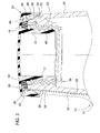
- Fig. 2
- is a perspective view of an insert being part of the grounded fuel tank assembly shown in
Fig. 1 , and - Fig. 3
- is a sectional view taken along a center line of a ground strap of the grounded fuel tank assembly shown in
Fig. 1 . - Referring to
Figs. 1 and2 , a groundedfuel tank assembly 10 includes afuel tank 12 which has a non-metallic tank orcontainer 14 and a non-metallichollow filler neck 16 which projects from thecontainer 14. Thefiller neck 16 has an opening 18 which is surrounded by alip 20. The opening 18 is adapted to receive a hollow stem orshank portion 22 of afuel cap 24. An O-ring 19 is mounted around a base portion of theshank portion 22. Theshank portion 22 includesexternal threads 23. Agroove 26 is formed in an outer surface of thefuel tank 14 and thefiller neck 16. The groundedfuel tank assembly 10 also includes aninsert member 30, an O-ring 32 and aground strap 34. Theground strap 34 is received by thegroove 26. Alternatively, a wire (not shown) in a molded channel could also be used, or a conductor could be molded into thefuel tank 12 to complete the grounding system between the metal fuel fill insert a vehicle ground. - Referring now to
Figs. 2 and3 , thefiller neck 16 includesinternal threads 17. Theinsert member 30 is an electrically conductive, hollow, cylindrical member. Theinsert member 30 has a hollow cylindrical inner part orsleeve 36 which is received by thefiller neck 16. Thesleeve 36 includesexternal threads 38 which engage theinternal threads 17 of thefiller neck 16. Thesleeve 36 also includesinternal threads 40 which engage theexternal threads 23 of theshank portion 22 of thefuel cap 24. - The
insert member 30 also has a ring-shapedouter part 42. Theouter part 42 is joined to an end of thesleeve 36. Theouter part 42 includes an annular frusto-conicalinner ring 44 which is joined to an end of thesleeve 36 and which extends axially away and radially outwardly fromsleeve 36 to a curvedouter rim 46. Theouter part 42 also includes anouter ring 48 which extends axially away from theouter rim 46 and towards thesleeve 36. Theouter part 42 thereby forms anannular recess 50 which opens away from theouter rim 46 and towards thelip 20 of thefiller neck 16. - As best seen in
Fig. 3 , theouter part 42 receives thelip 20 of thefiller neck 16 and the O-ring 32. Thus, the O-ring 32 forms a seal between thelip 20 and theinner ring 44 ofouter part 42. The O-ring 19 forms a seal between thefuel cap 24 and theinner ring 44 ofinsert member 30. Theouter part 42 also receives an end of theground strap 34 so that theground strap 34 makes electrical contact with theouter ring 48. A plurality of spaced aparttabs 56 project away from an outer edge of theouter ring 48. - As best seen in
Figs. 2 and3 , an upper portion of thefiller neck 16 is surrounded by a plurality of evenly spacedfingers 52 which are separated by a corresponding plurality of upwardlyopening slots 54. Eachtab 56 can be bent into a corresponding one of theslots 54 to prevent theinsert member 30 from being rotated and unscrewed from thefiller neck 16. - Thus, the fuel
tank ground assembly 10 includes aninsert member 30 which hasexternal threads 38 for securing it to the moldedplastic fuel tank 12,internal threads 40 for securing thefuel cap 24, andtabs 56 which engage thefiller neck 16 to prevent unscrewing of theinsert member 30. - As the
insert member 30 is screwed into thefiller neck 16, a constant force pushes thegrounding strap 34 inwardly towards thefiller neck 16. The moldedgroove 26 locates theground strap 34 in a defined position and to resist strap rotation while installing theinsert member 30. Thegroove 26 has room for arobust ground strap 34 that is less susceptible to damage and entanglement than a grounding wire. The result is a groundedfuel tank assembly 10 which is simple to put together.
Claims (11)
- A grounded fuel tank assembly comprising a fuel tank (12) having a non-metallic container (14) and a non-metallic filler neck (16), the filler neck (16) having an opening (18) surrounded by a lip (20), the opening (18) being adapted to receive a shank portion (22) of a fuel cap (24); an electrically conductive insert member (30), the insert member (30) having a sleeve (36) which is received by the filler neck (16) and a ring-shaped outer part (42) which at least partially surrounds a portion of the filler neck (16); and an electrically conductive ground strap (34) exterior to the container (14), the ground strap (34) engaging the outer part (42).
- The grounded fuel tank assembly according to claim 1, characterized in that the outer part (42) forms an annular recess (50) which receives the lip (20), and the ground strap (34) has an end which engages the insert member (30) and which is received by the annular recess (50).
- The grounded fuel tank assembly according to claim 1, characterized in that a portion of the filler neck (16) is surrounded by a plurality of evenly spaced fingers (52) which are separated by a corresponding plurality of upwardly opening slots (54), and the insert member (30) includes a plurality of tabs (56) which project away from an outer edge of the outer part (42), each tab (56) being bendable into a corresponding one of the slots (54) to hold the insert member (30) onto the filler neck (16).
- The grounded fuel tank assembly according to claim 1, characterized in that the insert member (30) comprises a hollow cylindrical sleeve (36) which is received by the filler neck (16), an annular frusto-conical inner ring (44) which is joined to an end of the sleeve (36), and an outer ring (48) which extends away from the inner ring (44) and which at least partially surrounds a portion of the filler neck (16).
- The grounded fuel tank assembly according to claim 1, characterized in that the insert member (30) comprises a hollow cylindrical sleeve (36) which is received by the filler neck (16), the sleeve (36) having external threads (38) formed thereon, and the filler neck (16) having internal threads (17) which engage the external threads (38) formed on the sleeve (36).
- The grounded fuel tank assembly according to claim 1, characterized in that the fuel cap (24) includes a hollow shank portion (22), the shank portion (22) having external threads (23) formed thereon, and the insert member (30) comprises a hollow cylindrical sleeve (36) which is received by the filler neck (30), the sleeve (36) having internal threads (40) formed thereon, said internal threads (40) engaging the external threads (23) of the shank portion (22).
- The grounded fuel tank assembly according to claim 1, characterized in that a portion of the ground strap (34) is held between an outer surface of the filler neck (16) and the outer part (42).
- The grounded fuel tank assembly according to claim 1, characterized in that an O-ring (32) sealingly engages the lip (20) and the insert member (30).
- The grounded fuel tank assembly according to claim 8, characterized in that a further O-ring (19) sealingly engages the fuel cap (24) and the insert member (30).
- The grounded fuel tank assembly according to claim 2, characterized in that an O-ring (32) is received by the annular recess (50) and sealingly engages the lip (20) and the insert member (30).
- The grounded fuel tank assembly according to claim 1, characterized in that the ground strap (34) extends along an outer surface of the container (14) and along an outer surface of the filler neck (16).
Applications Claiming Priority (1)
| Application Number | Priority Date | Filing Date | Title |
|---|---|---|---|
| US14/315,428 US9751398B2 (en) | 2014-06-26 | 2014-06-26 | Fuel tank ground assembly |
Publications (2)
| Publication Number | Publication Date |
|---|---|
| EP2960093A1 true EP2960093A1 (en) | 2015-12-30 |
| EP2960093B1 EP2960093B1 (en) | 2017-08-02 |
Family
ID=53510597
Family Applications (1)
| Application Number | Title | Priority Date | Filing Date |
|---|---|---|---|
| EP15172099.2A Active EP2960093B1 (en) | 2014-06-26 | 2015-06-15 | Grounded fuel tank assembly |
Country Status (2)
| Country | Link |
|---|---|
| US (1) | US9751398B2 (en) |
| EP (1) | EP2960093B1 (en) |
Families Citing this family (4)
| Publication number | Priority date | Publication date | Assignee | Title |
|---|---|---|---|---|
| JP6219027B2 (en) * | 2012-10-29 | 2017-10-25 | 八千代工業株式会社 | Filler pipe mounting structure |
| EP3936361B1 (en) * | 2020-07-09 | 2023-04-26 | Magna Energy Storage Systems GesmbH | Fuel tank device |
| CN116723952B (en) * | 2021-02-24 | 2024-04-12 | 八千代工业株式会社 | Grounding structure of filling pipe |
| US12085216B2 (en) * | 2022-02-17 | 2024-09-10 | Arctic Cat Inc. | Multi-use fuel filler tube |
Citations (5)
| Publication number | Priority date | Publication date | Assignee | Title |
|---|---|---|---|---|
| US4540191A (en) | 1984-03-12 | 1985-09-10 | Deere & Company | Static discharge prevention system for a largely non-metallic fuel tank |
| JPH0357724A (en) * | 1989-07-27 | 1991-03-13 | Toyoda Gosei Co Ltd | Pouring inlet of fuel tank |
| FR2774041A1 (en) * | 1998-01-29 | 1999-07-30 | Journee Paul Sa | Vehicle fuel tank plastics orifice fitting with integral electrical earthing to prevent explosions from static electricity |
| DE202005008327U1 (en) * | 2005-05-24 | 2006-10-05 | Gerdes, Monika | Arrangement for upper area of fuel inlet at vehicle, comprises separately produced threaded component |
| DE102012022129A1 (en) * | 2012-11-13 | 2014-05-15 | Kautex Textron Gmbh & Co. Kg | grounding element |
Family Cites Families (3)
| Publication number | Priority date | Publication date | Assignee | Title |
|---|---|---|---|---|
| US5898560A (en) * | 1997-07-17 | 1999-04-27 | Flaynik, Jr.; Donald G. | Static discharge device for electrically non-conductive fluids |
| JP4567438B2 (en) * | 2002-04-23 | 2010-10-20 | マウザー−ヴェルケ ゲゼルシャフト ミット ベシュレンクテル ハフツング | Plastic container |
| US6945290B1 (en) | 2004-06-10 | 2005-09-20 | Eaton Corporation | Check valve for use in filler tube vapor recirculation system and method of making same |
-
2014
- 2014-06-26 US US14/315,428 patent/US9751398B2/en active Active
-
2015
- 2015-06-15 EP EP15172099.2A patent/EP2960093B1/en active Active
Patent Citations (5)
| Publication number | Priority date | Publication date | Assignee | Title |
|---|---|---|---|---|
| US4540191A (en) | 1984-03-12 | 1985-09-10 | Deere & Company | Static discharge prevention system for a largely non-metallic fuel tank |
| JPH0357724A (en) * | 1989-07-27 | 1991-03-13 | Toyoda Gosei Co Ltd | Pouring inlet of fuel tank |
| FR2774041A1 (en) * | 1998-01-29 | 1999-07-30 | Journee Paul Sa | Vehicle fuel tank plastics orifice fitting with integral electrical earthing to prevent explosions from static electricity |
| DE202005008327U1 (en) * | 2005-05-24 | 2006-10-05 | Gerdes, Monika | Arrangement for upper area of fuel inlet at vehicle, comprises separately produced threaded component |
| DE102012022129A1 (en) * | 2012-11-13 | 2014-05-15 | Kautex Textron Gmbh & Co. Kg | grounding element |
Also Published As
| Publication number | Publication date |
|---|---|
| US9751398B2 (en) | 2017-09-05 |
| US20150375615A1 (en) | 2015-12-31 |
| EP2960093B1 (en) | 2017-08-02 |
Similar Documents
| Publication | Publication Date | Title |
|---|---|---|
| EP2960093B1 (en) | Grounded fuel tank assembly | |
| US8618416B2 (en) | Water tight outlet cover | |
| EP4336083A3 (en) | Pre-assembled coupling assembly with cap | |
| JP2011131824A (en) | Fuel feeding device | |
| SE425230B (en) | ARRANGEMENTS FOR INSTALLATION OF TANK LIGHTS IN A FUEL TANK | |
| US10351302B2 (en) | Beverage container with handle | |
| CN110137878B (en) | Cable threading device | |
| US6508374B1 (en) | Filler neck closure with static charge dissipater | |
| US9539964B2 (en) | Earthing element | |
| AU2016378896A1 (en) | Shutoff system for a container | |
| US8672178B2 (en) | Hole plug assembly | |
| US20140141646A1 (en) | Coaxial cable connector | |
| US9793627B2 (en) | Ground terminal fitting | |
| US20100200292A1 (en) | Secondary cap | |
| US11498416B2 (en) | Fuel tank comprising a connector piece | |
| EP2493040A1 (en) | Cable gland | |
| DE60004171D1 (en) | DEVICE FOR MOUNTING A PUMP ON A BOTTLE NECK PROVIDED WITH A FASTENING COLLAR | |
| US4540191A (en) | Static discharge prevention system for a largely non-metallic fuel tank | |
| US2760691A (en) | Plastic nozzle mounting and method of assembling same | |
| US9905949B2 (en) | Fluid conduit | |
| US20120103461A1 (en) | Hose coupling element | |
| JP2015182688A (en) | Earth structure for fuel supply device | |
| CN208817444U (en) | A kind of anti-pull-up structure of waterproof of Tri-proof light leading-out terminal | |
| EP3034430A1 (en) | Cap for closing a bottle and the like and corresponding cap cover | |
| CN110137743B (en) | Plug contact device |
Legal Events
| Date | Code | Title | Description |
|---|---|---|---|
| PUAI | Public reference made under article 153(3) epc to a published international application that has entered the european phase |
Free format text: ORIGINAL CODE: 0009012 |
|
| AK | Designated contracting states |
Kind code of ref document: A1 Designated state(s): AL AT BE BG CH CY CZ DE DK EE ES FI FR GB GR HR HU IE IS IT LI LT LU LV MC MK MT NL NO PL PT RO RS SE SI SK SM TR |
|
| AX | Request for extension of the european patent |
Extension state: BA ME |
|
| 17P | Request for examination filed |
Effective date: 20160630 |
|
| RBV | Designated contracting states (corrected) |
Designated state(s): AL AT BE BG CH CY CZ DE DK EE ES FI FR GB GR HR HU IE IS IT LI LT LU LV MC MK MT NL NO PL PT RO RS SE SI SK SM TR |
|
| GRAP | Despatch of communication of intention to grant a patent |
Free format text: ORIGINAL CODE: EPIDOSNIGR1 |
|
| RIC1 | Information provided on ipc code assigned before grant |
Ipc: B60K 15/04 20060101AFI20170127BHEP Ipc: B60K 15/03 20060101ALN20170127BHEP |
|
| INTG | Intention to grant announced |
Effective date: 20170224 |
|
| RIC1 | Information provided on ipc code assigned before grant |
Ipc: B60K 15/03 20060101ALN20170216BHEP Ipc: B60K 15/04 20060101AFI20170216BHEP |
|
| GRAS | Grant fee paid |
Free format text: ORIGINAL CODE: EPIDOSNIGR3 |
|
| GRAA | (expected) grant |
Free format text: ORIGINAL CODE: 0009210 |
|
| AK | Designated contracting states |
Kind code of ref document: B1 Designated state(s): AL AT BE BG CH CY CZ DE DK EE ES FI FR GB GR HR HU IE IS IT LI LT LU LV MC MK MT NL NO PL PT RO RS SE SI SK SM TR |
|
| REG | Reference to a national code |
Ref country code: CH Ref legal event code: EP Ref country code: AT Ref legal event code: REF Ref document number: 914048 Country of ref document: AT Kind code of ref document: T Effective date: 20170815 |
|
| REG | Reference to a national code |
Ref country code: IE Ref legal event code: FG4D |
|
| REG | Reference to a national code |
Ref country code: DE Ref legal event code: R096 Ref document number: 602015003835 Country of ref document: DE |
|
| REG | Reference to a national code |
Ref country code: NL Ref legal event code: MP Effective date: 20170802 |
|
| REG | Reference to a national code |
Ref country code: AT Ref legal event code: MK05 Ref document number: 914048 Country of ref document: AT Kind code of ref document: T Effective date: 20170802 |
|
| REG | Reference to a national code |
Ref country code: LT Ref legal event code: MG4D |
|
| PG25 | Lapsed in a contracting state [announced via postgrant information from national office to epo] |
Ref country code: HR Free format text: LAPSE BECAUSE OF FAILURE TO SUBMIT A TRANSLATION OF THE DESCRIPTION OR TO PAY THE FEE WITHIN THE PRESCRIBED TIME-LIMIT Effective date: 20170802 Ref country code: SE Free format text: LAPSE BECAUSE OF FAILURE TO SUBMIT A TRANSLATION OF THE DESCRIPTION OR TO PAY THE FEE WITHIN THE PRESCRIBED TIME-LIMIT Effective date: 20170802 Ref country code: AT Free format text: LAPSE BECAUSE OF FAILURE TO SUBMIT A TRANSLATION OF THE DESCRIPTION OR TO PAY THE FEE WITHIN THE PRESCRIBED TIME-LIMIT Effective date: 20170802 Ref country code: FI Free format text: LAPSE BECAUSE OF FAILURE TO SUBMIT A TRANSLATION OF THE DESCRIPTION OR TO PAY THE FEE WITHIN THE PRESCRIBED TIME-LIMIT Effective date: 20170802 Ref country code: NL Free format text: LAPSE BECAUSE OF FAILURE TO SUBMIT A TRANSLATION OF THE DESCRIPTION OR TO PAY THE FEE WITHIN THE PRESCRIBED TIME-LIMIT Effective date: 20170802 Ref country code: NO Free format text: LAPSE BECAUSE OF FAILURE TO SUBMIT A TRANSLATION OF THE DESCRIPTION OR TO PAY THE FEE WITHIN THE PRESCRIBED TIME-LIMIT Effective date: 20171102 Ref country code: LT Free format text: LAPSE BECAUSE OF FAILURE TO SUBMIT A TRANSLATION OF THE DESCRIPTION OR TO PAY THE FEE WITHIN THE PRESCRIBED TIME-LIMIT Effective date: 20170802 |
|
| PG25 | Lapsed in a contracting state [announced via postgrant information from national office to epo] |
Ref country code: RS Free format text: LAPSE BECAUSE OF FAILURE TO SUBMIT A TRANSLATION OF THE DESCRIPTION OR TO PAY THE FEE WITHIN THE PRESCRIBED TIME-LIMIT Effective date: 20170802 Ref country code: GR Free format text: LAPSE BECAUSE OF FAILURE TO SUBMIT A TRANSLATION OF THE DESCRIPTION OR TO PAY THE FEE WITHIN THE PRESCRIBED TIME-LIMIT Effective date: 20171103 Ref country code: ES Free format text: LAPSE BECAUSE OF FAILURE TO SUBMIT A TRANSLATION OF THE DESCRIPTION OR TO PAY THE FEE WITHIN THE PRESCRIBED TIME-LIMIT Effective date: 20170802 Ref country code: BG Free format text: LAPSE BECAUSE OF FAILURE TO SUBMIT A TRANSLATION OF THE DESCRIPTION OR TO PAY THE FEE WITHIN THE PRESCRIBED TIME-LIMIT Effective date: 20171102 Ref country code: LV Free format text: LAPSE BECAUSE OF FAILURE TO SUBMIT A TRANSLATION OF THE DESCRIPTION OR TO PAY THE FEE WITHIN THE PRESCRIBED TIME-LIMIT Effective date: 20170802 Ref country code: IS Free format text: LAPSE BECAUSE OF FAILURE TO SUBMIT A TRANSLATION OF THE DESCRIPTION OR TO PAY THE FEE WITHIN THE PRESCRIBED TIME-LIMIT Effective date: 20171202 Ref country code: PL Free format text: LAPSE BECAUSE OF FAILURE TO SUBMIT A TRANSLATION OF THE DESCRIPTION OR TO PAY THE FEE WITHIN THE PRESCRIBED TIME-LIMIT Effective date: 20170802 |
|
| PG25 | Lapsed in a contracting state [announced via postgrant information from national office to epo] |
Ref country code: RO Free format text: LAPSE BECAUSE OF FAILURE TO SUBMIT A TRANSLATION OF THE DESCRIPTION OR TO PAY THE FEE WITHIN THE PRESCRIBED TIME-LIMIT Effective date: 20170802 Ref country code: CZ Free format text: LAPSE BECAUSE OF FAILURE TO SUBMIT A TRANSLATION OF THE DESCRIPTION OR TO PAY THE FEE WITHIN THE PRESCRIBED TIME-LIMIT Effective date: 20170802 Ref country code: DK Free format text: LAPSE BECAUSE OF FAILURE TO SUBMIT A TRANSLATION OF THE DESCRIPTION OR TO PAY THE FEE WITHIN THE PRESCRIBED TIME-LIMIT Effective date: 20170802 |
|
| REG | Reference to a national code |
Ref country code: DE Ref legal event code: R097 Ref document number: 602015003835 Country of ref document: DE |
|
| PG25 | Lapsed in a contracting state [announced via postgrant information from national office to epo] |
Ref country code: IT Free format text: LAPSE BECAUSE OF FAILURE TO SUBMIT A TRANSLATION OF THE DESCRIPTION OR TO PAY THE FEE WITHIN THE PRESCRIBED TIME-LIMIT Effective date: 20170802 Ref country code: EE Free format text: LAPSE BECAUSE OF FAILURE TO SUBMIT A TRANSLATION OF THE DESCRIPTION OR TO PAY THE FEE WITHIN THE PRESCRIBED TIME-LIMIT Effective date: 20170802 Ref country code: SM Free format text: LAPSE BECAUSE OF FAILURE TO SUBMIT A TRANSLATION OF THE DESCRIPTION OR TO PAY THE FEE WITHIN THE PRESCRIBED TIME-LIMIT Effective date: 20170802 Ref country code: SK Free format text: LAPSE BECAUSE OF FAILURE TO SUBMIT A TRANSLATION OF THE DESCRIPTION OR TO PAY THE FEE WITHIN THE PRESCRIBED TIME-LIMIT Effective date: 20170802 |
|
| PLBE | No opposition filed within time limit |
Free format text: ORIGINAL CODE: 0009261 |
|
| STAA | Information on the status of an ep patent application or granted ep patent |
Free format text: STATUS: NO OPPOSITION FILED WITHIN TIME LIMIT |
|
| 26N | No opposition filed |
Effective date: 20180503 |
|
| PG25 | Lapsed in a contracting state [announced via postgrant information from national office to epo] |
Ref country code: SI Free format text: LAPSE BECAUSE OF FAILURE TO SUBMIT A TRANSLATION OF THE DESCRIPTION OR TO PAY THE FEE WITHIN THE PRESCRIBED TIME-LIMIT Effective date: 20170802 |
|
| REG | Reference to a national code |
Ref country code: CH Ref legal event code: PL |
|
| REG | Reference to a national code |
Ref country code: BE Ref legal event code: MM Effective date: 20180630 |
|
| REG | Reference to a national code |
Ref country code: IE Ref legal event code: MM4A |
|
| PG25 | Lapsed in a contracting state [announced via postgrant information from national office to epo] |
Ref country code: LU Free format text: LAPSE BECAUSE OF NON-PAYMENT OF DUE FEES Effective date: 20180615 Ref country code: MC Free format text: LAPSE BECAUSE OF FAILURE TO SUBMIT A TRANSLATION OF THE DESCRIPTION OR TO PAY THE FEE WITHIN THE PRESCRIBED TIME-LIMIT Effective date: 20170802 |
|
| PG25 | Lapsed in a contracting state [announced via postgrant information from national office to epo] |
Ref country code: LI Free format text: LAPSE BECAUSE OF NON-PAYMENT OF DUE FEES Effective date: 20180630 Ref country code: CH Free format text: LAPSE BECAUSE OF NON-PAYMENT OF DUE FEES Effective date: 20180630 Ref country code: IE Free format text: LAPSE BECAUSE OF NON-PAYMENT OF DUE FEES Effective date: 20180615 Ref country code: FR Free format text: LAPSE BECAUSE OF NON-PAYMENT OF DUE FEES Effective date: 20180630 |
|
| PG25 | Lapsed in a contracting state [announced via postgrant information from national office to epo] |
Ref country code: BE Free format text: LAPSE BECAUSE OF NON-PAYMENT OF DUE FEES Effective date: 20180630 |
|
| PG25 | Lapsed in a contracting state [announced via postgrant information from national office to epo] |
Ref country code: MT Free format text: LAPSE BECAUSE OF NON-PAYMENT OF DUE FEES Effective date: 20180615 |
|
| PG25 | Lapsed in a contracting state [announced via postgrant information from national office to epo] |
Ref country code: TR Free format text: LAPSE BECAUSE OF FAILURE TO SUBMIT A TRANSLATION OF THE DESCRIPTION OR TO PAY THE FEE WITHIN THE PRESCRIBED TIME-LIMIT Effective date: 20170802 |
|
| PG25 | Lapsed in a contracting state [announced via postgrant information from national office to epo] |
Ref country code: PT Free format text: LAPSE BECAUSE OF FAILURE TO SUBMIT A TRANSLATION OF THE DESCRIPTION OR TO PAY THE FEE WITHIN THE PRESCRIBED TIME-LIMIT Effective date: 20170802 |
|
| PG25 | Lapsed in a contracting state [announced via postgrant information from national office to epo] |
Ref country code: MK Free format text: LAPSE BECAUSE OF NON-PAYMENT OF DUE FEES Effective date: 20170802 Ref country code: HU Free format text: LAPSE BECAUSE OF FAILURE TO SUBMIT A TRANSLATION OF THE DESCRIPTION OR TO PAY THE FEE WITHIN THE PRESCRIBED TIME-LIMIT; INVALID AB INITIO Effective date: 20150615 Ref country code: CY Free format text: LAPSE BECAUSE OF FAILURE TO SUBMIT A TRANSLATION OF THE DESCRIPTION OR TO PAY THE FEE WITHIN THE PRESCRIBED TIME-LIMIT Effective date: 20170802 |
|
| PG25 | Lapsed in a contracting state [announced via postgrant information from national office to epo] |
Ref country code: AL Free format text: LAPSE BECAUSE OF FAILURE TO SUBMIT A TRANSLATION OF THE DESCRIPTION OR TO PAY THE FEE WITHIN THE PRESCRIBED TIME-LIMIT Effective date: 20170802 |
|
| PGFP | Annual fee paid to national office [announced via postgrant information from national office to epo] |
Ref country code: DE Payment date: 20250521 Year of fee payment: 11 |
|
| PGFP | Annual fee paid to national office [announced via postgrant information from national office to epo] |
Ref country code: GB Payment date: 20250627 Year of fee payment: 11 |