EP2960082A2 - Tire inflation system having a seal - Google Patents
Tire inflation system having a seal Download PDFInfo
- Publication number
- EP2960082A2 EP2960082A2 EP15164334.3A EP15164334A EP2960082A2 EP 2960082 A2 EP2960082 A2 EP 2960082A2 EP 15164334 A EP15164334 A EP 15164334A EP 2960082 A2 EP2960082 A2 EP 2960082A2
- Authority
- EP
- European Patent Office
- Prior art keywords
- seal
- spindle
- annular
- lip portion
- pressurized gas
- Prior art date
- Legal status (The legal status is an assumption and is not a legal conclusion. Google has not performed a legal analysis and makes no representation as to the accuracy of the status listed.)
- Granted
Links
Images


Classifications
-
- B—PERFORMING OPERATIONS; TRANSPORTING
- B60—VEHICLES IN GENERAL
- B60C—VEHICLE TYRES; TYRE INFLATION; TYRE CHANGING; CONNECTING VALVES TO INFLATABLE ELASTIC BODIES IN GENERAL; DEVICES OR ARRANGEMENTS RELATED TO TYRES
- B60C19/00—Tyre parts or constructions not otherwise provided for
-
- B—PERFORMING OPERATIONS; TRANSPORTING
- B60—VEHICLES IN GENERAL
- B60C—VEHICLE TYRES; TYRE INFLATION; TYRE CHANGING; CONNECTING VALVES TO INFLATABLE ELASTIC BODIES IN GENERAL; DEVICES OR ARRANGEMENTS RELATED TO TYRES
- B60C23/00—Devices for measuring, signalling, controlling, or distributing tyre pressure or temperature, specially adapted for mounting on vehicles; Arrangement of tyre inflating devices on vehicles, e.g. of pumps or of tanks; Tyre cooling arrangements
- B60C23/001—Devices for manually or automatically controlling or distributing tyre pressure whilst the vehicle is moving
- B60C23/003—Devices for manually or automatically controlling or distributing tyre pressure whilst the vehicle is moving comprising rotational joints between vehicle-mounted pressure sources and the tyres
- B60C23/00309—Devices for manually or automatically controlling or distributing tyre pressure whilst the vehicle is moving comprising rotational joints between vehicle-mounted pressure sources and the tyres characterised by the location of the components, e.g. valves, sealings, conduits or sensors
- B60C23/00318—Devices for manually or automatically controlling or distributing tyre pressure whilst the vehicle is moving comprising rotational joints between vehicle-mounted pressure sources and the tyres characterised by the location of the components, e.g. valves, sealings, conduits or sensors on the wheels or the hubs
-
- B—PERFORMING OPERATIONS; TRANSPORTING
- B60—VEHICLES IN GENERAL
- B60C—VEHICLE TYRES; TYRE INFLATION; TYRE CHANGING; CONNECTING VALVES TO INFLATABLE ELASTIC BODIES IN GENERAL; DEVICES OR ARRANGEMENTS RELATED TO TYRES
- B60C23/00—Devices for measuring, signalling, controlling, or distributing tyre pressure or temperature, specially adapted for mounting on vehicles; Arrangement of tyre inflating devices on vehicles, e.g. of pumps or of tanks; Tyre cooling arrangements
- B60C23/001—Devices for manually or automatically controlling or distributing tyre pressure whilst the vehicle is moving
- B60C23/003—Devices for manually or automatically controlling or distributing tyre pressure whilst the vehicle is moving comprising rotational joints between vehicle-mounted pressure sources and the tyres
- B60C23/00345—Details of the rotational joints
-
- B—PERFORMING OPERATIONS; TRANSPORTING
- B60—VEHICLES IN GENERAL
- B60C—VEHICLE TYRES; TYRE INFLATION; TYRE CHANGING; CONNECTING VALVES TO INFLATABLE ELASTIC BODIES IN GENERAL; DEVICES OR ARRANGEMENTS RELATED TO TYRES
- B60C23/00—Devices for measuring, signalling, controlling, or distributing tyre pressure or temperature, specially adapted for mounting on vehicles; Arrangement of tyre inflating devices on vehicles, e.g. of pumps or of tanks; Tyre cooling arrangements
- B60C23/001—Devices for manually or automatically controlling or distributing tyre pressure whilst the vehicle is moving
- B60C23/003—Devices for manually or automatically controlling or distributing tyre pressure whilst the vehicle is moving comprising rotational joints between vehicle-mounted pressure sources and the tyres
- B60C23/00363—Details of sealings
-
- F—MECHANICAL ENGINEERING; LIGHTING; HEATING; WEAPONS; BLASTING
- F16—ENGINEERING ELEMENTS AND UNITS; GENERAL MEASURES FOR PRODUCING AND MAINTAINING EFFECTIVE FUNCTIONING OF MACHINES OR INSTALLATIONS; THERMAL INSULATION IN GENERAL
- F16J—PISTONS; CYLINDERS; SEALINGS
- F16J15/00—Sealings
- F16J15/16—Sealings between relatively-moving surfaces
- F16J15/32—Sealings between relatively-moving surfaces with elastic sealings, e.g. O-rings
- F16J15/3268—Mounting of sealing rings
Definitions
- This patent application relates to a tire inflation system that may have a seal.
- a tire inflation system may include a pressurized gas source and a first seal.
- the pressurized gas source may provide a pressurized gas for inflating a tire.
- the first seal may at least partially define a connection passage that may fluidly connect the pressurized gas source to the tire.
- the first seal may have an annular mounting portion and an annular lip portion that may extend from the annular mounting portion.
- the annular lip portion may have a sealing side and a non-sealing side disposed opposite the sealing side.
- the first seal may inhibit leakage of the pressurized gas when the sealing side faces away from the annular mounting portion.
- the first seal may enable leakage of the pressurized gas when the annular lip portion is rolled such that at least a portion of the sealing side faces toward the annular mounting portion.
- a tire inflation system may include a spindle, a hub, and a first seal.
- the spindle may at least partially define a spindle passage for routing a pressurized gas.
- the hub may be disposed proximate the spindle may at least partially define a hub passage for routing the pressurized gas.
- the first seal may be disposed between the spindle and the hub and may be configured to at least partially define a connection passage that fluidly connects the spindle passage and the hub passage.
- the first seal may have an annular mounting portion and an annular lip portion. The annular mounting portion may extend around the spindle and may be disposed proximate the hub.
- the annular lip portion may extend from the annular mounting portion and may have a sealing side and a non-sealing side disposed opposite the sealing side. Leakage of pressurized gas between the first seal and the spindle may be inhibited when the sealing side engages the spindle. Leakage of pressurized gas between the first seal and the spindle may be enabled when the annular lip portion is rolled such that at least a portion of the sealing side faces toward the spindle.
- the axle assembly 10 may be provided with a motor vehicle like a truck, bus, farm equipment, military transport or weaponry vehicle, or cargo loading equipment for land, air, or marine vessels, or a trailer that may be provided with a motor vehicle.
- a motor vehicle like a truck, bus, farm equipment, military transport or weaponry vehicle, or cargo loading equipment for land, air, or marine vessels, or a trailer that may be provided with a motor vehicle.
- the axle assembly 10 may facilitate mounting of one or more wheels to the vehicle and may or may not be steerable.
- the axle assembly 10 may be configured as a drive axle or a non-drive axle.
- the axle assembly 10 may receive torque from a power source, such as an internal combustion engine or an electric motor that may be used to propel the vehicle.
- a power source such as an internal combustion engine or an electric motor that may be used to propel the vehicle.
- the axle assembly 10 may not receive torque from a power source.
- the axle assembly 10 is shown with a drive axle configuration that may include an axle housing 20, an axle shaft 22, a spindle 24, and a wheel end assembly 26.
- the axle housing 20 may receive various components of the axle assembly 10. In addition, the axle housing 20 may facilitate mounting of the axle assembly 10 to the vehicle.
- the axle housing 20 may define a cavity that may receive at least a portion of the axle shaft 22.
- the axle shaft 22 may provide torque to the wheel end assembly 26 to propel the vehicle.
- the axle shaft 22 may be connected at a first end to a vehicle drivetrain component, like a differential or input shaft, and may be coupled to the wheel end assembly 26 at a second end.
- the axle shaft 22 may extend along and may rotate about an axis 30.
- the axle shaft 22 may be configured for use with an independent suspension system and may have multiple shaft segments and/or joints, such as constant-velocity joints, which may facilitate relative movement between the first end and the wheel end assembly 26.
- the axle shaft 22 may include an axle flange 32 disposed at an end of the axle shaft 22. The axle flange 32 may facilitate mounting of the wheel end assembly 26 to the axle shaft 22. In a non-drive axle configuration, the axle shaft 22 may be omitted.
- the spindle 24 may be provided with or may be fixedly positioned with respect to the axle assembly 10.
- the spindle 24 may generally extend along but may not rotate about the axis 30.
- the spindle 24 may include a first spindle end surface 40, a second spindle end surface 42, an internal surface 44, an external surface 46, and a hole 48.
- the internal surface 44 and the hole 48 may be omitted.
- the spindle 24 may be provided with or may be fixedly positioned with respect to a steering knuckle rather than the axle housing 20.
- the first spindle end surface 40 may be disposed proximate or may engage the axle housing 20. Alternatively, the first spindle end surface 40 may be omitted in a configuration in which the spindle 24 is integrally formed with the axle housing 20 or is not provided as a separate component.
- the second spindle end surface 42 may be disposed opposite the first spindle end surface 40.
- the second spindle end surface 42 may be located near the axle flange 32.
- the internal surface 44 may extend between the first spindle end surface 40 and the second spindle end surface 42 and may at least partially define the hole 48 through which the axle shaft 22 may extend.
- the spindle 24 may be spaced apart from the axle shaft 22 to permit the axle shaft 22 to rotate about the axis 30.
- the hole 48 may receive a conduit, such as a hose, tubing or the like that may route pressurized gas for inflating a tire.
- the external surface 46 may be disposed opposite the internal surface 44.
- the external surface 46 of the spindle 24 may support one or more wheel bearings that may rotatably support the wheel end assembly 26 as will be discussed in more detail below.
- the wheel end assembly 26 may be rotatably disposed on the spindle 24. In a drive axle configuration, the wheel end assembly 26 may be coupled to the axle shaft 22. In at least one embodiment, the wheel end assembly 26 may include a hub 50, a wheel end seal assembly 52, a brake subsystem 54, a wheel 56, and a tire 58.
- the hub 50 may be rotatably disposed on the spindle 24.
- one or more wheel bearings may be mounted on spindle 24 and may rotatably support the hub 50.
- a first wheel bearing 60 and a second wheel bearing 62 are provided in a cavity 64 that is located between the spindle 24 and the hub 50.
- the first wheel bearing 60 may be disposed inboard or further from the second spindle end surface 42 than the second wheel bearing 62.
- the hub 50 may be configured to rotate about the axis 30 with respect to the spindle 24.
- the axle flange 32 may be coupled to the hub 50 with one or more fasteners 66 such as bolts.
- the hub 50 may rotate with the axle shaft 22.
- the hub 50 may not be coupled to an axle shaft 22 or axle flange 32.
- the wheel end seal assembly 52 may be disposed between the spindle 24 and the hub 50.
- the wheel end seal assembly 52 may inhibit contaminants from entering the cavity 64 and may help retain lubricant in the cavity 64.
- the wheel end seal assembly 52 may be fixedly disposed with respect to the hub 50 and may rotate about the axis 30 and with respect to the spindle 24.
- the wheel end seal assembly 52 may be fixedly disposed with respect to the spindle 24 and the hub 50 may rotate about the axis 30 and with respect to the wheel end seal assembly 52.
- Various configurations of the wheel end seal assembly 52 will be discussed in more detail below.
- the brake subsystem 54 may be adapted to slow or inhibit rotation of at least one associated wheel 56.
- the brake subsystem 54 may be configured as a friction brake, such as a drum brake or a disc brake.
- a portion of the brake subsystem 54 is shown with a drum brake configuration.
- a brake drum 70 may be fixedly disposed on the hub 50 with one or more fasteners 72, such as wheel lug studs.
- the brake drum 70 may extend continuously around brake shoe assemblies (not shown) that may be configured to engage the brake drum 70 to slow rotation of an associated wheel 56.
- the wheel 56 which may also be called a wheel rim, may be configured to support and facilitate mounting of an associated tire 58.
- the tire 58 may be a pneumatic tire that may be inflated with a pressurized gas or pressurized gas mixture.
- the wheel 56 may be fixedly positioned with respect to the hub 50.
- the wheel 56 may have a wheel mounting flange 74 that may have a set of holes that may each receive a fastener 72 that may help mount on the wheel 56 to the hub 50.
- a lug nut 76 may be threaded onto each fastener 72 to secure the wheel 56 to the hub 50.
- the lug nut 76 may engage or may be disposed proximate an outboard side 78 of the wheel mounting flange 74 that may face away from the brake drum 70 or toward the axle flange 32.
- a tire inflation system 80 may be associated with the wheel end assembly 26.
- the tire inflation system 80 may be disposed on the vehicle and may be configured to provide a pressurized gas or pressurized gas mixture to one or more tires 58.
- pressurized gas may refer to either a pressurized gas or a pressurized gas mixture in this application.
- the tire inflation system 80 may include a control system that may monitor and control the inflation of one or more tires 58, a pressurized gas source 82, and a gas supply subsystem 84.
- the pressurized gas source 82 may be configured to supply or store a volume of a pressurized gas or pressurized gas mixture, like air or nitrogen.
- the pressurized gas source 82 may be a tank and/or a pump like a compressor.
- the pressurized gas source 82 may be disposed on the vehicle and may provide a pressurized gas or pressurized gas mixture at a pressure that is greater than or equal to a desired inflation pressure of a tire 58. As such, the pressurized gas source 82 may inflate a tire or maintain a desired tire pressure.
- the gas supply subsystem 84 may fluidly connect the pressurized gas source 82 to the tire 58.
- the gas supply subsystem 84 may include one or more conduits, such as a hose, tubing, pipe, or combinations thereof.
- one or more valves may be associated with or provided with a conduit to enable or disable the flow of the pressurized gas from the pressurized gas source 82 to one or more tires 58.
- the gas supply subsystem 84 includes a first conduit 90 and a second conduit 92.
- the first conduit 90 may supply pressurized gas from the pressurized gas source 82 to the axle assembly 10 or may fluidly connect the pressurized gas source 82 to the axle assembly 10.
- the second conduit 92 may supply pressurized gas from the axle assembly 10 to a tire 58 or may fluidly connect the pressurized gas source 82 to the tire 58.
- the routing of the conduits between the pressurized gas source 82 and a tire 58 is exemplary and is not meant to be limiting as other conduit routing paths may be provided.
- pressurized gas may be routed through a passage in the hub 50 or through a hollow fastener that may extend through the hub 50.
- the flow of pressurized gas is represented by the arrows near the conduits in Figure 1 .
- the gas supply subsystem 84 may be provided in various configurations. In the embodiment shown in Figure 1 , the gas supply subsystem 84 routes pressurized gas from the pressurized gas source 82 through a spindle passage 96 and a hub passage 98.
- the spindle passage 96 may be provided in or at least partially defined by the spindle 24.
- the spindle passage 96 may be a hole that may be completely defined in the spindle 24 or may be partially defined by the spindle 24 and another component, such as a sleeve that may extend around a portion of the spindle 24 and which may be at least partially spaced apart from the spindle to form the spindle passage 96.
- the spindle passage 96 may or may not extend to the hole 48 in the spindle 24.
- the spindle passage 96 may be spaced apart from the hole 48 as shown or alternatively may extend to the hole 48.
- the spindle passage 96 may be provided in another component that may be disposed between the spindle 24 and the hub 50.
- a conduit, such as the first conduit 90, may be fluidly connected to an inlet of the spindle passage 96.
- the hub passage 98 may be provided in or may be at least partially defined by the hub 50.
- the hub passage 98 may be completely defined in the hub 50 or may be partially defined by the spindle 24 and another component.
- a conduit, such as the second conduit 92, may be fluidly connected to an outlet of the hub passage 98.
- the wheel end seal assembly 52 may be configured to fluidly connect the first conduit 90 to the second conduit 92.
- the wheel end seal assembly 52 may fluidly connect the spindle passage 96 to the hub passage 98 and the second conduit 92.
- a first embodiment of a wheel end seal assembly 52 may include a mounting ring 100, a first seal 102, and a second seal 104.
- the mounting ring 100 may facilitate mounting of the first seal 102 and/or the second seal 104.
- the first seal 102 and the second seal 104 may be disposed proximate and may be fixedly mounted to the mounting ring 100.
- the first seal 102 and the second seal 104 may be mounted on separate mounting rings in one or more embodiments.
- the mounting ring 100 may include an opening 106 that may allow pressurized gas to pass through the mounting ring 100 and enter the hub passage 98.
- the opening 106 may be disposed between the first seal 102 and the second seal 104 in one or more embodiments.
- the mounting ring 100 may be mounted to or fixedly positioned with respect to the hub 50. As such, the mounting ring 100, first seal 102, and second seal 104 may rotate with the hub 50 about the axis 30 and with respect to the spindle 24.
- the first seal 102 and the second seal 104 may be at least partially spaced apart from each other.
- the first seal 102 and the second seal 104 may cooperate to at least partially define a connection passage 108 that may fluidly connect the pressurized gas source 82 to the tire 58.
- the connection passage 108 may be disposed between the first seal 102 and the second seal 104.
- the connection passage 108 may receive pressurized gas from the outlet of the spindle passage 96 and may route or provide pressurized gas to an inlet of the hub passage 98.
- the first seal 102 may be disposed between the second seal 104 and the second spindle end surface 42 and/or first wheel bearing 60 from the perspective shown.
- the first seal 102 and the second seal 104 may have substantially similar configurations. Referring to Figure 3 , an example of such a seal configuration is shown. In the discussion below, the seal may be referred to as the first seal 102, but it is to be understood that the same attributes may apply to the second seal 104. As such, the term “seal” may refer to the first seal 102 and/or the second seal 104.
- the first seal 102 may include an annular mounting portion 110 and an annular lip portion 112.
- the annular mounting portion 110 may be disposed between the spindle 24 and the hub 50.
- the annular mounting portion 110 may extend around the axis 30.
- the annular mounting portion 110 may be configured as a continuous ring that may extend around the spindle 24.
- the annular mounting portion 110 may be disposed proximate the hub 50.
- the annular lip portion 112 may extend from the annular mounting portion 110.
- the annular lip portion 112 may have a sealing side 120 and a non-sealing side 122.
- the sealing side 120 may be configured to sealingly engage the spindle 24 to inhibit the leakage of pressurized gas between the seal and the spindle 24.
- the sealing side 120 may face away from the annular mounting portion 110 and may extend around and may continuously engage the spindle 24 when the seal is properly installed. At least a portion of the sealing side 120 may face toward the annular mounting portion 110 when the annular lip portion 112 is rolled or when the seal is not properly installed as will be discussed in more detail below.
- the sealing side 120 may be substantially smooth and may form an inner circumferential surface of the seal.
- the non-sealing side 122 may be disposed opposite the sealing side 120.
- the non-sealing side 122 may face toward the annular mounting portion 110 when the seal is properly installed. At least a portion of the non-sealing side 122 may face away from the annular mounting portion 110 when the annular lip portion 112 is rolled or when the seal is not properly installed as will be discussed in more detail below.
- the non-sealing side 122 may include a set of protrusions 130.
- the protrusions 130 may be disposed on the non-sealing side 122 such that the protrusions 130 extend away from the sealing side 120 and toward the annular mounting portion 110.
- the members of the set of protrusions 130 may be spaced apart from each other. As such, adjacent members of the set of protrusions 130 may cooperate to define a gap 132 that may be disposed between adjacent protrusions 130.
- the gap 132 may extend from a distal end 134 of the annular lip portion 112 to or toward the annular mounting portion 110.
- the gap 132 may allow pressurized gas to leak between the seal and the spindle 24 when the annular lip portion 112 is rolled or when the seal is not properly installed such that the leakage may be readily detectable by a pressure test or leak test.
- a pressure test or leak test may allow and a rolled or improperly installed seal to be detected and fixed prior to sale or use.
- the protrusions 130 may be provided with sufficient length and height to provide gaps 132 that allow a readily detectable amount of pressurized gas to leak through one or more gaps 132 when the annular lip portion 112 is rolled.
- the protrusions 130 are configured as ribs that may be radially disposed about the axis 30 and may extend substantially parallel to the axis 30.
- the protrusions 130 may extend from the distal end 134 of the annular lip portion 112 to or toward the annular mounting portion 110.
- Each protrusion 130 may include a protrusion tip surface 136 that may be disposed opposite the sealing side 120 of the annular lip portion 112.
- At least a portion of the protrusion tip surface 136 may face away from the spindle 24 when in sealing side 120 engages the spindle 24. At least a portion of the protrusion tip surface 136 may face toward and may engage the spindle 24 when the annular lip portion 112 is rolled as is best shown in Figure 2A .
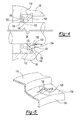
- the annular lip portion 112 may include a first annular segment 140 and a second annular segment 142 as is best shown in Figure 4 .
- the first annular segment 140 may extend from the annular mounting portion 110 toward the spindle 24.
- first annular segment 140 may generally extend at an angle from the annular mounting portion 110 to the second annular segment 142 and may be completely spaced apart from the spindle 24.
- the protrusions 130 may extend along at least a portion of the first annular segment 140 such that the first annular segment 140 may be at least partially spaced apart from the spindle 24 when the annular lip portion 112 is rolled to permit pressurized gas leakage through one or more gaps 132.
- the gaps 132 may be wider than the protrusions 130 as is best shown in Figure 2A to help insure that leakage is readily detectible during a leak test when the annular lip portion 112 is rolled.
- the second annular segment 142 may extend from an end of the first annular segment 140 that is disposed opposite the annular mounting portion 110 to the distal end 134.
- the second annular segment 142 may be disposed opposite and may be spaced apart from the annular mounting portion 110 when the annular lip portion 112 is not rolled.
- the sealing side 120 may be completely disposed on the second annular segment 142.
- the protrusions 130 may extend away from the sealing side 120 and may extend across or along the entire axial length of the second annular segment 142.
- first seal 102 and the second seal 104 are shown in a properly installed position in solid lines.
- the sealing side 120 of the first seal 102 and the sealing side 120 of the second seal 104 may engage the spindle 24 to inhibit leakage of the pressurized gas.
- the annular lip portion 112 of the first seal 102 and the annular lip portion 112 of the second seal 104 may both extend toward each other and toward the spindle passage 96 when the sealing sides 120 face toward the spindle 24.
- the first seal 102 and the second seal 104 are also shown in an improperly installed position in phantom in Figure 2 .
- the second seal 104 is shown in the improperly installed position in Figure 2A .
- the phantom lines in Figure 2 show exemplary rolled positions in which the annular lip portion 112 of the first seal 102 and the annular lip portion 112 of the second seal 104 are at least partially rolled.
- the annular lip portion 112 of the first seal 102 may not extend toward the connection passage 108 and may extend away from the second seal 104 and its annular lip portion 112 when the annular lip portion 112 of the first seal 102 is rolled.
- One or more protrusions 130 may engage the spindle 24 when the annular lip portion 112 is rolled.
- the non-sealing side 122 may face toward the spindle 24 and pressurized gas may pass through one or more gaps 132 between the protrusions 130 and the spindle 24. Accordingly, the protrusions 130 may enable the leakage of pressurized gas through the gaps 132 when the protrusions 130 face toward and/or engage the spindle 24.
- Figure 4 a seal is shown that is partially rolled. More specifically, a portion of the annular lip portion 112 disposed near the top of Figure 4 is not rolled while a portion of the annular lip portion 112 disposed proximate the bottom of Figure 4 is rolled.
- Figure 4 shows an embodiment of a seal that may be provided without a mounting ring.
- the seal may be received in a recess in the hub 50 and may be positioned such that the annular mounting portion 110 and a portion of the first annular segment 140 may be disposed proximate or may engage the hub 50 while the annular lip portion 112 may engage the spindle 24.
- FIG. 5 another embodiment of a seal is shown.
- This embodiment may be substantially similar to the embodiment shown in Figure 4 except for the configuration of the protrusions.
- the protrusions 130' are configured as substantially smooth bumps that may have a continuously curved outer surface 150 that may engage the spindle 24 when the annular lip portion 112 is rolled or the seal is not properly installed.
- the protrusion 130' is shown partially fragmented to better illustrate the protrusion curvature, but it is to be understood that the fragmented opening would not be provided with the seal.
- the protrusions 130 may be disposed proximate and may be spaced apart from the distal end 134 of the annular lip portion 112 in one or more embodiments.
Abstract
Description
- This patent application relates to a tire inflation system that may have a seal.
- A tire inflation system with an integral wheel seal is disclosed in
U.S. Patent No. 7,931,061 . - In at least one embodiment, a tire inflation system is provided. The tire inflation system may include a pressurized gas source and a first seal. The pressurized gas source may provide a pressurized gas for inflating a tire. The first seal may at least partially define a connection passage that may fluidly connect the pressurized gas source to the tire. The first seal may have an annular mounting portion and an annular lip portion that may extend from the annular mounting portion. The annular lip portion may have a sealing side and a non-sealing side disposed opposite the sealing side. The first seal may inhibit leakage of the pressurized gas when the sealing side faces away from the annular mounting portion. The first seal may enable leakage of the pressurized gas when the annular lip portion is rolled such that at least a portion of the sealing side faces toward the annular mounting portion.
- In at least one embodiment, a tire inflation system is provided. The tire inflation system may include a spindle, a hub, and a first seal. The spindle may at least partially define a spindle passage for routing a pressurized gas. The hub may be disposed proximate the spindle may at least partially define a hub passage for routing the pressurized gas. The first seal may be disposed between the spindle and the hub and may be configured to at least partially define a connection passage that fluidly connects the spindle passage and the hub passage. The first seal may have an annular mounting portion and an annular lip portion. The annular mounting portion may extend around the spindle and may be disposed proximate the hub. The annular lip portion may extend from the annular mounting portion and may have a sealing side and a non-sealing side disposed opposite the sealing side. Leakage of pressurized gas between the first seal and the spindle may be inhibited when the sealing side engages the spindle. Leakage of pressurized gas between the first seal and the spindle may be enabled when the annular lip portion is rolled such that at least a portion of the sealing side faces toward the spindle.
-
-
Figure 1 is a section view of an exemplary wheel end assembly having a tire inflation system. -
Figure 2 is a section view of an embodiment of a wheel end seal assembly. -
Figure 2A is a section view of the wheel end seal assembly alongsection line 2A. -
Figure 3 is a perspective view of a seal that may be provided with a wheel end seal assembly. -
Figure 4 is a section view of another embodiment of a wheel end seal assembly. -
Figure 5 is a fragmentary perspective view of a portion of another seal that may be provided with a wheel end seal assembly. - As required, detailed embodiments of the present invention are disclosed herein; however, it is to be understood that the disclosed embodiments are merely exemplary of the invention that may be embodied in various and alternative forms. The figures are not necessarily to scale; some features may be exaggerated or minimized to show details of particular components. Therefore, specific structural and functional details disclosed herein are not to be interpreted as limiting, but merely as a representative basis for teaching one skilled in the art to variously employ the present invention.
- Referring to
Figure 1 , a portion of anexemplary axle assembly 10 is shown. Theaxle assembly 10 may be provided with a motor vehicle like a truck, bus, farm equipment, military transport or weaponry vehicle, or cargo loading equipment for land, air, or marine vessels, or a trailer that may be provided with a motor vehicle. - The
axle assembly 10 may facilitate mounting of one or more wheels to the vehicle and may or may not be steerable. Theaxle assembly 10 may be configured as a drive axle or a non-drive axle. In a drive axle configuration, theaxle assembly 10 may receive torque from a power source, such as an internal combustion engine or an electric motor that may be used to propel the vehicle. In a non-drive axle configuration, theaxle assembly 10 may not receive torque from a power source. InFigure 1 , theaxle assembly 10 is shown with a drive axle configuration that may include anaxle housing 20, anaxle shaft 22, aspindle 24, and awheel end assembly 26. - The
axle housing 20 may receive various components of theaxle assembly 10. In addition, theaxle housing 20 may facilitate mounting of theaxle assembly 10 to the vehicle. Theaxle housing 20 may define a cavity that may receive at least a portion of theaxle shaft 22. - The
axle shaft 22 may provide torque to thewheel end assembly 26 to propel the vehicle. For instance, theaxle shaft 22 may be connected at a first end to a vehicle drivetrain component, like a differential or input shaft, and may be coupled to thewheel end assembly 26 at a second end. In at least one embodiment, theaxle shaft 22 may extend along and may rotate about anaxis 30. Alternatively, theaxle shaft 22 may be configured for use with an independent suspension system and may have multiple shaft segments and/or joints, such as constant-velocity joints, which may facilitate relative movement between the first end and thewheel end assembly 26. Theaxle shaft 22 may include anaxle flange 32 disposed at an end of theaxle shaft 22. Theaxle flange 32 may facilitate mounting of thewheel end assembly 26 to theaxle shaft 22. In a non-drive axle configuration, theaxle shaft 22 may be omitted. - The
spindle 24 may be provided with or may be fixedly positioned with respect to theaxle assembly 10. Thespindle 24 may generally extend along but may not rotate about theaxis 30. In a drive axle configuration, thespindle 24 may include a firstspindle end surface 40, a secondspindle end surface 42, aninternal surface 44, anexternal surface 46, and ahole 48. In a non-drive axle configuration, theinternal surface 44 and thehole 48 may be omitted. Moreover, in a steerable non-drive axle configuration, thespindle 24 may be provided with or may be fixedly positioned with respect to a steering knuckle rather than theaxle housing 20. - The first
spindle end surface 40 may be disposed proximate or may engage theaxle housing 20. Alternatively, the firstspindle end surface 40 may be omitted in a configuration in which thespindle 24 is integrally formed with theaxle housing 20 or is not provided as a separate component. - The second
spindle end surface 42 may be disposed opposite the firstspindle end surface 40. The secondspindle end surface 42 may be located near theaxle flange 32. - The
internal surface 44 may extend between the firstspindle end surface 40 and the secondspindle end surface 42 and may at least partially define thehole 48 through which theaxle shaft 22 may extend. As such, thespindle 24 may be spaced apart from theaxle shaft 22 to permit theaxle shaft 22 to rotate about theaxis 30. In at least one embodiment, thehole 48 may receive a conduit, such as a hose, tubing or the like that may route pressurized gas for inflating a tire. - The
external surface 46 may be disposed opposite theinternal surface 44. Theexternal surface 46 of thespindle 24 may support one or more wheel bearings that may rotatably support thewheel end assembly 26 as will be discussed in more detail below. - The
wheel end assembly 26 may be rotatably disposed on thespindle 24. In a drive axle configuration, thewheel end assembly 26 may be coupled to theaxle shaft 22. In at least one embodiment, thewheel end assembly 26 may include ahub 50, a wheelend seal assembly 52, abrake subsystem 54, a wheel 56, and atire 58. - The
hub 50 may be rotatably disposed on thespindle 24. For instance, one or more wheel bearings may be mounted onspindle 24 and may rotatably support thehub 50. InFigure 1 , a first wheel bearing 60 and a second wheel bearing 62 are provided in a cavity 64 that is located between thespindle 24 and thehub 50. The first wheel bearing 60 may be disposed inboard or further from the secondspindle end surface 42 than the second wheel bearing 62. As such, thehub 50 may be configured to rotate about theaxis 30 with respect to thespindle 24. In a drive axle configuration, theaxle flange 32 may be coupled to thehub 50 with one or more fasteners 66 such as bolts. As such, thehub 50 may rotate with theaxle shaft 22. In a non-drive axle configuration, thehub 50 may not be coupled to anaxle shaft 22 oraxle flange 32. - The wheel
end seal assembly 52 may be disposed between thespindle 24 and thehub 50. The wheelend seal assembly 52 may inhibit contaminants from entering the cavity 64 and may help retain lubricant in the cavity 64. In at least one embodiment, the wheelend seal assembly 52 may be fixedly disposed with respect to thehub 50 and may rotate about theaxis 30 and with respect to thespindle 24. Alternatively, the wheelend seal assembly 52 may be fixedly disposed with respect to thespindle 24 and thehub 50 may rotate about theaxis 30 and with respect to the wheelend seal assembly 52. Various configurations of the wheelend seal assembly 52 will be discussed in more detail below. - The
brake subsystem 54 may be adapted to slow or inhibit rotation of at least one associated wheel 56. For example, thebrake subsystem 54 may be configured as a friction brake, such as a drum brake or a disc brake. InFigure 1 , a portion of thebrake subsystem 54 is shown with a drum brake configuration. In a drum brake configuration, abrake drum 70 may be fixedly disposed on thehub 50 with one ormore fasteners 72, such as wheel lug studs. Thebrake drum 70 may extend continuously around brake shoe assemblies (not shown) that may be configured to engage thebrake drum 70 to slow rotation of an associated wheel 56. - The wheel 56, which may also be called a wheel rim, may be configured to support and facilitate mounting of an associated
tire 58. Thetire 58 may be a pneumatic tire that may be inflated with a pressurized gas or pressurized gas mixture. The wheel 56 may be fixedly positioned with respect to thehub 50. For example, the wheel 56 may have awheel mounting flange 74 that may have a set of holes that may each receive afastener 72 that may help mount on the wheel 56 to thehub 50. Alug nut 76 may be threaded onto eachfastener 72 to secure the wheel 56 to thehub 50. Thelug nut 76 may engage or may be disposed proximate anoutboard side 78 of thewheel mounting flange 74 that may face away from thebrake drum 70 or toward theaxle flange 32. - A
tire inflation system 80 may be associated with thewheel end assembly 26. Thetire inflation system 80 may be disposed on the vehicle and may be configured to provide a pressurized gas or pressurized gas mixture to one ormore tires 58. For clarity, the term "pressurized gas" may refer to either a pressurized gas or a pressurized gas mixture in this application. Thetire inflation system 80 may include a control system that may monitor and control the inflation of one ormore tires 58, apressurized gas source 82, and agas supply subsystem 84. - The
pressurized gas source 82 may be configured to supply or store a volume of a pressurized gas or pressurized gas mixture, like air or nitrogen. For example, thepressurized gas source 82 may be a tank and/or a pump like a compressor. Thepressurized gas source 82 may be disposed on the vehicle and may provide a pressurized gas or pressurized gas mixture at a pressure that is greater than or equal to a desired inflation pressure of atire 58. As such, thepressurized gas source 82 may inflate a tire or maintain a desired tire pressure. - The
gas supply subsystem 84 may fluidly connect thepressurized gas source 82 to thetire 58. Thegas supply subsystem 84 may include one or more conduits, such as a hose, tubing, pipe, or combinations thereof. In addition, one or more valves may be associated with or provided with a conduit to enable or disable the flow of the pressurized gas from the pressurizedgas source 82 to one ormore tires 58. InFigure 1 , thegas supply subsystem 84 includes afirst conduit 90 and asecond conduit 92. Thefirst conduit 90 may supply pressurized gas from the pressurizedgas source 82 to theaxle assembly 10 or may fluidly connect thepressurized gas source 82 to theaxle assembly 10. Thesecond conduit 92 may supply pressurized gas from theaxle assembly 10 to atire 58 or may fluidly connect thepressurized gas source 82 to thetire 58. The routing of the conduits between thepressurized gas source 82 and atire 58 is exemplary and is not meant to be limiting as other conduit routing paths may be provided. For instance, pressurized gas may be routed through a passage in thehub 50 or through a hollow fastener that may extend through thehub 50. The flow of pressurized gas is represented by the arrows near the conduits inFigure 1 . - The
gas supply subsystem 84 may be provided in various configurations. In the embodiment shown inFigure 1 , thegas supply subsystem 84 routes pressurized gas from the pressurizedgas source 82 through aspindle passage 96 and ahub passage 98. - The
spindle passage 96 may be provided in or at least partially defined by thespindle 24. For instance, thespindle passage 96 may be a hole that may be completely defined in thespindle 24 or may be partially defined by thespindle 24 and another component, such as a sleeve that may extend around a portion of thespindle 24 and which may be at least partially spaced apart from the spindle to form thespindle passage 96. Thespindle passage 96 may or may not extend to thehole 48 in thespindle 24. For instance, thespindle passage 96 may be spaced apart from thehole 48 as shown or alternatively may extend to thehole 48. As another option, thespindle passage 96 may be provided in another component that may be disposed between thespindle 24 and thehub 50. A conduit, such as thefirst conduit 90, may be fluidly connected to an inlet of thespindle passage 96. - The
hub passage 98 may be provided in or may be at least partially defined by thehub 50. For instance, thehub passage 98 may be completely defined in thehub 50 or may be partially defined by thespindle 24 and another component. A conduit, such as thesecond conduit 92, may be fluidly connected to an outlet of thehub passage 98. - Referring to
Figure 2 , an example of a wheelend seal assembly 52 is shown. The wheelend seal assembly 52 may be configured to fluidly connect thefirst conduit 90 to thesecond conduit 92. For example, the wheelend seal assembly 52 may fluidly connect thespindle passage 96 to thehub passage 98 and thesecond conduit 92. - Referring to
Figure 2 , a first embodiment of a wheelend seal assembly 52 is shown that may include a mountingring 100, afirst seal 102, and asecond seal 104. - The mounting
ring 100 may facilitate mounting of thefirst seal 102 and/or thesecond seal 104. For example, thefirst seal 102 and thesecond seal 104 may be disposed proximate and may be fixedly mounted to the mountingring 100. Alternatively, thefirst seal 102 and thesecond seal 104 may be mounted on separate mounting rings in one or more embodiments. The mountingring 100 may include anopening 106 that may allow pressurized gas to pass through the mountingring 100 and enter thehub passage 98. Theopening 106 may be disposed between thefirst seal 102 and thesecond seal 104 in one or more embodiments. In at least one embodiment, the mountingring 100 may be mounted to or fixedly positioned with respect to thehub 50. As such, the mountingring 100,first seal 102, andsecond seal 104 may rotate with thehub 50 about theaxis 30 and with respect to thespindle 24. - The
first seal 102 and thesecond seal 104 may be at least partially spaced apart from each other. Thefirst seal 102 and thesecond seal 104 may cooperate to at least partially define aconnection passage 108 that may fluidly connect thepressurized gas source 82 to thetire 58. Theconnection passage 108 may be disposed between thefirst seal 102 and thesecond seal 104. Theconnection passage 108 may receive pressurized gas from the outlet of thespindle passage 96 and may route or provide pressurized gas to an inlet of thehub passage 98. Thefirst seal 102 may be disposed between thesecond seal 104 and the secondspindle end surface 42 and/or first wheel bearing 60 from the perspective shown. - The
first seal 102 and thesecond seal 104 may have substantially similar configurations. Referring toFigure 3 , an example of such a seal configuration is shown. In the discussion below, the seal may be referred to as thefirst seal 102, but it is to be understood that the same attributes may apply to thesecond seal 104. As such, the term "seal" may refer to thefirst seal 102 and/or thesecond seal 104. Thefirst seal 102 may include anannular mounting portion 110 and anannular lip portion 112. - The
annular mounting portion 110 may be disposed between thespindle 24 and thehub 50. Theannular mounting portion 110 may extend around theaxis 30. As such, the annular mountingportion 110 may be configured as a continuous ring that may extend around thespindle 24. In one or more embodiments, the annular mountingportion 110 may be disposed proximate thehub 50. - The
annular lip portion 112 may extend from the annular mountingportion 110. Theannular lip portion 112 may have a sealingside 120 and anon-sealing side 122. - The sealing
side 120 may be configured to sealingly engage thespindle 24 to inhibit the leakage of pressurized gas between the seal and thespindle 24. As such, the sealingside 120 may face away from the annular mountingportion 110 and may extend around and may continuously engage thespindle 24 when the seal is properly installed. At least a portion of the sealingside 120 may face toward the annular mountingportion 110 when theannular lip portion 112 is rolled or when the seal is not properly installed as will be discussed in more detail below. The sealingside 120 may be substantially smooth and may form an inner circumferential surface of the seal. - The
non-sealing side 122 may be disposed opposite the sealingside 120. Thenon-sealing side 122 may face toward the annular mountingportion 110 when the seal is properly installed. At least a portion of thenon-sealing side 122 may face away from the annular mountingportion 110 when theannular lip portion 112 is rolled or when the seal is not properly installed as will be discussed in more detail below. - Referring to
Figures 2 and 2A , thenon-sealing side 122 may include a set ofprotrusions 130. Theprotrusions 130 may be disposed on thenon-sealing side 122 such that theprotrusions 130 extend away from the sealingside 120 and toward the annular mountingportion 110. The members of the set ofprotrusions 130 may be spaced apart from each other. As such, adjacent members of the set ofprotrusions 130 may cooperate to define agap 132 that may be disposed betweenadjacent protrusions 130. In at least one embodiment, thegap 132 may extend from adistal end 134 of theannular lip portion 112 to or toward the annular mountingportion 110. Thegap 132 may allow pressurized gas to leak between the seal and thespindle 24 when theannular lip portion 112 is rolled or when the seal is not properly installed such that the leakage may be readily detectable by a pressure test or leak test. Thus, a pressure test or leak test may allow and a rolled or improperly installed seal to be detected and fixed prior to sale or use. - The
protrusions 130 may be provided with sufficient length and height to providegaps 132 that allow a readily detectable amount of pressurized gas to leak through one ormore gaps 132 when theannular lip portion 112 is rolled. In the embodiment shown inFigures 2-4 , theprotrusions 130 are configured as ribs that may be radially disposed about theaxis 30 and may extend substantially parallel to theaxis 30. Theprotrusions 130 may extend from thedistal end 134 of theannular lip portion 112 to or toward the annular mountingportion 110. Eachprotrusion 130 may include aprotrusion tip surface 136 that may be disposed opposite the sealingside 120 of theannular lip portion 112. At least a portion of theprotrusion tip surface 136 may face away from thespindle 24 when in sealingside 120 engages thespindle 24. At least a portion of theprotrusion tip surface 136 may face toward and may engage thespindle 24 when theannular lip portion 112 is rolled as is best shown inFigure 2A . In addition, theannular lip portion 112 may include a firstannular segment 140 and a secondannular segment 142 as is best shown inFigure 4 . - The first
annular segment 140 may extend from the annular mountingportion 110 toward thespindle 24. In the embodiment shown, firstannular segment 140 may generally extend at an angle from the annular mountingportion 110 to the secondannular segment 142 and may be completely spaced apart from thespindle 24. Theprotrusions 130 may extend along at least a portion of the firstannular segment 140 such that the firstannular segment 140 may be at least partially spaced apart from thespindle 24 when theannular lip portion 112 is rolled to permit pressurized gas leakage through one ormore gaps 132. In addition, thegaps 132 may be wider than theprotrusions 130 as is best shown inFigure 2A to help insure that leakage is readily detectible during a leak test when theannular lip portion 112 is rolled. - The second
annular segment 142 may extend from an end of the firstannular segment 140 that is disposed opposite the annular mountingportion 110 to thedistal end 134. In addition, the secondannular segment 142 may be disposed opposite and may be spaced apart from the annular mountingportion 110 when theannular lip portion 112 is not rolled. The sealingside 120 may be completely disposed on the secondannular segment 142. As such, theprotrusions 130 may extend away from the sealingside 120 and may extend across or along the entire axial length of the secondannular segment 142. - Referring to
Figures 2, 2A , and4 , proper and improper installation of the seal and rolling of theannular lip portion 112 will now be discussed in more detail. InFigure 2 , thefirst seal 102 and thesecond seal 104 are shown in a properly installed position in solid lines. The sealingside 120 of thefirst seal 102 and the sealingside 120 of thesecond seal 104 may engage thespindle 24 to inhibit leakage of the pressurized gas. Moreover, theannular lip portion 112 of thefirst seal 102 and theannular lip portion 112 of thesecond seal 104 may both extend toward each other and toward thespindle passage 96 when the sealingsides 120 face toward thespindle 24. - The
first seal 102 and thesecond seal 104 are also shown in an improperly installed position in phantom inFigure 2 . In addition, thesecond seal 104 is shown in the improperly installed position inFigure 2A . More specifically, the phantom lines inFigure 2 show exemplary rolled positions in which theannular lip portion 112 of thefirst seal 102 and theannular lip portion 112 of thesecond seal 104 are at least partially rolled. Theannular lip portion 112 of thefirst seal 102 may not extend toward theconnection passage 108 and may extend away from thesecond seal 104 and itsannular lip portion 112 when theannular lip portion 112 of thefirst seal 102 is rolled. One ormore protrusions 130 may engage thespindle 24 when theannular lip portion 112 is rolled. As such, at least a portion of thenon-sealing side 122 may face toward thespindle 24 and pressurized gas may pass through one ormore gaps 132 between theprotrusions 130 and thespindle 24. Accordingly, theprotrusions 130 may enable the leakage of pressurized gas through thegaps 132 when theprotrusions 130 face toward and/or engage thespindle 24. - Referring to
Figure 4 , a seal is shown that is partially rolled. More specifically, a portion of theannular lip portion 112 disposed near the top ofFigure 4 is not rolled while a portion of theannular lip portion 112 disposed proximate the bottom ofFigure 4 is rolled. In addition,Figure 4 shows an embodiment of a seal that may be provided without a mounting ring. For example, the seal may be received in a recess in thehub 50 and may be positioned such that the annular mountingportion 110 and a portion of the firstannular segment 140 may be disposed proximate or may engage thehub 50 while theannular lip portion 112 may engage thespindle 24. - Referring to
Figure 5 , another embodiment of a seal is shown. This embodiment may be substantially similar to the embodiment shown inFigure 4 except for the configuration of the protrusions. InFigure 5 , the protrusions 130' are configured as substantially smooth bumps that may have a continuously curvedouter surface 150 that may engage thespindle 24 when theannular lip portion 112 is rolled or the seal is not properly installed. InFigure 5 , the protrusion 130' is shown partially fragmented to better illustrate the protrusion curvature, but it is to be understood that the fragmented opening would not be provided with the seal. Theprotrusions 130 may be disposed proximate and may be spaced apart from thedistal end 134 of theannular lip portion 112 in one or more embodiments. - While exemplary embodiments are described above, it is not intended that these embodiments describe all possible forms of the invention. Rather, the words used in the specification are words of description rather than limitation, and it is understood that various changes may be made without departing from the spirit and scope of the invention. Additionally, the features of various implementing embodiments may be combined to form further embodiments of the invention.
Claims (15)
- A tire inflation system comprising:a pressurized gas source that provides a pressurized gas for inflating a tire; anda first seal that at least partially defines a connection passage that fluidly connects the pressurized gas source to the tire, wherein the first seal includes:an annular mounting portion that extends around an axis; andan annular lip portion that extends from the annular mounting portion, wherein the annular lip portion has a sealing side and a non-sealing side disposed opposite the sealing side;wherein the first seal inhibits leakage of the pressurized gas when the sealing side faces away from the annular mounting portion and the first seal enables leakage of the pressurized gas when the annular lip portion is rolled such that at least a portion of the sealing side faces toward the annular mounting portion.
- The tire inflation system of claim 1 wherein the sealing side is substantially smooth.
- The tire inflation system of claim 1 wherein the sealing side extends around and continuously engages a spindle that rotatably supports a hub that supports the tire to inhibit leakage of the pressurized gas.
- The tire inflation system of claim 3 wherein the spindle at least partially defines a spindle passage that receives pressurized gas from the pressurized gas source.
- The tire inflation system of claim 4 wherein the spindle passage is fluidly connected to a hub passage in the hub via the first seal.
- The tire inflation system of claim 3 wherein the first seal has a set of protrusions that are disposed on the non-sealing side and extend away from the sealing side, wherein the set of protrusions are spaced apart from each other such that first and second members of the set of protrusions that are disposed adjacent to each other cooperate to define a gap that is disposed between the first and second members of the set of protrusions, wherein at least some of the members of the set of protrusions engage the spindle when the annular lip portion is rolled.
- The tire inflation system of claim 6 wherein the set of protrusions are configured as substantially smooth bumps that have a continuously curved outer surface that engages the spindle when the annular lip portion is rolled.
- The tire inflation system of claim 6 wherein the gap extends from a distal end of the annular lip portion to the annular mounting portion and wherein the annular mounting portion is disposed between the spindle and the hub.
- The tire inflation system of claim 6 wherein the annular lip portion includes:a first annular segment that extends from the annular mounting portion toward the spindle such that the first annular segment is completely spaced apart from the spindle, anda second annular segment that is disposed opposite the annular mounting portion when the annular lip portion is not rolled, wherein the second annular segment extends from an end of the first annular segment to a distal end of the annular lip portion and the sealing side is completely disposed on the second annular segment.
- The tire inflation system of claim 3 wherein the first seal is disposed between the spindle and the hub, the annular mounting portion that extends around the spindle and is disposed proximate the hub, and wherein leakage of pressurized gas between the first seal and the spindle is inhibited when the sealing side engages the spindle and leakage of pressurized gas between the first seal and the spindle is enabled when the annular lip portion is rolled such that at least a portion of the sealing side faces toward the spindle.
- The tire inflation system of claim 3 wherein the hub is configured to rotate about the axis with respect to the spindle and the first seal is disposed on the hub and rotates about the axis with respect to the spindle.
- The tire inflation system of claim 3 further comprising a second seal that is disposed between the spindle and the hub and that cooperates with the first seal to define the connection passage.
- The tire inflation system of claim 12 wherein the second seal is spaced apart from the first seal and the first seal is disposed between the second seal and a distal end of the spindle.
- The tire inflation system of claim 12 wherein the second seal includes an annular lip portion, wherein the annular lip portion of the first seal and the annular lip portion of the second seal both extend toward the spindle passage when the sealing side of the first seal engages the spindle to inhibit leakage of pressurized gas.
- The tire inflation system of claim 12 wherein the second seal includes an annular mounting portion that extends around the spindle and is disposed proximate the hub and an annular lip portion that extends from the annular mounting portion, wherein the annular lip portion of the first seal extends toward the annular lip portion of the second seal when the sealing side of the first seal engages the spindle to inhibit leakage of pressurized gas, wherein the annular lip portion of the first seal does not extend toward the annular lip portion of the second seal when the first seal is rolled.
Applications Claiming Priority (1)
| Application Number | Priority Date | Filing Date | Title |
|---|---|---|---|
| US14/312,804 US9481213B2 (en) | 2014-06-24 | 2014-06-24 | Tire inflation system having a seal |
Publications (3)
| Publication Number | Publication Date |
|---|---|
| EP2960082A2 true EP2960082A2 (en) | 2015-12-30 |
| EP2960082A3 EP2960082A3 (en) | 2016-01-20 |
| EP2960082B1 EP2960082B1 (en) | 2017-04-12 |
Family
ID=52987978
Family Applications (1)
| Application Number | Title | Priority Date | Filing Date |
|---|---|---|---|
| EP15164334.3A Not-in-force EP2960082B1 (en) | 2014-06-24 | 2015-04-20 | Tire inflation system having a seal |
Country Status (3)
| Country | Link |
|---|---|
| US (1) | US9481213B2 (en) |
| EP (1) | EP2960082B1 (en) |
| BR (1) | BR102015015186B1 (en) |
Families Citing this family (15)
| Publication number | Priority date | Publication date | Assignee | Title |
|---|---|---|---|---|
| EP2653323B1 (en) * | 2012-04-19 | 2016-03-23 | DANA ITALIA S.p.A | Spindle assembly for a tire inflation system |
| US9517663B2 (en) * | 2013-09-12 | 2016-12-13 | Arvinmeritor Technology, Llc | Tire inflation system having a rotary coupling |
| RU2695714C2 (en) | 2014-07-02 | 2019-07-25 | Дана Италия Спа | Rotary joint sealing for system of centralized pumping of tires |
| US10293636B2 (en) | 2017-05-03 | 2019-05-21 | Arvinmeritor Technology, Llc | Wheel end assembly having a deflector |
| US10899174B2 (en) | 2018-03-15 | 2021-01-26 | Arvinmeritor Technology, Llc | Wheel end assembly having a compression ring and method of assembly |
| CN111094813B (en) * | 2017-06-13 | 2022-02-25 | 斯太姆科产品公司 | Wheel end assembly seal |
| AU2018301852B2 (en) * | 2017-07-13 | 2021-04-29 | Airgo Ip Llc | Tire pressure management system |
| WO2020215063A2 (en) * | 2019-04-19 | 2020-10-22 | Airgo Ip, Llc | Tire pressure management system |
| US11454322B2 (en) | 2019-06-04 | 2022-09-27 | Fairfield Manufacturing Company, Inc. | Rotary pneumatic seal for a central tire inflation system |
| US11413904B2 (en) | 2020-01-31 | 2022-08-16 | Arvin Meritor Technology, Llc | Axle assembly having a fluid passage and method of manufacture |
| US11618281B2 (en) | 2020-06-15 | 2023-04-04 | Arvinmeritor Technology, Llc | Axle assembly |
| US11897295B2 (en) * | 2020-10-09 | 2024-02-13 | Cnh Industrial America Llc | Axle assembly having a tire inflation system |
| US11865873B2 (en) * | 2021-01-21 | 2024-01-09 | Arvinmeritor Technology, Llc | Wheel end assembly having an annular hub chamber |
| US11888377B2 (en) | 2021-03-30 | 2024-01-30 | Arvinmeritor Technology, Llc | Axle assembly having an electric motor module |
| US11685253B2 (en) | 2021-06-15 | 2023-06-27 | Arvinmeritor Technology, Llc | Drive axle system |
Citations (1)
| Publication number | Priority date | Publication date | Assignee | Title |
|---|---|---|---|---|
| US7931061B2 (en) | 2008-12-15 | 2011-04-26 | Arvinmeritor Technology, Llc | Tire inflation system with integrated wheel seal |
Family Cites Families (17)
| Publication number | Priority date | Publication date | Assignee | Title |
|---|---|---|---|---|
| JPS50140752A (en) | 1974-04-21 | 1975-11-12 | ||
| US4428630A (en) * | 1982-07-02 | 1984-01-31 | The Timken Company | Sealed bearing and self-venting seal therefor |
| US5174839A (en) * | 1991-07-05 | 1992-12-29 | Eaton Corporation | Drive axle sleeve and seal assembly |
| FR2711403B1 (en) * | 1993-10-20 | 1995-11-24 | Skf France | Sealing device for passage of fluid through a bearing, and bearing equipped with such a device. |
| FR2727175B1 (en) * | 1994-11-17 | 1997-01-03 | Skf France | BEARING EQUIPPED WITH A SEALING DEVICE FOR FLUID PASSAGE |
| US6409177B1 (en) * | 1999-08-23 | 2002-06-25 | Freudenberg-Nok General Partnership | Rotary shaft seal |
| ITTO20020189A1 (en) * | 2002-03-06 | 2003-09-08 | Skf Ind Spa | DEVICE FOR THE SUPPLY OF COMPRESSED AIR TO THE TIRE OF THE WHEEL OF A VEHICLE THROUGH THE HUB. |
| ITTO20020464A1 (en) * | 2002-05-31 | 2003-12-01 | Skf Ind Spa | BEARING UNIT FOR THE WHEEL HUB OF A VEHICLE EQUIPPED WITH A SYSTEM FOR INFLATING THE TIRES. |
| US6994136B2 (en) | 2003-05-02 | 2006-02-07 | Arvinmeritor Technology, Llc | Wheel end tire air pump |
| ZA200500982B (en) | 2004-02-12 | 2005-10-26 | Weir Minerals Africa ( Pty ) Ltd | Sealing between components of a rotary machine |
| EP1787830B1 (en) * | 2005-11-17 | 2008-07-23 | Aktiebolaget SKF | A sealing device for bearings having channels for supplying pressurized air to the tire of a vehicle wheel |
| DE102006006143A1 (en) * | 2006-02-10 | 2007-08-23 | Schaeffler Kg | Sealing arrangement for a tire pressure regulating device |
| WO2012012617A2 (en) | 2010-07-21 | 2012-01-26 | Aperia Technologies | Tire inflation system |
| GB201021931D0 (en) * | 2010-12-23 | 2011-02-02 | Agco Int Gmbh | Rotary seal arrangement |
| US20120234447A1 (en) | 2011-03-17 | 2012-09-20 | Joseph Andrew Narloch | Automatic tire inflation system |
| US9604509B2 (en) * | 2012-10-26 | 2017-03-28 | Gv Engineering Gmbh | Vehicle axle assembly comprising integrated pressure medium line for filling tires |
| US9162539B2 (en) * | 2014-01-24 | 2015-10-20 | American Axle & Manufacturing, Inc. | Axle assembly having wheel hubs configured for use in vehicle with central tire inflation system |
-
2014
- 2014-06-24 US US14/312,804 patent/US9481213B2/en active Active
-
2015
- 2015-04-20 EP EP15164334.3A patent/EP2960082B1/en not_active Not-in-force
- 2015-06-23 BR BR102015015186-1A patent/BR102015015186B1/en not_active IP Right Cessation
Patent Citations (1)
| Publication number | Priority date | Publication date | Assignee | Title |
|---|---|---|---|---|
| US7931061B2 (en) | 2008-12-15 | 2011-04-26 | Arvinmeritor Technology, Llc | Tire inflation system with integrated wheel seal |
Also Published As
| Publication number | Publication date |
|---|---|
| US20150367690A1 (en) | 2015-12-24 |
| BR102015015186A2 (en) | 2018-03-20 |
| US9481213B2 (en) | 2016-11-01 |
| EP2960082B1 (en) | 2017-04-12 |
| EP2960082A3 (en) | 2016-01-20 |
| BR102015015186B1 (en) | 2021-01-05 |
Similar Documents
| Publication | Publication Date | Title |
|---|---|---|
| EP2960082B1 (en) | Tire inflation system having a seal | |
| US9539865B2 (en) | Tire inflation system having a sleeve assembly for routing pressurized gas | |
| US9315077B2 (en) | Tire inflation system having a passage for routing pressurized gas through a hub | |
| US9333813B2 (en) | Tire inflation system having a passage for routing pressurized gas through a flange | |
| US9919569B2 (en) | Tire inflation system having a rotary coupling | |
| US10035384B2 (en) | Tire inflation system with a passage for routing pressurized gas | |
| US9809065B2 (en) | Tire inflation system with pressurized gas routing through a spindle | |
| US9352621B2 (en) | Tire inflation system having a pressure relief valve | |
| US9283818B2 (en) | Tire inflation system with external pressurized gas routing | |
| EP2969600B1 (en) | Assembly | |
| US10052923B2 (en) | Tire inflation system with peristaltic pump | |
| EP4209363A1 (en) | Tire inflation system and connection arrangement | |
| US20230219381A1 (en) | Axle assembly having a spindle plug and a sleeve | |
| US11865873B2 (en) | Wheel end assembly having an annular hub chamber |
Legal Events
| Date | Code | Title | Description |
|---|---|---|---|
| PUAL | Search report despatched |
Free format text: ORIGINAL CODE: 0009013 |
|
| PUAI | Public reference made under article 153(3) epc to a published international application that has entered the european phase |
Free format text: ORIGINAL CODE: 0009012 |
|
| AK | Designated contracting states |
Kind code of ref document: A2 Designated state(s): AL AT BE BG CH CY CZ DE DK EE ES FI FR GB GR HR HU IE IS IT LI LT LU LV MC MK MT NL NO PL PT RO RS SE SI SK SM TR |
|
| AX | Request for extension of the european patent |
Extension state: BA ME |
|
| AK | Designated contracting states |
Kind code of ref document: A3 Designated state(s): AL AT BE BG CH CY CZ DE DK EE ES FI FR GB GR HR HU IE IS IT LI LT LU LV MC MK MT NL NO PL PT RO RS SE SI SK SM TR |
|
| AX | Request for extension of the european patent |
Extension state: BA ME |
|
| RIC1 | Information provided on ipc code assigned before grant |
Ipc: F16J 15/32 20060101ALI20151215BHEP Ipc: F16J 15/34 20060101ALI20151215BHEP Ipc: B60C 23/00 20060101AFI20151215BHEP |
|
| 17P | Request for examination filed |
Effective date: 20160713 |
|
| RBV | Designated contracting states (corrected) |
Designated state(s): AL AT BE BG CH CY CZ DE DK EE ES FI FR GB GR HR HU IE IS IT LI LT LU LV MC MK MT NL NO PL PT RO RS SE SI SK SM TR |
|
| RIC1 | Information provided on ipc code assigned before grant |
Ipc: F16J 15/32 20060101ALI20160929BHEP Ipc: B60C 23/00 20060101AFI20160929BHEP |
|
| GRAP | Despatch of communication of intention to grant a patent |
Free format text: ORIGINAL CODE: EPIDOSNIGR1 |
|
| INTG | Intention to grant announced |
Effective date: 20161111 |
|
| GRAS | Grant fee paid |
Free format text: ORIGINAL CODE: EPIDOSNIGR3 |
|
| GRAA | (expected) grant |
Free format text: ORIGINAL CODE: 0009210 |
|
| AK | Designated contracting states |
Kind code of ref document: B1 Designated state(s): AL AT BE BG CH CY CZ DE DK EE ES FI FR GB GR HR HU IE IS IT LI LT LU LV MC MK MT NL NO PL PT RO RS SE SI SK SM TR |
|
| REG | Reference to a national code |
Ref country code: GB Ref legal event code: FG4D |
|
| REG | Reference to a national code |
Ref country code: CH Ref legal event code: EP |
|
| REG | Reference to a national code |
Ref country code: FR Ref legal event code: PLFP Year of fee payment: 3 |
|
| REG | Reference to a national code |
Ref country code: IE Ref legal event code: FG4D |
|
| REG | Reference to a national code |
Ref country code: AT Ref legal event code: REF Ref document number: 883471 Country of ref document: AT Kind code of ref document: T Effective date: 20170515 |
|
| REG | Reference to a national code |
Ref country code: DE Ref legal event code: R096 Ref document number: 602015002173 Country of ref document: DE |
|
| REG | Reference to a national code |
Ref country code: NL Ref legal event code: FP |
|
| REG | Reference to a national code |
Ref country code: SE Ref legal event code: TRGR |
|
| REG | Reference to a national code |
Ref country code: LT Ref legal event code: MG4D |
|
| REG | Reference to a national code |
Ref country code: AT Ref legal event code: MK05 Ref document number: 883471 Country of ref document: AT Kind code of ref document: T Effective date: 20170412 |
|
| PG25 | Lapsed in a contracting state [announced via postgrant information from national office to epo] |
Ref country code: ES Free format text: LAPSE BECAUSE OF FAILURE TO SUBMIT A TRANSLATION OF THE DESCRIPTION OR TO PAY THE FEE WITHIN THE PRESCRIBED TIME-LIMIT Effective date: 20170412 Ref country code: FI Free format text: LAPSE BECAUSE OF FAILURE TO SUBMIT A TRANSLATION OF THE DESCRIPTION OR TO PAY THE FEE WITHIN THE PRESCRIBED TIME-LIMIT Effective date: 20170412 Ref country code: LT Free format text: LAPSE BECAUSE OF FAILURE TO SUBMIT A TRANSLATION OF THE DESCRIPTION OR TO PAY THE FEE WITHIN THE PRESCRIBED TIME-LIMIT Effective date: 20170412 Ref country code: NO Free format text: LAPSE BECAUSE OF FAILURE TO SUBMIT A TRANSLATION OF THE DESCRIPTION OR TO PAY THE FEE WITHIN THE PRESCRIBED TIME-LIMIT Effective date: 20170712 Ref country code: GR Free format text: LAPSE BECAUSE OF FAILURE TO SUBMIT A TRANSLATION OF THE DESCRIPTION OR TO PAY THE FEE WITHIN THE PRESCRIBED TIME-LIMIT Effective date: 20170713 Ref country code: AT Free format text: LAPSE BECAUSE OF FAILURE TO SUBMIT A TRANSLATION OF THE DESCRIPTION OR TO PAY THE FEE WITHIN THE PRESCRIBED TIME-LIMIT Effective date: 20170412 Ref country code: HR Free format text: LAPSE BECAUSE OF FAILURE TO SUBMIT A TRANSLATION OF THE DESCRIPTION OR TO PAY THE FEE WITHIN THE PRESCRIBED TIME-LIMIT Effective date: 20170412 |
|
| PG25 | Lapsed in a contracting state [announced via postgrant information from national office to epo] |
Ref country code: BG Free format text: LAPSE BECAUSE OF FAILURE TO SUBMIT A TRANSLATION OF THE DESCRIPTION OR TO PAY THE FEE WITHIN THE PRESCRIBED TIME-LIMIT Effective date: 20170712 Ref country code: LV Free format text: LAPSE BECAUSE OF FAILURE TO SUBMIT A TRANSLATION OF THE DESCRIPTION OR TO PAY THE FEE WITHIN THE PRESCRIBED TIME-LIMIT Effective date: 20170412 Ref country code: RS Free format text: LAPSE BECAUSE OF FAILURE TO SUBMIT A TRANSLATION OF THE DESCRIPTION OR TO PAY THE FEE WITHIN THE PRESCRIBED TIME-LIMIT Effective date: 20170412 Ref country code: IS Free format text: LAPSE BECAUSE OF FAILURE TO SUBMIT A TRANSLATION OF THE DESCRIPTION OR TO PAY THE FEE WITHIN THE PRESCRIBED TIME-LIMIT Effective date: 20170812 Ref country code: PL Free format text: LAPSE BECAUSE OF FAILURE TO SUBMIT A TRANSLATION OF THE DESCRIPTION OR TO PAY THE FEE WITHIN THE PRESCRIBED TIME-LIMIT Effective date: 20170412 |
|
| REG | Reference to a national code |
Ref country code: DE Ref legal event code: R097 Ref document number: 602015002173 Country of ref document: DE |
|
| REG | Reference to a national code |
Ref country code: IE Ref legal event code: MM4A |
|
| PG25 | Lapsed in a contracting state [announced via postgrant information from national office to epo] |
Ref country code: SK Free format text: LAPSE BECAUSE OF FAILURE TO SUBMIT A TRANSLATION OF THE DESCRIPTION OR TO PAY THE FEE WITHIN THE PRESCRIBED TIME-LIMIT Effective date: 20170412 Ref country code: DK Free format text: LAPSE BECAUSE OF FAILURE TO SUBMIT A TRANSLATION OF THE DESCRIPTION OR TO PAY THE FEE WITHIN THE PRESCRIBED TIME-LIMIT Effective date: 20170412 Ref country code: CZ Free format text: LAPSE BECAUSE OF FAILURE TO SUBMIT A TRANSLATION OF THE DESCRIPTION OR TO PAY THE FEE WITHIN THE PRESCRIBED TIME-LIMIT Effective date: 20170412 Ref country code: RO Free format text: LAPSE BECAUSE OF FAILURE TO SUBMIT A TRANSLATION OF THE DESCRIPTION OR TO PAY THE FEE WITHIN THE PRESCRIBED TIME-LIMIT Effective date: 20170412 Ref country code: EE Free format text: LAPSE BECAUSE OF FAILURE TO SUBMIT A TRANSLATION OF THE DESCRIPTION OR TO PAY THE FEE WITHIN THE PRESCRIBED TIME-LIMIT Effective date: 20170412 Ref country code: MC Free format text: LAPSE BECAUSE OF FAILURE TO SUBMIT A TRANSLATION OF THE DESCRIPTION OR TO PAY THE FEE WITHIN THE PRESCRIBED TIME-LIMIT Effective date: 20170412 |
|
| PLBE | No opposition filed within time limit |
Free format text: ORIGINAL CODE: 0009261 |
|
| STAA | Information on the status of an ep patent application or granted ep patent |
Free format text: STATUS: NO OPPOSITION FILED WITHIN TIME LIMIT |
|
| PG25 | Lapsed in a contracting state [announced via postgrant information from national office to epo] |
Ref country code: LU Free format text: LAPSE BECAUSE OF NON-PAYMENT OF DUE FEES Effective date: 20170420 Ref country code: IT Free format text: LAPSE BECAUSE OF FAILURE TO SUBMIT A TRANSLATION OF THE DESCRIPTION OR TO PAY THE FEE WITHIN THE PRESCRIBED TIME-LIMIT Effective date: 20170412 Ref country code: SM Free format text: LAPSE BECAUSE OF FAILURE TO SUBMIT A TRANSLATION OF THE DESCRIPTION OR TO PAY THE FEE WITHIN THE PRESCRIBED TIME-LIMIT Effective date: 20170412 |
|
| 26N | No opposition filed |
Effective date: 20180115 |
|
| REG | Reference to a national code |
Ref country code: BE Ref legal event code: MM Effective date: 20170430 |
|
| REG | Reference to a national code |
Ref country code: FR Ref legal event code: PLFP Year of fee payment: 4 |
|
| PG25 | Lapsed in a contracting state [announced via postgrant information from national office to epo] |
Ref country code: IE Free format text: LAPSE BECAUSE OF NON-PAYMENT OF DUE FEES Effective date: 20170420 |
|
| PG25 | Lapsed in a contracting state [announced via postgrant information from national office to epo] |
Ref country code: SI Free format text: LAPSE BECAUSE OF FAILURE TO SUBMIT A TRANSLATION OF THE DESCRIPTION OR TO PAY THE FEE WITHIN THE PRESCRIBED TIME-LIMIT Effective date: 20170412 Ref country code: BE Free format text: LAPSE BECAUSE OF NON-PAYMENT OF DUE FEES Effective date: 20170430 |
|
| PG25 | Lapsed in a contracting state [announced via postgrant information from national office to epo] |
Ref country code: MT Free format text: LAPSE BECAUSE OF NON-PAYMENT OF DUE FEES Effective date: 20170420 |
|
| REG | Reference to a national code |
Ref country code: CH Ref legal event code: PL |
|
| PG25 | Lapsed in a contracting state [announced via postgrant information from national office to epo] |
Ref country code: CH Free format text: LAPSE BECAUSE OF NON-PAYMENT OF DUE FEES Effective date: 20180430 Ref country code: LI Free format text: LAPSE BECAUSE OF NON-PAYMENT OF DUE FEES Effective date: 20180430 |
|
| PG25 | Lapsed in a contracting state [announced via postgrant information from national office to epo] |
Ref country code: HU Free format text: LAPSE BECAUSE OF FAILURE TO SUBMIT A TRANSLATION OF THE DESCRIPTION OR TO PAY THE FEE WITHIN THE PRESCRIBED TIME-LIMIT; INVALID AB INITIO Effective date: 20150420 |
|
| PG25 | Lapsed in a contracting state [announced via postgrant information from national office to epo] |
Ref country code: CY Free format text: LAPSE BECAUSE OF FAILURE TO SUBMIT A TRANSLATION OF THE DESCRIPTION OR TO PAY THE FEE WITHIN THE PRESCRIBED TIME-LIMIT Effective date: 20170412 |
|
| PG25 | Lapsed in a contracting state [announced via postgrant information from national office to epo] |
Ref country code: MK Free format text: LAPSE BECAUSE OF FAILURE TO SUBMIT A TRANSLATION OF THE DESCRIPTION OR TO PAY THE FEE WITHIN THE PRESCRIBED TIME-LIMIT Effective date: 20170412 |
|
| GBPC | Gb: european patent ceased through non-payment of renewal fee |
Effective date: 20190420 |
|
| PG25 | Lapsed in a contracting state [announced via postgrant information from national office to epo] |
Ref country code: GB Free format text: LAPSE BECAUSE OF NON-PAYMENT OF DUE FEES Effective date: 20190420 |
|
| PG25 | Lapsed in a contracting state [announced via postgrant information from national office to epo] |
Ref country code: TR Free format text: LAPSE BECAUSE OF FAILURE TO SUBMIT A TRANSLATION OF THE DESCRIPTION OR TO PAY THE FEE WITHIN THE PRESCRIBED TIME-LIMIT Effective date: 20170412 |
|
| PG25 | Lapsed in a contracting state [announced via postgrant information from national office to epo] |
Ref country code: PT Free format text: LAPSE BECAUSE OF FAILURE TO SUBMIT A TRANSLATION OF THE DESCRIPTION OR TO PAY THE FEE WITHIN THE PRESCRIBED TIME-LIMIT Effective date: 20170412 |
|
| PG25 | Lapsed in a contracting state [announced via postgrant information from national office to epo] |
Ref country code: AL Free format text: LAPSE BECAUSE OF FAILURE TO SUBMIT A TRANSLATION OF THE DESCRIPTION OR TO PAY THE FEE WITHIN THE PRESCRIBED TIME-LIMIT Effective date: 20170412 |
|
| PGFP | Annual fee paid to national office [announced via postgrant information from national office to epo] |
Ref country code: FR Payment date: 20200427 Year of fee payment: 6 Ref country code: NL Payment date: 20200426 Year of fee payment: 6 Ref country code: DE Payment date: 20200429 Year of fee payment: 6 |
|
| PGFP | Annual fee paid to national office [announced via postgrant information from national office to epo] |
Ref country code: SE Payment date: 20200429 Year of fee payment: 6 |
|
| REG | Reference to a national code |
Ref country code: DE Ref legal event code: R119 Ref document number: 602015002173 Country of ref document: DE |
|
| REG | Reference to a national code |
Ref country code: SE Ref legal event code: EUG |
|
| REG | Reference to a national code |
Ref country code: NL Ref legal event code: MM Effective date: 20210501 |
|
| PG25 | Lapsed in a contracting state [announced via postgrant information from national office to epo] |
Ref country code: SE Free format text: LAPSE BECAUSE OF NON-PAYMENT OF DUE FEES Effective date: 20210421 Ref country code: FR Free format text: LAPSE BECAUSE OF NON-PAYMENT OF DUE FEES Effective date: 20210430 Ref country code: DE Free format text: LAPSE BECAUSE OF NON-PAYMENT OF DUE FEES Effective date: 20211103 |
|
| PG25 | Lapsed in a contracting state [announced via postgrant information from national office to epo] |
Ref country code: NL Free format text: LAPSE BECAUSE OF NON-PAYMENT OF DUE FEES Effective date: 20210501 |