EP2959137B1 - Modular instrumentation egress seal assembly for a gas turbine engine - Google Patents
Modular instrumentation egress seal assembly for a gas turbine engine Download PDFInfo
- Publication number
- EP2959137B1 EP2959137B1 EP14753888.8A EP14753888A EP2959137B1 EP 2959137 B1 EP2959137 B1 EP 2959137B1 EP 14753888 A EP14753888 A EP 14753888A EP 2959137 B1 EP2959137 B1 EP 2959137B1
- Authority
- EP
- European Patent Office
- Prior art keywords
- instrumentation
- annular plate
- egress seal
- egress
- aperture
- Prior art date
- Legal status (The legal status is an assumption and is not a legal conclusion. Google has not performed a legal analysis and makes no representation as to the accuracy of the status listed.)
- Active
Links
Images





Classifications
-
- F—MECHANICAL ENGINEERING; LIGHTING; HEATING; WEAPONS; BLASTING
- F01—MACHINES OR ENGINES IN GENERAL; ENGINE PLANTS IN GENERAL; STEAM ENGINES
- F01D—NON-POSITIVE DISPLACEMENT MACHINES OR ENGINES, e.g. STEAM TURBINES
- F01D11/00—Preventing or minimising internal leakage of working-fluid, e.g. between stages
- F01D11/005—Sealing means between non relatively rotating elements
-
- F—MECHANICAL ENGINEERING; LIGHTING; HEATING; WEAPONS; BLASTING
- F01—MACHINES OR ENGINES IN GENERAL; ENGINE PLANTS IN GENERAL; STEAM ENGINES
- F01D—NON-POSITIVE DISPLACEMENT MACHINES OR ENGINES, e.g. STEAM TURBINES
- F01D17/00—Regulating or controlling by varying flow
- F01D17/02—Arrangement of sensing elements
-
- F—MECHANICAL ENGINEERING; LIGHTING; HEATING; WEAPONS; BLASTING
- F01—MACHINES OR ENGINES IN GENERAL; ENGINE PLANTS IN GENERAL; STEAM ENGINES
- F01D—NON-POSITIVE DISPLACEMENT MACHINES OR ENGINES, e.g. STEAM TURBINES
- F01D21/00—Shutting-down of machines or engines, e.g. in emergency; Regulating, controlling, or safety means not otherwise provided for
- F01D21/003—Arrangements for testing or measuring
-
- F—MECHANICAL ENGINEERING; LIGHTING; HEATING; WEAPONS; BLASTING
- F01—MACHINES OR ENGINES IN GENERAL; ENGINE PLANTS IN GENERAL; STEAM ENGINES
- F01D—NON-POSITIVE DISPLACEMENT MACHINES OR ENGINES, e.g. STEAM TURBINES
- F01D25/00—Component parts, details, or accessories, not provided for in, or of interest apart from, other groups
- F01D25/24—Casings; Casing parts, e.g. diaphragms, casing fastenings
-
- F—MECHANICAL ENGINEERING; LIGHTING; HEATING; WEAPONS; BLASTING
- F16—ENGINEERING ELEMENTS AND UNITS; GENERAL MEASURES FOR PRODUCING AND MAINTAINING EFFECTIVE FUNCTIONING OF MACHINES OR INSTALLATIONS; THERMAL INSULATION IN GENERAL
- F16J—PISTONS; CYLINDERS; SEALINGS
- F16J15/00—Sealings
- F16J15/02—Sealings between relatively-stationary surfaces
- F16J15/04—Sealings between relatively-stationary surfaces without packing between the surfaces, e.g. with ground surfaces, with cutting edge
-
- F—MECHANICAL ENGINEERING; LIGHTING; HEATING; WEAPONS; BLASTING
- F16—ENGINEERING ELEMENTS AND UNITS; GENERAL MEASURES FOR PRODUCING AND MAINTAINING EFFECTIVE FUNCTIONING OF MACHINES OR INSTALLATIONS; THERMAL INSULATION IN GENERAL
- F16L—PIPES; JOINTS OR FITTINGS FOR PIPES; SUPPORTS FOR PIPES, CABLES OR PROTECTIVE TUBING; MEANS FOR THERMAL INSULATION IN GENERAL
- F16L3/00—Supports for pipes, cables or protective tubing, e.g. hangers, holders, clamps, cleats, clips, brackets
- F16L3/22—Supports for pipes, cables or protective tubing, e.g. hangers, holders, clamps, cleats, clips, brackets specially adapted for supporting a number of parallel pipes at intervals
- F16L3/237—Supports for pipes, cables or protective tubing, e.g. hangers, holders, clamps, cleats, clips, brackets specially adapted for supporting a number of parallel pipes at intervals for two pipes
-
- G—PHYSICS
- G01—MEASURING; TESTING
- G01M—TESTING STATIC OR DYNAMIC BALANCE OF MACHINES OR STRUCTURES; TESTING OF STRUCTURES OR APPARATUS, NOT OTHERWISE PROVIDED FOR
- G01M15/00—Testing of engines
- G01M15/14—Testing gas-turbine engines or jet-propulsion engines
-
- H—ELECTRICITY
- H01—ELECTRIC ELEMENTS
- H01R—ELECTRICALLY-CONDUCTIVE CONNECTIONS; STRUCTURAL ASSOCIATIONS OF A PLURALITY OF MUTUALLY-INSULATED ELECTRICAL CONNECTING ELEMENTS; COUPLING DEVICES; CURRENT COLLECTORS
- H01R13/00—Details of coupling devices of the kinds covered by groups H01R12/70 or H01R24/00 - H01R33/00
- H01R13/46—Bases; Cases
- H01R13/52—Dustproof, splashproof, drip-proof, waterproof, or flameproof cases
- H01R13/5205—Sealing means between cable and housing, e.g. grommet
- H01R13/5208—Sealing means between cable and housing, e.g. grommet having at least two cable receiving openings
-
- H—ELECTRICITY
- H02—GENERATION; CONVERSION OR DISTRIBUTION OF ELECTRIC POWER
- H02G—INSTALLATION OF ELECTRIC CABLES OR LINES, OR OF COMBINED OPTICAL AND ELECTRIC CABLES OR LINES
- H02G3/00—Installations of electric cables or lines or protective tubing therefor in or on buildings, equivalent structures or vehicles
- H02G3/02—Details
- H02G3/08—Distribution boxes; Connection or junction boxes
- H02G3/088—Dustproof, splashproof, drip-proof, waterproof, or flameproof casings or inlets
-
- F—MECHANICAL ENGINEERING; LIGHTING; HEATING; WEAPONS; BLASTING
- F05—INDEXING SCHEMES RELATING TO ENGINES OR PUMPS IN VARIOUS SUBCLASSES OF CLASSES F01-F04
- F05D—INDEXING SCHEME FOR ASPECTS RELATING TO NON-POSITIVE-DISPLACEMENT MACHINES OR ENGINES, GAS-TURBINES OR JET-PROPULSION PLANTS
- F05D2220/00—Application
- F05D2220/30—Application in turbines
- F05D2220/32—Application in turbines in gas turbines
-
- F—MECHANICAL ENGINEERING; LIGHTING; HEATING; WEAPONS; BLASTING
- F05—INDEXING SCHEMES RELATING TO ENGINES OR PUMPS IN VARIOUS SUBCLASSES OF CLASSES F01-F04
- F05D—INDEXING SCHEME FOR ASPECTS RELATING TO NON-POSITIVE-DISPLACEMENT MACHINES OR ENGINES, GAS-TURBINES OR JET-PROPULSION PLANTS
- F05D2240/00—Components
- F05D2240/55—Seals
-
- F—MECHANICAL ENGINEERING; LIGHTING; HEATING; WEAPONS; BLASTING
- F05—INDEXING SCHEMES RELATING TO ENGINES OR PUMPS IN VARIOUS SUBCLASSES OF CLASSES F01-F04
- F05D—INDEXING SCHEME FOR ASPECTS RELATING TO NON-POSITIVE-DISPLACEMENT MACHINES OR ENGINES, GAS-TURBINES OR JET-PROPULSION PLANTS
- F05D2260/00—Function
- F05D2260/12—Testing on a test bench
Definitions
- the present disclosure relates to a gas turbine engine and, more particularly, to an instrumentation egress seal therefor as disclosed for example in US8109159 B1 .
- Gas turbine engines are typically instrumented when under development.
- An instrumentation probe for example temperatures and pressures, is connected through a lead that provides a close mechanical fit with the engine case structure.
- a potting compound often provides the seal.
- the present invention provides a modular egress seal assembly according to claim 1.
- Embodiments of the modular egress seal assembly include further components according to dependent claims 1-6.
- the present invention further provides a gas turbine engine according to claim 7.
- the present invention further provides a method of installing a modular egress seal assembly to an instrumentation port in a gas turbine engine according to claim 8.
- Embodiments of the method include further steps according to dependent claims 9-11.
- FIG. 1 schematically illustrates a gas turbine engine 20.
- the gas turbine engine 20 is disclosed herein as a two-spool low-bypass augmented turbofan that generally incorporates a fan section 22, a compressor section 24, a combustor section 26, a turbine section 28, an augmenter (afterburner) section 30, an exhaust duct section 32, and a nozzle system 34 along a central longitudinal engine axis A.
- a augmented low bypass turbofan in the disclosed non-limiting embodiment, it should be understood that the concepts described herein are applicable to other gas turbine engines including non-augmented engines, geared architecture engines, direct drive turbofans, turbojet, turboshaft, multi-stream variable cycle and other engine architectures.
- An outer structure 36 and an inner structure 38 define a generally annular secondary airflow path 40 around a core primary airflow path 42.
- Various structure and modules may define the outer structure 36 and the inner structure 38 which essentially define an exoskeleton to support the rotational hardware therein.
- a modular egress seal assembly 50 operates to seal a multiple of instrumentation leads L from, for example only, a duct 44 such as a forward augmentor duct of the augmenter section 30 ( Figure 1 ).
- the modular egress seal assembly 50 provides for selective sealed egress of a multiple of instrumentation leads L from thermocouples or other sensors through an instrumentation port 46.
- the modular egress seal assembly 50 in one disclosed non-limiting embodiment provides a variable instrumentation count such as, for example, 12-60 leads L and two (2) pressure transducers K such as those manufactured by Kulite Semiconductor Products, Inc. of New Jersey USA.
- the pressure transducers K also communicate through lead wires L which may or may not be located within an armored conduit T through which cooling air may be communicated. It should be appreciated that many different types and numbers of instrumentation leads, wires, air-cooled conduits, non air-cooled conduits and other communication paths may be alternatively or additionally accommodated.
- the modular egress seal assembly 50 generally includes a base plate 54, an egress seal annular plate 56, an egress seal fitting assembly 58, an instrumentation annular plate 60, a cover plate 62 and a multiple of fasteners 64. It should be appreciated that many different types of plates may alternatively or additionally be provided.
- the base plate 54 receives one or more of the annular plates 56, 60 upon which is stacked the cover plate 62 and retained by the fasteners 64.
- the base plate 54, the egress seal annular plate 56 and the instrumentation annular plate 60 generally includes a respective aperture 66, 68, 70 defined about an egress seal axis W.
- the apertures 66, 68, 70 provide a passage for the instrumentation leads L from the instrumentation port 46 ( Figure 3 ).
- the egress seal annular plate 56 includes a multiple - two shown - of fitting apertures 72A, 72B, transverse to the axis W and in communication with the aperture 68.
- the fitting apertures 72A, 72B are located within a block 74 onto which the egress seal fitting assembly 58 is fastened to receive sensors, such as pressure transducers (not shown), and air cooling conduits 74A, 74B ( Figure 6 ).
- the egress seal annular plate 56 also includes an instrumentation lead through-slot array 75 with a multiple of instrumentation lead through-slots 75A, 75B...75n, along a top surface 78 thereof in communication with the aperture 68.
- twelve instrumentation lead through-slots 75 are provided, however, any number will benefit herefrom.
- Each of the multiple of instrumentation lead through-slots 75A-75n is capable of routing, for example, a thermocouple lead that may be sealed therein by a high-temp, e.g., about 1800F (538C) capability potting material. It should be appreciated that unused instrumentation lead through-slots 75 may be completely filled and closed off with potting compound or other seal.
- the instrumentation annular plate 60 includes an instrumentation lead through-slot array 77 with a multiple of instrumentation lead through-slots 77A, 77B...77n along a top surface 80 thereof in communication with the aperture 68.
- a forty-eight instrumentation lead through-slots array 77 is provided around the top surface 80 provided, however, any number will benefit herefrom.
- Assembly of the egress seal annular plate 56, the instrumentation annular plate 60 and the cover plate 62 to the base plate 54 provides for egress of, for example, sixty total instrumentation lead through-slots 75, 77 and two fitting apertures 72A, 72B ( Figure 8 ).
- assembly of the egress seal annular plate 56, and the cover plate 62 to the base plate 54 provides for egress of twelve instrumentation lead through-slots 75 and two fitting apertures 72A, 72B as shown in the example of Figure 9 that does not form part of the invention.
- assembly of the instrumentation annular plate 60 and the cover plate 62 to the base plate 54 provides for egress of forty-eight instrumentation lead through-slots 75 as shown in the example of Figure 10 that does not form part of the invention.
- assembly of the cover plate 62 to the base plate 54 seals the forward augmentor duct 52 as shown in the example of Figure 11 that does not form part of the invention.
- This list of alternatives is not exclusive. It should be appreciated that although only one of each plate is disclosed in the various alternative examples, any number of plates may be combined to provide a desired instrumentation egress combination.
- the modular egress seal assembly 50 facilitates the egress of significant numbers of instrumentation leads L through a relatively small instrumentation port which, in a disclosed non-limiting embodiment may be of only 2 inches (50mm) diameter. Furthermore, the modularity facilitates development as the instrumentation needs may change and the port may eventfully be sealed with the cover plate 62 when instrumentation is no longer required.
Landscapes
- Engineering & Computer Science (AREA)
- General Engineering & Computer Science (AREA)
- Mechanical Engineering (AREA)
- Architecture (AREA)
- Civil Engineering (AREA)
- Structural Engineering (AREA)
- Chemical & Material Sciences (AREA)
- Combustion & Propulsion (AREA)
- Physics & Mathematics (AREA)
- General Physics & Mathematics (AREA)
- Gasket Seals (AREA)
Description
- This application claims priority to
U.S. Patent Appln. No. 61/768,961 filed February 25, 2013 - The present disclosure relates to a gas turbine engine and, more particularly, to an instrumentation egress seal therefor as disclosed for example in
US8109159 B1 . - Gas turbine engines are typically instrumented when under development. An instrumentation probe, for example temperatures and pressures, is connected through a lead that provides a close mechanical fit with the engine case structure. When such an instrumentation probe is utilized in conjunction with a hostile environment such as in a combustor section, turbine section or augmentor section, a potting compound often provides the seal.
- Specific mechanical instrumentation egress assemblies are also provided for particular instrumentation installations. Instrumentation, however, may change over the development cycle which necessarily requires a change to the mechanical instrumentation egress assembly. This may result in increased cost and extended development time.
- The present invention provides a modular egress seal assembly according to claim 1.
- Embodiments of the modular egress seal assembly include further components according to dependent claims 1-6.
- The present invention further provides a gas turbine engine according to claim 7.
- The present invention further provides a method of installing a modular egress seal assembly to an instrumentation port in a gas turbine engine according to claim 8.
- Embodiments of the method include further steps according to dependent claims 9-11.
- Various features will become apparent to those skilled in the art from the following detailed description of the disclosed examples and embodiments. The drawings that accompany the detailed description can be briefly described as follows:
-
Figure 1 is a general schematic view of an exemplary gas turbine engine; -
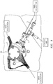
Figure 2 is an expanded perspective view of a duct of the gas turbine engine with a modular egress seal assembly; -
Figure 3 is an expanded view of the modular egress seal assembly; -
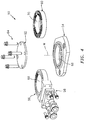
Figure 4 is an exploded view of the modular egress seal assembly according to an embodiment of the present invention; -
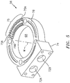
Figure 5 is an expanded perspective view of an egress seal annular plate of the modular egress seal assembly; -
Figure 6 is an expanded perspective view of an egress seal fitting assembly of the modular egress seal assembly; -
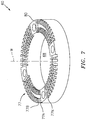
Figure 7 is an expanded perspective view of an instrumentation annular plate of the modular egress seal assembly; -
Figure 8 is an expanded perspective view of the modular egress seal assembly assembled according to one arrangement; -
Figure 9 is an expanded perspective view of an exemplary modular egress seal assembly assembled according to another arrangement not forming part of the invention; -
Figure 10 is an expanded perspective view of another exemplary modular egress seal assembly assembled according to another arrangement not forming part of the invention; and -
Figure 11 is an expanded perspective view of yet another exemplary modular egress seal assembly assembled according to another arrangement not forming part of the invention. -
Figure 1 schematically illustrates agas turbine engine 20. Thegas turbine engine 20 is disclosed herein as a two-spool low-bypass augmented turbofan that generally incorporates afan section 22, acompressor section 24, acombustor section 26, aturbine section 28, an augmenter (afterburner)section 30, anexhaust duct section 32, and anozzle system 34 along a central longitudinal engine axis A. Although depicted as an augmented low bypass turbofan in the disclosed non-limiting embodiment, it should be understood that the concepts described herein are applicable to other gas turbine engines including non-augmented engines, geared architecture engines, direct drive turbofans, turbojet, turboshaft, multi-stream variable cycle and other engine architectures. - An
outer structure 36 and aninner structure 38 define a generally annularsecondary airflow path 40 around a coreprimary airflow path 42. Various structure and modules may define theouter structure 36 and theinner structure 38 which essentially define an exoskeleton to support the rotational hardware therein. - With reference to
Figure 2 , a modularegress seal assembly 50 operates to seal a multiple of instrumentation leads L from, for example only, aduct 44 such as a forward augmentor duct of the augmenter section 30 (Figure 1 ). The modularegress seal assembly 50 provides for selective sealed egress of a multiple of instrumentation leads L from thermocouples or other sensors through aninstrumentation port 46. The modularegress seal assembly 50 in one disclosed non-limiting embodiment provides a variable instrumentation count such as, for example, 12-60 leads L and two (2) pressure transducers K such as those manufactured by Kulite Semiconductor Products, Inc. of New Jersey USA. - With reference to
Figure 3 , the pressure transducers K also communicate through lead wires L which may or may not be located within an armored conduit T through which cooling air may be communicated. It should be appreciated that many different types and numbers of instrumentation leads, wires, air-cooled conduits, non air-cooled conduits and other communication paths may be alternatively or additionally accommodated. - With reference to
Figure 4 , the modularegress seal assembly 50 according to an embodiment of the present invention generally includes abase plate 54, an egress sealannular plate 56, an egressseal fitting assembly 58, an instrumentationannular plate 60, acover plate 62 and a multiple offasteners 64. It should be appreciated that many different types of plates may alternatively or additionally be provided. - The
base plate 54 receives one or more of theannular plates cover plate 62 and retained by thefasteners 64. Thebase plate 54, the egress sealannular plate 56 and the instrumentationannular plate 60 generally includes arespective aperture apertures Figure 3 ). - With reference to
Figure 5 , the egress sealannular plate 56 includes a multiple - two shown - offitting apertures aperture 68. Thefitting apertures block 74 onto which the egressseal fitting assembly 58 is fastened to receive sensors, such as pressure transducers (not shown), andair cooling conduits Figure 6 ). The egress sealannular plate 56 also includes an instrumentation lead through-slot array 75 with a multiple of instrumentation lead through-slots top surface 78 thereof in communication with theaperture 68. In one disclosed non-limiting embodiment, twelve instrumentation lead through-slots 75 are provided, however, any number will benefit herefrom. Each of the multiple of instrumentation lead through-slots 75A-75n is capable of routing, for example, a thermocouple lead that may be sealed therein by a high-temp, e.g., about 1800F (538C) capability potting material. It should be appreciated that unused instrumentation lead through-slots 75 may be completely filled and closed off with potting compound or other seal. - With reference to
Figure 7 , the instrumentationannular plate 60 includes an instrumentation lead through-slot array 77 with a multiple of instrumentation lead through-slots top surface 80 thereof in communication with theaperture 68. In one disclosed non-limiting embodiment, a forty-eight instrumentation lead through-slots array 77 is provided around thetop surface 80 provided, however, any number will benefit herefrom. - Assembly of the egress seal
annular plate 56, the instrumentationannular plate 60 and thecover plate 62 to thebase plate 54 according to the method of the present invention provides for egress of, for example, sixty total instrumentation lead through-slots fitting apertures Figure 8 ). Alternately, assembly of the egress sealannular plate 56, and thecover plate 62 to thebase plate 54 provides for egress of twelve instrumentation lead through-slots 75 and twofitting apertures Figure 9 that does not form part of the invention. Alternately, assembly of the instrumentationannular plate 60 and thecover plate 62 to thebase plate 54 provides for egress of forty-eight instrumentation lead through-slots 75 as shown in the example ofFigure 10 that does not form part of the invention. Alternately, assembly of thecover plate 62 to thebase plate 54 seals the forward augmentor duct 52 as shown in the example ofFigure 11 that does not form part of the invention. This list of alternatives is not exclusive. It should be appreciated that although only one of each plate is disclosed in the various alternative examples, any number of plates may be combined to provide a desired instrumentation egress combination. - The modular
egress seal assembly 50 facilitates the egress of significant numbers of instrumentation leads L through a relatively small instrumentation port which, in a disclosed non-limiting embodiment may be of only 2 inches (50mm) diameter. Furthermore, the modularity facilitates development as the instrumentation needs may change and the port may eventfully be sealed with thecover plate 62 when instrumentation is no longer required. - It should be understood that like reference numerals identify corresponding or similar elements throughout the several drawings. It should also be understood that although a particular component arrangement is disclosed in the illustrated embodiment, other arrangements will benefit herefrom.
- Although the different examples and embodiments have specific illustrated components, the embodiments of this invention are not limited to those particular combinations. It is possible to use some of the components or features from any of the non-limiting embodiments in combination with features or components from any of the other non-limiting embodiments.
- Although particular step sequences are shown, described, and claimed, it should be understood that steps may be performed in any order, separated or combined unless otherwise indicated and will still benefit from the present disclosure.
- The foregoing description is exemplary rather than defined by the limitations within. Various examples and embodiments are disclosed herein, however, one of ordinary skill in the art would recognize that various modifications and variations in light of the above teachings will fall within the scope of the appended claims. It is therefore to be understood that within the scope of the appended claims, the disclosure may be practiced other than as specifically described. For that reason the appended claims should be studied to determine true scope and content.
Claims (11)
- A modular egress seal assembly (50) for a gas turbine engine comprising:an egress seal annular plate (56) with an aperture (68) defined about an egress seal axis (W);abase plate (54) including an aperture (66) extending along the axis (W);an instrumentation annular plate (60) including an aperture (70) extending along the axis (W);a cover plate (62); andan egress seal fitting assembly (58),characterized in that:a first one of the egress seal annular plate (56) or the instrumentation annular plate (60) is mounted to the base plate (54), thereby forming an axial passageway; the other one of the egress seal annular plate (56) or the instrumentation annular plate (60) is mounted to the first one, on top of which is mounted the cover plate (62); the egress seal annular plate (56) includes at least one fitting aperture (72A, 72B) transverse to the axis (W) and in communication with the aperture (68) of the egress seal annular plate (56); andthe at least one fitting aperture (72A, 72B) is air-cooled and located within a block (74) onto which the egress seal fitting assembly (58) is fastened to receive sensors and air cooling conduits (74A, 74B).
- The assembly as recited in claim 1, wherein the egress seal annular plate (56) and the instrumentation annular plate (60) include a multiple of instrumentation lead through-slots (75, 77) on a top surface (78, 80) thereof.
- The assembly as recited in claim 1, wherein the egress seal annular plate (56) includes a multiple of stacked egress seal annular plates (56), wherein at least one of the multiple of stacked egress seal annular plates (56) includes the at least one fitting aperture (72A, 72B).
- The assembly as recited in claim 3, wherein at least one of the multiple of stacked egress seal annular plates (56) includes a multiple of instrumentation lead through-slots (75) on a top surface (78) thereof.
- The assembly as recited in claim 1, wherein the at least one fitting aperture (72A, 72B) includes two fitting apertures within the block (74).
- The assembly as recited in claim 1,
wherein the egress seal annular plate (56) includes an instrumentation lead through-slot array (75) with a multiple of instrumentation lead through-slots (75A, 75B, ... 75n) along a top surface (78) thereof in communication with the aperture (68) of the egress seal annular plate (56),
wherein each of the multiple of instrumentation lead through-slots (75A, 75B, ... 75n) is capable of routing a lead (L) therethrough. - A gas turbine engine (20) comprising:a duct (44) with an instrumentation port (46); anda modular egress seal assembly (50) as claimed in any preceding claim mounted to the instrumentation port (46) along the axis (W).
- A method of installing a modular egress seal assembly (50) to an instrumentation port (46) in a gas turbine engine (20) comprising:mounting a first one of an egress seal annular plate (56) or an instrumentation annular plate (60) to a base plate (54) that surrounds an instrumentation port (46), where the egress seal annular plate (56) includes an aperture (68) defined about an egress seal axis (W), and where the instrumentation annular plate (60) includes an aperture (70) defined about the axis (W); mounting the other one of the egress seal annular plate (56) or the instrumentation annular plate (60) to the first one; fastening an egress seal fitting assembly (58) onto a block (74) to receive sensors and air cooling conduits (74A, 74B), the egress seal annular plate (56) including at least one fitting aperture (72A, 72B) transverse to the axis (W) and in communication with the aperture (68) of the egress seal annular plate (56), wherein the at least one fitting aperture (72A, 72B) is air-cooled and located within the block (74); and topping said annular plates (56, 60) with a cover plate (62), thereby providing an axial passage into the instrumentation port (46).
- The method as recited in claim 8, further comprising:mounting said annular plates (56, 60) or a multiple of said annular plates (56, 60) to the base plate (54) with a multiple of fasteners (64) which extend therethrough from the cover plate (62) to the base plate (54).
- The method as recited in claim 8 or 9, further comprising:threading an instrumentation lead (L) through one of one or more instrumentation lead through-slots (75, 77) located in a top surface (78, 80) of the egress seal annular plate (56) and the instrumentation annular plate (60) and extending to the aperture (68, 70) of the respective egress seal annular plate (56) and/or the instrumentation annular plate (60).
- The method as recited in claim 10, further comprising:sealing the instrumentation lead (L) in the instrumentation lead through-slot (75, 77) with a potting compound.
Applications Claiming Priority (2)
| Application Number | Priority Date | Filing Date | Title |
|---|---|---|---|
| US201361768961P | 2013-02-25 | 2013-02-25 | |
| PCT/US2014/018148 WO2014130980A1 (en) | 2013-02-25 | 2014-02-25 | Modular instrumentation egress seal for a gas turbine engine |
Publications (3)
| Publication Number | Publication Date |
|---|---|
| EP2959137A1 EP2959137A1 (en) | 2015-12-30 |
| EP2959137A4 EP2959137A4 (en) | 2016-11-02 |
| EP2959137B1 true EP2959137B1 (en) | 2017-11-29 |
Family
ID=51391903
Family Applications (1)
| Application Number | Title | Priority Date | Filing Date |
|---|---|---|---|
| EP14753888.8A Active EP2959137B1 (en) | 2013-02-25 | 2014-02-25 | Modular instrumentation egress seal assembly for a gas turbine engine |
Country Status (3)
| Country | Link |
|---|---|
| US (1) | US10107124B2 (en) |
| EP (1) | EP2959137B1 (en) |
| WO (1) | WO2014130980A1 (en) |
Families Citing this family (7)
| Publication number | Priority date | Publication date | Assignee | Title |
|---|---|---|---|---|
| US20170342910A1 (en) * | 2016-05-25 | 2017-11-30 | General Electric Company | Attachment system for a gas turbine engine |
| GB2560312B (en) | 2017-03-06 | 2021-06-09 | Rolls Royce Plc | An electrical connector arrangement |
| GB2574693B (en) * | 2019-02-04 | 2021-02-24 | Rolls Royce Plc | Gas turbine engine shaft break mitigation |
| GB2574495B (en) * | 2019-02-04 | 2021-02-17 | Rolls Royce Plc | Gas turbine engine shaft break mitigation |
| CN115264063B (en) * | 2022-08-25 | 2025-09-02 | 深圳市深科达半导体科技有限公司 | Gas distribution plate assembly and gas distribution device |
| US12345168B2 (en) * | 2023-11-27 | 2025-07-01 | Rtx Corporation | Fitting for an instrument lead with a connector for a gas turbine engine |
| US20260125989A1 (en) * | 2024-11-07 | 2026-05-07 | Rtx Corporation | Cooling restoration for instrumented blade outer air seal |
Family Cites Families (10)
| Publication number | Priority date | Publication date | Assignee | Title |
|---|---|---|---|---|
| US4267401A (en) | 1978-07-03 | 1981-05-12 | Wilkinson William L | Seal plug |
| US4244221A (en) * | 1979-02-01 | 1981-01-13 | General Electric Company | Removable instrumentation probe |
| US4580910A (en) * | 1985-01-24 | 1986-04-08 | National Flight Services, Inc. | Engine exhaust gas test harness |
| EP1751456A1 (en) | 2004-06-02 | 2007-02-14 | GL Tool and Manufacturing Co. Inc. | A bulkhead connector |
| US7939769B2 (en) | 2006-11-27 | 2011-05-10 | Jetseal, Inc. | Sensor pass through assembly |
| US20100079136A1 (en) * | 2008-09-29 | 2010-04-01 | Rosemount Aerospace Inc. | Blade tip clearance measurement sensor and method for gas turbine engines |
| US20100158074A1 (en) * | 2008-12-19 | 2010-06-24 | Rejean Fortier | Multipoint probe assembly and method |
| US8109159B1 (en) | 2009-06-23 | 2012-02-07 | Turbine Technologies, Inc. | Instrumentation installation tool for a pressure vessel test rig |
| US20110277569A1 (en) | 2010-05-14 | 2011-11-17 | Douglas Rush | Instrumentation fitting |
| US20120216608A1 (en) * | 2011-02-25 | 2012-08-30 | General Electric Company | System for measuring parameters of fluid flow in turbomachinery |
-
2014
- 2014-02-25 WO PCT/US2014/018148 patent/WO2014130980A1/en not_active Ceased
- 2014-02-25 EP EP14753888.8A patent/EP2959137B1/en active Active
- 2014-02-25 US US14/770,361 patent/US10107124B2/en active Active
Non-Patent Citations (1)
| Title |
|---|
| None * |
Also Published As
| Publication number | Publication date |
|---|---|
| WO2014130980A1 (en) | 2014-08-28 |
| EP2959137A4 (en) | 2016-11-02 |
| EP2959137A1 (en) | 2015-12-30 |
| US10107124B2 (en) | 2018-10-23 |
| US20160010479A1 (en) | 2016-01-14 |
Similar Documents
| Publication | Publication Date | Title |
|---|---|---|
| US10107124B2 (en) | Modular instrumentation egress seal for a gas turbine engine | |
| US8944749B2 (en) | Oil purge system for a mid turbine frame | |
| US8740554B2 (en) | Cover plate with interstage seal for a gas turbine engine | |
| US10174632B2 (en) | Borescope plug assembly for gas turbine engine | |
| US10309255B2 (en) | Blade outer air seal cooling passage | |
| US10989111B2 (en) | Turbine minidisk bumper for gas turbine engine | |
| EP2971688A1 (en) | Heatshield discourager seal for a gas turbine engine | |
| EP3085899B1 (en) | Gas turbine engine mid turbine frame including a sealed torque box | |
| EP4286659B1 (en) | Borescope plug assembly | |
| US9765649B2 (en) | Borescope inspection port fitting | |
| US9856748B2 (en) | Probe tip cooling | |
| US20260098481A1 (en) | Systems and methods for identifying a condition of gas turbine engine seals | |
| US20160115800A1 (en) | Stator assembly with pad interface for a gas turbine engine | |
| US9988982B2 (en) | Turbine engine with a combustion chamber outer flange of sandwich type | |
| US20170138270A1 (en) | Instrumentation adaptor for a gas turbine engine | |
| US10724402B2 (en) | Gas turbine duct liner coupling assembly | |
| US9835091B2 (en) | Multiple piece shroud feedthru enclosure |
Legal Events
| Date | Code | Title | Description |
|---|---|---|---|
| PUAI | Public reference made under article 153(3) epc to a published international application that has entered the european phase |
Free format text: ORIGINAL CODE: 0009012 |
|
| 17P | Request for examination filed |
Effective date: 20150916 |
|
| AK | Designated contracting states |
Kind code of ref document: A1 Designated state(s): AL AT BE BG CH CY CZ DE DK EE ES FI FR GB GR HR HU IE IS IT LI LT LU LV MC MK MT NL NO PL PT RO RS SE SI SK SM TR |
|
| AX | Request for extension of the european patent |
Extension state: BA ME |
|
| DAX | Request for extension of the european patent (deleted) | ||
| REG | Reference to a national code |
Ref country code: DE Ref legal event code: R079 Ref document number: 602014017929 Country of ref document: DE Free format text: PREVIOUS MAIN CLASS: F02C0007280000 Ipc: F01D0017020000 |
|
| RAP1 | Party data changed (applicant data changed or rights of an application transferred) |
Owner name: UNITED TECHNOLOGIES CORPORATION |
|
| A4 | Supplementary search report drawn up and despatched |
Effective date: 20161005 |
|
| RIC1 | Information provided on ipc code assigned before grant |
Ipc: G01M 15/14 20060101ALI20160928BHEP Ipc: F01D 17/02 20060101AFI20160928BHEP |
|
| GRAP | Despatch of communication of intention to grant a patent |
Free format text: ORIGINAL CODE: EPIDOSNIGR1 |
|
| STAA | Information on the status of an ep patent application or granted ep patent |
Free format text: STATUS: GRANT OF PATENT IS INTENDED |
|
| INTG | Intention to grant announced |
Effective date: 20170616 |
|
| GRAS | Grant fee paid |
Free format text: ORIGINAL CODE: EPIDOSNIGR3 |
|
| GRAA | (expected) grant |
Free format text: ORIGINAL CODE: 0009210 |
|
| STAA | Information on the status of an ep patent application or granted ep patent |
Free format text: STATUS: THE PATENT HAS BEEN GRANTED |
|
| AK | Designated contracting states |
Kind code of ref document: B1 Designated state(s): AL AT BE BG CH CY CZ DE DK EE ES FI FR GB GR HR HU IE IS IT LI LT LU LV MC MK MT NL NO PL PT RO RS SE SI SK SM TR |
|
| REG | Reference to a national code |
Ref country code: CH Ref legal event code: EP |
|
| REG | Reference to a national code |
Ref country code: AT Ref legal event code: REF Ref document number: 950590 Country of ref document: AT Kind code of ref document: T Effective date: 20171215 |
|
| REG | Reference to a national code |
Ref country code: IE Ref legal event code: FG4D |
|
| REG | Reference to a national code |
Ref country code: DE Ref legal event code: R096 Ref document number: 602014017929 Country of ref document: DE |
|
| REG | Reference to a national code |
Ref country code: FR Ref legal event code: PLFP Year of fee payment: 5 |
|
| REG | Reference to a national code |
Ref country code: NL Ref legal event code: MP Effective date: 20171129 |
|
| REG | Reference to a national code |
Ref country code: LT Ref legal event code: MG4D |
|
| REG | Reference to a national code |
Ref country code: AT Ref legal event code: MK05 Ref document number: 950590 Country of ref document: AT Kind code of ref document: T Effective date: 20171129 |
|
| PG25 | Lapsed in a contracting state [announced via postgrant information from national office to epo] |
Ref country code: LT Free format text: LAPSE BECAUSE OF FAILURE TO SUBMIT A TRANSLATION OF THE DESCRIPTION OR TO PAY THE FEE WITHIN THE PRESCRIBED TIME-LIMIT Effective date: 20171129 Ref country code: ES Free format text: LAPSE BECAUSE OF FAILURE TO SUBMIT A TRANSLATION OF THE DESCRIPTION OR TO PAY THE FEE WITHIN THE PRESCRIBED TIME-LIMIT Effective date: 20171129 Ref country code: NO Free format text: LAPSE BECAUSE OF FAILURE TO SUBMIT A TRANSLATION OF THE DESCRIPTION OR TO PAY THE FEE WITHIN THE PRESCRIBED TIME-LIMIT Effective date: 20180228 Ref country code: FI Free format text: LAPSE BECAUSE OF FAILURE TO SUBMIT A TRANSLATION OF THE DESCRIPTION OR TO PAY THE FEE WITHIN THE PRESCRIBED TIME-LIMIT Effective date: 20171129 Ref country code: SE Free format text: LAPSE BECAUSE OF FAILURE TO SUBMIT A TRANSLATION OF THE DESCRIPTION OR TO PAY THE FEE WITHIN THE PRESCRIBED TIME-LIMIT Effective date: 20171129 |
|
| PG25 | Lapsed in a contracting state [announced via postgrant information from national office to epo] |
Ref country code: HR Free format text: LAPSE BECAUSE OF FAILURE TO SUBMIT A TRANSLATION OF THE DESCRIPTION OR TO PAY THE FEE WITHIN THE PRESCRIBED TIME-LIMIT Effective date: 20171129 Ref country code: AT Free format text: LAPSE BECAUSE OF FAILURE TO SUBMIT A TRANSLATION OF THE DESCRIPTION OR TO PAY THE FEE WITHIN THE PRESCRIBED TIME-LIMIT Effective date: 20171129 Ref country code: LV Free format text: LAPSE BECAUSE OF FAILURE TO SUBMIT A TRANSLATION OF THE DESCRIPTION OR TO PAY THE FEE WITHIN THE PRESCRIBED TIME-LIMIT Effective date: 20171129 Ref country code: GR Free format text: LAPSE BECAUSE OF FAILURE TO SUBMIT A TRANSLATION OF THE DESCRIPTION OR TO PAY THE FEE WITHIN THE PRESCRIBED TIME-LIMIT Effective date: 20180301 Ref country code: RS Free format text: LAPSE BECAUSE OF FAILURE TO SUBMIT A TRANSLATION OF THE DESCRIPTION OR TO PAY THE FEE WITHIN THE PRESCRIBED TIME-LIMIT Effective date: 20171129 Ref country code: BG Free format text: LAPSE BECAUSE OF FAILURE TO SUBMIT A TRANSLATION OF THE DESCRIPTION OR TO PAY THE FEE WITHIN THE PRESCRIBED TIME-LIMIT Effective date: 20180228 |
|
| PG25 | Lapsed in a contracting state [announced via postgrant information from national office to epo] |
Ref country code: NL Free format text: LAPSE BECAUSE OF FAILURE TO SUBMIT A TRANSLATION OF THE DESCRIPTION OR TO PAY THE FEE WITHIN THE PRESCRIBED TIME-LIMIT Effective date: 20171129 |
|
| PG25 | Lapsed in a contracting state [announced via postgrant information from national office to epo] |
Ref country code: DK Free format text: LAPSE BECAUSE OF FAILURE TO SUBMIT A TRANSLATION OF THE DESCRIPTION OR TO PAY THE FEE WITHIN THE PRESCRIBED TIME-LIMIT Effective date: 20171129 Ref country code: CY Free format text: LAPSE BECAUSE OF FAILURE TO SUBMIT A TRANSLATION OF THE DESCRIPTION OR TO PAY THE FEE WITHIN THE PRESCRIBED TIME-LIMIT Effective date: 20171129 Ref country code: CZ Free format text: LAPSE BECAUSE OF FAILURE TO SUBMIT A TRANSLATION OF THE DESCRIPTION OR TO PAY THE FEE WITHIN THE PRESCRIBED TIME-LIMIT Effective date: 20171129 Ref country code: SK Free format text: LAPSE BECAUSE OF FAILURE TO SUBMIT A TRANSLATION OF THE DESCRIPTION OR TO PAY THE FEE WITHIN THE PRESCRIBED TIME-LIMIT Effective date: 20171129 Ref country code: EE Free format text: LAPSE BECAUSE OF FAILURE TO SUBMIT A TRANSLATION OF THE DESCRIPTION OR TO PAY THE FEE WITHIN THE PRESCRIBED TIME-LIMIT Effective date: 20171129 |
|
| REG | Reference to a national code |
Ref country code: DE Ref legal event code: R097 Ref document number: 602014017929 Country of ref document: DE |
|
| PG25 | Lapsed in a contracting state [announced via postgrant information from national office to epo] |
Ref country code: PL Free format text: LAPSE BECAUSE OF FAILURE TO SUBMIT A TRANSLATION OF THE DESCRIPTION OR TO PAY THE FEE WITHIN THE PRESCRIBED TIME-LIMIT Effective date: 20171129 Ref country code: RO Free format text: LAPSE BECAUSE OF FAILURE TO SUBMIT A TRANSLATION OF THE DESCRIPTION OR TO PAY THE FEE WITHIN THE PRESCRIBED TIME-LIMIT Effective date: 20171129 Ref country code: SM Free format text: LAPSE BECAUSE OF FAILURE TO SUBMIT A TRANSLATION OF THE DESCRIPTION OR TO PAY THE FEE WITHIN THE PRESCRIBED TIME-LIMIT Effective date: 20171129 Ref country code: IT Free format text: LAPSE BECAUSE OF FAILURE TO SUBMIT A TRANSLATION OF THE DESCRIPTION OR TO PAY THE FEE WITHIN THE PRESCRIBED TIME-LIMIT Effective date: 20171129 |
|
| REG | Reference to a national code |
Ref country code: CH Ref legal event code: PL |
|
| PG25 | Lapsed in a contracting state [announced via postgrant information from national office to epo] |
Ref country code: MC Free format text: LAPSE BECAUSE OF FAILURE TO SUBMIT A TRANSLATION OF THE DESCRIPTION OR TO PAY THE FEE WITHIN THE PRESCRIBED TIME-LIMIT Effective date: 20171129 |
|
| PLBE | No opposition filed within time limit |
Free format text: ORIGINAL CODE: 0009261 |
|
| STAA | Information on the status of an ep patent application or granted ep patent |
Free format text: STATUS: NO OPPOSITION FILED WITHIN TIME LIMIT |
|
| 26N | No opposition filed |
Effective date: 20180830 |
|
| REG | Reference to a national code |
Ref country code: IE Ref legal event code: MM4A |
|
| REG | Reference to a national code |
Ref country code: BE Ref legal event code: MM Effective date: 20180228 |
|
| PG25 | Lapsed in a contracting state [announced via postgrant information from national office to epo] |
Ref country code: SI Free format text: LAPSE BECAUSE OF FAILURE TO SUBMIT A TRANSLATION OF THE DESCRIPTION OR TO PAY THE FEE WITHIN THE PRESCRIBED TIME-LIMIT Effective date: 20171129 Ref country code: CH Free format text: LAPSE BECAUSE OF NON-PAYMENT OF DUE FEES Effective date: 20180228 Ref country code: LI Free format text: LAPSE BECAUSE OF NON-PAYMENT OF DUE FEES Effective date: 20180228 Ref country code: LU Free format text: LAPSE BECAUSE OF NON-PAYMENT OF DUE FEES Effective date: 20180225 |
|
| PG25 | Lapsed in a contracting state [announced via postgrant information from national office to epo] |
Ref country code: IE Free format text: LAPSE BECAUSE OF NON-PAYMENT OF DUE FEES Effective date: 20180225 |
|
| PG25 | Lapsed in a contracting state [announced via postgrant information from national office to epo] |
Ref country code: BE Free format text: LAPSE BECAUSE OF NON-PAYMENT OF DUE FEES Effective date: 20180228 |
|
| PG25 | Lapsed in a contracting state [announced via postgrant information from national office to epo] |
Ref country code: MT Free format text: LAPSE BECAUSE OF NON-PAYMENT OF DUE FEES Effective date: 20180225 |
|
| PG25 | Lapsed in a contracting state [announced via postgrant information from national office to epo] |
Ref country code: TR Free format text: LAPSE BECAUSE OF FAILURE TO SUBMIT A TRANSLATION OF THE DESCRIPTION OR TO PAY THE FEE WITHIN THE PRESCRIBED TIME-LIMIT Effective date: 20171129 |
|
| PG25 | Lapsed in a contracting state [announced via postgrant information from national office to epo] |
Ref country code: PT Free format text: LAPSE BECAUSE OF FAILURE TO SUBMIT A TRANSLATION OF THE DESCRIPTION OR TO PAY THE FEE WITHIN THE PRESCRIBED TIME-LIMIT Effective date: 20171129 |
|
| PG25 | Lapsed in a contracting state [announced via postgrant information from national office to epo] |
Ref country code: MK Free format text: LAPSE BECAUSE OF NON-PAYMENT OF DUE FEES Effective date: 20171129 Ref country code: HU Free format text: LAPSE BECAUSE OF FAILURE TO SUBMIT A TRANSLATION OF THE DESCRIPTION OR TO PAY THE FEE WITHIN THE PRESCRIBED TIME-LIMIT; INVALID AB INITIO Effective date: 20140225 |
|
| PG25 | Lapsed in a contracting state [announced via postgrant information from national office to epo] |
Ref country code: AL Free format text: LAPSE BECAUSE OF FAILURE TO SUBMIT A TRANSLATION OF THE DESCRIPTION OR TO PAY THE FEE WITHIN THE PRESCRIBED TIME-LIMIT Effective date: 20171129 Ref country code: IS Free format text: LAPSE BECAUSE OF FAILURE TO SUBMIT A TRANSLATION OF THE DESCRIPTION OR TO PAY THE FEE WITHIN THE PRESCRIBED TIME-LIMIT Effective date: 20180329 |
|
| REG | Reference to a national code |
Ref country code: DE Ref legal event code: R081 Ref document number: 602014017929 Country of ref document: DE Owner name: RAYTHEON TECHNOLOGIES CORPORATION (N.D.GES.D.S, US Free format text: FORMER OWNER: UNITED TECHNOLOGIES CORPORATION, FARMINGTON, CONN., US Ref country code: DE Ref legal event code: R081 Ref document number: 602014017929 Country of ref document: DE Owner name: RTX CORPORATION (N.D.GES.D. STAATES DELAWARE),, US Free format text: FORMER OWNER: UNITED TECHNOLOGIES CORPORATION, FARMINGTON, CONN., US |
|
| P01 | Opt-out of the competence of the unified patent court (upc) registered |
Effective date: 20230520 |
|
| REG | Reference to a national code |
Ref country code: DE Ref legal event code: R081 Ref document number: 602014017929 Country of ref document: DE Owner name: RTX CORPORATION (N.D.GES.D. STAATES DELAWARE),, US Free format text: FORMER OWNER: RAYTHEON TECHNOLOGIES CORPORATION (N.D.GES.D.STAATES DELAWARE), ARLINGTON, VA, US |
|
| PGFP | Annual fee paid to national office [announced via postgrant information from national office to epo] |
Ref country code: GB Payment date: 20260121 Year of fee payment: 13 |
|
| PGFP | Annual fee paid to national office [announced via postgrant information from national office to epo] |
Ref country code: DE Payment date: 20260121 Year of fee payment: 13 |
|
| PGFP | Annual fee paid to national office [announced via postgrant information from national office to epo] |
Ref country code: FR Payment date: 20260121 Year of fee payment: 13 |