EP2958659B2 - Method for removing ammonia from a vent gas stream of a urea plant - Google Patents
Method for removing ammonia from a vent gas stream of a urea plant Download PDFInfo
- Publication number
- EP2958659B2 EP2958659B2 EP14716000.6A EP14716000A EP2958659B2 EP 2958659 B2 EP2958659 B2 EP 2958659B2 EP 14716000 A EP14716000 A EP 14716000A EP 2958659 B2 EP2958659 B2 EP 2958659B2
- Authority
- EP
- European Patent Office
- Prior art keywords
- combustion
- ammonia
- oxygen
- gas stream
- oxidation
- Prior art date
- Legal status (The legal status is an assumption and is not a legal conclusion. Google has not performed a legal analysis and makes no representation as to the accuracy of the status listed.)
- Active
Links
Images

Classifications
-
- B—PERFORMING OPERATIONS; TRANSPORTING
- B01—PHYSICAL OR CHEMICAL PROCESSES OR APPARATUS IN GENERAL
- B01D—SEPARATION
- B01D53/00—Separation of gases or vapours; Recovering vapours of volatile solvents from gases; Chemical or biological purification of waste gases, e.g. engine exhaust gases, smoke, fumes, flue gases, aerosols
- B01D53/34—Chemical or biological purification of waste gases
- B01D53/46—Removing components of defined structure
- B01D53/54—Nitrogen compounds
- B01D53/58—Ammonia
-
- B—PERFORMING OPERATIONS; TRANSPORTING
- B01—PHYSICAL OR CHEMICAL PROCESSES OR APPARATUS IN GENERAL
- B01D—SEPARATION
- B01D53/00—Separation of gases or vapours; Recovering vapours of volatile solvents from gases; Chemical or biological purification of waste gases, e.g. engine exhaust gases, smoke, fumes, flue gases, aerosols
- B01D53/34—Chemical or biological purification of waste gases
- B01D53/74—General processes for purification of waste gases; Apparatus or devices specially adapted therefor
- B01D53/86—Catalytic processes
- B01D53/8621—Removing nitrogen compounds
- B01D53/8634—Ammonia
-
- B—PERFORMING OPERATIONS; TRANSPORTING
- B01—PHYSICAL OR CHEMICAL PROCESSES OR APPARATUS IN GENERAL
- B01D—SEPARATION
- B01D53/00—Separation of gases or vapours; Recovering vapours of volatile solvents from gases; Chemical or biological purification of waste gases, e.g. engine exhaust gases, smoke, fumes, flue gases, aerosols
- B01D53/34—Chemical or biological purification of waste gases
- B01D53/74—General processes for purification of waste gases; Apparatus or devices specially adapted therefor
- B01D53/86—Catalytic processes
- B01D53/90—Injecting reactants
-
- C—CHEMISTRY; METALLURGY
- C07—ORGANIC CHEMISTRY
- C07C—ACYCLIC OR CARBOCYCLIC COMPOUNDS
- C07C273/00—Preparation of urea or its derivatives, i.e. compounds containing any of the groups, the nitrogen atoms not being part of nitro or nitroso groups
- C07C273/02—Preparation of urea or its derivatives, i.e. compounds containing any of the groups, the nitrogen atoms not being part of nitro or nitroso groups of urea, its salts, complexes or addition compounds
- C07C273/04—Preparation of urea or its derivatives, i.e. compounds containing any of the groups, the nitrogen atoms not being part of nitro or nitroso groups of urea, its salts, complexes or addition compounds from carbon dioxide and ammonia
-
- B—PERFORMING OPERATIONS; TRANSPORTING
- B01—PHYSICAL OR CHEMICAL PROCESSES OR APPARATUS IN GENERAL
- B01D—SEPARATION
- B01D2251/00—Reactants
- B01D2251/10—Oxidants
- B01D2251/102—Oxygen
-
- B—PERFORMING OPERATIONS; TRANSPORTING
- B01—PHYSICAL OR CHEMICAL PROCESSES OR APPARATUS IN GENERAL
- B01D—SEPARATION
- B01D2251/00—Reactants
- B01D2251/10—Oxidants
- B01D2251/11—Air
-
- B—PERFORMING OPERATIONS; TRANSPORTING
- B01—PHYSICAL OR CHEMICAL PROCESSES OR APPARATUS IN GENERAL
- B01D—SEPARATION
- B01D2251/00—Reactants
- B01D2251/20—Reductants
-
- B—PERFORMING OPERATIONS; TRANSPORTING
- B01—PHYSICAL OR CHEMICAL PROCESSES OR APPARATUS IN GENERAL
- B01D—SEPARATION
- B01D2257/00—Components to be removed
- B01D2257/40—Nitrogen compounds
- B01D2257/406—Ammonia
-
- Y—GENERAL TAGGING OF NEW TECHNOLOGICAL DEVELOPMENTS; GENERAL TAGGING OF CROSS-SECTIONAL TECHNOLOGIES SPANNING OVER SEVERAL SECTIONS OF THE IPC; TECHNICAL SUBJECTS COVERED BY FORMER USPC CROSS-REFERENCE ART COLLECTIONS [XRACs] AND DIGESTS
- Y02—TECHNOLOGIES OR APPLICATIONS FOR MITIGATION OR ADAPTATION AGAINST CLIMATE CHANGE
- Y02A—TECHNOLOGIES FOR ADAPTATION TO CLIMATE CHANGE
- Y02A50/00—TECHNOLOGIES FOR ADAPTATION TO CLIMATE CHANGE in human health protection, e.g. against extreme weather
- Y02A50/20—Air quality improvement or preservation, e.g. vehicle emission control or emission reduction by using catalytic converters
Definitions
- the present invention relates to a method for removing ammonia from a continuous vent gas stream of a urea (i.e. urea production) plant.
- the invention relates to a method for removing small amounts of ammonia from a continuous vent gas stream of a medium-pressure section of a urea plant.
- urea is produced industrially using processes based on the high-temperature, high-pressure reaction of carbon dioxide and ammonia to form ammonium carbamate, and on the subsequent decomposition reaction of the ammonium carbamate to form urea and water.
- urea (production) plant these processes are normally conducted in a synthesis section comprising a urea synthesis reactor; and the urea and water solution produced in the synthesis section is then concentrated gradually - the unconverted reactants being recovered in one or more recovery sections - and is solidified in follow-up finishing (e.g. prilling, granulating, ...) sections.
- the reactants which are recirculated to the synthesis section, are recovered in a number of sections, and more specifically in a high-pressure, medium-pressure, and low-pressure section.
- a urea production plant normally produces gas streams containing unconverted reactants, including non-reacted ammonia, and so produces vent gases containing ammonia.
- the medium-pressure section vents continuous gas streams containing small amounts of ammonia and hydrogen, as well as methane and inerts (mainly nitrogen). Depending on the process used in the urea production plant, these gas streams may also contain oxygen.
- the gas streams are normally mixed to conform with safety regulations, and more specifically to remain outside explosion limits.
- ammonia in the gas streams produced in the urea plant must therefore be removed before releasing the gas streams into the atmosphere.
- One fairly commonly used system for preventing ammonia emission into the atmosphere employs a torch, into which the gases (ammonia, methane, oxygen, hydrogen and inerts) from the medium-pressure section (or urea plant in general) are fed continuously.
- the gases are fed to the end of the torch, where a gas- (e.g. methane-) fuelled flame burns the ammonia in uncontrolled manner.
- Patent Application WO2012134288 describes a system based on the use of an incinerator, where a gas stream, rich in ammonia and hydrogen and coming from a urea production process not requiring passivating oxygen, is burned, producing a small amount of NOx; and the ammonia content is further removed, if necessary, using selective catalytic reduction (SCR) or selective non-catalytic reduction (SNCR) processes.
- SCR selective catalytic reduction
- SNCR selective non-catalytic reduction
- EP 2 505 581 describes a method of removing ammonia from a vent gas of a urea production plant, the vent gas being subjected to combustion.
- the present invention therefore relates to a method as defined in claim 1.
- the invention is intended to remove ammonia from oxygen-containing continuous vent gas streams from the urea production plant, wherein the urea production processes employ passivating oxygen, i.e. processes in which oxygen is added to the synthesis reactor supply to passivate metal (typically, stainless steel) surfaces.
- passivating oxygen i.e. processes in which oxygen is added to the synthesis reactor supply to passivate metal (typically, stainless steel) surfaces.
- urea production plants employing oxygen can be found in WO2010/006757 and WO2008/141832 .
- vent gas streams for treatment which are normally pre-mixed to remain below explosion limits
- the vent gas streams for treatment therefore substantially contain : ammonia, hydrogen, methane, inerts (mainly nitrogen), and even a significant percentage of oxygen (though still below explosion limits).
- the vent gas stream from a urea plant typically has the following composition (percentages in volume, 1200 Nm3/h at 50°C, 0.1 MPa(g)) :
- the passivating oxygen already present in the urea plant is exploited to remove ammonia.
- Ammonia is removed in at least two combustion stages preferably (though not necessarily) performed in one combustion environment.
- the combustion reaction is therefore performed in controlled manner in two steps or stages :
- Combustion in accordance with the invention is defined as controlled, in that dividing combustion into steps as described above controls the formation and elimination of nitric oxides (NOx), by means of understoichiometric combustion and the presence of hydrogen respectively, and so reduces nitric oxide emission into the atmosphere.
- NOx nitric oxides
- Controlled combustion in accordance with the invention does not actually need two combustion chambers.
- the two steps may be performed in one combustion environment, or in separate combustion chambers.
- the invention is implemented by a catalytic controlled combustion in two sections, with understoichiometric oxygen in the first section, and stoichiometric or overstoichiometric oxygen in the second section.
- the two combustion steps are performed by means of respective catalytic oxidations with no flame, and using appropriate respective catalysts.
- a heating resistor with no flame needed
- a predetermined activation temperature of about 150°C a predetermined activation temperature of about 150°C.
- no further heat or additional fuel is needed (as stated, the fuel needed is already present in the gas stream for treatment); and secondary air is only supplied at the second step, to sustain the reaction of the second catalyst.
- the first step employs catalysts (one or more) that promote understoichiometric catalytic oxidation of ammonia in a reducing atmosphere, and favour reaction (1) above over the others, particularly those forming nitric oxides, at temperatures ranging roughly between 150°C and 400°C.
- ammonia oxidation catalysts examples include those in the 'ammonia SCO' (ammonia Selective Catalytic Oxidation) class used for selective ammonia catalytic oxidation, and which are usable in this case, seeing as the continuous gas streams treated already contain the oxygen needed to burn the ammonia, and catalytic reactions (5) and (6) above are strongly favoured by the hydrogen already present in the gas streams, and which reduces the formation of nitric oxides (NOx) and eliminates the few formed.
- 'ammonia SCO' ammonia Selective Catalytic Oxidation
- part of the heat produced in the two catalytic beds may be recovered to produce steam or to preheat air for supply to the finishing unit (e.g. granulating or prilling unit, where the urea produced is formed into granules or prills) of the urea production plant.
- the finishing unit e.g. granulating or prilling unit, where the urea produced is formed into granules or prills
- An embodiment (B) not according to the claimed invention employs a premixed burner for controlled combustion in two steps or stages :
- Ammonia is oxidized at the first step, which employs the oxygen already present in the continuous gas streams from the urea production plant, thus enabling lean combustion (i.e., in the presence of understoichiometric oxygen, unlike the conventional torch system, in which combustion is performed in an excess of oxygen).
- Understoichiometric combustion enables a reduction in flame temperature with respect to overstoichiometric combustion (as in a torch), thus further reducing the formation of NOx.
- steam may be injected at the first oxidation step. Injecting steam further reduces the flame temperature, to impede the formation of nitric oxides.
- Methane and hydrogen combustion is completed at the second stage, in which secondary air or oxygen is supplied.
- Part of the combustion-generated heat may be recovered in a boiler for producing steam. Once the heat is recovered, the clean gases may be released into the atmosphere.
- all the heat generated in the premixed burner by combustion-oxidation may be recovered to heat the atomizing air for the granulating unit, or the fluidizing air for use in the urea plant prilling unit fluid beds (normally at a temperature of about 135°C), thus reducing cost by eliminating the need for a special steam air preheater.
- the vent gas stream for treatment is diverted to an integrated unit comprising a heat exchanger, e.g. plate type exchanger, and a catalytic cartridge containing the first-step (e.g. 'ammonia SCO') catalyst.
- a heat exchanger e.g. plate type exchanger
- a catalytic cartridge containing the first-step (e.g. 'ammonia SCO') catalyst.
- the catalyst provides for eliminating solely ammonia by understoichiometric combustion in a reducing atmosphere, and impeding the formation of nitric oxides.
- This embodiment does not include secondary-air supply and, therefore, the second combustion-oxidation step, in that the oxygen contained in the continuous gas streams from the urea plant is sufficient to completely oxidize the ammonia at the first (and only) step.
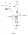
- Figure 1 shows a highly schematic, simplified block diagram of a urea (production) plant 1.
- Urea plant 1 is of the type described in WO2010/00675 and WO2008/141832 .
- Urea plant 1 substantially comprises : a synthesis section 2 with a urea synthesis reactor 3 where the urea synthesis reaction from ammonia and carbon dioxide takes place; recovery sections 4 - more specifically, a high-pressure section 5, medium-pressure section 6, and low-pressure section 7 - where the urea solution from synthesis section 2 is gradually concentrated, non-reacted ammonia and carbon dioxide are removed, and the recovered components are recirculated; and finishing sections 8 including at least one finishing unit, e.g. a granulating or prilling unit where the urea produced is formed into granules or prills.
- finishing unit e.g. a granulating or prilling unit where the urea produced is formed into granules or prills.
- each section and the lines supplying and recirculating the various gas streams from one section to another are not shown in detail in Figure 1 , which simply shows schematically the reactant feed lines to urea plant 1, and the operating connections between the sections.
- Urea plant 1 is equipped with an ammonia removal system 10 for processing ammonia-containing vent gas steams produced in urea plant 1.
- System 10 is connected to urea plant 1, e.g. to medium-pressure section 6 (or optionally to other sections), to tap a continuous vent gas stream.
- a typical continuous vent gas stream from medium-pressure section 6 of urea plant 1 contains ammonia, hydrogen, methane and inerts (mainly nitrogen).
- urea plant 1 implements a process employing passivating oxygen supplied to urea plant 1 by an air or oxygen feed line 11, and therefore the vent gas streams also contain oxygen.
- the vent gas stream fed to system 10 is of such a composition - possibly adjusted by mixing the various component streams - as to be outside explosion limits.
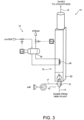
- system 10 comprises a treating unit 12 having a first and second oxidation section 13, 14; an inlet line 15 connecting treating unit 12 to urea plant 1 (more specifically, to medium-pressure section 6) and supplying treating unit 12 with the gas stream for treatment; an outlet line 16 for venting, e.g. into the atmosphere, the gas treated by treating unit 12; a secondary-air circuit 17 for feeding air to treating unit 12; and a heat recovery circuit 18 for recovering heat from treating unit 12.
- Treating unit 12 comprises a reaction chamber 20 (defined by one or by two connected chambers) where controlled combustion of the gas stream for treatment is performed. Treating unit 12 is configured for performing a catalytic controlled combustion of the ammonia contained in the gas stream for treatment. Controlled combustion is performed in two steps, in oxidation sections 13 and 14 respectively, with understoichiometric oxygen in the first section 13, and stoichiometric of overstoichiometric oxygen in the second section 14.
- sections 13, 14 have respective catalytic beds 21, 22 arranged in series with respect to the gas stream circulating in reaction chamber 20.
- the gas stream flows into reaction chamber 20 from a central inlet, is fed by a feed pipe 23 to one end of reaction chamber 20, past first oxidation section 13 and its catalytic bed 21, and then flows successively through first oxidation section 13 and second oxidation section 14 (and respective catalytic beds 21, 22).
- oxidation sections 13, 14 and respective catalytic beds 21, 22 are arranged one over the other inside a substantially vertical reaction chamber 20. It is understood, however, that sections 13, 14 and respective catalytic beds 21, 22 may be arranged differently, e.g. side by side horizontally in a substantially horizontal reaction chamber 20.
- the gas stream for treatment is fed by feed pipe 23 to the bottom (or at any rate to one end) of reaction chamber 20, and then flows first through first oxidation section 13, and then through second oxidation section 14 (and respective catalytic beds 21, 22).
- the gas stream for treatment is preheated by the gases from second oxidation section 14 in a heat exchanger 25 located past second oxidation section 14 (above second oxidation section 14 in the Figure 2 example with a vertical reaction chamber 20).
- Catalytic beds 21, 22 comprise appropriate respective catalysts for activating the two combustion steps, i.e. respective flameless catalytic oxidations.
- an initiating or preheating device such as an electric resistor (not shown). Once initiated, the reactions are self-sustaining, by recovering heat from the burnt gases.
- first oxidation section 13 there are catalysts (one or more) that promote understoichiometric catalytic oxidation of ammonia in a reducing atmosphere, and possibly also oxidation of part of the hydrogen.
- Secondary air is fed into second section 14 by secondary-air circuit 17.
- the secondary air is preheated by the gases from second oxidation section 14 in a heat exchanger 26 at the outlet of second oxidation section 14, and is fed past (below, in the case of a vertical reaction chamber 20) catalytic bed 22 of second oxidation section 14 by an air pipe 27 through catalytic bed 22.
- Heat recovery circuit 18 serves to recover heat from the ammonia-, methane- and hydrogen-free gases produced by catalytic beds 21, 22, before the gases are released into the atmosphere by outlet line 16.
- Heat recovery circuit 18 comprises, for example, a heat exchanger 28 in series with catalytic beds 21, 22, to draw heat from the gases from the beds, and produce steam in a boiler 29.
- Heat from the gases from oxidation sections 13, 14 may also be used to preheat air for finishing sections 8, and in particular for the granulating or prilling unit of urea plant 1.
- the gases from oxidation sections 13, 14, and more specifically from second oxidation section 14 may be diluted (i.e. mixed directly, without passing through a heat exchanger) with air for use as atomizing air in the granulating unit, or as fluidizing air in the prilling unit of urea plant 1, for the purpose of raising the air temperature.
- removal system 10 comprises : a treating unit 12 with a reaction chamber 20; an inlet line 15 connecting treating unit 12 to urea plant 1 (more specifically, to medium-pressure section 6) and supplying treating unit 12 with the gas stream for treatment; an outlet line 16 for venting, e.g. into the atmosphere, the gas treated by treating unit 12; a secondary-air circuit 17 for feeding air to treating unit 12; and a heat recovery circuit 18 for recovering heat from treating unit 12.
- treating unit 12 comprises a reaction chamber 20 where controlled combustion of the gas stream for treatment is performed, but, in this case, treating unit 12 is configured for non-catalytic combustion.
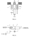
- treating unit 12 comprises a premixed burner 31 located, for example, at one (the bottom) end of reaction chamber 20, and configured for performing controlled combustion in two steps in respective stages 32, 33 of burner 31 :
- Inlet line 15 feeds the vent gas stream for treatment to first stage 32 of burner 31; and secondary-air circuit 17 feeds secondary air to second stage 33 of burner 31, where methane and hydrogen combustion is completed.
- Steam may also be injected optionally into first stage 32 by a steam line 34.
- heat recovery circuit 18 recovers heat from the gases burnt in reaction chamber 20, before they are released into the atmosphere by outlet line 16.
- Heat recovery circuit 18 comprises, for example, a heat exchanger 28 housed inside reaction chamber 20 to draw heat from the gases burnt by burner 31, and produce steam in a boiler 29 and/or preheat air for finishing sections 8, and in particular for the granulating or prilling unit of urea plant 1.
- heat from the gases burnt in reaction chamber 20 may be recovered directly, without going through a heat exchanger, to preheat air for finishing sections 8, and in particular for the granulating or prilling unit of urea plant 1.
- the burnt gases from burner 31 are diluted (i.e. mixed directly, without passing through a heat exchanger) with air for use as atomizing air in the granulating unit, or as fluidizing air in the prilling unit of urea plant 1, for the purpose of raising the air temperature.
- Outlet line 16 therefore connects to an air feed line of the granulating or prilling unit.
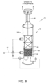
- removal system 10 comprises : a treating unit 12 with a reaction chamber 20; an inlet line 15 connecting treating unit 12 to urea plant 1 (more specifically, to medium-pressure section 6) and supplying treating unit 12 with the gas stream for treatment; and an outlet line 16 for venting, e.g. into the atmosphere, the gas treated by treating unit 12.
- Treating unit 12 comprises a reaction chamber 20 where controlled combustion of the gas stream for treatment is performed. Treating unit 12 is configured to perform catalytic combustion of ammonia in the gas stream for treatment, with an understoichiometric amount of oxygen.
- this embodiment only performs the first step in the process described with reference to the first embodiment in Figure 2 .
- System 10 comprises an integrated unit 35 comprising a heat exchanger 36, e.g. a plate exchanger, and a catalytic cartridge 37 containing the catalyst (e.g. 'ammonia SCO' catalyst) for the first step described above.
- the catalyst eliminates ammonia and possibly also part of the hydrogen (to promote reactions (1), (5) and (6) indicated above, and impede the others) by understoichiometric combustion in a reducing atmosphere, and impedes the formation of nitric oxides.
- the gas stream for treatment flows along inlet line 15 into unit 35, and through heat exchanger 36 to catalytic cartridge 37 in reaction chamber 20, where controlled combustion as described above takes place.
- the hot reacted gas from catalytic cartridge 37 flow through heat exchanger 36 to preheat the gas stream for treatment.
- This embodiment does not include secondary-air supply and, therefore, the second combustion-oxidation step described above.
- the oxygen in the treated gas stream is sufficient to completely oxidize the ammonia.
Landscapes
- Chemical & Material Sciences (AREA)
- Engineering & Computer Science (AREA)
- Environmental & Geological Engineering (AREA)
- Analytical Chemistry (AREA)
- Biomedical Technology (AREA)
- Health & Medical Sciences (AREA)
- General Chemical & Material Sciences (AREA)
- Oil, Petroleum & Natural Gas (AREA)
- Chemical Kinetics & Catalysis (AREA)
- Organic Chemistry (AREA)
- Organic Low-Molecular-Weight Compounds And Preparation Thereof (AREA)
- Treating Waste Gases (AREA)
- Exhaust Gas After Treatment (AREA)
Description
- The present invention relates to a method for removing ammonia from a continuous vent gas stream of a urea (i.e. urea production) plant.
- More specifically, the invention relates to a method for removing small amounts of ammonia from a continuous vent gas stream of a medium-pressure section of a urea plant.
- As is known, urea is produced industrially using processes based on the high-temperature, high-pressure reaction of carbon dioxide and ammonia to form ammonium carbamate, and on the subsequent decomposition reaction of the ammonium carbamate to form urea and water.
- In a typical urea (production) plant, these processes are normally conducted in a synthesis section comprising a urea synthesis reactor; and the urea and water solution produced in the synthesis section is then concentrated gradually - the unconverted reactants being recovered in one or more recovery sections - and is solidified in follow-up finishing (e.g. prilling, granulating, ...) sections.
- In one known configuration, the reactants, which are recirculated to the synthesis section, are recovered in a number of sections, and more specifically in a high-pressure, medium-pressure, and low-pressure section.
- A urea production plant normally produces gas streams containing unconverted reactants, including non-reacted ammonia, and so produces vent gases containing ammonia.
- More specifically, the medium-pressure section vents continuous gas streams containing small amounts of ammonia and hydrogen, as well as methane and inerts (mainly nitrogen). Depending on the process used in the urea production plant, these gas streams may also contain oxygen.
- The gas streams are normally mixed to conform with safety regulations, and more specifically to remain outside explosion limits.
- The ammonia in the gas streams produced in the urea plant, particularly the medium-pressure section, must therefore be removed before releasing the gas streams into the atmosphere.
- One fairly commonly used system for preventing ammonia emission into the atmosphere employs a torch, into which the gases (ammonia, methane, oxygen, hydrogen and inerts) from the medium-pressure section (or urea plant in general) are fed continuously. The gases are fed to the end of the torch, where a gas- (e.g. methane-) fuelled flame burns the ammonia in uncontrolled manner.
- Patent Application
WO2012134288 describes a system based on the use of an incinerator, where a gas stream, rich in ammonia and hydrogen and coming from a urea production process not requiring passivating oxygen, is burned, producing a small amount of NOx; and the ammonia content is further removed, if necessary, using selective catalytic reduction (SCR) or selective non-catalytic reduction (SNCR) processes. -
EP 2 505 581 describes a method of removing ammonia from a vent gas of a urea production plant, the vent gas being subjected to combustion. - Known systems have various drawbacks, and in particular :
- the formation of large amounts of nitric oxide (NOx), in the case of uncontrolled ammonia combustion, with the risk of emitting NOx into the atmosphere;
- relatively high cost, due to the continuous fuel (e.g. methane) supply necessary to keep the torch alight, and to the SCR catalyst for removing the nitric oxides produced;
- the complexity of the process as a whole, operating with no passivating oxygen and with the need for an incinerator.
- It is an object of the present invention to provide a method for removing ammonia from a continuous vent gas stream of a urea plant, in particular of a medium-pressure section of a urea plant, and which provide for reducing, and preferably eliminating, ammonia emissions from a urea production plant relatively cheaply and easily.
- The present invention therefore relates to a method as defined in claim 1.
- Additional preferred characteristics of the invention are indicated in dependent claim 2.
- The invention is intended to remove ammonia from oxygen-containing continuous vent gas streams from the urea production plant, wherein the urea production processes employ passivating oxygen, i.e. processes in which oxygen is added to the synthesis reactor supply to passivate metal (typically, stainless steel) surfaces.
- Mainly due to the intermediate formation of ammonium carbamate, the carbon dioxide-ammonia reaction, in fact, produces highly corrosive conditions capable of even corroding stainless steel normally used in these applications. Adding small amounts of oxygen provides for passivating and so preventing corrosion of the stainless steel surfaces.
- Examples of urea production plants employing oxygen can be found in
WO2010/006757 andWO2008/141832 . - In processes of this type, the vent gas streams for treatment (which are normally pre-mixed to remain below explosion limits) therefore substantially contain : ammonia, hydrogen, methane, inerts (mainly nitrogen), and even a significant percentage of oxygen (though still below explosion limits).
- The vent gas stream from a urea plant (in particular, the medium-pressure section) typically has the following composition (percentages in volume, 1200 Nm3/h at 50°C, 0.1 MPa(g)) :
- NH3 1.3%
- H2 12.0%
- N2 59.7%
- O2 14.8%
- Ar 1.8%
- CH4 10.4%
- In accordance with the invention, the passivating oxygen already present in the urea plant is exploited to remove ammonia.
- Ammonia is removed in at least two combustion stages preferably (though not necessarily) performed in one combustion environment.
- The combustion reaction is therefore performed in controlled manner in two steps or stages :
- a first oxygen-poor (lean) combustion step performed in the presence of an understoichiometric (i.e. less than stoichiometric) amount of oxygen and in a hydrogen-containing reducing atmosphere (reducing atmosphere of hydrogen); at this first step, an understoichiometric amount of the oxygen in the gas stream for treatment is used as the sole comburent (combustion supporter); and the hydrogen (acting as fuel) is also that already present in the gas stream for treatment, and serves to eliminate the few nitric oxides (NOx) that may be formed;
- a second step performed in the presence of a stoichiometric or even greater amount of oxygen, to burn all the remaining gases (in particular, methane and hydrogen); this second step is performed with the addition of secondary air or oxygen to complete combustion of the unburned gases (mainly hydrogen and methane) in the gases from the first step.
- Combustion in accordance with the invention is defined as controlled, in that dividing combustion into steps as described above controls the formation and elimination of nitric oxides (NOx), by means of understoichiometric combustion and the presence of hydrogen respectively, and so reduces nitric oxide emission into the atmosphere.
- The reactions occurring during the combustion process are as follows :
- 1. (1) 4NH3 + 302 → 2N2 + 6H2O (favoured)
- 2. (2) 2NH3 + 202 → N2O + 3H2O (unfavoured)
- 3. (3) 4NH3 + 502 → 4NO + 6H2O (unfavoured)
- 4. (4) 2NO + O2 → 2NO2 (unfavoured)
- 5. (5) NO + H2 → N2 + H2O (favoured)
- 6. (6) 2NO2 + H2 → N2 + 2H2O (favoured)
- Controlled combustion in accordance with the invention does not actually need two combustion chambers. The two steps may be performed in one combustion environment, or in separate combustion chambers.
- The invention is implemented by a catalytic controlled combustion in two sections, with understoichiometric oxygen in the first section, and stoichiometric or overstoichiometric oxygen in the second section.
- More specifically, the two combustion steps are performed by means of respective catalytic oxidations with no flame, and using appropriate respective catalysts. To initiate the catalytic reactions, only a small amount of heat, supplied for example by a heating resistor (with no flame needed), is required at the start of the process (to reach a predetermined activation temperature of about 150°C). During steady, normal operation, on the other hand, no further heat or additional fuel is needed (as stated, the fuel needed is already present in the gas stream for treatment); and secondary air is only supplied at the second step, to sustain the reaction of the second catalyst.
- The first step employs catalysts (one or more) that promote understoichiometric catalytic oxidation of ammonia in a reducing atmosphere, and favour reaction (1) above over the others, particularly those forming nitric oxides, at temperatures ranging roughly between 150°C and 400°C.
- Examples of specific ammonia oxidation catalysts are those in the 'ammonia SCO' (ammonia Selective Catalytic Oxidation) class used for selective ammonia catalytic oxidation, and which are usable in this case, seeing as the continuous gas streams treated already contain the oxygen needed to burn the ammonia, and catalytic reactions (5) and (6) above are strongly favoured by the hydrogen already present in the gas streams, and which reduces the formation of nitric oxides (NOx) and eliminates the few formed.
- Once the ammonia is removed, methane and hydrogen can be removed with a second catalytic oxidation. Because ammonia has been eliminated by the previous ammonia and hydrogen catalytic oxidation reactions, nitric oxide formation in the second oxidation is limited. Catalytic methane combustion acts at a temperature of roughly 500°C to 600-700°C (the heat needed to initiate catalytic methane combustion is generated by the previous oxidation reaction and by catalytic oxidation of hydrogen).
- Before the gases, cleansed of ammonia, methane and hydrogen, are released into the atmosphere, part of the heat produced in the two catalytic beds may be recovered to produce steam or to preheat air for supply to the finishing unit (e.g. granulating or prilling unit, where the urea produced is formed into granules or prills) of the urea production plant.
- Herein disclosed are embodiments which are not encompassed by the wording of the claims. An embodiment (B) not according to the claimed invention employs a premixed burner for controlled combustion in two steps or stages :
- a first step or stage, in which lean combustion is performed in the presence of oxygen and hydrogen already present in the gas stream for treatment; and
- a second step or stage, in which secondary air is injected.
- Lean combustion favours reaction (1) and impedes reactions (2) and (3) above (i.e. favours oxidation of ammonia to nitrogen, and impedes and strongly reduces the formation of nitric oxides).
- Ammonia is oxidized at the first step, which employs the oxygen already present in the continuous gas streams from the urea production plant, thus enabling lean combustion (i.e., in the presence of understoichiometric oxygen, unlike the conventional torch system, in which combustion is performed in an excess of oxygen).
- At the first stage, it is mainly the presence of hydrogen which favours the destruction-elimination of any nitric oxides formed, thus favouring reactions (5) and (6) above.
- Understoichiometric combustion enables a reduction in flame temperature with respect to overstoichiometric combustion (as in a torch), thus further reducing the formation of NOx.
- To further reduce the formation of nitric oxides, steam may be injected at the first oxidation step. Injecting steam further reduces the flame temperature, to impede the formation of nitric oxides.
- Methane and hydrogen combustion is completed at the second stage, in which secondary air or oxygen is supplied.
- Part of the combustion-generated heat may be recovered in a boiler for producing steam. Once the heat is recovered, the clean gases may be released into the atmosphere.
- As opposed to recovering heat in a boiler, all the heat generated in the premixed burner by combustion-oxidation may be recovered to heat the atomizing air for the granulating unit, or the fluidizing air for use in the urea plant prilling unit fluid beds (normally at a temperature of about 135°C), thus reducing cost by eliminating the need for a special steam air preheater.
- In another embodiment (C) not according to the claimed invention, particularly suitable for 'revamping' existing plants equipped with torches, the vent gas stream for treatment, as opposed to being fed to the torch, is diverted to an integrated unit comprising a heat exchanger, e.g. plate type exchanger, and a catalytic cartridge containing the first-step (e.g. 'ammonia SCO') catalyst. As stated, the catalyst provides for eliminating solely ammonia by understoichiometric combustion in a reducing atmosphere, and impeding the formation of nitric oxides.
- This embodiment does not include secondary-air supply and, therefore, the second combustion-oxidation step, in that the oxygen contained in the continuous gas streams from the urea plant is sufficient to completely oxidize the ammonia at the first (and only) step.
- This solution is extremely cheap and compact, not least of all by requiring no additional secondary combustion air lines and equipment (e.g. boilers and fans), and is therefore particularly suitable for 'revamping' existing plants, in which the existing torch is replaced with a new integrated unit.
- A number of non-limiting embodiments of the present invention will be described by way of example with reference to the attached drawings, in which :
-
Figure 1 shows a highly schematic, simplified block diagram of a urea production plant equipped with an ammonia removal system in accordance with the invention; -
Figure 2 shows a schematic of an embodiment of the ammonia removal system according to the invention; -
Figure 3 shows a schematic of an embodiment of an ammonia removal system not according to the invention; -
Figure 4 shows a larger-scale schematic of a detail of theFigure 3 ammonia removal system; -
Figure 5 shows a schematic of a variation of theFigure 3 embodiment not according to the invention; -
Figure 6 shows a schematic of another embodiment of an ammonia removal system not according to the invention. -
Figure 1 shows a highly schematic, simplified block diagram of a urea (production) plant 1. - Urea plant 1, for example, is of the type described in
WO2010/00675 WO2008/141832 . - Urea plant 1 substantially comprises : a synthesis section 2 with a urea synthesis reactor 3 where the urea synthesis reaction from ammonia and carbon dioxide takes place; recovery sections 4 - more specifically, a high-
pressure section 5, medium-pressure section 6, and low-pressure section 7 - where the urea solution from synthesis section 2 is gradually concentrated, non-reacted ammonia and carbon dioxide are removed, and the recovered components are recirculated; and finishingsections 8 including at least one finishing unit, e.g. a granulating or prilling unit where the urea produced is formed into granules or prills. - For the sake of simplicity, the component parts of each section and the lines supplying and recirculating the various gas streams from one section to another are not shown in detail in
Figure 1 , which simply shows schematically the reactant feed lines to urea plant 1, and the operating connections between the sections. - Urea plant 1 is equipped with an
ammonia removal system 10 for processing ammonia-containing vent gas steams produced in urea plant 1. -
System 10 is connected to urea plant 1, e.g. to medium-pressure section 6 (or optionally to other sections), to tap a continuous vent gas stream. - A typical continuous vent gas stream from medium-pressure section 6 of urea plant 1 contains ammonia, hydrogen, methane and inerts (mainly nitrogen).
- According to the present invention, urea plant 1 implements a process employing passivating oxygen supplied to urea plant 1 by an air or
oxygen feed line 11, and therefore the vent gas streams also contain oxygen. - The vent gas stream fed to
system 10 is of such a composition - possibly adjusted by mixing the various component streams - as to be outside explosion limits. - In the
Figure 2 embodiment (A),system 10 comprises a treatingunit 12 having a first andsecond oxidation section inlet line 15 connecting treatingunit 12 to urea plant 1 (more specifically, to medium-pressure section 6) and supplying treatingunit 12 with the gas stream for treatment; anoutlet line 16 for venting, e.g. into the atmosphere, the gas treated by treatingunit 12; a secondary-air circuit 17 for feeding air to treatingunit 12; and aheat recovery circuit 18 for recovering heat from treatingunit 12. - Treating
unit 12 comprises a reaction chamber 20 (defined by one or by two connected chambers) where controlled combustion of the gas stream for treatment is performed. Treatingunit 12 is configured for performing a catalytic controlled combustion of the ammonia contained in the gas stream for treatment. Controlled combustion is performed in two steps, inoxidation sections first section 13, and stoichiometric of overstoichiometric oxygen in thesecond section 14. - More specifically,
sections catalytic beds reaction chamber 20. - Generally, the gas stream flows into
reaction chamber 20 from a central inlet, is fed by afeed pipe 23 to one end ofreaction chamber 20, pastfirst oxidation section 13 and itscatalytic bed 21, and then flows successively throughfirst oxidation section 13 and second oxidation section 14 (and respectivecatalytic beds 21, 22). - As shown by way of example in
Figure 2 ,oxidation sections catalytic beds vertical reaction chamber 20. It is understood, however, thatsections catalytic beds horizontal reaction chamber 20. The gas stream for treatment is fed byfeed pipe 23 to the bottom (or at any rate to one end) ofreaction chamber 20, and then flows first throughfirst oxidation section 13, and then through second oxidation section 14 (and respectivecatalytic beds 21, 22). - The gas stream for treatment is preheated by the gases from
second oxidation section 14 in aheat exchanger 25 located past second oxidation section 14 (abovesecond oxidation section 14 in theFigure 2 example with a vertical reaction chamber 20). -
Catalytic beds - No external fuel need be added, since the fuel used is present in the gas stream for treatment.
- In
first oxidation section 13 there are catalysts (one or more) that promote understoichiometric catalytic oxidation of ammonia in a reducing atmosphere, and possibly also oxidation of part of the hydrogen. - Secondary air is fed into
second section 14 by secondary-air circuit 17. The secondary air is preheated by the gases fromsecond oxidation section 14 in aheat exchanger 26 at the outlet ofsecond oxidation section 14, and is fed past (below, in the case of a vertical reaction chamber 20)catalytic bed 22 ofsecond oxidation section 14 by anair pipe 27 throughcatalytic bed 22. - Catalytic oxidation to remove methane and hydrogen takes place in
second oxidation section 14. -
Heat recovery circuit 18 serves to recover heat from the ammonia-, methane- and hydrogen-free gases produced bycatalytic beds outlet line 16.Heat recovery circuit 18 comprises, for example, aheat exchanger 28 in series withcatalytic beds boiler 29. - Heat from the gases from
oxidation sections sections 8, and in particular for the granulating or prilling unit of urea plant 1. - For example, the gases from
oxidation sections catalytic beds 21, 22), may be diluted (i.e. mixed directly, without passing through a heat exchanger) with air for use as atomizing air in the granulating unit, or as fluidizing air in the prilling unit of urea plant 1, for the purpose of raising the air temperature. - In the
Figure 3 embodiment (B), which is not encompassed by the wording of the claims, in which details similar or identical to those already described are indicated using the same reference numbers,removal system 10 comprises : a treatingunit 12 with areaction chamber 20; aninlet line 15 connecting treatingunit 12 to urea plant 1 (more specifically, to medium-pressure section 6) and supplying treatingunit 12 with the gas stream for treatment; anoutlet line 16 for venting, e.g. into the atmosphere, the gas treated by treatingunit 12; a secondary-air circuit 17 for feeding air to treatingunit 12; and aheat recovery circuit 18 for recovering heat from treatingunit 12. - In this embodiment, too, treating
unit 12 comprises areaction chamber 20 where controlled combustion of the gas stream for treatment is performed, but, in this case, treatingunit 12 is configured for non-catalytic combustion. - More specifically, and with reference also to
Figure 4 , treatingunit 12 comprises a premixedburner 31 located, for example, at one (the bottom) end ofreaction chamber 20, and configured for performing controlled combustion in two steps inrespective stages - a first lean combustion step (first stage 32) in the presence of hydrogen and understoichiometric oxygen already present in the gas stream for treatment;
- a second step (second stage 33) in which secondary air is injected by secondary-
air circuit 17, so combustion takes place in the presence of a stoichiometric or overstoichiometric amount of oxygen. -
Inlet line 15 feeds the vent gas stream for treatment tofirst stage 32 ofburner 31; and secondary-air circuit 17 feeds secondary air tosecond stage 33 ofburner 31, where methane and hydrogen combustion is completed. - Steam may also be injected optionally into
first stage 32 by asteam line 34. - In this embodiment, too,
heat recovery circuit 18 recovers heat from the gases burnt inreaction chamber 20, before they are released into the atmosphere byoutlet line 16.Heat recovery circuit 18 comprises, for example, aheat exchanger 28 housed insidereaction chamber 20 to draw heat from the gases burnt byburner 31, and produce steam in aboiler 29 and/or preheat air for finishingsections 8, and in particular for the granulating or prilling unit of urea plant 1. - Alternatively, heat from the gases burnt in
reaction chamber 20 may be recovered directly, without going through a heat exchanger, to preheat air for finishingsections 8, and in particular for the granulating or prilling unit of urea plant 1. - For example, as shown in
Figure 5 , the burnt gases fromburner 31 are diluted (i.e. mixed directly, without passing through a heat exchanger) with air for use as atomizing air in the granulating unit, or as fluidizing air in the prilling unit of urea plant 1, for the purpose of raising the air temperature.Outlet line 16 therefore connects to an air feed line of the granulating or prilling unit. - In the
Figure 6 embodiment (C), which is not encompassed by the wording of the claims, in which details similar or identical to those already described are indicated using the same reference numbers,removal system 10 comprises : a treatingunit 12 with areaction chamber 20; aninlet line 15 connecting treatingunit 12 to urea plant 1 (more specifically, to medium-pressure section 6) and supplying treatingunit 12 with the gas stream for treatment; and anoutlet line 16 for venting, e.g. into the atmosphere, the gas treated by treatingunit 12. - Treating
unit 12 comprises areaction chamber 20 where controlled combustion of the gas stream for treatment is performed. Treatingunit 12 is configured to perform catalytic combustion of ammonia in the gas stream for treatment, with an understoichiometric amount of oxygen. - In other words, this embodiment only performs the first step in the process described with reference to the first embodiment in
Figure 2 . -
System 10 comprises anintegrated unit 35 comprising aheat exchanger 36, e.g. a plate exchanger, and acatalytic cartridge 37 containing the catalyst (e.g. 'ammonia SCO' catalyst) for the first step described above. The catalyst eliminates ammonia and possibly also part of the hydrogen (to promote reactions (1), (5) and (6) indicated above, and impede the others) by understoichiometric combustion in a reducing atmosphere, and impedes the formation of nitric oxides. - The gas stream for treatment flows along
inlet line 15 intounit 35, and throughheat exchanger 36 tocatalytic cartridge 37 inreaction chamber 20, where controlled combustion as described above takes place. The hot reacted gas fromcatalytic cartridge 37 flow throughheat exchanger 36 to preheat the gas stream for treatment. - This embodiment does not include secondary-air supply and, therefore, the second combustion-oxidation step described above. The oxygen in the treated gas stream is sufficient to completely oxidize the ammonia.
- Clearly, further changes may be made to the method and system as described herein without, however, departing from the scope of the accompanying claims.
Claims (2)
- A method of removing ammonia from a continuous vent gas stream of a urea plant (1), in particular of a medium-pressure section (6) of a urea plant, the method comprising a step of removing ammonia from the continuous vent gas stream of the urea plant (1) by means of a controlled-combustion process comprising at least a first lean, oxygen-poor combustion step performed in the presence of an understoichiometric amount of oxygen acting as the sole comburent, and in a hydrogen-containing reducing atmosphere so as to favour oxidation of ammonia to nitrogen and impede and strongly reduce the formation of nitric oxides, and in which ammonia is oxidized; wherein the continuous vent gas stream for treatment contains passivating oxygen, and the passivating oxygen used in the urea plant (1) and already present in the continuous vent gas stream for treatment is exploited to remove ammonia in said first combustion step: and wherein, in addition to said first lean combustion step, the controlled-combustion process comprises a second combustion step performed in the presence of a stoichiometric or even greater amount of oxygen, to burn the gases remaining from the first combustion step, and in particular methane and hydrogen; said second combustion step being performed with the addition of secondary air or oxygen to complete combustion of the unburned gases in the gases from the first combustion step; and wherein said first and second combustion steps are two catalytic oxidation steps performed in respective oxidation sections (13, 14), with understoichiometric oxygen in the first oxidation section (13), and stoichiometric or overstoichiometric oxygen in the second oxidation section (14).
- A method according to claim 1, and comprising a step of recovering heat from the gases cleansed of ammonia, methane and hydrogen, before they are released into the atmosphere, to produce steam and/or pre-heat air for supply to a finishing unit, in particular a granulating or prilling unit, of the urea plant.
Applications Claiming Priority (2)
| Application Number | Priority Date | Filing Date | Title |
|---|---|---|---|
| IT000268A ITMI20130268A1 (en) | 2013-02-25 | 2013-02-25 | METHOD AND SYSTEM FOR THE KILLING OF AMMONIA FROM A GASEOUS FLOW OF DISCHARGE OF A UREA PLANT |
| PCT/IB2014/059242 WO2014128682A1 (en) | 2013-02-25 | 2014-02-25 | Method and system for removing ammonia from a vent gas stream of a urea plant |
Publications (3)
| Publication Number | Publication Date |
|---|---|
| EP2958659A1 EP2958659A1 (en) | 2015-12-30 |
| EP2958659B1 EP2958659B1 (en) | 2017-04-05 |
| EP2958659B2 true EP2958659B2 (en) | 2023-11-22 |
Family
ID=48184316
Family Applications (1)
| Application Number | Title | Priority Date | Filing Date |
|---|---|---|---|
| EP14716000.6A Active EP2958659B2 (en) | 2013-02-25 | 2014-02-25 | Method for removing ammonia from a vent gas stream of a urea plant |
Country Status (9)
| Country | Link |
|---|---|
| US (1) | US10434468B2 (en) |
| EP (1) | EP2958659B2 (en) |
| AR (1) | AR094880A1 (en) |
| CA (1) | CA2900434C (en) |
| ES (1) | ES2624663T5 (en) |
| IT (1) | ITMI20130268A1 (en) |
| PL (1) | PL2958659T5 (en) |
| RU (1) | RU2650153C2 (en) |
| WO (1) | WO2014128682A1 (en) |
Families Citing this family (3)
| Publication number | Priority date | Publication date | Assignee | Title |
|---|---|---|---|---|
| BR112020009599B1 (en) * | 2017-11-16 | 2023-12-05 | Casale Sa | Method and system for measuring a liquid level in a pressure vessel of a urea synthesis plant |
| US11458436B2 (en) | 2019-08-28 | 2022-10-04 | Stephen R. Temple | Methods for absorbing a targeted compound from a gas stream for subsequent processing or use |
| US12403421B2 (en) | 2021-12-31 | 2025-09-02 | Stephen R. Temple | Methods for absorbing a targeted compound from a gas stream for subsequent processing or use |
Citations (5)
| Publication number | Priority date | Publication date | Assignee | Title |
|---|---|---|---|---|
| DE3308406A1 (en) † | 1982-03-11 | 1983-09-15 | Shell Internationale Research Maatschappij B.V., 2501 Den Haag | METHOD AND DEVICE FOR COMBUSTION OF AMMONIA-CONTAINING EXHAUST GASES |
| DE4116362A1 (en) † | 1991-05-18 | 1992-11-19 | Solvay Catalysts Gmbh | METHOD FOR REMOVING THE AMMONIA CONTENT IN GASES |
| EP1106239A2 (en) † | 1999-12-10 | 2001-06-13 | The BOC Group plc | Method for purifying waste gas containing ammonia |
| US20110158875A1 (en) † | 2005-09-14 | 2011-06-30 | Nalette Timothy A | Selective catalytic oxidation of ammonia to water and nitrogen |
| EP2505581A1 (en) † | 2011-03-31 | 2012-10-03 | Stamicarbon B.V. | Zero emission urea process and plant |
Family Cites Families (9)
| Publication number | Priority date | Publication date | Assignee | Title |
|---|---|---|---|---|
| US2046827A (en) * | 1933-08-09 | 1936-07-07 | Atmospheric Nitrogen Corp | Production of urea and nitrogen oxides |
| US3522305A (en) * | 1966-08-01 | 1970-07-28 | Marathon Oil Co | Production of urea and derivatives of ethylene and acetylene |
| US4330513A (en) * | 1976-10-13 | 1982-05-18 | Air Resources, Inc. | Catalytic fume incineration |
| US5934892A (en) * | 1998-08-06 | 1999-08-10 | Institute Of Gas Technology | Process and apparatus for emissions reduction using partial oxidation of combustible material |
| ITMI20071029A1 (en) | 2007-05-22 | 2008-11-23 | Snam Progetti | IMPROVED PROCEDURE FOR THE SYNTHESIS OF UREA |
| US7695701B2 (en) | 2008-03-07 | 2010-04-13 | Du Pont | Process for treating acid gas in staged furnaces with inter-stage heat recovery |
| IT1391426B1 (en) | 2008-07-17 | 2011-12-23 | Snam Progetti | TUBE BAND EQUIPMENT FOR PROCESSING CORROSIVE FLUIDS |
| IT1396917B1 (en) * | 2009-10-23 | 2012-12-20 | Sini S P A Gia Siirtec Nigi S P A | PROCESS FOR RECOVERY OF SULFUR FROM GAS CURRENCIES RICH IN AMMONIA, FROM CURRENTS OF GAS ACIDS AND SULFUR DIOXIDE |
| IT1397745B1 (en) * | 2010-01-22 | 2013-01-24 | Siirtec Nigi S P A | INTEGRATED PROCESS OF PURIFICATION OF REFINERY WATERS, CONTAINING PRECISELY AMMONIA AND SULFIDRIC ACID, AND OF GAS ACIDS CONTAINING PREVIOUSLY SULFIDRIC ACID. |
-
2013
- 2013-02-25 IT IT000268A patent/ITMI20130268A1/en unknown
-
2014
- 2014-02-25 US US14/768,404 patent/US10434468B2/en active Active
- 2014-02-25 EP EP14716000.6A patent/EP2958659B2/en active Active
- 2014-02-25 AR ARP140100585A patent/AR094880A1/en active IP Right Grant
- 2014-02-25 PL PL14716000.6T patent/PL2958659T5/en unknown
- 2014-02-25 RU RU2015140754A patent/RU2650153C2/en active
- 2014-02-25 WO PCT/IB2014/059242 patent/WO2014128682A1/en not_active Ceased
- 2014-02-25 ES ES14716000T patent/ES2624663T5/en active Active
- 2014-02-25 CA CA2900434A patent/CA2900434C/en active Active
Patent Citations (5)
| Publication number | Priority date | Publication date | Assignee | Title |
|---|---|---|---|---|
| DE3308406A1 (en) † | 1982-03-11 | 1983-09-15 | Shell Internationale Research Maatschappij B.V., 2501 Den Haag | METHOD AND DEVICE FOR COMBUSTION OF AMMONIA-CONTAINING EXHAUST GASES |
| DE4116362A1 (en) † | 1991-05-18 | 1992-11-19 | Solvay Catalysts Gmbh | METHOD FOR REMOVING THE AMMONIA CONTENT IN GASES |
| EP1106239A2 (en) † | 1999-12-10 | 2001-06-13 | The BOC Group plc | Method for purifying waste gas containing ammonia |
| US20110158875A1 (en) † | 2005-09-14 | 2011-06-30 | Nalette Timothy A | Selective catalytic oxidation of ammonia to water and nitrogen |
| EP2505581A1 (en) † | 2011-03-31 | 2012-10-03 | Stamicarbon B.V. | Zero emission urea process and plant |
Non-Patent Citations (3)
| Title |
|---|
| JOEY DOBREE: "From flaring to environmental friendly ammonia firing and that even done in an economical way", 25TH AFA INTERNATIONAL FERTILIZER TECHNOLOGY CONFERENCE & EXHIBITION, 9 July 2012 (2012-07-09), Dubai , UAE, pages 1 - 26 † |
| KLAUS STEINEBRUNNER ET AL.: "Verbrennung NH3-haltiger Prozessgase", CHEM.-ING.-TECH., vol. 67, no. 2, February 1995 (1995-02-01), pages 199 - 202 † |
| UNITED STATES ENVIRONMENTAL PROTECTION AGENCY (EPA): "Nitrogen Oxides (NOx), Why and How They Are Controlled", EPA TECHNICAL BULLETIN /EPA 456/F-99-006R/, November 1999 (1999-11-01), pages ii-viii, 1 - 48 † |
Also Published As
| Publication number | Publication date |
|---|---|
| EP2958659A1 (en) | 2015-12-30 |
| US20160001224A1 (en) | 2016-01-07 |
| CA2900434C (en) | 2021-06-22 |
| PL2958659T5 (en) | 2025-11-17 |
| AR094880A1 (en) | 2015-09-02 |
| WO2014128682A1 (en) | 2014-08-28 |
| US10434468B2 (en) | 2019-10-08 |
| ES2624663T5 (en) | 2024-05-21 |
| RU2650153C2 (en) | 2018-04-09 |
| EP2958659B1 (en) | 2017-04-05 |
| CA2900434A1 (en) | 2014-08-28 |
| PL2958659T3 (en) | 2017-09-29 |
| RU2015140754A (en) | 2017-03-30 |
| ITMI20130268A1 (en) | 2014-08-26 |
| ES2624663T3 (en) | 2017-07-17 |
Similar Documents
| Publication | Publication Date | Title |
|---|---|---|
| EP3962859B1 (en) | Revamping of a claus plant with a sulfuric acid plan | |
| CN102985166B (en) | Method and device for removing NOx and N2O | |
| CN112403258B (en) | System and method for removing carbon monoxide and denitration of flue gas | |
| EP3515861B1 (en) | Plant and process for producing nitric acid | |
| EP1975381B1 (en) | Method of denitrification of exhaust gas and apparatus therefor | |
| CN108295652B (en) | Integrated process and system for flue gas desulfurization and denitration waste heat utilization of carbon rotary kiln | |
| CN101356344B (en) | Exhaust gas denitrification method and device | |
| EP2958659B2 (en) | Method for removing ammonia from a vent gas stream of a urea plant | |
| JP2004513322A (en) | Burner and partial oxidation process for gas streams containing hydrogen sulfide and ammonia | |
| CN103443070B (en) | Zero discharge urea method and apparatus | |
| JP2017520546A (en) | Method and apparatus for removing nitrogen oxides from exhaust gas by nitration | |
| US7648673B2 (en) | Process for denoxification of off-gases from annealing and pickling lines, and an annealing and pickling line, especially for stainless steel hot or cold strip | |
| KR102607313B1 (en) | Method and system for removing hazardous compounds from flue gas using SCR catalyst | |
| JP7041745B2 (en) | Method for producing sulfur and sulfuric acid | |
| US11407645B2 (en) | Method and apparatus for producing carbon dioxide | |
| CN112403223A (en) | A system and method for removing carbon monoxide and denitrification from heat-exchange flue gas | |
| EP3285912B1 (en) | Method and system for selective noncatalytic nox reduction | |
| WO2025061566A1 (en) | Conversion of a gas feed into a hydrogen-containing effluent gas, reducing a content of nitrogen oxides in the flue gas | |
| KR102772038B1 (en) | NOx Removal Reactor Using Ammonia Decompostion Gas and Design Method Thereof | |
| KR20210115916A (en) | NOx REMOVING SYSTEM THROUGH OXIDATION, DEOXIDATION AND RETURN OF EXHAUST GAS | |
| CN220582443U (en) | Device for treating nitrogen oxides in tail gas generated by incinerating ethylene glycol MF (methyl) produced by coal |
Legal Events
| Date | Code | Title | Description |
|---|---|---|---|
| PUAI | Public reference made under article 153(3) epc to a published international application that has entered the european phase |
Free format text: ORIGINAL CODE: 0009012 |
|
| 17P | Request for examination filed |
Effective date: 20150806 |
|
| AK | Designated contracting states |
Kind code of ref document: A1 Designated state(s): AL AT BE BG CH CY CZ DE DK EE ES FI FR GB GR HR HU IE IS IT LI LT LU LV MC MK MT NL NO PL PT RO RS SE SI SK SM TR |
|
| AX | Request for extension of the european patent |
Extension state: BA ME |
|
| DAX | Request for extension of the european patent (deleted) | ||
| GRAP | Despatch of communication of intention to grant a patent |
Free format text: ORIGINAL CODE: EPIDOSNIGR1 |
|
| INTG | Intention to grant announced |
Effective date: 20160923 |
|
| STAA | Information on the status of an ep patent application or granted ep patent |
Free format text: STATUS: GRANT OF PATENT IS INTENDED |
|
| GRAS | Grant fee paid |
Free format text: ORIGINAL CODE: EPIDOSNIGR3 |
|
| GRAA | (expected) grant |
Free format text: ORIGINAL CODE: 0009210 |
|
| STAA | Information on the status of an ep patent application or granted ep patent |
Free format text: STATUS: THE PATENT HAS BEEN GRANTED |
|
| AK | Designated contracting states |
Kind code of ref document: B1 Designated state(s): AL AT BE BG CH CY CZ DE DK EE ES FI FR GB GR HR HU IE IS IT LI LT LU LV MC MK MT NL NO PL PT RO RS SE SI SK SM TR |
|
| REG | Reference to a national code |
Ref country code: GB Ref legal event code: FG4D |
|
| REG | Reference to a national code |
Ref country code: CH Ref legal event code: EP |
|
| REG | Reference to a national code |
Ref country code: AT Ref legal event code: REF Ref document number: 881266 Country of ref document: AT Kind code of ref document: T Effective date: 20170415 |
|
| REG | Reference to a national code |
Ref country code: IE Ref legal event code: FG4D |
|
| REG | Reference to a national code |
Ref country code: NL Ref legal event code: FP |
|
| REG | Reference to a national code |
Ref country code: DE Ref legal event code: R096 Ref document number: 602014008342 Country of ref document: DE |
|
| REG | Reference to a national code |
Ref country code: CH Ref legal event code: NV Representative=s name: HEPP WENGER RYFFEL AG, CH |
|
| REG | Reference to a national code |
Ref country code: ES Ref legal event code: FG2A Ref document number: 2624663 Country of ref document: ES Kind code of ref document: T3 Effective date: 20170717 |
|
| REG | Reference to a national code |
Ref country code: LT Ref legal event code: MG4D |
|
| PG25 | Lapsed in a contracting state [announced via postgrant information from national office to epo] |
Ref country code: FI Free format text: LAPSE BECAUSE OF FAILURE TO SUBMIT A TRANSLATION OF THE DESCRIPTION OR TO PAY THE FEE WITHIN THE PRESCRIBED TIME-LIMIT Effective date: 20170405 Ref country code: LT Free format text: LAPSE BECAUSE OF FAILURE TO SUBMIT A TRANSLATION OF THE DESCRIPTION OR TO PAY THE FEE WITHIN THE PRESCRIBED TIME-LIMIT Effective date: 20170405 Ref country code: GR Free format text: LAPSE BECAUSE OF FAILURE TO SUBMIT A TRANSLATION OF THE DESCRIPTION OR TO PAY THE FEE WITHIN THE PRESCRIBED TIME-LIMIT Effective date: 20170706 Ref country code: NO Free format text: LAPSE BECAUSE OF FAILURE TO SUBMIT A TRANSLATION OF THE DESCRIPTION OR TO PAY THE FEE WITHIN THE PRESCRIBED TIME-LIMIT Effective date: 20170705 Ref country code: HR Free format text: LAPSE BECAUSE OF FAILURE TO SUBMIT A TRANSLATION OF THE DESCRIPTION OR TO PAY THE FEE WITHIN THE PRESCRIBED TIME-LIMIT Effective date: 20170405 |
|
| PG25 | Lapsed in a contracting state [announced via postgrant information from national office to epo] |
Ref country code: SE Free format text: LAPSE BECAUSE OF FAILURE TO SUBMIT A TRANSLATION OF THE DESCRIPTION OR TO PAY THE FEE WITHIN THE PRESCRIBED TIME-LIMIT Effective date: 20170405 Ref country code: IS Free format text: LAPSE BECAUSE OF FAILURE TO SUBMIT A TRANSLATION OF THE DESCRIPTION OR TO PAY THE FEE WITHIN THE PRESCRIBED TIME-LIMIT Effective date: 20170805 Ref country code: RS Free format text: LAPSE BECAUSE OF FAILURE TO SUBMIT A TRANSLATION OF THE DESCRIPTION OR TO PAY THE FEE WITHIN THE PRESCRIBED TIME-LIMIT Effective date: 20170405 Ref country code: BG Free format text: LAPSE BECAUSE OF FAILURE TO SUBMIT A TRANSLATION OF THE DESCRIPTION OR TO PAY THE FEE WITHIN THE PRESCRIBED TIME-LIMIT Effective date: 20170705 Ref country code: LV Free format text: LAPSE BECAUSE OF FAILURE TO SUBMIT A TRANSLATION OF THE DESCRIPTION OR TO PAY THE FEE WITHIN THE PRESCRIBED TIME-LIMIT Effective date: 20170405 |
|
| REG | Reference to a national code |
Ref country code: DE Ref legal event code: R026 Ref document number: 602014008342 Country of ref document: DE |
|
| PLBI | Opposition filed |
Free format text: ORIGINAL CODE: 0009260 |
|
| PLBI | Opposition filed |
Free format text: ORIGINAL CODE: 0009260 |
|
| PLAX | Notice of opposition and request to file observation + time limit sent |
Free format text: ORIGINAL CODE: EPIDOSNOBS2 |
|
| PG25 | Lapsed in a contracting state [announced via postgrant information from national office to epo] |
Ref country code: SK Free format text: LAPSE BECAUSE OF FAILURE TO SUBMIT A TRANSLATION OF THE DESCRIPTION OR TO PAY THE FEE WITHIN THE PRESCRIBED TIME-LIMIT Effective date: 20170405 Ref country code: DK Free format text: LAPSE BECAUSE OF FAILURE TO SUBMIT A TRANSLATION OF THE DESCRIPTION OR TO PAY THE FEE WITHIN THE PRESCRIBED TIME-LIMIT Effective date: 20170405 Ref country code: RO Free format text: LAPSE BECAUSE OF FAILURE TO SUBMIT A TRANSLATION OF THE DESCRIPTION OR TO PAY THE FEE WITHIN THE PRESCRIBED TIME-LIMIT Effective date: 20170405 Ref country code: EE Free format text: LAPSE BECAUSE OF FAILURE TO SUBMIT A TRANSLATION OF THE DESCRIPTION OR TO PAY THE FEE WITHIN THE PRESCRIBED TIME-LIMIT Effective date: 20170405 |
|
| 26 | Opposition filed |
Opponent name: THYSSENKRUPP ELEVATOR INNOVATION GMBH/ THYSSENKRUP Effective date: 20171220 |
|
| 26 | Opposition filed |
Opponent name: STAMICARBON B.V. Effective date: 20180104 |
|
| PLAB | Opposition data, opponent's data or that of the opponent's representative modified |
Free format text: ORIGINAL CODE: 0009299OPPO |
|
| REG | Reference to a national code |
Ref country code: FR Ref legal event code: PLFP Year of fee payment: 5 |
|
| PG25 | Lapsed in a contracting state [announced via postgrant information from national office to epo] |
Ref country code: SM Free format text: LAPSE BECAUSE OF FAILURE TO SUBMIT A TRANSLATION OF THE DESCRIPTION OR TO PAY THE FEE WITHIN THE PRESCRIBED TIME-LIMIT Effective date: 20170405 |
|
| R26 | Opposition filed (corrected) |
Opponent name: THYSSENKRUPP INDUSTRIAL SOLUTIONS AG Effective date: 20171220 |
|
| PG25 | Lapsed in a contracting state [announced via postgrant information from national office to epo] |
Ref country code: SI Free format text: LAPSE BECAUSE OF FAILURE TO SUBMIT A TRANSLATION OF THE DESCRIPTION OR TO PAY THE FEE WITHIN THE PRESCRIBED TIME-LIMIT Effective date: 20170405 |
|
| PLBB | Reply of patent proprietor to notice(s) of opposition received |
Free format text: ORIGINAL CODE: EPIDOSNOBS3 |
|
| PLAB | Opposition data, opponent's data or that of the opponent's representative modified |
Free format text: ORIGINAL CODE: 0009299OPPO |
|
| R26 | Opposition filed (corrected) |
Opponent name: THYSSENKRUPP INDUSTRIAL SOLUTIONS AG Effective date: 20171220 |
|
| PG25 | Lapsed in a contracting state [announced via postgrant information from national office to epo] |
Ref country code: MC Free format text: LAPSE BECAUSE OF FAILURE TO SUBMIT A TRANSLATION OF THE DESCRIPTION OR TO PAY THE FEE WITHIN THE PRESCRIBED TIME-LIMIT Effective date: 20170405 |
|
| GBPC | Gb: european patent ceased through non-payment of renewal fee |
Effective date: 20180225 |
|
| REG | Reference to a national code |
Ref country code: IE Ref legal event code: MM4A |
|
| REG | Reference to a national code |
Ref country code: BE Ref legal event code: MM Effective date: 20180228 |
|
| PG25 | Lapsed in a contracting state [announced via postgrant information from national office to epo] |
Ref country code: LU Free format text: LAPSE BECAUSE OF NON-PAYMENT OF DUE FEES Effective date: 20180225 |
|
| PG25 | Lapsed in a contracting state [announced via postgrant information from national office to epo] |
Ref country code: IE Free format text: LAPSE BECAUSE OF NON-PAYMENT OF DUE FEES Effective date: 20180225 |
|
| PG25 | Lapsed in a contracting state [announced via postgrant information from national office to epo] |
Ref country code: GB Free format text: LAPSE BECAUSE OF NON-PAYMENT OF DUE FEES Effective date: 20180225 Ref country code: BE Free format text: LAPSE BECAUSE OF NON-PAYMENT OF DUE FEES Effective date: 20180228 |
|
| APAH | Appeal reference modified |
Free format text: ORIGINAL CODE: EPIDOSCREFNO |
|
| APBM | Appeal reference recorded |
Free format text: ORIGINAL CODE: EPIDOSNREFNO |
|
| APBP | Date of receipt of notice of appeal recorded |
Free format text: ORIGINAL CODE: EPIDOSNNOA2O |
|
| REG | Reference to a national code |
Ref country code: AT Ref legal event code: UEP Ref document number: 881266 Country of ref document: AT Kind code of ref document: T Effective date: 20170405 |
|
| APBQ | Date of receipt of statement of grounds of appeal recorded |
Free format text: ORIGINAL CODE: EPIDOSNNOA3O |
|
| PG25 | Lapsed in a contracting state [announced via postgrant information from national office to epo] |
Ref country code: MT Free format text: LAPSE BECAUSE OF NON-PAYMENT OF DUE FEES Effective date: 20180225 |
|
| PG25 | Lapsed in a contracting state [announced via postgrant information from national office to epo] |
Ref country code: TR Free format text: LAPSE BECAUSE OF FAILURE TO SUBMIT A TRANSLATION OF THE DESCRIPTION OR TO PAY THE FEE WITHIN THE PRESCRIBED TIME-LIMIT Effective date: 20170405 |
|
| PG25 | Lapsed in a contracting state [announced via postgrant information from national office to epo] |
Ref country code: PT Free format text: LAPSE BECAUSE OF FAILURE TO SUBMIT A TRANSLATION OF THE DESCRIPTION OR TO PAY THE FEE WITHIN THE PRESCRIBED TIME-LIMIT Effective date: 20170405 |
|
| PG25 | Lapsed in a contracting state [announced via postgrant information from national office to epo] |
Ref country code: MK Free format text: LAPSE BECAUSE OF NON-PAYMENT OF DUE FEES Effective date: 20170405 Ref country code: HU Free format text: LAPSE BECAUSE OF FAILURE TO SUBMIT A TRANSLATION OF THE DESCRIPTION OR TO PAY THE FEE WITHIN THE PRESCRIBED TIME-LIMIT; INVALID AB INITIO Effective date: 20140225 Ref country code: CY Free format text: LAPSE BECAUSE OF FAILURE TO SUBMIT A TRANSLATION OF THE DESCRIPTION OR TO PAY THE FEE WITHIN THE PRESCRIBED TIME-LIMIT Effective date: 20170405 |
|
| PG25 | Lapsed in a contracting state [announced via postgrant information from national office to epo] |
Ref country code: AL Free format text: LAPSE BECAUSE OF FAILURE TO SUBMIT A TRANSLATION OF THE DESCRIPTION OR TO PAY THE FEE WITHIN THE PRESCRIBED TIME-LIMIT Effective date: 20170405 |
|
| APBU | Appeal procedure closed |
Free format text: ORIGINAL CODE: EPIDOSNNOA9O |
|
| PLAY | Examination report in opposition despatched + time limit |
Free format text: ORIGINAL CODE: EPIDOSNORE2 |
|
| PLBC | Reply to examination report in opposition received |
Free format text: ORIGINAL CODE: EPIDOSNORE3 |
|
| PLAY | Examination report in opposition despatched + time limit |
Free format text: ORIGINAL CODE: EPIDOSNORE2 |
|
| P01 | Opt-out of the competence of the unified patent court (upc) registered |
Effective date: 20230420 |
|
| RAP4 | Party data changed (patent owner data changed or rights of a patent transferred) |
Owner name: SAIPEM S.P.A. |
|
| PUAH | Patent maintained in amended form |
Free format text: ORIGINAL CODE: 0009272 |
|
| STAA | Information on the status of an ep patent application or granted ep patent |
Free format text: STATUS: PATENT MAINTAINED AS AMENDED |
|
| 27A | Patent maintained in amended form |
Effective date: 20231122 |
|
| AK | Designated contracting states |
Kind code of ref document: B2 Designated state(s): AL AT BE BG CH CY CZ DE DK EE ES FI FR GB GR HR HU IE IS IT LI LT LU LV MC MK MT NL NO PL PT RO RS SE SI SK SM TR |
|
| REG | Reference to a national code |
Ref country code: DE Ref legal event code: R102 Ref document number: 602014008342 Country of ref document: DE |
|
| P02 | Opt-out of the competence of the unified patent court (upc) changed |
Effective date: 20231116 |
|
| REG | Reference to a national code |
Ref country code: NL Ref legal event code: FP |
|
| REG | Reference to a national code |
Ref country code: ES Ref legal event code: DC2A Ref document number: 2624663 Country of ref document: ES Kind code of ref document: T5 Effective date: 20240521 |
|
| PGFP | Annual fee paid to national office [announced via postgrant information from national office to epo] |
Ref country code: NL Payment date: 20250224 Year of fee payment: 12 |
|
| PGFP | Annual fee paid to national office [announced via postgrant information from national office to epo] |
Ref country code: DE Payment date: 20250226 Year of fee payment: 12 |
|
| PGFP | Annual fee paid to national office [announced via postgrant information from national office to epo] |
Ref country code: ES Payment date: 20250317 Year of fee payment: 12 |
|
| PGFP | Annual fee paid to national office [announced via postgrant information from national office to epo] |
Ref country code: AT Payment date: 20250217 Year of fee payment: 12 Ref country code: CH Payment date: 20250301 Year of fee payment: 12 |
|
| PGFP | Annual fee paid to national office [announced via postgrant information from national office to epo] |
Ref country code: FR Payment date: 20250224 Year of fee payment: 12 Ref country code: CZ Payment date: 20250217 Year of fee payment: 12 |
|
| PGFP | Annual fee paid to national office [announced via postgrant information from national office to epo] |
Ref country code: IT Payment date: 20250225 Year of fee payment: 12 |
|
| PGFP | Annual fee paid to national office [announced via postgrant information from national office to epo] |
Ref country code: PL Payment date: 20250214 Year of fee payment: 12 |
|
| REG | Reference to a national code |
Ref country code: AT Ref legal event code: UEP Ref document number: 881266 Country of ref document: AT Kind code of ref document: T Effective date: 20231122 |