EP2958204A1 - Arc resistant shutters - Google Patents
Arc resistant shutters Download PDFInfo
- Publication number
- EP2958204A1 EP2958204A1 EP15172360.8A EP15172360A EP2958204A1 EP 2958204 A1 EP2958204 A1 EP 2958204A1 EP 15172360 A EP15172360 A EP 15172360A EP 2958204 A1 EP2958204 A1 EP 2958204A1
- Authority
- EP
- European Patent Office
- Prior art keywords
- bus bar
- shutter
- connector
- circuit breaker
- cluster
- Prior art date
- Legal status (The legal status is an assumption and is not a legal conclusion. Google has not performed a legal analysis and makes no representation as to the accuracy of the status listed.)
- Granted
Links
Images







Classifications
-
- H—ELECTRICITY
- H02—GENERATION; CONVERSION OR DISTRIBUTION OF ELECTRIC POWER
- H02B—BOARDS, SUBSTATIONS OR SWITCHING ARRANGEMENTS FOR THE SUPPLY OR DISTRIBUTION OF ELECTRIC POWER
- H02B1/00—Frameworks, boards, panels, desks, casings; Details of substations or switching arrangements
- H02B1/14—Shutters or guards for preventing access to contacts
-
- H—ELECTRICITY
- H02—GENERATION; CONVERSION OR DISTRIBUTION OF ELECTRIC POWER
- H02B—BOARDS, SUBSTATIONS OR SWITCHING ARRANGEMENTS FOR THE SUPPLY OR DISTRIBUTION OF ELECTRIC POWER
- H02B11/00—Switchgear having carriage withdrawable for isolation
- H02B11/24—Shutters or guards
-
- H—ELECTRICITY
- H01—ELECTRIC ELEMENTS
- H01B—CABLES; CONDUCTORS; INSULATORS; SELECTION OF MATERIALS FOR THEIR CONDUCTIVE, INSULATING OR DIELECTRIC PROPERTIES
- H01B17/00—Insulators or insulating bodies characterised by their form
- H01B17/42—Means for obtaining improved distribution of voltage; Protection against arc discharges
-
- H—ELECTRICITY
- H01—ELECTRIC ELEMENTS
- H01H—ELECTRIC SWITCHES; RELAYS; SELECTORS; EMERGENCY PROTECTIVE DEVICES
- H01H9/00—Details of switching devices, not covered by groups H01H1/00 - H01H7/00
- H01H9/20—Interlocking, locking, or latching mechanisms
- H01H9/22—Interlocking, locking, or latching mechanisms for interlocking between casing, cover, or protective shutter and mechanism for operating contacts
-
- H—ELECTRICITY
- H02—GENERATION; CONVERSION OR DISTRIBUTION OF ELECTRIC POWER
- H02B—BOARDS, SUBSTATIONS OR SWITCHING ARRANGEMENTS FOR THE SUPPLY OR DISTRIBUTION OF ELECTRIC POWER
- H02B1/00—Frameworks, boards, panels, desks, casings; Details of substations or switching arrangements
- H02B1/20—Bus-bar or other wiring layouts, e.g. in cubicles, in switchyards
- H02B1/21—Bus-bar arrangements for rack-mounted devices with withdrawable units
-
- H—ELECTRICITY
- H02—GENERATION; CONVERSION OR DISTRIBUTION OF ELECTRIC POWER
- H02B—BOARDS, SUBSTATIONS OR SWITCHING ARRANGEMENTS FOR THE SUPPLY OR DISTRIBUTION OF ELECTRIC POWER
- H02B1/00—Frameworks, boards, panels, desks, casings; Details of substations or switching arrangements
- H02B1/26—Casings; Parts thereof or accessories therefor
- H02B1/30—Cabinet-type casings; Parts thereof or accessories therefor
-
- H—ELECTRICITY
- H02—GENERATION; CONVERSION OR DISTRIBUTION OF ELECTRIC POWER
- H02B—BOARDS, SUBSTATIONS OR SWITCHING ARRANGEMENTS FOR THE SUPPLY OR DISTRIBUTION OF ELECTRIC POWER
- H02B1/00—Frameworks, boards, panels, desks, casings; Details of substations or switching arrangements
- H02B1/26—Casings; Parts thereof or accessories therefor
- H02B1/30—Cabinet-type casings; Parts thereof or accessories therefor
- H02B1/32—Mounting of devices therein
- H02B1/34—Racks
- H02B1/36—Racks with withdrawable units
-
- H—ELECTRICITY
- H02—GENERATION; CONVERSION OR DISTRIBUTION OF ELECTRIC POWER
- H02B—BOARDS, SUBSTATIONS OR SWITCHING ARRANGEMENTS FOR THE SUPPLY OR DISTRIBUTION OF ELECTRIC POWER
- H02B11/00—Switchgear having carriage withdrawable for isolation
- H02B11/02—Details
- H02B11/04—Isolating-contacts, e.g. mountings or shieldings
Definitions
- the invention disclosed relates to arc resistant electrical distribution equipment.
- Circuit breakers used in switchgear cabinets are often constructed in a draw-out configuration that allows breaker insertion or removal by moving the breaker in a cradle assembly.
- the draw-out breakers have a connected position in which clusters, i.e. connectors having opposing stacks of plate-like fingers, engage bus bar extensions of bus bars in the switchgear cabinet.
- clusters i.e. connectors having opposing stacks of plate-like fingers
- the clusters are disconnected from the bus bar extensions.
- shutter systems To cover access to, and prevent inadvertent contact with, the bus bar extensions when the breaker is in the disconnected position, shutter systems have been utilized across a back plane of the cradle assembly.
- One shutter system includes sliding panels that protect all breaker phases at the same time.
- Another shutter system taught in the copending International Application No. PCT/US2013/031345, filed March 14, 2013 , entitled “Independent Shutter System for Rack-In Breakers", of common ownership herewith, includes a curtain having a pair of movable “hands” that are mounted to slide on a curtain mount, which, in turn, is mounted to slide on a pedestal that is mounted to a back-mold.
- Circuit breakers are also used in motor control units, wherein the motor control unit may be inserted or removed from a motor control center (MCC) switchgear cabinet without shutting down all power to the cabinet.
- MCC motor control center
- the motor control units have a connected position in which female connectors of the breakers are connected to respective bus bars, and a disconnected position in which the female connectors are disconnected from the bus bars.
- a common shutter system has been utilized across all power phases supplying the motor control unit.
- Both draw-out circuit breakers and motor control units may share the requirement of making and breaking connections with installed bus bars or bus bar extensions i.e. the incoming power conductors contained in the switchgear cabinet.
- the making and breaking of connections and the handling of heavy currents in the area of connection between control devices like circuit interrupters (breakers), makes this area of the cabinet particularly susceptible to arcing.
- An arc flash is the rapid release of energy due to an arcing fault between phases, neutral or ground contacts.
- the resulting arc flash has the potential to cause considerable damage, including arcing-induced erosion of the contacts and injury to operators.
- the temperature of an arc flash may be capable of vaporizing metal and sending a blast of plasma and molten metal in all directions with extreme force. Damage may be caused to the switchgear both by the explosion of the arc flash and by the heat radiating from the blast. It is important to minimize the potential for harm to equipment and people by containing and redirecting the arc energy out from the switchgear.
- Arc resistance pertains to the ability to withstand the destructive energy released during an arc flash, by interrupting and channeling the energy away from personnel and adjacent equipment.
- Passive arc resistance may include directed venting of the arc flash energy and gases out of the switchgear and reinforcement of the switchgear structure to withstand the blast.
- An example of passive arc resistance from the applicant features so-called arc-block technology which provides capability to passively attenuate and extinguish arc events, and which is described in the copending International Patent Application WO 2013/158723, published October 24, 2013 , entitled “Passive Arc Management System With Flue Chamber", of common ownership herewith, wherein an electrical distribution cabinet has an arc attenuating chamber surrounding the electrical connection point between a cluster, i.e.
- the arc attenuating chamber is formed by sliding a cluster shield surrounding a cluster at the back of the breaker, into a slightly larger phase barrier that surrounds the bus bar extension, so that the leading edges of the cluster shield and phase barrier overlap and form the chamber.
- the arc attenuating chamber provides a flue channel that lengthens the arc and attenuates the current and temperature until the arc is extinguished.
- the mechanism is particularly suited for draw-out circuit breaker connections in a switch gear cabinet.
- an independently-moveable arc-resistant shutter assembly fits inside an arc attenuating chamber of an individual phase surround at the point of electrical connection between a circuit interrupting device, and a bus bar or bus bar extension.
- the point of connection will typically be referred to as the cluster of a draw out circuit breaker or the female connector of a motor control unit.
- circuit interrupting device and circuit breaker may be used interchangeably herein and will be understood by the person having ordinary skill in the art to have the broader meaning.
- the shutter assembly provides a physical barrier to debris, tools, and operator fingers, denying access to the bus bar or bus bar extension when the device, i.e. breaker, is disconnected from the bus bar or bus bar extension.
- the main body of the shutter has an opening through which the bus bar or bus bar extension passes.
- the shutter assembly includes an insulator cap on a free end of the bus bar or bus bar extension.
- the shutter assembly includes an independently moveable shutter composed of an insulator material, which slides within the arc attenuating chamber. The shutter is slideable along the bus bar or bus bar extension away from the insulator cap, in response to a force applied by a leading edge of a connector assembly for the circuit interrupting device, when the device is being connected to the bus bar or bus bar extension.
- the connector assembly may include a cluster and its cluster shield.
- the connector assembly may include a female connector and its connector protector and/or its fixed shroud.
- the connector assembly may be solely the connector, such as a cluster or a female connector. The independently moveable shutter is arranged to be contacted and moved by the connector assembly, when the circuit interrupter device is connected to the power supply from the bus bar or bus bar extension.
- the moveable shutter slides along the bus bar or bus bar extension toward the insulator cap, in response to a force applied by a spring biased support.
- the insulator cap fits closely within the opening in the shutter, thereby providing the physical barrier to debris, tools, and operator fingers, denying access to the bus bar or bus bar extension.
- the shutter is a reinforced structure composed of an insulator material, which is a simple and strong design able to resist the destructive energy released during an arc flash.
- the insulator cap may be a coating of insulator material or it may be part of an insulator cover or sheath fit over the bus bar or bus bar extension and covering the free end thereof.
- the shutter assembly comprising the shutter and insulator cap, fits within the arc attenuating chamber of an individual phase, and is thus reliable while being easy to make and use.
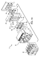
- Figure 1A is a front perspective, exploded view of from the right side of a draw out circuit breaker system 2, including a draw-out circuit breaker 20, a supporting cradle 22, a shutter assembly of independently movable, arc resistant shutters 12A, 12B, and 12C, an arrangement of phase barriers 30, 31, 32, and 33, an arrangement of sheaths 35 for bus bar extensions, an arrangement of bus bar extensions including the bus bar extension 6A, and a back-mold 7.
- the draw out circuit breaker system 2 may be typically installed in a switchgear cabinet (see, for example, Figure 5 ) along with other electrical equipment and devices for distributing, controlling, and/or protecting electrical equipment.
- the supporting cradle 22 is for receiving the draw-out circuit breaker 20 that is movable in and out of contact with an electrical supply.
- the electrical supply may be received via one or more bus bars (not shown) having bus bar extensions, that extend towards the circuit breaker 20 from the back-mold 7 that separates the bus section from the device section of the cabinet, as further explained below.
- phase barriers surround, in part, each bus bar extension to contain arc flash and help quench and transfer an arc before it propagates inside the switchgear cabinet.
- the phase barriers 30, 31, 32, and 33 interleave with cluster shields of the circuit breaker, to contain the energy and channel it into an arc attenuating chamber that lengthens the arc and attenuates the current and temperature until the arc is extinguished.
- independently movable, arc resistant shutters 12A, 12B, and 12C operate within the interleaved phase barriers 30, 31, 32, and 33 and the cluster shields.
- the shutters 12A, 12B, and 12C one for each phase, cover access to the bus bar extensions in the test position or disconnected position of the circuit breaker 20.
- the shutters 12A, 12B, and 12C allow access to the bus bar extensions, independently of each other.
- FIG 1B is a back perspective view from the left side of the draw-out circuit breaker shown in Figure 1A .
- the circuit breaker 20 includes clusters 5A, 5B, and 5C enclosed in part in respective cluster shields 3A, 3B, 3C.
- Each of the clusters is for a specific phase connection of the circuit breaker.
- the clusters are female connectors having opposing stacks of plate-like fingers that will surround and engage the bus bar extensions in the connected position.
- Each cluster and cluster shield comprises a respective connector assembly. In other embodiments, the connector assembly may be solely the connector, such as the cluster of cluster fingers.
- the clusters 5A, 5B, and 5C are the connecting apparatus fitted to the circuit breaker 20 for attaching it to respective phases of electrical power (here shown as three phases A, B, C) received via the bus bar extensions.
- the phases are separated in columns, with line and load connections of the circuit breaker 20 being arranged in rows.
- the system 2 may have four, six, or eight poles.
- clusters 5A', 5B', and 5C' that are the connecting apparatus for a three phase load. It will be appreciated that the load and line connection points can be variously arranged for an individual system according to the designer's dictates.
- Each phase has a dedicated cluster shield 3A, 3B, and 3C that is mounted around its respective line and load clusters.
- the cluster shield 3A, 3B, and 3C is essentially a parallelepiped with four sides or faces forming an open box around the clusters.
- the cluster shields 3A, 3B, and 3C have open faces to permit the clusters to engage with their respective bus bar extensions when the circuit breaker 20 is in a connected position.
- An arc attenuating chamber is formed by sliding a cluster shield 3A, for example, into a slightly larger space between two adjacent phase barriers 30 and 31 ( Fig 1A ), so that the walls of the cluster shield 3A and phase barrier walls 30 and 31 overlap with space therebetween and form the chamber.
- the space between the overlapping walls provides a flue channel 25, indicated generally in Figure 1A , that lengthens the arc and attenuates the current and temperature until the arc is extinguished.
- the flue channel 25 communicates with a chimney 26 to exhaust hot gases produced by the arc.
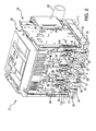
- Figure 2 is a bottom perspective, cut-away view from the right side of a supporting cradle 22 for a draw-out circuit breaker 20.
- the draw-out circuit breaker 20 and the supporting cradle 22 are so constructed that the circuit breaker 20 is supported and can be moved to either the main circuit connected or disconnected position without removing connections or mounting supports.
- the cradle 22 contains functional interconnections for the draw-out circuit breaker 20.
- the circuit breaker 20 includes clusters 5A, 5B, and 5C separated from each other by respective cluster shields 3A, 3B, and 3C.
- Each cluster and cluster shield comprises a respective connector assembly.
- the clusters 5A, 5B, and 5C engage respective bus bar extensions 6A, 6B, and 6C of bus bars for electrical contact.
- the bus bar extensions 6A, 6B, and 6C are sometimes also known as turnable joint mounts (TJM).
- TJM turnable joint mounts
- the bus bar extensions 6A, 6B, and 6C are connected to power supply busses (not shown) located in the bus section of the switchgear cabinet on other side of the back-mold 7 from the circuit breaker 20.
- phase barriers 30, 31, 32, and 33 are mounted to the back-mold 7 at a fixed end and extend therefrom with a free end.
- the free ends of the phase barriers 30, 31, 32, and 33 overlap or interleave with the leading edges of the cluster shields 3A-3C of the circuit breaker connector assembly to form passive arc attenuating chambers.
- Pairs of the phase barriers 30, 31, 32, and 33 surround, in part, each bus bar extension 6A, 6B, and 6C, to contain arc flash and to provide a passive means to attenuate or extinguish an arc before it propagates.
- Figure 2 shows an example embodiment of independently movable, arc resistant shutters 12A, 12B, and 12C that cover access to three phases of power bus bar extensions 6A, 6B, and 6C extending through the back-mold 7.
- the circuit breaker 20 is shown with its line side (or load side) clusters 5A, 5B, and 5C disconnected from the respective power bus bar extensions 6A, 6B, and 6C.
- the arc resistant shutters 12A, 12B, and 12C in conjunction with insulator caps 10, cover access to the bus bar extensions 6A, 6B, and 6C to prevent inadvertent contact with the bus bar extensions when the breaker 20 is withdrawn from the connected position.
- the arc resistant shutters 12A, 12B, and 12C fit within the phase barriers and may be composed of an electrically insulating material such as injection molded or cast plastic, for example polycarbonate, or epoxy, or it may also be a glass or ceramic material.
- the example bus bar extensions 6A, 6B, and 6C are roughly "Y"-shaped, with each example bus bar extension having two tines in a forked or "U” shape, to increase their contact area.
- the example clusters 5A, 5B, and 5C are each arranged as opposed pairs of conductor fingers so as to grasp the respective tines of the intended bus bar extension.
- Other shapes of bus bar extensions 6A, 6B, and 6C and cluster fingers 5A, 5B, and 5C may be used.
- a set of load connectors (not shown in this view) provide connection between the load side of the circuit breaker 20 and a downstream load and are covered in the same fashion.
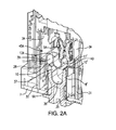
- FIG 2A is a detailed cut-away view of the arc resistant shutter invention of Figure 2 , showing the phase A cluster 5A and the phase A bus bar extension 6A in the disconnected position. To simplify the figure, only one cluster is shown although it is apparent that two may be utilized..
- the figure illustrates an insulator cap 10 that covers the free end of the tine 8 of the bus bar extension 6A and an insulator cap 10' that covers the free end of the tine 8' of the bus bar extension 6A.
- the insulator caps 10 and 10' may be in the form of a coating adhesively applied to the free end of the bus bar extension.
- the insulator caps 10 and 10' are part of a unitary cover or sheath 35 for the bus bar extension 6A, with side walls of the sheath presenting an open area 37 to expose the conductive surface of the bus bar extension 6A.
- the sheath 35 is captured between the bus bar extension 6A and the back-mold 7.
- the insulator caps 10 and 10' and sheath 35 may be composed of an electrically insulating material such as injection molded or cast plastic, for example polycarbonate, or epoxy, it may also be a glass or ceramic material.
- the figure shows openings 11 and 11' in the shutter 12A, through which the respective tines 8 and 8' of the bus bar extension 6A pass when the circuit breaker 20 is in the connected position.
- the shutter 12A slides forward along, i.e. over, the bus bar extension 6A and approaches the insulator caps 10 and 10' bus bar extension.
- the insulator caps 10 and 10' fit closely within the respective openings 11 and 11' in the shutter 12A and provide a finger-safe shield for the opening. That is, the close fit of the shutter 12A with the insulator caps 10 and 10' prevents access to the bus bar extension 6A when the circuit breaker 20 is in the disconnected position.
- the phase barrier 30 is shown with a guide slot 28 indention that receives a boss 41 on the side of the shutter 12A (shown in detail in Figures 4A and 4B ), to guide the shutter 12A as it slides along, i.e. over, the bus bar extension 6A.
- the shutter 12A When the breaker 20 is not present or has been withdrawn to a disconnect position, the shutter 12A will be driven by a spring element 14A (shown in Figure 4B ), to the outermost position of its travel to assume the finger-safe position. In this position, as shown in Figure 2A , all of the energized, conductive surfaces have been covered rendering the space as "touch safe”.
- overlap sections 39 and 40 on the shutter 12A abut the fixed phase barriers 30 and 31.
- the shutters thus help provide containment and interruption of arc energy on the bus bar extensions when the breaker and cluster shields are withdrawn to the disconnect position.
- the arc resistant performance is maintained even when the breaker is extracted from the disconnect position or removed from the cradle.
- An arc attenuating chamber 45A is formed by the cluster shield 3A, overlapped with the two adjacent phase barriers 30 and 31 so that the leading edges of the cluster shield 3A and the free ends of the phase barriers 30 and 31 form the chamber.
- the phase barrier 30 is shown in Figure 2A with the guide slot 28 indention that receives the boss 41 on the side of the shutter 12A (shown in detail in Figures 4A and 4B ), to guide the shutter 12A as it slides in the arc attenuating chamber 45A.
- the arc attenuating chamber 45A includes the interleaved phase barriers 30, 31 and cluster shield 3A, the arc resistant shutter 12A, the sheath 35 with the insulator caps 10, 10' on the tips of the bus bar extension 6A, the overlap sections 39 and 40 on the shutter 12A, which abut the fixed phase barriers 30 and 31, and the cradle back-mold 7.
- FIG 4A is a front perspective, cut-away view from the right side of an example embodiment of the independently movable, arc resistant shutter 12.
- the figure shows details of the cut-away openings 11 and 11' in the shutter 12, through which the respective tines 8 and 8' of the bus bar extension 6A can pass, to connect with the cluster fingers 5A of the circuit breaker 20.
- a second set of openings 11A and 11A' will allow the tines of a respective load bus bar extension to pass through the shutter 12.
- the overlap sections 39 and 40 are shown, which abut the fixed phase barriers 30 and 31.
- a boss 41 on the side of the shutter 12 rides in the guide slot 28 ( Figure 2A ) of the phase barrier 30, as the shutter 12 moves forward and backward.
- Figure 4B is a back perspective view from the right side of the arc resistant shutter 12.
- the figure shows details of a reinforced structure 24 of ribs to strengthen the shutter, to enhance arc resistance.
- the figure shows details of a spring biased support 14A that may be mounted to or may press against or be braced against the back-mold 7, for example.
- the spring bias moves the shutter 12A forward along the bus bar extension 6A when the circuit breaker 20 is moved into the disconnected position.
- the spring 14A is a spring biased support for the moveable shutter 12A, mounted in a fixed position, on or against the back-mold 7, with respect to the bus bar extension 6A.
- the arc resistant shutter 12A is designed to resist the pressure created during an arcing event, to insure that released gases are sufficiently cooled so as to pose no risk to the user, and that any arc formed between energized conductors will quickly self-extinguish.
- the mechanical strength of the arc resistant shutter 12A is enhanced by the material properties and the generous sections of the reinforcing ribs 24.
- the cooling and extinguishing properties are enhanced by the use of overlap sections 39 and 40 between the shutters and the phase barriers 30, 31, 32, and 33 and by the close fit of the insulator caps 10 and 10' within the openings 11 and 11' in the shutters.
- FIG. 5 is a front perspective view from the right side, of a switchgear cabinet, being a motor control center (MCC) cabinet 60 into which has been inserted a motor control unit 50 for connection to vertical bus bars via phase barriers 56 shown at the back of the cabinet 60.
- MCC motor control center
- the motor control unit has a handle-cam mechanism (not shown) to rack-in the unit into the MCC cabinet, which mechanically locks the motor control unit into place in the MCC cabinet.
- the operator must then actuate a separate connect/disconnect handle on the front of the motor control unit, to advance the movable female connectors, which can be clip-like conductive structures akin to clusters, of the motor control unit to electrically connect them to the bus bars.
- Figure 5A is a front perspective view from the left side, of the motor control unit 50 in a connected position to the vertical bus bars 54A, 54B, and 54C, via the phase barriers 56 mounted in a rear bus frame 51 in the motor control center cabinet 60 (not shown).
- An exterior face of a back wall of the motor control unit is configured to be located adjacent to the vertical bus bars when the motor control unit has been inserted into the motor control center cabinet.
- connector assemblies of a circuit breaker in the motor control unit 50 are connected to the vertical bus bars 54A, 54B, and 54C.
- a connector assembly is comprised of the female connector, for example 52A (collectively 52A, 52B, 52C), and one or both of a connector protector, e.g. 53A, surrounding the female connector 52A, and a fixed shroud 57A surrounding the connector protector 53A.
- the connector assembly may be solely the connector, such as the female connector.
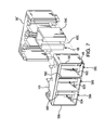
- FIG. 6 is a front perspective view from the top, right side of the phase barriers 56 mounted in the rear bus frame 51 in the motor control center cabinet (not shown).
- female connectors 52A, 52B, 52C are placed in progressive states of connection to the bus bars for explanatory purposes, but will be understood to move as a unit and be in the same state of connection during actual operation.
- the phase barriers 56A and 56B partially surround the vertical bus bar phase 54A.
- the phase barriers 56B and 56C partially surround the vertical bus bar phase 54B.
- the phase barriers 56C and 56D partially surround the vertical bus bar phase 54C.
- An insulator cap 62A, 62B, and 62C is shown covering the free, front end of each respective bus bar phase 54A, 54B, and 54C.
- An independently movable, arc resistant shutter e.g. 64A
- 64A is located around each bus bar 54A-54C, and within the phase barriers, collectively 56, also surrounding each of the bus bars.
- the shutter assemblies comprising the independently movable, arc resistant shutters 64A, 64B, and 64C and respective insulator caps 62A, 62B, and 62C, prevent access to the respective bus bars 54A, 54B, and 54C when the motor control unit 50 is in the disconnected position and allow access to the respective bus bars 54A, 54B, and 54C when the motor control unit 50 is in the connected position of Figure 5A .
- an arc attenuating chamber 58A is formed for the A phase bus connection area by sliding the fixed shroud 57A surrounding female connector 52A (e.g. shown in Figure 9A ), into the slightly larger space between phase barriers 56A and 56B, so that the leading edges of the fixed shroud 57A and the free ends of the phase barriers 56A and 56B overlap and form the chamber 58A.
- An arc attenuating chamber 58B and 58C is likewise formed for each of the B and C phase busses 54B and 54C.
- the attenuating chambers 58A, 58B, and 58C will contain the energy of an arc flash produced between each female connector 52 and bus bar 54 and channel the energy into respective flues 55A, 55B, and 55C.
- the phase barrier assembly 56 includes a shutter assembly 68 that comprises an insulator cap 62C and an independently movable, arc resistant shutter 64C, for covering access to the bus bar 54C when the motor control unit 50 is in a disconnected position.
- the shutter 64C operates within the arc attenuating chamber 58C and allows the female connectors 52 to access the bus bars 54 when the motor control unit 50 is in the connected position.
- the female connectors 52A, 52B, 52C of the motor control unit are as yet electrically disconnected from the bus bars 54A, 54B, 54C, as shown in Figure 9A .
- the operator may actuate the connect/disconnect handle on the front of the motor control unit 50, to advance the female connectors to electrically connect them to the bus bars, as shown in Figure 9A' .
- the shutters 64A, 64B, 64C slide along the bus bars backwardly away from the insulator caps 62A, 62B, 62C, in response to the force applied by the leading edge of the female connectors, and the female connectors electrically connect to the respective bus bars.
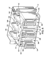
- FIG. 7 is a front perspective, exploded view from the top, right side of a front section 101 of the phase barrier assembly 56, the independently movable, arc resistant shutter 64C, and a rear section of the phase barriers 56'.
- the rear section of the phase barriers 56' fits on the back of the three bus bar phases 54A, 54B, and 54C (not shown) and the front section 101 of the phase barrier 56 fits on the front of the three bus bar phases.
- the front section 101 of the phase barrier 56 and rear section phase barrier 56' snap together to partially surround the bus bar phases 54A, 54B, and 54C, to provide a passive means to attenuate or extinguish arcs.
- the independently movable, arc resistant shutter 64C is shown aligned to slide between the phase barriers 56C and 56D.
- the insulator caps, collectively 62, are positioned within the front section of the phase barrier assembly 56 and fit on the front, free end, of their respective bus bars 54, when assembled.
- a spring 66 (shown in Figure 9A ) is formed on the back of the arc resistant shutter 64C to provide a spring biased force that pushes against a fixed structure, such as the rear section of the phase barriers 56'.
- the shutter 64C is slideable along the bus bar 54C toward the insulator cap 62C, in response to the force applied by the spring 66, when the motor control unit is in the disconnected position.
- the spring 66 is a spring biased support for the shutter 64C, preferably mounted in a fixed position on or against the rear section of the phase barriers 56' with respect to the bus 54C.
- FIG. 8A is a top, back perspective view from the right, of the motor control unit 50 of Figure 9A , showing the connector protectors 53A, 53B, and 53C surrounding the respective female connectors 52A, 52B and 52C, with a leading edge of the connector protector projecting out in a position to apply a force on the respective shutter 64A, 64B, and 64C to slide the shutter along the respective bus bar 54A, 54B, 54C backwardly away from the respective insulator cap 62A, 62B, and 62C, when in the connected position.
- Figure 8B is a top, back perspective view from the right, of the motor control unit 50 of Figure 9B , showing the fixed shrouds 57A, 57B, and 57C surrounding the respective connector protector 53A, 53B, and 53C, with a bottom portion 57A', 57B', and 57C', for example, below the respective female connector 52A, 52B, and 52C, having a leading edge of the bottom portion 57A', 57B', and 57C' projecting out in a position to apply a force on the respective shutter 64A, 64B, and 64C to slide the shutter along the bus bar 54A, 54B, and 54C away from the insulator cap 62A, 62B, and 62C, when in the connected position.
- Figure 8C is a top, back perspective view from the right, of the motor control unit 50 of Figure 9C , showing the female connectors 52A, 52B, and 52C with their leading edges projecting out in a position to apply a force on the respective shutter to slide the shutter along the bus bar away from the insulator cap, when in the connected position.
- Figure 9A is a top view of the motor control unit 50 of Figure 8A , showing the respective female connectors 52A, 52B, 52C disconnected from the respective bus bars 54A, 54B, 54C and the respective insulator caps 62A, 62B, 62C fitting closely in front of the bus bars within the openings in the shutters 64A, 64B, 64C, thereby providing an arc resistant shield for the openings to prevent access to the bus bars when in the disconnected position.
- Pairs of phase barriers 56A, 56B, 56C, 56D surround in part each bus bar 54A, 54B, and 54C.
- the arc attenuating chamber 58A contains arc flash and helps quench and transfer an arc before it propagates.
- the arc attenuating chamber 58A is formed by sliding fixed shroud 57A, for example, into the slightly larger space between phase barriers 56A and 56B, so that the leading edges of the fixed shroud 57A and phase barriers 56A and 56B overlap and form the chamber 58A.
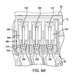
- Figure 9A' is a top view of the motor control unit of Figure 9A , showing the female connectors 52A, 52B, 52C connected to the respective bus bars 54A, 54B, 54C.
- the leading edge of the respective connector protectors 53A, 53B, and 53C surrounding the female connector applies a force on the shutter to slide the shutter along the bus bar backwardly away from the insulator cap, when in the connected position.
- the female connectors are shown fully connected with the bus bars.
- the free ends of the respective phase barriers 56A and 56B for example, overlap the leading edge of a respective fixed shroud 57A surrounding the connector protector 53A, when in the connected position, to provide a passive means to channel arcs preferably to attenuate or extinguish the arcs.
- Figure 9B is a top view of the motor control unit 50 of Figure 8B , showing an example embodiment, wherein the leading edge of the respective fixed shroud 57A, 57B, 57C surrounding the respective connector protector, applies a force on the respective shutter to slide the shutter along the respective bus bar away from the respective insulator cap, when in the connected position.
- a bottom portion 57A' for example, below the female connector 52A, projects out in a position to apply the force on the shutter.
- Figure 9C is a top view of the motor control unit 50 of Figure 8C , showing an example embodiment, wherein the leading edge of the respective female connectors 52A, 52B, 52C applies a force on the respective shutter to slide the shutter along the respective bus bar away from the respective insulator cap, when in the connected position.
Landscapes
- Engineering & Computer Science (AREA)
- Power Engineering (AREA)
- Patch Boards (AREA)
Abstract


Description
- The invention disclosed relates to arc resistant electrical distribution equipment.
- Circuit breakers used in switchgear cabinets are often constructed in a draw-out configuration that allows breaker insertion or removal by moving the breaker in a cradle assembly. The draw-out breakers have a connected position in which clusters, i.e. connectors having opposing stacks of plate-like fingers, engage bus bar extensions of bus bars in the switchgear cabinet. In a disconnected position, including the test position in some types of breakers, the clusters are disconnected from the bus bar extensions. To cover access to, and prevent inadvertent contact with, the bus bar extensions when the breaker is in the disconnected position, shutter systems have been utilized across a back plane of the cradle assembly. One shutter system includes sliding panels that protect all breaker phases at the same time. Another shutter system, taught in the copending International Application No.
PCT/US2013/031345, filed March 14, 2013 , entitled "Independent Shutter System for Rack-In Breakers", of common ownership herewith, includes a curtain having a pair of movable "hands" that are mounted to slide on a curtain mount, which, in turn, is mounted to slide on a pedestal that is mounted to a back-mold. - Circuit breakers are also used in motor control units, wherein the motor control unit may be inserted or removed from a motor control center (MCC) switchgear cabinet without shutting down all power to the cabinet. The motor control units have a connected position in which female connectors of the breakers are connected to respective bus bars, and a disconnected position in which the female connectors are disconnected from the bus bars. To cover access to, and prevent inadvertent contact with, the bus bars when the motor control unit is in the disconnected position, a common shutter system has been utilized across all power phases supplying the motor control unit.
- Both draw-out circuit breakers and motor control units may share the requirement of making and breaking connections with installed bus bars or bus bar extensions i.e. the incoming power conductors contained in the switchgear cabinet. The making and breaking of connections and the handling of heavy currents in the area of connection between control devices like circuit interrupters (breakers), makes this area of the cabinet particularly susceptible to arcing. An arc flash is the rapid release of energy due to an arcing fault between phases, neutral or ground contacts. The resulting arc flash has the potential to cause considerable damage, including arcing-induced erosion of the contacts and injury to operators. The temperature of an arc flash may be capable of vaporizing metal and sending a blast of plasma and molten metal in all directions with extreme force. Damage may be caused to the switchgear both by the explosion of the arc flash and by the heat radiating from the blast. It is important to minimize the potential for harm to equipment and people by containing and redirecting the arc energy out from the switchgear.
- Arc resistance pertains to the ability to withstand the destructive energy released during an arc flash, by interrupting and channeling the energy away from personnel and adjacent equipment. Passive arc resistance may include directed venting of the arc flash energy and gases out of the switchgear and reinforcement of the switchgear structure to withstand the blast. An example of passive arc resistance from the applicant features so-called arc-block technology which provides capability to passively attenuate and extinguish arc events, and which is described in the copending International Patent Application
WO 2013/158723, published October 24, 2013 , entitled "Passive Arc Management System With Flue Chamber", of common ownership herewith, wherein an electrical distribution cabinet has an arc attenuating chamber surrounding the electrical connection point between a cluster, i.e. electrical power connector, of a draw out circuit breaker and a bus bar extension. The arc attenuating chamber is formed by sliding a cluster shield surrounding a cluster at the back of the breaker, into a slightly larger phase barrier that surrounds the bus bar extension, so that the leading edges of the cluster shield and phase barrier overlap and form the chamber. The arc attenuating chamber provides a flue channel that lengthens the arc and attenuates the current and temperature until the arc is extinguished. The mechanism is particularly suited for draw-out circuit breaker connections in a switch gear cabinet. - In an example embodiment of the present invention, an independently-moveable arc-resistant shutter assembly fits inside an arc attenuating chamber of an individual phase surround at the point of electrical connection between a circuit interrupting device, and a bus bar or bus bar extension. The point of connection will typically be referred to as the cluster of a draw out circuit breaker or the female connector of a motor control unit. The terms circuit interrupting device and circuit breaker may be used interchangeably herein and will be understood by the person having ordinary skill in the art to have the broader meaning.
- The shutter assembly provides a physical barrier to debris, tools, and operator fingers, denying access to the bus bar or bus bar extension when the device, i.e. breaker, is disconnected from the bus bar or bus bar extension. The main body of the shutter has an opening through which the bus bar or bus bar extension passes.
- The shutter assembly includes an insulator cap on a free end of the bus bar or bus bar extension. The shutter assembly includes an independently moveable shutter composed of an insulator material, which slides within the arc attenuating chamber. The shutter is slideable along the bus bar or bus bar extension away from the insulator cap, in response to a force applied by a leading edge of a connector assembly for the circuit interrupting device, when the device is being connected to the bus bar or bus bar extension.
- In some embodiments, such as in a draw out circuit breaker, the connector assembly may include a cluster and its cluster shield. In other embodiments, such as in a motor control unit, the connector assembly may include a female connector and its connector protector and/or its fixed shroud. In still other embodiments, such as in either a draw out circuit breaker or a motor control unit, the connector assembly may be solely the connector, such as a cluster or a female connector. The independently moveable shutter is arranged to be contacted and moved by the connector assembly, when the circuit interrupter device is connected to the power supply from the bus bar or bus bar extension.
- When the device is disconnected from the bus bar or bus bar extension the moveable shutter slides along the bus bar or bus bar extension toward the insulator cap, in response to a force applied by a spring biased support. In the disconnected position, the insulator cap fits closely within the opening in the shutter, thereby providing the physical barrier to debris, tools, and operator fingers, denying access to the bus bar or bus bar extension.
- The shutter is a reinforced structure composed of an insulator material, which is a simple and strong design able to resist the destructive energy released during an arc flash. The insulator cap may be a coating of insulator material or it may be part of an insulator cover or sheath fit over the bus bar or bus bar extension and covering the free end thereof. The shutter assembly comprising the shutter and insulator cap, fits within the arc attenuating chamber of an individual phase, and is thus reliable while being easy to make and use.
-
-
Figure 1A is a front right side perspective, exploded view of switchgear cabinet a draw-out circuit breaker, a supporting cradle, an arrangement of independently movable arc resistant shutters, an arrangement of phase barriers, and a back-mold. -
Figure 1B is a back perspective view from the right side of the draw-out circuit breaker shown inFigure 1A . -
Figure 2 is a bottom perspective, cut-away view from the right side of a supporting cradle for a draw-out circuit breaker, showing an example embodiment of independently movable, arc resistant shutters that cover access to bus bar extensions in the supporting cradle. The circuit breaker is shown with its cluster fingers disconnected from the bus bar extensions and the arc resistant shutters covering access to the bus bar extensions to prevent inadvertent contact with the bus bar extensions. -
Figure 2A is a detailed cut-away view of the arc resistant shutter invention ofFigure 2 , showing one phase of the cluster fingers and the bus bar extensions in the disconnected position, illustrating an insulator cap that covers the free end of the bus bar extension. The figure shows an opening in the shutter, through which the bus bar extension passes in the connected position. To simplify the figure, only one cluster is shown. -
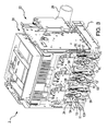
Figure 3 is a bottom perspective, cut-away view from the right side of the supporting cradle for the draw-out circuit breaker ofFigure 1A , showing the cluster fingers of the circuit breaker connected to the bus bar extensions and the arc resistant shutters sliding backward along the bus bar extensions to allow access for electrical contact. -
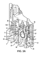
Figure 3A is a detailed cut-away view of the arc resistant shutter invention ofFigure 3 , showing one phase of the cluster fingers and the bus bar extensions in the connected position, illustrating the arc resistant shutters sliding backward along the bus bar extensions to allow access for electrical contact. To simplify the figure, only one cluster is shown. -
Figure 4A is a front perspective, cut-away view from the right side of an example embodiment of the independently movable, arc resistant shutter. The figure shows details of the opening in the shutter, through which the bus bar extension passes. -
Figure 4B is a back perspective, cut-away view from the right side of the arc resistant shutter ofFigure 4A . The figure shows details of the opening in the shutter, through which the bus bar extension passes, details of a reinforced structure of the shutter, to enhance arc resistance, and details of a spring biased support that moves the shutter forward along the bus bar extension when the circuit breaker is moved into the disconnected position. -
Figure 5 a front perspective view from the right side, of a motor control center (MCC) cabinet into which has been inserted a motor control unit for connection to vertical bus bars via phase barriers shown lining the back of the cabinet. -
Figure 5A is a front perspective view from the left side, of the motor control unit in a connected position to the vertical bus bars, via the phase barriers mounted in a rear bus frame in the motor control center cabinet (not shown). -
Figure 6 is a front perspective view from the top, right side of the phase barriers mounted in the rear bus frame in the motor control center cabinet (not shown). -
Figure 7 is a front perspective, exploded view from the top, right side of a front section of the phase barriers, the arc resistant shutter, and a rear section of the phase barriers. -
Figure 8A is a top, back perspective view from the right, of the motor control unit, showing the connector protector surrounding the female connector, projecting out in a position to apply a force on the shutter to slide the shutter along the bus bar away from the insulator cap, when in the connected position. -
Figure 8B is a top, back perspective view from the right, of the motor control unit, showing the fixed shroud surrounding the connector protector, the fixed shroud projecting out in a position to apply a force on the shutter to slide the shutter along the bus bar away from the insulator cap, when in the connected position. -
Figure 8C is a top, back perspective view from the right, of the motor control unit, showing the female connector projecting out in a position to apply a force on the shutter to slide the shutter along the bus bar away from the insulator cap, when in the connected position. -
Figure 9A is a top view of the motor control unit with the female connectors disconnected from bus bar. In the disconnected position, the insulator cap fits closely within the opening in the shutter, to deny access to the bus bar. -
Figure 9A' is a top view of the motor control unit ofFigure 9A , showing the leading edge of the connector protector surrounding the female connector, applying a force on the shutter to slide the shutter along the bus bar away from the insulator cap, when in the connected position. -
Figure 9B is a top view of the motor control unit, showing the leading edge of the fixed shroud surrounding the connector protector and the female connector, applying a force on the shutter to slide the shutter along the bus bar away from the insulator cap, when in the connected position. In an example embodiment, the fixed shroud has an extension beneath the female connector, to apply the force on the shutter. -
Figure 9C is a top view of the motor control unit, showing the leading edge of the female connector applying a force on the shutter to slide the shutter along the bus bar away from the insulator cap, when in the connected position. -
Figure 1A is a front perspective, exploded view of from the right side of a draw outcircuit breaker system 2, including a draw-outcircuit breaker 20, a supportingcradle 22, a shutter assembly of independently movable, arcresistant shutters phase barriers sheaths 35 for bus bar extensions, an arrangement of bus bar extensions including thebus bar extension 6A, and a back-mold 7. The draw outcircuit breaker system 2 may be typically installed in a switchgear cabinet (see, for example,Figure 5 ) along with other electrical equipment and devices for distributing, controlling, and/or protecting electrical equipment. The supportingcradle 22 is for receiving the draw-outcircuit breaker 20 that is movable in and out of contact with an electrical supply. Within the switchgear cabinet, the electrical supply may be received via one or more bus bars (not shown) having bus bar extensions, that extend towards thecircuit breaker 20 from the back-mold 7 that separates the bus section from the device section of the cabinet, as further explained below. - The phase barriers surround, in part, each bus bar extension to contain arc flash and help quench and transfer an arc before it propagates inside the switchgear cabinet. The
phase barriers - To protect against inadvertent contact with the bus bar extensions when the
circuit breaker 20 is in a test position or in a disconnected position (i.e., when thecircuit breaker 20 is disconnected from the electrical supply), independently movable, arcresistant shutters phase barriers shutters circuit breaker 20. When thecircuit breaker 20 is in a connected position, and as discussed in more detail below, theshutters -
Figure 1B is a back perspective view from the left side of the draw-out circuit breaker shown inFigure 1A . Thecircuit breaker 20 includesclusters clusters circuit breaker 20 for attaching it to respective phases of electrical power (here shown as three phases A, B, C) received via the bus bar extensions. The phases are separated in columns, with line and load connections of thecircuit breaker 20 being arranged in rows. In other examples, thesystem 2 may have four, six, or eight poles. Also shown areclusters 5A', 5B', and 5C' that are the connecting apparatus for a three phase load. It will be appreciated that the load and line connection points can be variously arranged for an individual system according to the designer's dictates. - Each phase has a
dedicated cluster shield cluster shield circuit breaker 20 is in a connected position. - An arc attenuating chamber is formed by sliding a
cluster shield 3A, for example, into a slightly larger space between twoadjacent phase barriers 30 and 31 (Fig 1A ), so that the walls of thecluster shield 3A andphase barrier walls flue channel 25, indicated generally inFigure 1A , that lengthens the arc and attenuates the current and temperature until the arc is extinguished. Theflue channel 25 communicates with achimney 26 to exhaust hot gases produced by the arc. -
Figure 2 is a bottom perspective, cut-away view from the right side of a supportingcradle 22 for a draw-outcircuit breaker 20. The draw-outcircuit breaker 20 and the supportingcradle 22 are so constructed that thecircuit breaker 20 is supported and can be moved to either the main circuit connected or disconnected position without removing connections or mounting supports. Thecradle 22 contains functional interconnections for the draw-outcircuit breaker 20. - In an example embodiment, the
circuit breaker 20 includesclusters clusters bus bar extensions bus bar extensions bus bar extensions mold 7 from thecircuit breaker 20. - The
phase barriers mold 7 at a fixed end and extend therefrom with a free end. The free ends of thephase barriers phase barriers bus bar extension -
Figure 2 shows an example embodiment of independently movable, arcresistant shutters bus bar extensions mold 7. Thecircuit breaker 20 is shown with its line side (or load side)clusters bus bar extensions resistant shutters bus bar extensions breaker 20 is withdrawn from the connected position. The arcresistant shutters - The example
bus bar extensions example clusters bus bar extensions cluster fingers circuit breaker 20 and a downstream load and are covered in the same fashion. -
Figure 2A is a detailed cut-away view of the arc resistant shutter invention ofFigure 2 , showing thephase A cluster 5A and the phase Abus bar extension 6A in the disconnected position. To simplify the figure, only one cluster is shown although it is apparent that two may be utilized.. The figure illustrates aninsulator cap 10 that covers the free end of thetine 8 of thebus bar extension 6A and an insulator cap 10' that covers the free end of the tine 8' of thebus bar extension 6A. The insulator caps 10 and 10' may be in the form of a coating adhesively applied to the free end of the bus bar extension. As illustrated, the insulator caps 10 and 10' are part of a unitary cover orsheath 35 for thebus bar extension 6A, with side walls of the sheath presenting anopen area 37 to expose the conductive surface of thebus bar extension 6A. Thesheath 35 is captured between thebus bar extension 6A and the back-mold 7. The insulator caps 10 and 10' andsheath 35 may be composed of an electrically insulating material such as injection molded or cast plastic, for example polycarbonate, or epoxy, it may also be a glass or ceramic material. - The figure shows
openings 11 and 11' in theshutter 12A, through which therespective tines 8 and 8' of thebus bar extension 6A pass when thecircuit breaker 20 is in the connected position. When the circuit breaker is moved into the disconnected position shown inFigure 2A , theshutter 12A slides forward along, i.e. over, thebus bar extension 6A and approaches the insulator caps 10 and 10' bus bar extension. In this position, the insulator caps 10 and 10' fit closely within therespective openings 11 and 11' in theshutter 12A and provide a finger-safe shield for the opening. That is, the close fit of theshutter 12A with the insulator caps 10 and 10' prevents access to thebus bar extension 6A when thecircuit breaker 20 is in the disconnected position. Thephase barrier 30 is shown with aguide slot 28 indention that receives aboss 41 on the side of theshutter 12A (shown in detail inFigures 4A and 4B ), to guide theshutter 12A as it slides along, i.e. over, thebus bar extension 6A. - When the
breaker 20 is not present or has been withdrawn to a disconnect position, theshutter 12A will be driven by aspring element 14A (shown inFigure 4B ), to the outermost position of its travel to assume the finger-safe position. In this position, as shown inFigure 2A , all of the energized, conductive surfaces have been covered rendering the space as "touch safe". - Referring to
Figs. 3 and3A , from a disconnected position, thebreaker 20 has been racked into thecradle 22 by the user to the connected position. The movement of the breaker toward the back-mold 7 causes each cluster shield, e.g. 3A, to push on the respective shutter, e.g. 12A, and move it backwards. In the process of pushing on theshutters 12A-12C, the open areas 37 (Figure 3A ) of the bus bar extension shields 35 will become exposed and allow the respective breaker cluster fingers, e.g. 5A, to make electrical contact to the respective bus bar extensions, e.g. 6A, as the breaker reaches the connected position. Again referring toFigure 2A ,overlap sections shutter 12A, abut thefixed phase barriers - An
arc attenuating chamber 45A is formed by thecluster shield 3A, overlapped with the twoadjacent phase barriers cluster shield 3A and the free ends of thephase barriers phase barrier 30 is shown inFigure 2A with theguide slot 28 indention that receives theboss 41 on the side of theshutter 12A (shown in detail inFigures 4A and 4B ), to guide theshutter 12A as it slides in thearc attenuating chamber 45A. Thearc attenuating chamber 45A includes the interleavedphase barriers cluster shield 3A, the arcresistant shutter 12A, thesheath 35 with the insulator caps 10, 10' on the tips of thebus bar extension 6A, theoverlap sections shutter 12A, which abut thefixed phase barriers mold 7. -
Figure 4A is a front perspective, cut-away view from the right side of an example embodiment of the independently movable, arcresistant shutter 12. In conjunction withFigure 3A , the figure shows details of the cut-awayopenings 11 and 11' in theshutter 12, through which therespective tines 8 and 8' of thebus bar extension 6A can pass, to connect with thecluster fingers 5A of thecircuit breaker 20. A second set ofopenings shutter 12. Theoverlap sections fixed phase barriers boss 41 on the side of theshutter 12 rides in the guide slot 28 (Figure 2A ) of thephase barrier 30, as theshutter 12 moves forward and backward. -
Figure 4B is a back perspective view from the right side of the arcresistant shutter 12. The figure shows details of a reinforcedstructure 24 of ribs to strengthen the shutter, to enhance arc resistance. The figure shows details of a springbiased support 14A that may be mounted to or may press against or be braced against the back-mold 7, for example. The spring bias moves theshutter 12A forward along thebus bar extension 6A when thecircuit breaker 20 is moved into the disconnected position. In this manner thespring 14A is a spring biased support for themoveable shutter 12A, mounted in a fixed position, on or against the back-mold 7, with respect to thebus bar extension 6A. - The arc
resistant shutter 12A is designed to resist the pressure created during an arcing event, to insure that released gases are sufficiently cooled so as to pose no risk to the user, and that any arc formed between energized conductors will quickly self-extinguish. The mechanical strength of the arcresistant shutter 12A is enhanced by the material properties and the generous sections of the reinforcingribs 24. The cooling and extinguishing properties are enhanced by the use ofoverlap sections phase barriers openings 11 and 11' in the shutters. -
Figure 5 is a front perspective view from the right side, of a switchgear cabinet, being a motor control center (MCC)cabinet 60 into which has been inserted amotor control unit 50 for connection to vertical bus bars viaphase barriers 56 shown at the back of thecabinet 60. One difference between a motor control unit and a draw-out circuit breaker, is that the motor control unit is not normally connected to the bus bars when the unit is initially racked into the MCC cabinet. The motor control unit has a handle-cam mechanism (not shown) to rack-in the unit into the MCC cabinet, which mechanically locks the motor control unit into place in the MCC cabinet. The operator must then actuate a separate connect/disconnect handle on the front of the motor control unit, to advance the movable female connectors, which can be clip-like conductive structures akin to clusters, of the motor control unit to electrically connect them to the bus bars. -
Figure 5A is a front perspective view from the left side, of themotor control unit 50 in a connected position to the vertical bus bars 54A, 54B, and 54C, via thephase barriers 56 mounted in arear bus frame 51 in the motor control center cabinet 60 (not shown). An exterior face of a back wall of the motor control unit is configured to be located adjacent to the vertical bus bars when the motor control unit has been inserted into the motor control center cabinet. Referring also toFigure 9A' , connector assemblies of a circuit breaker in themotor control unit 50, are connected to the vertical bus bars 54A, 54B, and 54C. A connector assembly is comprised of the female connector, for example 52A (collectively 52A, 52B, 52C), and one or both of a connector protector, e.g. 53A, surrounding thefemale connector 52A, and a fixedshroud 57A surrounding theconnector protector 53A. In other embodiments, the connector assembly may be solely the connector, such as the female connector. -
Figure 6 is a front perspective view from the top, right side of thephase barriers 56 mounted in therear bus frame 51 in the motor control center cabinet (not shown). In the figure,female connectors phase barriers bus bar phase 54A. Thephase barriers bus bar phase 54B. Thephase barriers bus bar phase 54C. Aninsulator cap bus bar phase bus bar 54A-54C, and within the phase barriers, collectively 56, also surrounding each of the bus bars. The shutter assemblies comprising the independently movable, arcresistant shutters respective bus bars motor control unit 50 is in the disconnected position and allow access to therespective bus bars motor control unit 50 is in the connected position ofFigure 5A . - When the
motor control unit 50 is connected, anarc attenuating chamber 58A is formed for the A phase bus connection area by sliding the fixedshroud 57A surroundingfemale connector 52A (e.g. shown inFigure 9A ), into the slightly larger space betweenphase barriers shroud 57A and the free ends of thephase barriers chamber 58A. Anarc attenuating chamber chambers respective flues - Referring to
Figure 7 , thephase barrier assembly 56 includes ashutter assembly 68 that comprises aninsulator cap 62C and an independently movable, arcresistant shutter 64C, for covering access to thebus bar 54C when themotor control unit 50 is in a disconnected position. Theshutter 64C operates within thearc attenuating chamber 58C and allows the female connectors 52 to access the bus bars 54 when themotor control unit 50 is in the connected position. - After the
motor control unit 50 has been racked into place in theMCC cabinet 60, thefemale connectors Figure 9A . Thereafter, the operator may actuate the connect/disconnect handle on the front of themotor control unit 50, to advance the female connectors to electrically connect them to the bus bars, as shown inFigure 9A' . In one embodiment (Figure 9C ), theshutters -
Figure 7 is a front perspective, exploded view from the top, right side of afront section 101 of thephase barrier assembly 56, the independently movable, arcresistant shutter 64C, and a rear section of the phase barriers 56'. The rear section of the phase barriers 56' fits on the back of the three bus bar phases 54A, 54B, and 54C (not shown) and thefront section 101 of thephase barrier 56 fits on the front of the three bus bar phases. Thefront section 101 of thephase barrier 56 and rear section phase barrier 56' snap together to partially surround the bus bar phases 54A, 54B, and 54C, to provide a passive means to attenuate or extinguish arcs. In the exploded view, the independently movable, arcresistant shutter 64C is shown aligned to slide between thephase barriers - The insulator caps, collectively 62, are positioned within the front section of the
phase barrier assembly 56 and fit on the front, free end, of their respective bus bars 54, when assembled. - A spring 66 (shown in
Figure 9A ) is formed on the back of the arcresistant shutter 64C to provide a spring biased force that pushes against a fixed structure, such as the rear section of the phase barriers 56'. Theshutter 64C is slideable along thebus bar 54C toward theinsulator cap 62C, in response to the force applied by thespring 66, when the motor control unit is in the disconnected position. In this manner thespring 66 is a spring biased support for theshutter 64C, preferably mounted in a fixed position on or against the rear section of the phase barriers 56' with respect to thebus 54C. - The connector assembly of the breaker of the
motor control unit 50 may be designed in a number of ways to make contact with the leading edge of the shutter. Three designs are shown.Figure 8A is a top, back perspective view from the right, of themotor control unit 50 ofFigure 9A , showing theconnector protectors female connectors respective shutter respective bus bar respective insulator cap -
Figure 8B is a top, back perspective view from the right, of themotor control unit 50 ofFigure 9B , showing the fixed shrouds 57A, 57B, and 57C surrounding therespective connector protector bottom portion 57A', 57B', and 57C', for example, below the respectivefemale connector bottom portion 57A', 57B', and 57C' projecting out in a position to apply a force on therespective shutter bus bar insulator cap -
Figure 8C is a top, back perspective view from the right, of themotor control unit 50 ofFigure 9C , showing thefemale connectors -
Figure 9A is a top view of themotor control unit 50 ofFigure 8A , showing the respectivefemale connectors respective bus bars shutters - Pairs of
phase barriers bus bar arc attenuating chamber 58A contains arc flash and helps quench and transfer an arc before it propagates. Thearc attenuating chamber 58A is formed by sliding fixedshroud 57A, for example, into the slightly larger space betweenphase barriers shroud 57A andphase barriers chamber 58A. -
Figure 9A' is a top view of the motor control unit ofFigure 9A , showing thefemale connectors respective bus bars respective connector protectors respective phase barriers shroud 57A surrounding theconnector protector 53A, when in the connected position, to provide a passive means to channel arcs preferably to attenuate or extinguish the arcs. -
Figure 9B is a top view of themotor control unit 50 ofFigure 8B , showing an example embodiment, wherein the leading edge of the respective fixedshroud bottom portion 57A', for example, below thefemale connector 52A, projects out in a position to apply the force on the shutter. -
Figure 9C is a top view of themotor control unit 50 ofFigure 8C , showing an example embodiment, wherein the leading edge of the respectivefemale connectors - Although specific example embodiments of the invention have been disclosed, persons of skill in the art will appreciate that changes may be made to the details described for the specific example embodiments, without departing from the spirit and the scope of the invention.
Claims (18)
- A shutter assembly for a switchgear cabinet, comprising:a shutter moveable along a bus bar or bus bar extension of a power bus, the shutter for covering access to the bus bar or bus bar extension, in a disconnected position for a circuit breaker,the bus bar or bus bar extension having an insulator cap covering a free end thereof,the shutter allowing access to the bus bar or bus bar extension in a connected position for the circuit breaker, the connected position being when a connector assembly of the circuit breaker is connected to the bus bar or bus bar extension,the movable shutter includinga spring biased support,the moveable shutter having an opening through which the bus bar or bus bar extension passes, the shutter being slideable along the bus bar or bus bar extension away from the insulator cap, in response to a force applied by a leading edge of the connector assembly when in the connected position, andthe shutter being slideable along the bus bar or bus bar extension toward the insulator cap, in response to a force applied by the spring biased support, when the circuit breaker is moved into the disconnected position, the insulator cap fitting closely within the opening in the shutter, to thereby prevent access to the bus bar or bus bar extension when the circuit breaker is in the disconnected position.
- The shutter assembly for a switchgear cabinet, of claim 1, further including the circuit breaker and the connector assembly for the circuit breaker, the connector assembly including a connector for attachment to the bus bar or bus bar extension.
- The shutter assembly for a switchgear cabinet, of claim 2, wherein the shutter assembly includes an independently movable shutter arranged to be contacted by the connector of the connector assembly.
- The shutter assembly for a switchgear cabinet, of claim 1, further comprising the connector assembly, the connector assembly including a cluster enclosed in part within a cluster shield, and the bus bar or bus bar extension being surrounded in part by a phase barrier, wherein a free end of the phase barrier overlaps a leading edge of the cluster shield when the circuit breaker is in the connected position, to provide a passive means to attenuate or extinguish arcs.
- The shutter assembly for a switchgear cabinet, of claim 1, further comprising the connector assembly including a female connector enclosed in part within a fixed shroud, and the bus bar or bus bar extension being surrounded in part by a phase barrier, wherein a free end of the phase barrier overlaps a leading edge of the fixed shroud when the circuit breaker is in the connected position, to provide a passive means to attenuate or extinguish arcs.
- The shutter assembly for a switchgear cabinet, of claim 1, wherein the shutter is composed of an insulator material.
- A switchgear cabinet, comprising:a circuit breaker with clusters of cluster fingers, each of the clusters having a plurality of cluster fingers enclosed in part within a cluster shield;bus bar extensions attached to a back-mold, respective bus bar extensions being engaged with respective clusters when the circuit breaker is in a connected position, the bus bar extensions being disengaged from the clusters when the circuit breaker is in a disconnected position, each bus bar extension having an insulator cap covering a free end of the bus bar extension; andincluding a shutter assembly of any claim 1 to 6 wherein the shutter is independently moveable and wherein:the spring biased support is mounted in a fixed position with respect to the bus bar extension, andthe moveable shutter is mounted to the support
- The switchgear cabinet of claim 7, wherein each of the clusters includes cluster fingers for a specific phase connection of the circuit breaker, the clusters including a first cluster for a first phase and a second cluster for a second phase.
- The switchgear cabinet of claim 8, wherein a first independently moveable shutter is arranged to be contacted by cluster fingers of the first cluster and a second independently moveable shutter is arranged to be contacted by cluster fingers of the second cluster.
- The switchgear cabinet of claim 7, further comprising a phase barrier mounted to the back-mold at a fixed end and extending therefrom with a free end;
the free end of the phase barrier overlapping the leading edge of the cluster shield when in the connected position, to provide a passive means to attenuate or extinguish arcs. - A switchgear cabinet, comprising:a motor control unit configured to be inserted into a motor control center, the motor control unit including a circuit breaker, the motor control unit further having an exterior face of a back wall of the motor control unit being configured to be located adjacent to bus bars of a power bus when the motor control unit has been inserted into the motor control center;connector assemblies moveably mounted in the motor control unit, each of the connector assemblies being electrically connected to a respective phase of the circuit breaker, each of the connector assemblies being configured to project from the back wall of the motor control unit, to mechanically and electrically engage a respective bus bar for electrical connection therewith in a connected position, when the connector assembly is moved toward the power bus;the respective bus bar being disengaged from the connector assembly in a disconnected position, when the connector assembly is moved away from the power bus, each bus bar having an insulator cap covering a free end of the bus bar; andincluding a shutter assembly of any claim 1 to 6 wherein the shutter is independently moveable and wherein:the spring biased support is mounted in a fixed position with respect to the bus bar, andthe moveable shutter is mounted to the support.
- The switchgear cabinet of claim 11, wherein the connector assembly comprises a female connector and one or both of a connector protector surrounding the female connector, and a fixed shroud surrounding the connector protector.
- The switchgear cabinet of claim 12, wherein a leading edge of the female connector applies the force on the shutter to slide the shutter along the bus bar away from the insulator cap, when in the connected position.
- The switchgear cabinet of claim 12, wherein a leading edge of the connector protector surrounding the female connector, applies the force on the shutter to slide the shutter along the bus bar away from the insulator cap, when in the connected position.
- The switchgear cabinet of claim 12, wherein a leading edge of the fixed shroud surrounding the connector protector, applies the force on the shutter to slide the shutter along the bus bar away from the insulator cap, when in the connected position.
- The switchgear cabinet of claim 12, further comprising a phase barrier mounted in the motor control center, the phase barrier surrounding in part a respective bus bar, the phase barrier being mounted at a fixed end and extending therefrom with a free end;
the free end of the phase barrier overlapping a leading edge of the fixed shroud surrounding the connector protector when in the connected position, to provide a passive means to attenuate or extinguish arcs. - The switchgear cabinet of claim 11, wherein the connector assemblies include a first connector assembly for a first bus bar and a second connector assembly for a second bus bar.
- The switchgear cabinet of claim 17, wherein a first independently moveable shutter is arranged to be contacted by the first connector assembly and a second independently moveable shutter is arranged to be contacted by the second connector assembly.
Applications Claiming Priority (1)
| Application Number | Priority Date | Filing Date | Title |
|---|---|---|---|
| US14/310,660 US9312668B2 (en) | 2014-06-20 | 2014-06-20 | Arc resistant shutters |
Publications (2)
| Publication Number | Publication Date |
|---|---|
| EP2958204A1 true EP2958204A1 (en) | 2015-12-23 |
| EP2958204B1 EP2958204B1 (en) | 2017-08-09 |
Family
ID=53442574
Family Applications (1)
| Application Number | Title | Priority Date | Filing Date |
|---|---|---|---|
| EP15172360.8A Active EP2958204B1 (en) | 2014-06-20 | 2015-06-16 | Arc resistant shutters |
Country Status (3)
| Country | Link |
|---|---|
| US (1) | US9312668B2 (en) |
| EP (1) | EP2958204B1 (en) |
| CN (1) | CN105305278B (en) |
Families Citing this family (14)
| Publication number | Priority date | Publication date | Assignee | Title |
|---|---|---|---|---|
| CN105027369B (en) * | 2013-03-14 | 2017-04-12 | 施耐德电气美国股份有限公司 | Independent shutter system for rack-in breakers |
| US9865997B2 (en) * | 2013-11-12 | 2018-01-09 | Schneider Electric USA, Inc. | Double shutter shroud and tunnel for MCC bus connections |
| WO2015180795A1 (en) * | 2014-05-30 | 2015-12-03 | Abb S.P.A. | Assembly for a withdrawable switching device and related switching device |
| US9722399B2 (en) * | 2014-11-13 | 2017-08-01 | Westinghouse Electric Company, Llc | Electrical system, and connection device and method of powering a switchgear bus in an electrical system |
| US9520698B2 (en) * | 2015-02-10 | 2016-12-13 | Abb Schweiz Ag | Outdoor enclosure for power distribution equipment |
| WO2016176204A1 (en) * | 2015-04-27 | 2016-11-03 | Abb Technology Ag | Modular electrical devices and methods for assembling and mounting the same |
| US9917432B2 (en) * | 2015-10-02 | 2018-03-13 | Rockwell Automation Technologies, Inc. | System for isolating power conductors using molded assemblies |
| CN111801862B (en) * | 2018-03-07 | 2022-04-05 | 三菱电机株式会社 | pull-out circuit breaker |
| KR102134724B1 (en) * | 2019-01-17 | 2020-07-16 | 엘에스일렉트릭(주) | Safety sutter for air circuir breaker |
| DE102019109629A1 (en) * | 2019-04-11 | 2020-10-15 | Rittal Gmbh & Co. Kg | Busbar system with at least one busbar held in a touch protection housing |
| US11108185B2 (en) | 2019-08-29 | 2021-08-31 | Rockwell Automation Switzerland Gmbh | Busbar adapter with shielded terminals |
| US12300977B2 (en) * | 2022-03-03 | 2025-05-13 | Iem New Sub 2 Llc | Modular plug-in power distribution panel assembly for critical loads |
| US12244126B2 (en) * | 2022-04-22 | 2025-03-04 | Abb Schweiz Ag | Systems and methods for transferring heat generated in an electrical enclosure |
| EP4744080A2 (en) * | 2023-07-10 | 2026-05-20 | Schneider Electric Usa Inc | INSTALLATION PLATE FOR A CIRCUIT SWITCH |
Citations (4)
| Publication number | Priority date | Publication date | Assignee | Title |
|---|---|---|---|---|
| JPS5163132U (en) * | 1974-11-13 | 1976-05-18 | ||
| DE102011000837A1 (en) * | 2011-02-21 | 2012-08-23 | Ids-Technology Gmbh | Switching device for use in switching cabinet for selective connection of electrical contact of electrical device with busbar or contact spring, has housing including opening for producing connection between contact and contact element |
| US20120314340A1 (en) * | 2011-06-08 | 2012-12-13 | Schneider Electric USA, Inc. | Optimally shaped bus connector |
| US20130279083A1 (en) * | 2012-04-20 | 2013-10-24 | Schneider Electric USA, Inc. | Passive arc management system with a flue chamber |
Family Cites Families (14)
| Publication number | Priority date | Publication date | Assignee | Title |
|---|---|---|---|---|
| US3610850A (en) * | 1969-12-19 | 1971-10-05 | Gen Electric | Shutter arrangement for a switchgear unit |
| US4565908A (en) * | 1984-12-12 | 1986-01-21 | Westinghouse Electric Corp. | Drawout switchgear apparatus with retractable shutter mechanism for terminal stabs |
| JPH05163132A (en) | 1991-12-13 | 1993-06-29 | Kanebo Ltd | Skin cosmetic |
| JP2755049B2 (en) * | 1992-06-30 | 1998-05-20 | 三菱電機株式会社 | Safety shutter device for draw-out circuit breaker |
| DE4315491C2 (en) * | 1993-05-10 | 1995-12-07 | Licentia Gmbh | Contact arrangement for insertable circuit breakers in switchgear |
| US6448519B1 (en) * | 2000-03-20 | 2002-09-10 | General Electric Company | Contact system arrangement for plug-in circuit breakers and base |
| US6414839B1 (en) * | 2000-09-29 | 2002-07-02 | Siemens Energy & Automation | Shutter mechanism for vertical bus of motor control center |
| US8809705B2 (en) * | 2007-12-04 | 2014-08-19 | General Electric Company | Device and method for switching electrical energy |
| US7348505B2 (en) * | 2005-12-21 | 2008-03-25 | General Electric Company | Shutter locking system for draw-out circuit breakers and method of assembly thereof |
| JP5163132B2 (en) | 2007-02-16 | 2013-03-13 | ソニー株式会社 | Optical pickup device, optical disc device, objective lens design method, optical pickup device design method, and optical disc device design method |
| US7646271B2 (en) * | 2007-03-27 | 2010-01-12 | Eaton Corporation | Electrical switching apparatus and interlocking phase barrier therefor |
| JP5107276B2 (en) * | 2009-01-30 | 2012-12-26 | 株式会社日立製作所 | Vacuum insulated switchgear |
| US8796569B2 (en) * | 2011-03-08 | 2014-08-05 | Eaton Industries Gmbh | Flexible cover for contacts of a plug-in or withdrawable unit |
| US9117614B2 (en) * | 2013-09-04 | 2015-08-25 | Siemens Industry, Inc. | Circuit interconnect attaching apparatus, attaching assemblies, and methods of connecting circuit interconnect devices |
-
2014
- 2014-06-20 US US14/310,660 patent/US9312668B2/en active Active
-
2015
- 2015-06-16 EP EP15172360.8A patent/EP2958204B1/en active Active
- 2015-06-23 CN CN201510349884.6A patent/CN105305278B/en active Active
Patent Citations (5)
| Publication number | Priority date | Publication date | Assignee | Title |
|---|---|---|---|---|
| JPS5163132U (en) * | 1974-11-13 | 1976-05-18 | ||
| DE102011000837A1 (en) * | 2011-02-21 | 2012-08-23 | Ids-Technology Gmbh | Switching device for use in switching cabinet for selective connection of electrical contact of electrical device with busbar or contact spring, has housing including opening for producing connection between contact and contact element |
| US20120314340A1 (en) * | 2011-06-08 | 2012-12-13 | Schneider Electric USA, Inc. | Optimally shaped bus connector |
| US20130279083A1 (en) * | 2012-04-20 | 2013-10-24 | Schneider Electric USA, Inc. | Passive arc management system with a flue chamber |
| WO2013158723A1 (en) | 2012-04-20 | 2013-10-24 | Schneider Electric USA, Inc. | Passive arc management system with a flue chamber |
Also Published As
| Publication number | Publication date |
|---|---|
| CN105305278B (en) | 2018-06-19 |
| US20150372460A1 (en) | 2015-12-24 |
| CN105305278A (en) | 2016-02-03 |
| US9312668B2 (en) | 2016-04-12 |
| EP2958204B1 (en) | 2017-08-09 |
Similar Documents
| Publication | Publication Date | Title |
|---|---|---|
| EP2958204B1 (en) | Arc resistant shutters | |
| US10256013B2 (en) | Passive arc control with sequestered phases in a vertical bus system of a motor control center | |
| EP3022810B1 (en) | Internal arc management and ventilation for electrical equipment | |
| EP2839557B1 (en) | Passive arc management system with a flue chamber | |
| US9450387B2 (en) | Passive arc protection for main breaker line side power conductors | |
| EP3667690B1 (en) | Molded case circuit breaker | |
| KR101993450B1 (en) | Releasing Device of Door Interlock of Circuit Breaker | |
| EP3041020A1 (en) | Panelboard power bus with arc transfer for passive arc control | |
| EP2684265B1 (en) | Flexible cover for contacts of a plug-in or withdrawable unit | |
| CA2903721C (en) | Passive arc protection for main breaker line side power conductors | |
| EP1739704B1 (en) | Handle apparatus and electrical switching apparatus employing the same | |
| KR200446765Y1 (en) | Arc shield of circuit breaker | |
| CA2912085C (en) | Passive arc control with sequestered phases in a vertical bus system of a motor control center | |
| CN113302808B (en) | Safety baffle for lead-out air circuit breaker | |
| WO2023128977A1 (en) | Load break switchgear interface apparatus |
Legal Events
| Date | Code | Title | Description |
|---|---|---|---|
| PUAI | Public reference made under article 153(3) epc to a published international application that has entered the european phase |
Free format text: ORIGINAL CODE: 0009012 |
|
| AK | Designated contracting states |
Kind code of ref document: A1 Designated state(s): AL AT BE BG CH CY CZ DE DK EE ES FI FR GB GR HR HU IE IS IT LI LT LU LV MC MK MT NL NO PL PT RO RS SE SI SK SM TR |
|
| AX | Request for extension of the european patent |
Extension state: BA ME |
|
| 17P | Request for examination filed |
Effective date: 20160526 |
|
| RBV | Designated contracting states (corrected) |
Designated state(s): AL AT BE BG CH CY CZ DE DK EE ES FI FR GB GR HR HU IE IS IT LI LT LU LV MC MK MT NL NO PL PT RO RS SE SI SK SM TR |
|
| GRAP | Despatch of communication of intention to grant a patent |
Free format text: ORIGINAL CODE: EPIDOSNIGR1 |
|
| STAA | Information on the status of an ep patent application or granted ep patent |
Free format text: STATUS: GRANT OF PATENT IS INTENDED |
|
| RIC1 | Information provided on ipc code assigned before grant |
Ipc: H02B 11/24 20060101AFI20170118BHEP Ipc: H02B 11/04 20060101ALN20170118BHEP |
|
| RIC1 | Information provided on ipc code assigned before grant |
Ipc: H02B 11/24 20060101AFI20170126BHEP Ipc: H02B 11/04 20060101ALN20170126BHEP |
|
| INTG | Intention to grant announced |
Effective date: 20170208 |
|
| GRAS | Grant fee paid |
Free format text: ORIGINAL CODE: EPIDOSNIGR3 |
|
| GRAA | (expected) grant |
Free format text: ORIGINAL CODE: 0009210 |
|
| STAA | Information on the status of an ep patent application or granted ep patent |
Free format text: STATUS: THE PATENT HAS BEEN GRANTED |
|
| RAP1 | Party data changed (applicant data changed or rights of an application transferred) |
Owner name: SCHNEIDER ELECTRIC USA, INC. |
|
| AK | Designated contracting states |
Kind code of ref document: B1 Designated state(s): AL AT BE BG CH CY CZ DE DK EE ES FI FR GB GR HR HU IE IS IT LI LT LU LV MC MK MT NL NO PL PT RO RS SE SI SK SM TR |
|
| REG | Reference to a national code |
Ref country code: GB Ref legal event code: FG4D |
|
| REG | Reference to a national code |
Ref country code: CH Ref legal event code: EP Ref country code: AT Ref legal event code: REF Ref document number: 917792 Country of ref document: AT Kind code of ref document: T Effective date: 20170815 |
|
| REG | Reference to a national code |
Ref country code: IE Ref legal event code: FG4D |
|
| REG | Reference to a national code |
Ref country code: DE Ref legal event code: R096 Ref document number: 602015003966 Country of ref document: DE |
|
| REG | Reference to a national code |
Ref country code: NL Ref legal event code: MP Effective date: 20170809 |
|
| REG | Reference to a national code |
Ref country code: LT Ref legal event code: MG4D |
|
| REG | Reference to a national code |
Ref country code: AT Ref legal event code: MK05 Ref document number: 917792 Country of ref document: AT Kind code of ref document: T Effective date: 20170809 |
|
| PG25 | Lapsed in a contracting state [announced via postgrant information from national office to epo] |
Ref country code: AT Free format text: LAPSE BECAUSE OF FAILURE TO SUBMIT A TRANSLATION OF THE DESCRIPTION OR TO PAY THE FEE WITHIN THE PRESCRIBED TIME-LIMIT Effective date: 20170809 Ref country code: LT Free format text: LAPSE BECAUSE OF FAILURE TO SUBMIT A TRANSLATION OF THE DESCRIPTION OR TO PAY THE FEE WITHIN THE PRESCRIBED TIME-LIMIT Effective date: 20170809 Ref country code: NL Free format text: LAPSE BECAUSE OF FAILURE TO SUBMIT A TRANSLATION OF THE DESCRIPTION OR TO PAY THE FEE WITHIN THE PRESCRIBED TIME-LIMIT Effective date: 20170809 Ref country code: NO Free format text: LAPSE BECAUSE OF FAILURE TO SUBMIT A TRANSLATION OF THE DESCRIPTION OR TO PAY THE FEE WITHIN THE PRESCRIBED TIME-LIMIT Effective date: 20171109 Ref country code: FI Free format text: LAPSE BECAUSE OF FAILURE TO SUBMIT A TRANSLATION OF THE DESCRIPTION OR TO PAY THE FEE WITHIN THE PRESCRIBED TIME-LIMIT Effective date: 20170809 Ref country code: SE Free format text: LAPSE BECAUSE OF FAILURE TO SUBMIT A TRANSLATION OF THE DESCRIPTION OR TO PAY THE FEE WITHIN THE PRESCRIBED TIME-LIMIT Effective date: 20170809 Ref country code: HR Free format text: LAPSE BECAUSE OF FAILURE TO SUBMIT A TRANSLATION OF THE DESCRIPTION OR TO PAY THE FEE WITHIN THE PRESCRIBED TIME-LIMIT Effective date: 20170809 |
|
| PG25 | Lapsed in a contracting state [announced via postgrant information from national office to epo] |
Ref country code: RS Free format text: LAPSE BECAUSE OF FAILURE TO SUBMIT A TRANSLATION OF THE DESCRIPTION OR TO PAY THE FEE WITHIN THE PRESCRIBED TIME-LIMIT Effective date: 20170809 Ref country code: ES Free format text: LAPSE BECAUSE OF FAILURE TO SUBMIT A TRANSLATION OF THE DESCRIPTION OR TO PAY THE FEE WITHIN THE PRESCRIBED TIME-LIMIT Effective date: 20170809 Ref country code: IS Free format text: LAPSE BECAUSE OF FAILURE TO SUBMIT A TRANSLATION OF THE DESCRIPTION OR TO PAY THE FEE WITHIN THE PRESCRIBED TIME-LIMIT Effective date: 20171209 Ref country code: BG Free format text: LAPSE BECAUSE OF FAILURE TO SUBMIT A TRANSLATION OF THE DESCRIPTION OR TO PAY THE FEE WITHIN THE PRESCRIBED TIME-LIMIT Effective date: 20171109 Ref country code: LV Free format text: LAPSE BECAUSE OF FAILURE TO SUBMIT A TRANSLATION OF THE DESCRIPTION OR TO PAY THE FEE WITHIN THE PRESCRIBED TIME-LIMIT Effective date: 20170809 Ref country code: GR Free format text: LAPSE BECAUSE OF FAILURE TO SUBMIT A TRANSLATION OF THE DESCRIPTION OR TO PAY THE FEE WITHIN THE PRESCRIBED TIME-LIMIT Effective date: 20171110 Ref country code: PL Free format text: LAPSE BECAUSE OF FAILURE TO SUBMIT A TRANSLATION OF THE DESCRIPTION OR TO PAY THE FEE WITHIN THE PRESCRIBED TIME-LIMIT Effective date: 20170809 |
|
| PG25 | Lapsed in a contracting state [announced via postgrant information from national office to epo] |
Ref country code: RO Free format text: LAPSE BECAUSE OF FAILURE TO SUBMIT A TRANSLATION OF THE DESCRIPTION OR TO PAY THE FEE WITHIN THE PRESCRIBED TIME-LIMIT Effective date: 20170809 Ref country code: DK Free format text: LAPSE BECAUSE OF FAILURE TO SUBMIT A TRANSLATION OF THE DESCRIPTION OR TO PAY THE FEE WITHIN THE PRESCRIBED TIME-LIMIT Effective date: 20170809 Ref country code: CZ Free format text: LAPSE BECAUSE OF FAILURE TO SUBMIT A TRANSLATION OF THE DESCRIPTION OR TO PAY THE FEE WITHIN THE PRESCRIBED TIME-LIMIT Effective date: 20170809 |
|
| REG | Reference to a national code |
Ref country code: DE Ref legal event code: R097 Ref document number: 602015003966 Country of ref document: DE |
|
| PG25 | Lapsed in a contracting state [announced via postgrant information from national office to epo] |
Ref country code: SM Free format text: LAPSE BECAUSE OF FAILURE TO SUBMIT A TRANSLATION OF THE DESCRIPTION OR TO PAY THE FEE WITHIN THE PRESCRIBED TIME-LIMIT Effective date: 20170809 Ref country code: SK Free format text: LAPSE BECAUSE OF FAILURE TO SUBMIT A TRANSLATION OF THE DESCRIPTION OR TO PAY THE FEE WITHIN THE PRESCRIBED TIME-LIMIT Effective date: 20170809 Ref country code: IT Free format text: LAPSE BECAUSE OF FAILURE TO SUBMIT A TRANSLATION OF THE DESCRIPTION OR TO PAY THE FEE WITHIN THE PRESCRIBED TIME-LIMIT Effective date: 20170809 Ref country code: EE Free format text: LAPSE BECAUSE OF FAILURE TO SUBMIT A TRANSLATION OF THE DESCRIPTION OR TO PAY THE FEE WITHIN THE PRESCRIBED TIME-LIMIT Effective date: 20170809 |
|
| PLBE | No opposition filed within time limit |
Free format text: ORIGINAL CODE: 0009261 |
|
| STAA | Information on the status of an ep patent application or granted ep patent |
Free format text: STATUS: NO OPPOSITION FILED WITHIN TIME LIMIT |
|
| REG | Reference to a national code |
Ref country code: FR Ref legal event code: PLFP Year of fee payment: 4 |
|
| 26N | No opposition filed |
Effective date: 20180511 |
|
| PG25 | Lapsed in a contracting state [announced via postgrant information from national office to epo] |
Ref country code: SI Free format text: LAPSE BECAUSE OF FAILURE TO SUBMIT A TRANSLATION OF THE DESCRIPTION OR TO PAY THE FEE WITHIN THE PRESCRIBED TIME-LIMIT Effective date: 20170809 |
|
| REG | Reference to a national code |
Ref country code: CH Ref legal event code: PL |
|
| REG | Reference to a national code |
Ref country code: BE Ref legal event code: MM Effective date: 20180630 |
|
| REG | Reference to a national code |
Ref country code: IE Ref legal event code: MM4A |
|
| PG25 | Lapsed in a contracting state [announced via postgrant information from national office to epo] |
Ref country code: MC Free format text: LAPSE BECAUSE OF FAILURE TO SUBMIT A TRANSLATION OF THE DESCRIPTION OR TO PAY THE FEE WITHIN THE PRESCRIBED TIME-LIMIT Effective date: 20170809 Ref country code: LU Free format text: LAPSE BECAUSE OF NON-PAYMENT OF DUE FEES Effective date: 20180616 |
|
| PG25 | Lapsed in a contracting state [announced via postgrant information from national office to epo] |
Ref country code: CH Free format text: LAPSE BECAUSE OF NON-PAYMENT OF DUE FEES Effective date: 20180630 Ref country code: IE Free format text: LAPSE BECAUSE OF NON-PAYMENT OF DUE FEES Effective date: 20180616 Ref country code: LI Free format text: LAPSE BECAUSE OF NON-PAYMENT OF DUE FEES Effective date: 20180630 |
|
| PG25 | Lapsed in a contracting state [announced via postgrant information from national office to epo] |
Ref country code: BE Free format text: LAPSE BECAUSE OF NON-PAYMENT OF DUE FEES Effective date: 20180630 |
|
| PG25 | Lapsed in a contracting state [announced via postgrant information from national office to epo] |
Ref country code: MT Free format text: LAPSE BECAUSE OF NON-PAYMENT OF DUE FEES Effective date: 20180616 |
|
| PG25 | Lapsed in a contracting state [announced via postgrant information from national office to epo] |
Ref country code: TR Free format text: LAPSE BECAUSE OF FAILURE TO SUBMIT A TRANSLATION OF THE DESCRIPTION OR TO PAY THE FEE WITHIN THE PRESCRIBED TIME-LIMIT Effective date: 20170809 |
|
| PG25 | Lapsed in a contracting state [announced via postgrant information from national office to epo] |
Ref country code: PT Free format text: LAPSE BECAUSE OF FAILURE TO SUBMIT A TRANSLATION OF THE DESCRIPTION OR TO PAY THE FEE WITHIN THE PRESCRIBED TIME-LIMIT Effective date: 20170809 |
|
| PG25 | Lapsed in a contracting state [announced via postgrant information from national office to epo] |
Ref country code: HU Free format text: LAPSE BECAUSE OF FAILURE TO SUBMIT A TRANSLATION OF THE DESCRIPTION OR TO PAY THE FEE WITHIN THE PRESCRIBED TIME-LIMIT; INVALID AB INITIO Effective date: 20150616 Ref country code: CY Free format text: LAPSE BECAUSE OF FAILURE TO SUBMIT A TRANSLATION OF THE DESCRIPTION OR TO PAY THE FEE WITHIN THE PRESCRIBED TIME-LIMIT Effective date: 20170809 Ref country code: MK Free format text: LAPSE BECAUSE OF NON-PAYMENT OF DUE FEES Effective date: 20170809 |
|
| PG25 | Lapsed in a contracting state [announced via postgrant information from national office to epo] |
Ref country code: AL Free format text: LAPSE BECAUSE OF FAILURE TO SUBMIT A TRANSLATION OF THE DESCRIPTION OR TO PAY THE FEE WITHIN THE PRESCRIBED TIME-LIMIT Effective date: 20170809 |
|
| PGFP | Annual fee paid to national office [announced via postgrant information from national office to epo] |
Ref country code: DE Payment date: 20250626 Year of fee payment: 11 |
|
| PGFP | Annual fee paid to national office [announced via postgrant information from national office to epo] |
Ref country code: GB Payment date: 20250617 Year of fee payment: 11 |
|
| PGFP | Annual fee paid to national office [announced via postgrant information from national office to epo] |
Ref country code: FR Payment date: 20250624 Year of fee payment: 11 |