EP2958121A1 - High temperature and pression resistant supercapacitor - Google Patents
High temperature and pression resistant supercapacitor Download PDFInfo
- Publication number
- EP2958121A1 EP2958121A1 EP15178281.0A EP15178281A EP2958121A1 EP 2958121 A1 EP2958121 A1 EP 2958121A1 EP 15178281 A EP15178281 A EP 15178281A EP 2958121 A1 EP2958121 A1 EP 2958121A1
- Authority
- EP
- European Patent Office
- Prior art keywords
- supercapacitor
- ionic liquid
- electrolyte
- working electrode
- layer
- Prior art date
- Legal status (The legal status is an assumption and is not a legal conclusion. Google has not performed a legal analysis and makes no representation as to the accuracy of the status listed.)
- Withdrawn
Links
Images


Classifications
-
- H—ELECTRICITY
- H01—ELECTRIC ELEMENTS
- H01G—CAPACITORS; CAPACITORS, RECTIFIERS, DETECTORS, SWITCHING DEVICES, LIGHT-SENSITIVE OR TEMPERATURE-SENSITIVE DEVICES OF THE ELECTROLYTIC TYPE
- H01G11/00—Hybrid capacitors, i.e. capacitors having different positive and negative electrodes; Electric double-layer [EDL] capacitors; Processes for the manufacture thereof or of parts thereof
- H01G11/14—Arrangements or processes for adjusting or protecting hybrid or EDL capacitors
- H01G11/18—Arrangements or processes for adjusting or protecting hybrid or EDL capacitors against thermal overloads, e.g. heating, cooling or ventilating
-
- H—ELECTRICITY
- H01—ELECTRIC ELEMENTS
- H01G—CAPACITORS; CAPACITORS, RECTIFIERS, DETECTORS, SWITCHING DEVICES, LIGHT-SENSITIVE OR TEMPERATURE-SENSITIVE DEVICES OF THE ELECTROLYTIC TYPE
- H01G11/00—Hybrid capacitors, i.e. capacitors having different positive and negative electrodes; Electric double-layer [EDL] capacitors; Processes for the manufacture thereof or of parts thereof
- H01G11/22—Electrodes
- H01G11/26—Electrodes characterised by their structure, e.g. multi-layered, porosity or surface features
- H01G11/28—Electrodes characterised by their structure, e.g. multi-layered, porosity or surface features arranged or disposed on a current collector; Layers or phases between electrodes and current collectors, e.g. adhesives
-
- H—ELECTRICITY
- H01—ELECTRIC ELEMENTS
- H01G—CAPACITORS; CAPACITORS, RECTIFIERS, DETECTORS, SWITCHING DEVICES, LIGHT-SENSITIVE OR TEMPERATURE-SENSITIVE DEVICES OF THE ELECTROLYTIC TYPE
- H01G11/00—Hybrid capacitors, i.e. capacitors having different positive and negative electrodes; Electric double-layer [EDL] capacitors; Processes for the manufacture thereof or of parts thereof
- H01G11/14—Arrangements or processes for adjusting or protecting hybrid or EDL capacitors
-
- H—ELECTRICITY
- H01—ELECTRIC ELEMENTS
- H01G—CAPACITORS; CAPACITORS, RECTIFIERS, DETECTORS, SWITCHING DEVICES, LIGHT-SENSITIVE OR TEMPERATURE-SENSITIVE DEVICES OF THE ELECTROLYTIC TYPE
- H01G11/00—Hybrid capacitors, i.e. capacitors having different positive and negative electrodes; Electric double-layer [EDL] capacitors; Processes for the manufacture thereof or of parts thereof
- H01G11/22—Electrodes
- H01G11/24—Electrodes characterised by structural features of the materials making up or comprised in the electrodes, e.g. form, surface area or porosity; characterised by the structural features of powders or particles used therefor
-
- H—ELECTRICITY
- H01—ELECTRIC ELEMENTS
- H01G—CAPACITORS; CAPACITORS, RECTIFIERS, DETECTORS, SWITCHING DEVICES, LIGHT-SENSITIVE OR TEMPERATURE-SENSITIVE DEVICES OF THE ELECTROLYTIC TYPE
- H01G11/00—Hybrid capacitors, i.e. capacitors having different positive and negative electrodes; Electric double-layer [EDL] capacitors; Processes for the manufacture thereof or of parts thereof
- H01G11/54—Electrolytes
- H01G11/58—Liquid electrolytes
- H01G11/62—Liquid electrolytes characterised by the solute, e.g. salts, anions or cations therein
-
- H—ELECTRICITY
- H01—ELECTRIC ELEMENTS
- H01G—CAPACITORS; CAPACITORS, RECTIFIERS, DETECTORS, SWITCHING DEVICES, LIGHT-SENSITIVE OR TEMPERATURE-SENSITIVE DEVICES OF THE ELECTROLYTIC TYPE
- H01G11/00—Hybrid capacitors, i.e. capacitors having different positive and negative electrodes; Electric double-layer [EDL] capacitors; Processes for the manufacture thereof or of parts thereof
- H01G11/54—Electrolytes
- H01G11/58—Liquid electrolytes
- H01G11/64—Liquid electrolytes characterised by additives
-
- H—ELECTRICITY
- H01—ELECTRIC ELEMENTS
- H01G—CAPACITORS; CAPACITORS, RECTIFIERS, DETECTORS, SWITCHING DEVICES, LIGHT-SENSITIVE OR TEMPERATURE-SENSITIVE DEVICES OF THE ELECTROLYTIC TYPE
- H01G11/00—Hybrid capacitors, i.e. capacitors having different positive and negative electrodes; Electric double-layer [EDL] capacitors; Processes for the manufacture thereof or of parts thereof
- H01G11/66—Current collectors
- H01G11/70—Current collectors characterised by their structure
-
- Y—GENERAL TAGGING OF NEW TECHNOLOGICAL DEVELOPMENTS; GENERAL TAGGING OF CROSS-SECTIONAL TECHNOLOGIES SPANNING OVER SEVERAL SECTIONS OF THE IPC; TECHNICAL SUBJECTS COVERED BY FORMER USPC CROSS-REFERENCE ART COLLECTIONS [XRACs] AND DIGESTS
- Y02—TECHNOLOGIES OR APPLICATIONS FOR MITIGATION OR ADAPTATION AGAINST CLIMATE CHANGE
- Y02E—REDUCTION OF GREENHOUSE GAS [GHG] EMISSIONS, RELATED TO ENERGY GENERATION, TRANSMISSION OR DISTRIBUTION
- Y02E60/00—Enabling technologies; Technologies with a potential or indirect contribution to GHG emissions mitigation
- Y02E60/13—Energy storage using capacitors
Definitions
- Wells are generally drilled into the ground to recover natural deposits of oil and gas or other minerals that are trapped in geological formations.
- a drill bit is connected on the lower end of an assembly of drill pipe sections that are connected end-to-end so as to form a "drill string.”
- the bit is rotated by rotating the drill string at the surface or by actuation of downhole motors or turbines, or by both methods.
- a drilling fluid is pumped down through the drill string to the drill bit where it exits and carries drilled cuttings away from the bottom hole to the surface through the annulus between the drill string and the borehole wall.
- the bottom hole assembly (“BHA”) commonly includes other tools, sensors, or equipment thereon used in the drilling process. Downhole tools may also be suspended in the wellbore on a wireline, which is lowered into the wellbore after the drilling process has completed or during interruptions in the drilling process when the drill string has been removed from the well.
- auxiliary power may be required. This auxiliary power may be in the form of a battery or supercapacitor that is attached to the downhole tool.
- Downhole devices including independent power sources, are configured to be able to withstand severe operating conditions (as compared to those devices used on the surface), principally higher temperatures and pressures than those experienced on the surface. High levels of vibration may also be encountered.
- severe operating conditions as compared to those devices used on the surface
- High levels of vibration may also be encountered.
- downhole pressure increases with depth into the formation, and to balance this pressure the hydrostatic pressure of the drilling fluid in the wellbore is increased commensurately.
- temperatures experienced downhole also generally increases with depth into the formation.
- downhole tools often operate in a high temperature environment where temperatures may exceed 125°C, which is higher than the normal operating range of commercial power sources (less than 80°C).
- inventions disclosed herein relate to a supercapacitor device having a housing and at least one supercapacitor cell disposed in the housing.
- the supercapacitor cell may include: two working electrode layers separated by an electrode separator where each working electrode layer is electrically connected to a current collector supported upon an inert substrate layer; an electrolyte-impervious layer disposed between each working electrode layer and each conducting layer to protect the conducting layer; and an ionic liquid electrolyte disposed within the area occupied by the working electrode layers and the electrode separator.
- the ionic liquid electrolyte has at least one cationic component comprising a central cation with an asymmetric arrangement of substituents bonded thereto.
- inventions disclosed herein relate to a supercapacitor device having a housing and at least one supercapacitor cell disposed in the housing.
- the supercapacitor cell may include: two working electrode layers separated by an electrode separator where each working electrode layer is electrically connected to a current collector supported upon an inert substrate layer; an electrolyte-impervious layer disposed between each working electrode layer and each conducting layer to protect the conducting layer; and an electrolyte disposed within the area occupied by the working electrode layers and the electrode separator, the electrolyte comprising a continuous phase of an inert ionic liquid.
- embodiments disclosed herein relate to a downhole system having a supercapacitor device which may include: at least one downhole tool disposed within a wellbore; and a supercapacitor device in electrical connection with the at least one downhole tool.
- Embodiments of the present disclosure are related to high temperature supercapacitors as well as methods of making and using such supercapacitors. Particular embodiments may involve the use of such supercapacitors in a downhole environment to provide a power source to downhole tools. In one or more embodiments the present disclosure is directed to the electrolyte components used in such supercapacitors that may allow for use at wide operating conditions, including high pressure and high temperature downhole environments as well as room temperature environments.
- a supercapacitor device includes at least one supercapacitor cell (211), as shown in FIG. 2 , disposed within a housing (not shown).
- a single supercapacitor cell (211) of a particular embodiment may include two working electrode layers (212) which are separated by an electrode separator (214). The separator is designed to prevent electrical short circuits whilst allowing the transport of ionic species between either electrode.
- the working electrode layers (212) are electrically connected to current collectors (216), which are supported upon inert substrate layers (218).
- the current collectors (216) may be physically protected from the environment of the working electrode layers (212) by electrolyte-impervious layers (220). Further, the supercapacitor cell (211) may include an electrolyte dispersed throughout the working layers and electrode separator (214). In operation, a current is passed between the working electrodes to polarize them either positively or negatively. In response, the ionic species within the electrolyte migrate towards the oppositely charged electrodes, charging the capacitor. Each of these components will be addressed in turn.
- the working electrode layers (212) may comprise a porous carbonaceous material applied as a layer on the conducting layer (current collector).
- porous refers to a material having a large specific surface area (greater than 300 m 2 g -1 ), which is accessible via a network of pores which may contain any combination of large micropores (1-2 nm diameter), mesopores (2-50 nm diameter), and/or small macropores (50-500 nm).
- the specific surface area may be about 1900 m 2 g -1 .
- the thickness of the working electrode may generally range from 1 ⁇ m - 2000 ⁇ m.
- the amount of energy stored in a single supercapacitor cell is proportional to the accessible surface area of the porous carbonaceous material.
- maximization of the interfacial area between the working electrodes and the electrolyte is a desirable design feature.
- the porous carbonaceous material may include activated carbon, carbon black, carbon nanotubes, graphene and its derivatives, carbon aerogels, or combinations thereof.
- the porous material chosen for pairs of working electrodes may have identical composition; however, the present disclosure is not so limited.
- An electrode separator (214) may be inserted between the working electrodes (212) in order to prevent electrical short circuits whilst allowing the transport of ionic species between the supercapacitor cell compartments.
- the electrode separator (214) should possess sufficient porosity to allow for efficient electrolyte transport between the working electrodes (212).
- the electrode separator may include glass fibers or other non-conducting fibers. The fibers may have a fiber diameter in the range 1-20 micrometers and an average fiber length of at least 5 millimeters. They may be in the form of woven material, compressed matting, or glass wool.
- they should have high electrolyte retention, high tensile strength, good shape recovery, and be chemically inert.
- Other non-conducting fibers which are stable at temperatures above 125°C and capable of being used in certain embodiments include alumina, mullite, silicon carbide, and zirconia.
- the working electrode layers (212) are electrically connected to the current collectors (216).
- the current collectors (216) may include a conducting material such as carbon, aluminum, gold, silver, copper, or mixtures thereof.
- Each current collector (216), while electrically connected to a working electrode layer (216), may also be adjacent to an electrolyte-impervious layer (220) which protects the current collector (216) from chemical reaction with the electrolyte solution.
- the electrolyte-impervious layer may comprise a substantially non-porous carbonaceous composite material or other substantially non-porous inert material, which may be physically distinct from the current collectors (216).
- the current collector (216) is supported by an inert substrate (218) which forms the outer layer of the supercapacitor cell (211).
- the inert substrate (218) may comprise any inert material suitable to withstand downhole conditions of high temperature and pressure.
- the inert substrate may be a glassy or polymeric material. No limitation on the type of inert substrate exists, but any material that can provide the physical structure on which the supercapacitor cell layers may be formed is within the scope of the present disclosure.
- the electrolyte Dispersed throughout the internal space of the supercapacitor cell is the electrolyte.
- the electrolyte is an inert ionic liquid or continuous phase of inert ionic liquid.
- the electrolyte is an inert ionic liquid with at least one cationic component with an asymmetric arrangement of substituents bonded to at least one central cationic component.
- the asymmetric arrangement of substituents is generated by incorporating substituents of diverse sizes.
- at least one alkyl group has a different size relative to the others. This guarantees the asymmetric nature of the cation.
- At least one alkyl group may range from C1-C3, while at least one alkyl group may be greater than C4.
- increasing the asymmetry of the cation decreases the melting point of the ionic liquid, and thus substantially extends the range of operating temperatures in both above-ground and downhole situations.
- increasing the size of the substituent groups also diminishes the probability of electron tunneling and protects the cation from electron transfer, which allows the supercapacitor device to function over a wider voltage stability window.
- the ionic liquid electrolyte may include hexyltriethylammonium cations and/or butyltrimethylammonium cations paired with bis(trifluoromethylsulfonyl)imide anions, the chemical structures of which are shown below.
- the ionic liquid may constitute substantially the entire electrolyte phase or at least a substantial portion of the electrolyte phase.
- the ionic liquid may provide the conducting component of the electrolyte solution in the presence of either aqueous or non-aqueous diluents.
- Typical non-aqueous diluents include alcohols, nitriles, dimethylacetamide, dimethylformamide, and dimethyl sulfoxide. These diluents may be present in any ratio by volume.
- the ionic liquid electrolyte phase may further include a viscosifier added thereto to modify the viscosity of the electrolyte to substantially immobilize the ionic liquid electrolyte (so that the liquid does not undergo convective flow into undesired locations) but still allows for internal diffusion of the ions therein.
- the viscosifier may include a silica gellant.
- the silica gellant may be added to the ionic liquid electrolyte in an amount from about 1 to 15 weight % of the total weight of the electrolyte phase.
- the silica gellant may be added to the ionic liquid electrolyte in an amount from about 3 to 10 weight % of the total weight of the electrolyte phase, or from 6 to 8 weight % of the total weight in yet other embodiments.
- the silica gellant is a fumed silica with either hydrophobic or hydrophilic characteristics and a BET surface area of greater than 300 m 2 g -1 .
- the supercapacitor cell as described above may be fabricated using any means known in the art, with no limitation. Generally, the component layers included in the supercapacitor cell may be applied or deposited sequentially onto the preceding layer until the structure as described above is generated.
- a plurality of supercapacitor cells as described in the embodiments above may further be connected in series to achieve a greater voltage.
- a plurality of supercapacitor cells as described in the embodiments above may be connected in parallel to achieve a greater capacitance.
- the housing may be a steel can in which at least one supercapacitor cell is deposited.
- the particular material used to form the housing does not limit the scope of the present disclosure. Rather, one skilled in the art will appreciate that the housing may be selected to be sufficiently capable of withstanding the high G-forces, temperatures, pressures, and corrosive environment experienced downhole within the wellbore.
- Alternative housing compositions may employ titanium, carbon reinforced alloys, and any other alloys, solid solutions or intermetallics that can retain structural integrity within the downhole environment.
- one or more components may be used to form the housing (not shown) including separate end pieces such as base plates (not shown) attached to the inert substrate layers.
- the supercapacitor cell structure disclosed above may be included in any fashion within the housing. That is, the supercapacitor cell or plurality of connected supercapacitor cells may be rolled, folded, or stacked into cylindrical or rectangular shapes within the housing.
- a drilling system 100 includes a bottom hole assembly (102) connected at the bottom end of a drill string (101) suspended within a wellbore.
- the bottom hole assembly (102) may include a drill bit (104) at the lowermost end of the bottom hole assembly (102), a drill collar (106), and a motor (108).
- One or more other downhole tools may be located anywhere along the drill string (101) or along a wireline (not shown) in the wellbore when the drill string (101) and bottom hole assembly (102) are removed from the well.
- a supercapacitor device (105) may be located along the drill string (101) or on a wireline (not shown) and thus any tubular string in a drilling system, and may be electrically connected to any downhole tool, such as a MWD, LWD, sensor, or other actuable tool needing a power source to provide power thereto.
- the supercapacitor device may be electrically connected to a component of motor (108) to receive energy therefrom so that the supercapacitor device may be charged while downhole. It should be understood that no limitation is intended by the arrangement of the drilling system, including the presence of absence of one or more components.
- the drill string (101) may also be replaced by structures such as a wireline or any other apparatuses to convey the supercapacitor device (105) into the wellbore, where the supercapacitor device is electrically connected to one or more tools located on the wireline.
- the supercapacitor device When electrically connected to one or more tools, including sensors and/or other downhole tools, the supercapacitor device provides electrical power required for operation to said tools.
- the supercapacitor device may be used in conjunction with a battery, and may be connected in series with said battery.
- components that are "electrically connected” are connected in such a way that electric current may flow between the components.
- Components that are electrically connected may include additional components that are connected between them.
- a switch may be electrically connected to various components in a circuit. Even though a switch may be in an open position, which would break the circuit and prevent electrical flow, this does not prevent components from being electrically connected in accordance with the present disclosure.
- a switch is intended to be closed at certain times, and at those times, electrical current may flow between the components that are electrically connected.
- the supercapacitor device may be charged/recharged by a motor or turbine that generates energy from wellbore fluid flow therethrough.
- the mechanism involved in charging/recharging the supercapacitor device would simply be using the energy generated by the motor or turbine to pass a current to the working electrodes as is required to charge the supercapacitor cells.
- the supercapacitor device disclosed herein may be charged at the surface after being returned to the surface as well as being charged downhole during the drilling process, with no limitation on the particular method(s) that may be used for charging the supercapacitor device.
- a supercapacitor cell was constructed according to the abovementioned description.
- the two working electrode layers were formed from activated carbon.
- Each conducting layer was formed from silver metal. Separating each working electrode from its corresponding conducting layer was a layer of electrolyte-impervious smooth carbon.
- Glass was the inert substrate used. Glass fibers were used as the electrode separator material.
- the electrolyte utilized was an ionic liquid electrolyte composed of hexyltriethylammonium cations and bis(trifluoromethylsulfonyl)imide anions. The voltammetric response thereof was measured.
- FIG. 3 shows a plot of the voltammetric response of the supercapacitor over a 4V range at 220 °C. From the plot it can be seen that the supercapacitor stably operates over many cycles at high temperature and over a wide voltage range (4V). This experiment was terminated arbitrarily after 100 cycles.
- Ionic liquid gels were formed by the addition of fumed silica (Sigma-Aldrich, Product No. S5130) to various ionic liquids.
- the ionic liquids used were either triethylsulfonium bis(trifluoromethylsulfonyl)imide, hexyltriethylammonium bis(trifluoromethylsulfonyl)imide, or butyltrimethylammonium bis(trifluoromethylsulfonyl)imide.
- the amount of fumed silica mechanically dispersed into the ionic liquid was either 7.5 weight % of the total weight of the electrolyte phase. In some cases, the amount of fumed silica was doubled and ferrocene (10 mM) was added as a redox-active test reagent.
- FIG. 4 shows a plot of the voltammetry of the ferrocene in triethylsulfonium bis(trifluoromethylsulfonyl)imide containing no silica, hydrophilic silica nanoparticles (S5130) in the amount of 7.5 weight % of the total weight of the electrolyte phase, and hydrophilic silica nanoparticles (S5130) in the amount of 15 weight % of the total weight of the electrolyte phase.
- Voltammetry was recorded using a RAMTM electrode (770 carbon microdisks, each of 7 ⁇ m diameter).
- the potential was cycled from -0.25 V to +0.75 V to -0.25 V at 20 mV s-1. Scans were recorded at 25 °C following 30 seconds conditioning at -0.25 V vs Ag
- Embodiments of the present disclosure may provide at least one of the following advantages.
- the ionic liquid electrolytes used in the electric double layer capacitor may advantageously allow, due to their inherently low vapor pressure, for a supercapacitor to be operable at the high temperature ranges (20°C to 220°C) and pressures, which are experienced in a downhole environment.
- the asymmetric alkyl cations allow the supercapacitor to function successfully over a wide voltage range (0 to 4 volts).
Landscapes
- Engineering & Computer Science (AREA)
- Power Engineering (AREA)
- Microelectronics & Electronic Packaging (AREA)
- Chemical & Material Sciences (AREA)
- Chemical Kinetics & Catalysis (AREA)
- Electrochemistry (AREA)
- Materials Engineering (AREA)
- Electric Double-Layer Capacitors Or The Like (AREA)
- Secondary Cells (AREA)
Abstract
Description
- Wells are generally drilled into the ground to recover natural deposits of oil and gas or other minerals that are trapped in geological formations. To drill a well, a drill bit is connected on the lower end of an assembly of drill pipe sections that are connected end-to-end so as to form a "drill string." The bit is rotated by rotating the drill string at the surface or by actuation of downhole motors or turbines, or by both methods. A drilling fluid is pumped down through the drill string to the drill bit where it exits and carries drilled cuttings away from the bottom hole to the surface through the annulus between the drill string and the borehole wall.
- In addition to the drill bit, the bottom hole assembly ("BHA") commonly includes other tools, sensors, or equipment thereon used in the drilling process. Downhole tools may also be suspended in the wellbore on a wireline, which is lowered into the wellbore after the drilling process has completed or during interruptions in the drilling process when the drill string has been removed from the well.
- Many of the tools, sensors, and other equipment used in downhole applications use electrical power in order to operate or actuate the device. Tools located on the drill string may be powered by a turbine or other motor through which the drilling fluid is circulated. However, when there is a lack of fluid circulation (or when the tool is located on a wireline), auxiliary power may be required. This auxiliary power may be in the form of a battery or supercapacitor that is attached to the downhole tool.
- Downhole devices, including independent power sources, are configured to be able to withstand severe operating conditions (as compared to those devices used on the surface), principally higher temperatures and pressures than those experienced on the surface. High levels of vibration may also be encountered. In general, downhole pressure increases with depth into the formation, and to balance this pressure the hydrostatic pressure of the drilling fluid in the wellbore is increased commensurately. In addition to increased pressures, temperatures experienced downhole also generally increases with depth into the formation. Thus, downhole tools often operate in a high temperature environment where temperatures may exceed 125°C, which is higher than the normal operating range of commercial power sources (less than 80°C).
- This summary is provided to introduce a selection of concepts that are further described below in the detailed description. This summary is not intended to identify key or essential features of the claimed subject matter, nor is it intended to be used as an aid in limiting the scope of the claimed subject matter.
- In one aspect, embodiments disclosed herein relate to a supercapacitor device having a housing and at least one supercapacitor cell disposed in the housing. The supercapacitor cell may include: two working electrode layers separated by an electrode separator where each working electrode layer is electrically connected to a current collector supported upon an inert substrate layer; an electrolyte-impervious layer disposed between each working electrode layer and each conducting layer to protect the conducting layer; and an ionic liquid electrolyte disposed within the area occupied by the working electrode layers and the electrode separator. The ionic liquid electrolyte has at least one cationic component comprising a central cation with an asymmetric arrangement of substituents bonded thereto.
- In another aspect, embodiments disclosed herein relate to a supercapacitor device having a housing and at least one supercapacitor cell disposed in the housing. The supercapacitor cell may include: two working electrode layers separated by an electrode separator where each working electrode layer is electrically connected to a current collector supported upon an inert substrate layer; an electrolyte-impervious layer disposed between each working electrode layer and each conducting layer to protect the conducting layer; and an electrolyte disposed within the area occupied by the working electrode layers and the electrode separator, the electrolyte comprising a continuous phase of an inert ionic liquid.
- In yet another aspect, embodiments disclosed herein relate to a downhole system having a supercapacitor device which may include: at least one downhole tool disposed within a wellbore; and a supercapacitor device in electrical connection with the at least one downhole tool.
- Other aspects and advantages of the claimed subject matter will be apparent from the following description and the appended claims.
-
-
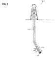
FIG. 1 illustrates an example system in which the embodiments of the supercapacitor device may be implemented in a borehole. -
FIG. 2 is a cross-sectional schematic view of an embodiment of a high temperature supercapacitor cell of the present disclosure. -
FIG. 3 is a plot of the voltammetric response of a supercapacitor utilizing an ionic liquid electrolyte composed of hexyltriethylammonium cations and bis(trifluoromethylsulfonyl)imide anions operating over a 4V range at 220 °C. -
FIG. 4 is a plot of the voltammetric response of ferrocene in gelled triethylsulfonium bis(trifluoromethylsulfonyl)imide. - In the following detailed description of embodiments, numerous specific details are set forth in order to provide a more thorough understanding. However, it will be apparent to one of ordinary skill in the art that embodiments may be practiced without these specific details. In other instances, well-known features have not been described in detail to avoid unnecessarily complicating the description.
- Embodiments of the present disclosure are related to high temperature supercapacitors as well as methods of making and using such supercapacitors. Particular embodiments may involve the use of such supercapacitors in a downhole environment to provide a power source to downhole tools. In one or more embodiments the present disclosure is directed to the electrolyte components used in such supercapacitors that may allow for use at wide operating conditions, including high pressure and high temperature downhole environments as well as room temperature environments.
- Referring to
FIG. 2 , a schematic cross-sectional view of a supercapacitor cell according to one or more embodiments is shown. A supercapacitor device includes at least one supercapacitor cell (211), as shown inFIG. 2 , disposed within a housing (not shown). A single supercapacitor cell (211) of a particular embodiment may include two working electrode layers (212) which are separated by an electrode separator (214). The separator is designed to prevent electrical short circuits whilst allowing the transport of ionic species between either electrode. The working electrode layers (212) are electrically connected to current collectors (216), which are supported upon inert substrate layers (218). The current collectors (216) may be physically protected from the environment of the working electrode layers (212) by electrolyte-impervious layers (220). Further, the supercapacitor cell (211) may include an electrolyte dispersed throughout the working layers and electrode separator (214). In operation, a current is passed between the working electrodes to polarize them either positively or negatively. In response, the ionic species within the electrolyte migrate towards the oppositely charged electrodes, charging the capacitor. Each of these components will be addressed in turn. - In one or more embodiments, the working electrode layers (212) may comprise a porous carbonaceous material applied as a layer on the conducting layer (current collector). As used herein, porous refers to a material having a large specific surface area (greater than 300 m2 g-1), which is accessible via a network of pores which may contain any combination of large micropores (1-2 nm diameter), mesopores (2-50 nm diameter), and/or small macropores (50-500 nm). Thus, in one or more embodiments, the specific surface area may be about 1900 m2 g-1. Further, the thickness of the working electrode may generally range from 1 µm - 2000 µm. In general, the amount of energy stored in a single supercapacitor cell is proportional to the accessible surface area of the porous carbonaceous material. Hence, maximization of the interfacial area between the working electrodes and the electrolyte is a desirable design feature. In one or more embodiments, the porous carbonaceous material may include activated carbon, carbon black, carbon nanotubes, graphene and its derivatives, carbon aerogels, or combinations thereof. In one or more embodiments, the porous material chosen for pairs of working electrodes may have identical composition; however, the present disclosure is not so limited.
- An electrode separator (214) may be inserted between the working electrodes (212) in order to prevent electrical short circuits whilst allowing the transport of ionic species between the supercapacitor cell compartments. In one or more particular embodiments, the electrode separator (214) should possess sufficient porosity to allow for efficient electrolyte transport between the working electrodes (212). In one or more embodiments, the electrode separator may include glass fibers or other non-conducting fibers. The fibers may have a fiber diameter in the range 1-20 micrometers and an average fiber length of at least 5 millimeters. They may be in the form of woven material, compressed matting, or glass wool. In one or more embodiments, they should have high electrolyte retention, high tensile strength, good shape recovery, and be chemically inert. Other non-conducting fibers which are stable at temperatures above 125°C and capable of being used in certain embodiments include alumina, mullite, silicon carbide, and zirconia.
- The working electrode layers (212) are electrically connected to the current collectors (216). In one or more embodiments, the current collectors (216) may include a conducting material such as carbon, aluminum, gold, silver, copper, or mixtures thereof. Each current collector (216), while electrically connected to a working electrode layer (216), may also be adjacent to an electrolyte-impervious layer (220) which protects the current collector (216) from chemical reaction with the electrolyte solution. In one or more embodiments, the electrolyte-impervious layer may comprise a substantially non-porous carbonaceous composite material or other substantially non-porous inert material, which may be physically distinct from the current collectors (216).
- The current collector (216) is supported by an inert substrate (218) which forms the outer layer of the supercapacitor cell (211). The inert substrate (218) may comprise any inert material suitable to withstand downhole conditions of high temperature and pressure. In more particular embodiments, the inert substrate may be a glassy or polymeric material. No limitation on the type of inert substrate exists, but any material that can provide the physical structure on which the supercapacitor cell layers may be formed is within the scope of the present disclosure.
- Dispersed throughout the internal space of the supercapacitor cell is the electrolyte. In one or more embodiments, the electrolyte is an inert ionic liquid or continuous phase of inert ionic liquid. In more particular embodiments, the electrolyte is an inert ionic liquid with at least one cationic component with an asymmetric arrangement of substituents bonded to at least one central cationic component. In yet a more particular embodiment, the asymmetric arrangement of substituents is generated by incorporating substituents of diverse sizes.
- In a yet more particular embodiment, the cationic component has the generic formula (Rx ) n Z + where Z + is the ammonium, phosphonium, or sulfonium cation, the Rx substituents are linear or branched alkyl groups comprising 1-12 carbon atoms and may be the same alkyl group or different alkyl groups, n = 4 for the ammonium and phosphonium cations, and n = 3 for the sulfonium cation. In a yet more particular embodiment, at least one alkyl group has a different size relative to the others. This guarantees the asymmetric nature of the cation. For example, in one or more embodiments, at least one alkyl group may range from C1-C3, while at least one alkyl group may be greater than C4. In general, increasing the asymmetry of the cation decreases the melting point of the ionic liquid, and thus substantially extends the range of operating temperatures in both above-ground and downhole situations. Further, increasing the size of the substituent groups also diminishes the probability of electron tunneling and protects the cation from electron transfer, which allows the supercapacitor device to function over a wider voltage stability window.
- In particular embodiments, the ionic liquid electrolyte may include hexyltriethylammonium cations and/or butyltrimethylammonium cations paired with bis(trifluoromethylsulfonyl)imide anions, the chemical structures of which are shown below.
-

-

-

- In one or more embodiments, the ionic liquid may constitute substantially the entire electrolyte phase or at least a substantial portion of the electrolyte phase. In other embodiments, the ionic liquid may provide the conducting component of the electrolyte solution in the presence of either aqueous or non-aqueous diluents. Typical non-aqueous diluents include alcohols, nitriles, dimethylacetamide, dimethylformamide, and dimethyl sulfoxide. These diluents may be present in any ratio by volume.
- In one or more embodiments, the ionic liquid electrolyte phase may further include a viscosifier added thereto to modify the viscosity of the electrolyte to substantially immobilize the ionic liquid electrolyte (so that the liquid does not undergo convective flow into undesired locations) but still allows for internal diffusion of the ions therein. In one or more embodiments, the viscosifier may include a silica gellant. In more particular embodiments, the silica gellant may be added to the ionic liquid electrolyte in an amount from about 1 to 15 weight % of the total weight of the electrolyte phase. In more particular embodiments, the silica gellant may be added to the ionic liquid electrolyte in an amount from about 3 to 10 weight % of the total weight of the electrolyte phase, or from 6 to 8 weight % of the total weight in yet other embodiments. In a further embodiment, the silica gellant is a fumed silica with either hydrophobic or hydrophilic characteristics and a BET surface area of greater than 300 m2 g-1.
- The supercapacitor cell as described above may be fabricated using any means known in the art, with no limitation. Generally, the component layers included in the supercapacitor cell may be applied or deposited sequentially onto the preceding layer until the structure as described above is generated.
- In more particular embodiments, a plurality of supercapacitor cells as described in the embodiments above may further be connected in series to achieve a greater voltage. Alternatively, a plurality of supercapacitor cells as described in the embodiments above may be connected in parallel to achieve a greater capacitance.
- The housing (not shown) may be a steel can in which at least one supercapacitor cell is deposited. The particular material used to form the housing does not limit the scope of the present disclosure. Rather, one skilled in the art will appreciate that the housing may be selected to be sufficiently capable of withstanding the high G-forces, temperatures, pressures, and corrosive environment experienced downhole within the wellbore. Alternative housing compositions may employ titanium, carbon reinforced alloys, and any other alloys, solid solutions or intermetallics that can retain structural integrity within the downhole environment. Further, it is also within the scope of the present disclosure that one or more components may be used to form the housing (not shown) including separate end pieces such as base plates (not shown) attached to the inert substrate layers. One skilled in the art would appreciate that separate end pieces (at both ends of the cell) may be desired for manufacturing ease. When multiple pieces are used to form the housing, one of ordinary skill in the art would appreciate that a hermetic seal may be formed between the multiple components. The supercapacitor cell structure disclosed above may be included in any fashion within the housing. That is, the supercapacitor cell or plurality of connected supercapacitor cells may be rolled, folded, or stacked into cylindrical or rectangular shapes within the housing.
- In general, some embodiments are related to methods of charging/recharging and/or discharging a supercapacitor device in oilfield applications. As illustrated in
FIG. 1 , a drilling system (100) includes a bottom hole assembly (102) connected at the bottom end of a drill string (101) suspended within a wellbore. The bottom hole assembly (102) may include a drill bit (104) at the lowermost end of the bottom hole assembly (102), a drill collar (106), and a motor (108). One or more other downhole tools may be located anywhere along the drill string (101) or along a wireline (not shown) in the wellbore when the drill string (101) and bottom hole assembly (102) are removed from the well. Further, in accordance with one or more embodiments, a supercapacitor device (105) may be located along the drill string (101) or on a wireline (not shown) and thus any tubular string in a drilling system, and may be electrically connected to any downhole tool, such as a MWD, LWD, sensor, or other actuable tool needing a power source to provide power thereto.. In particular embodiments, the supercapacitor device may be electrically connected to a component of motor (108) to receive energy therefrom so that the supercapacitor device may be charged while downhole. It should be understood that no limitation is intended by the arrangement of the drilling system, including the presence of absence of one or more components. As mentioned above, it is also envisioned that the drill string (101) may also be replaced by structures such as a wireline or any other apparatuses to convey the supercapacitor device (105) into the wellbore, where the supercapacitor device is electrically connected to one or more tools located on the wireline. When electrically connected to one or more tools, including sensors and/or other downhole tools, the supercapacitor device provides electrical power required for operation to said tools. Further, in one or more embodiments, the supercapacitor device may be used in conjunction with a battery, and may be connected in series with said battery. - In this disclosure, components that are "electrically connected" are connected in such a way that electric current may flow between the components. Components that are electrically connected may include additional components that are connected between them. In addition, in some cases, a switch may be electrically connected to various components in a circuit. Even though a switch may be in an open position, which would break the circuit and prevent electrical flow, this does not prevent components from being electrically connected in accordance with the present disclosure. A switch is intended to be closed at certain times, and at those times, electrical current may flow between the components that are electrically connected.
- In general, in some embodiments, the supercapacitor device may be charged/recharged by a motor or turbine that generates energy from wellbore fluid flow therethrough. The mechanism involved in charging/recharging the supercapacitor device would simply be using the energy generated by the motor or turbine to pass a current to the working electrodes as is required to charge the supercapacitor cells. It is also within the scope of the present disclosure that the supercapacitor device disclosed herein may be charged at the surface after being returned to the surface as well as being charged downhole during the drilling process, with no limitation on the particular method(s) that may be used for charging the supercapacitor device.
- A supercapacitor cell was constructed according to the abovementioned description. The two working electrode layers were formed from activated carbon. Each conducting layer was formed from silver metal. Separating each working electrode from its corresponding conducting layer was a layer of electrolyte-impervious smooth carbon. Glass was the inert substrate used. Glass fibers were used as the electrode separator material. The electrolyte utilized was an ionic liquid electrolyte composed of hexyltriethylammonium cations and bis(trifluoromethylsulfonyl)imide anions. The voltammetric response thereof was measured.
-
FIG. 3 shows a plot of the voltammetric response of the supercapacitor over a 4V range at 220 °C. From the plot it can be seen that the supercapacitor stably operates over many cycles at high temperature and over a wide voltage range (4V). This experiment was terminated arbitrarily after 100 cycles. - Ionic liquid gels were formed by the addition of fumed silica (Sigma-Aldrich, Product No. S5130) to various ionic liquids. The ionic liquids used were either triethylsulfonium bis(trifluoromethylsulfonyl)imide, hexyltriethylammonium bis(trifluoromethylsulfonyl)imide, or butyltrimethylammonium bis(trifluoromethylsulfonyl)imide. The amount of fumed silica mechanically dispersed into the ionic liquid was either 7.5 weight % of the total weight of the electrolyte phase. In some cases, the amount of fumed silica was doubled and ferrocene (10 mM) was added as a redox-active test reagent.
-
FIG. 4 shows a plot of the voltammetry of the ferrocene in triethylsulfonium bis(trifluoromethylsulfonyl)imide containing no silica, hydrophilic silica nanoparticles (S5130) in the amount of 7.5 weight % of the total weight of the electrolyte phase, and hydrophilic silica nanoparticles (S5130) in the amount of 15 weight % of the total weight of the electrolyte phase. Voltammetry was recorded using a RAM™ electrode (770 carbon microdisks, each of 7 µm diameter). The counter electrode was platinum gauze (A = 4.0 cm2). The potential was cycled from -0.25 V to +0.75 V to -0.25 V at 20 mV s-1. Scans were recorded at 25 °C following 30 seconds conditioning at -0.25 V vs Ag|AgCl. Shown inFIG. 4 are the first scans. For each scan, 3277 data points were collected and smoothed using a 21-point moving average to diminish mains interference. - It can be seen from
FIG. 4 that a small decrease in the voltammetric limiting current was observed as the amount of fumed silica in the gel was increased. However, the decrease was roughly in proportion to the volume fraction of silica suspended in the ionic liquid. This indicates that the internal diffusion of ions is not being inhibited by the silica particles, other than in proportion to the volume fraction unoccupied by silica. The same effect was found for the other ionic liquid electrolytes tested and when using both the hydrophilic and hydrophobic fumed silica gels on both the glassy carbon and the RAM electrodes, suggesting that the lack of diffusion inhibition by the silica particles is a general property of ionic-liquid/fumed silica gels. This result demonstrates that ionic liquids can maintain their electrolyte performance even after gelling. - Embodiments of the present disclosure may provide at least one of the following advantages. For example, the ionic liquid electrolytes used in the electric double layer capacitor may advantageously allow, due to their inherently low vapor pressure, for a supercapacitor to be operable at the high temperature ranges (20°C to 220°C) and pressures, which are experienced in a downhole environment. Additionally, the asymmetric alkyl cations allow the supercapacitor to function successfully over a wide voltage range (0 to 4 volts).
- While the invention has been described with respect to a limited number of embodiments, those skilled in the art, having benefit of this disclosure, will appreciate that other embodiments can be devised which do not depart from the scope of the invention as disclosed herein. Accordingly, the scope should be limited by the attached claims. It is the express intention of the applicant not to invoke 35 U.S.C. §112, paragraph 6 for any limitations of any of the claims herein, except for those in which the claim expressly uses the words 'means for' together with an associated function.
Claims (7)
- A supercapacitor device, comprising:a housing; andat least one supercapacitor cell disposed in the housing, the supercapacitor cell comprising:two working electrode layers separated by an electrode separator wherein each working electrode layer is electrically connected to a current collector supported upon an inert substrate layer;an electrolyte-impervious layer disposed between each working electrode layer and each current collector; andan electrolyte disposed within the area occupied by the working electrode layers and the electrode separator, the electrolyte comprising a continuous phase of an inert ionic liquid.
- The supercapacitor device of claim 1, wherein a cationic component of the inert ionic liquid has sufficiently large alkyl group substituents that the probability of electron tunneling is diminished.
- The supercapacitor device of claim 1, wherein the continuous phase of inert ionic liquid is comprised of at least one substituted central cation.
- The supercapacitor device of claim 3, wherein the at least one substituted central cation is substituted by linear or branched alkyl groups comprising from 1-12 carbons.
- The supercapacitor device of claim 1, wherein the inert ionic liquid comprises hexyltriethylammonium cations and/or butyltrimethylammonium cations paired with bis(trifluoromethylsulfonyl)imide anions.
- The supercapacitor device of claim 1, further comprising a silica gellant added to the inert ionic liquid in the amount from about 1 to 15 wt % of the total weight of the electrolyte phase.
- The supercapacitor device of claim 1, further comprising an aqueous or non-aqueous diluent added to the inert ionic liquid.
Applications Claiming Priority (3)
| Application Number | Priority Date | Filing Date | Title |
|---|---|---|---|
| US201261662451P | 2012-06-21 | 2012-06-21 | |
| US13/923,059 US9318271B2 (en) | 2012-06-21 | 2013-06-20 | High temperature supercapacitor |
| EP13806254.2A EP2864571B1 (en) | 2012-06-21 | 2013-06-21 | High temperature supercapacitor |
Related Parent Applications (2)
| Application Number | Title | Priority Date | Filing Date |
|---|---|---|---|
| EP13806254.2A Division EP2864571B1 (en) | 2012-06-21 | 2013-06-21 | High temperature supercapacitor |
| EP13806254.2A Division-Into EP2864571B1 (en) | 2012-06-21 | 2013-06-21 | High temperature supercapacitor |
Publications (1)
| Publication Number | Publication Date |
|---|---|
| EP2958121A1 true EP2958121A1 (en) | 2015-12-23 |
Family
ID=49769422
Family Applications (2)
| Application Number | Title | Priority Date | Filing Date |
|---|---|---|---|
| EP13806254.2A Not-in-force EP2864571B1 (en) | 2012-06-21 | 2013-06-21 | High temperature supercapacitor |
| EP15178281.0A Withdrawn EP2958121A1 (en) | 2012-06-21 | 2013-06-21 | High temperature and pression resistant supercapacitor |
Family Applications Before (1)
| Application Number | Title | Priority Date | Filing Date |
|---|---|---|---|
| EP13806254.2A Not-in-force EP2864571B1 (en) | 2012-06-21 | 2013-06-21 | High temperature supercapacitor |
Country Status (6)
| Country | Link |
|---|---|
| US (1) | US9318271B2 (en) |
| EP (2) | EP2864571B1 (en) |
| CN (1) | CN104321500B (en) |
| BR (1) | BR112014030548A2 (en) |
| MY (1) | MY180440A (en) |
| WO (1) | WO2013192518A1 (en) |
Families Citing this family (36)
| Publication number | Priority date | Publication date | Assignee | Title |
|---|---|---|---|---|
| US20120116381A1 (en) | 2010-11-05 | 2012-05-10 | Houser Kevin L | Surgical instrument with charging station and wireless communication |
| US9375255B2 (en) | 2010-11-05 | 2016-06-28 | Ethicon Endo-Surgery, Llc | Surgical instrument handpiece with resiliently biased coupling to modular shaft and end effector |
| US9510895B2 (en) | 2010-11-05 | 2016-12-06 | Ethicon Endo-Surgery, Llc | Surgical instrument with modular shaft and end effector |
| US9782214B2 (en) | 2010-11-05 | 2017-10-10 | Ethicon Llc | Surgical instrument with sensor and powered control |
| US10959769B2 (en) | 2010-11-05 | 2021-03-30 | Ethicon Llc | Surgical instrument with slip ring assembly to power ultrasonic transducer |
| US9782215B2 (en) | 2010-11-05 | 2017-10-10 | Ethicon Endo-Surgery, Llc | Surgical instrument with ultrasonic transducer having integral switches |
| US10085792B2 (en) | 2010-11-05 | 2018-10-02 | Ethicon Llc | Surgical instrument with motorized attachment feature |
| US9381058B2 (en) | 2010-11-05 | 2016-07-05 | Ethicon Endo-Surgery, Llc | Recharge system for medical devices |
| US10660695B2 (en) | 2010-11-05 | 2020-05-26 | Ethicon Llc | Sterile medical instrument charging device |
| US10881448B2 (en) | 2010-11-05 | 2021-01-05 | Ethicon Llc | Cam driven coupling between ultrasonic transducer and waveguide in surgical instrument |
| US20120116265A1 (en) * | 2010-11-05 | 2012-05-10 | Houser Kevin L | Surgical instrument with charging devices |
| US9597143B2 (en) | 2010-11-05 | 2017-03-21 | Ethicon Endo-Surgery, Llc | Sterile medical instrument charging device |
| US9072523B2 (en) | 2010-11-05 | 2015-07-07 | Ethicon Endo-Surgery, Inc. | Medical device with feature for sterile acceptance of non-sterile reusable component |
| US9421062B2 (en) | 2010-11-05 | 2016-08-23 | Ethicon Endo-Surgery, Llc | Surgical instrument shaft with resiliently biased coupling to handpiece |
| US9558894B2 (en) | 2011-07-08 | 2017-01-31 | Fastcap Systems Corporation | Advanced electrolyte systems and their use in energy storage devices |
| CN104221110B (en) | 2011-07-08 | 2019-04-05 | 快帽系统公司 | High temperature energy storage device |
| US9406442B2 (en) | 2012-03-22 | 2016-08-02 | California Institute Of Technology | Micro- and nanoscale capacitors that incorporate an array of conductive elements having elongated bodies |
| SG11201509147TA (en) | 2013-06-10 | 2015-12-30 | California Inst Of Techn | Systems and methods for implementing high-temperature tolerant supercapacitors |
| US10872737B2 (en) | 2013-10-09 | 2020-12-22 | Fastcap Systems Corporation | Advanced electrolytes for high temperature energy storage device |
| EP3007266B1 (en) * | 2014-10-07 | 2017-09-06 | Nokia Technologies OY | An apparatus and associated methods for electrical storage |
| US10136938B2 (en) | 2014-10-29 | 2018-11-27 | Ethicon Llc | Electrosurgical instrument with sensor |
| WO2016204820A2 (en) | 2015-01-27 | 2016-12-22 | Fastcap Systems Corporation | Wide temperature range ultracapacitor |
| KR102469677B1 (en) | 2015-01-27 | 2022-11-22 | 패스트캡 시스템즈 코포레이션 | Wide temperature range ultracapacitors |
| MY194849A (en) | 2016-05-20 | 2022-12-19 | Kyocera Avx Components Corp | Ultracapacitor for use at high temperatures |
| WO2018102652A1 (en) | 2016-12-02 | 2018-06-07 | Fastcap Systems Corporation | Composite electrode |
| IT201800004596A1 (en) | 2018-04-17 | 2019-10-17 | ENERGY STORAGE DEVICE FOR HIGH TEMPERATURE APPLICATIONS | |
| WO2023102265A1 (en) | 2021-12-03 | 2023-06-08 | Sustainable Energy Technologies, Inc. | System and method for energy management of a power pack for an electric vehicle including photovoltaic charging |
| US12179608B2 (en) | 2021-12-03 | 2024-12-31 | Sustainable Energy Technologies, Inc. | Monitoring and managing temperature of power packs |
| US12194886B2 (en) | 2021-12-06 | 2025-01-14 | Sustainable Energy Technologies, Inc. | System and method for analyzing temperature changes in supercapacitor battery storage for electric vehicle |
| US12296721B2 (en) | 2021-12-10 | 2025-05-13 | Sustainable Energy Technologies, Inc. | Method and systems to trickle charge electric vehicle's supercapacitors using solar energy |
| US12224611B2 (en) | 2021-12-14 | 2025-02-11 | Sustainable Energy Technologies, Inc. | Supercapacitor to electrochemical hybrid system |
| WO2023114429A1 (en) | 2021-12-17 | 2023-06-22 | Sustainable Energy Technologies, Inc. | Intelligent hybrid power system for electrical vehicles |
| US12533968B2 (en) | 2021-12-30 | 2026-01-27 | Sustainable Energy Technologies, Inc. | Supercapacitor to electrochemical hybrid system with failsafe safety capability |
| WO2023129614A1 (en) | 2021-12-30 | 2023-07-06 | Sustainable Energy Technologies, Inc. | Supercapacitor to electrochemical hybrid system with smart self-discharge capability |
| WO2023129616A1 (en) | 2021-12-30 | 2023-07-06 | Sustainable Energy Technologies, Inc. | Supercapacitor to electrochemical hybrid system with a supercapacitor battery management capability |
| US12224576B2 (en) | 2023-03-08 | 2025-02-11 | Championx Llc | Protection circuitry for a downhole measurement tool |
Citations (2)
| Publication number | Priority date | Publication date | Assignee | Title |
|---|---|---|---|---|
| US20110204020A1 (en) * | 2010-02-19 | 2011-08-25 | Nthdegree Technologies Worldwide Inc. | Method of and Printable Compositions for Manufacturing a Multilayer Carbon Nanotube Capacitor |
| WO2012056050A2 (en) * | 2010-10-31 | 2012-05-03 | OÜ Skeleton Technologies | An electrical double layer capacitor with enhanced working voltage |
Family Cites Families (24)
| Publication number | Priority date | Publication date | Assignee | Title |
|---|---|---|---|---|
| JP3070408B2 (en) * | 1993-12-28 | 2000-07-31 | 日本電気株式会社 | Solid electrolytic capacitor and method of manufacturing the same |
| US6517892B1 (en) * | 1999-05-24 | 2003-02-11 | Showa Denko K.K. | Solid electrolytic capacitor and method for producing the same |
| KR100487069B1 (en) | 2000-04-12 | 2005-05-03 | 일진나노텍 주식회사 | Supercapacitor using electrode of new material and manufacturing method the same |
| JP3941917B2 (en) * | 2001-10-19 | 2007-07-11 | Necトーキン株式会社 | Electric double layer capacitor manufacturing method and electric double layer capacitor |
| BR0305630A (en) | 2002-06-21 | 2004-11-30 | Univ California | Electrolyte solution for electro-optical devices comprising ionic liquids, electro-optical device, compound and method for filling an electro-optical device |
| JP2004289130A (en) * | 2003-03-04 | 2004-10-14 | Jeol Ltd | Electric double layer capacitor |
| US20100239916A1 (en) | 2003-08-08 | 2010-09-23 | Max-Planck-Gesellschaft Zur Forderung Der Wissenschaften E.V. | Non-aqueous electrolyte and a battery, a supercapacitor, an electrochromic device and a solar cell including such an electrolyte |
| CN100399480C (en) | 2003-09-30 | 2008-07-02 | 清华大学深圳研究生院 | Method for manufacturing laminated supercapacitor |
| US7553341B2 (en) | 2004-11-24 | 2009-06-30 | The Regents Of The University Of California | High power density supercapacitors with carbon nanotube electrodes |
| US7493962B2 (en) | 2004-12-14 | 2009-02-24 | Schlumberger Technology Corporation | Control line telemetry |
| WO2006117872A1 (en) * | 2005-04-28 | 2006-11-09 | Kanto Denka Kogyo Co., Ltd. | Ionic fluid containing phosphonium cation and process for producing the same |
| JP3872494B1 (en) | 2005-08-23 | 2007-01-24 | 株式会社パワーシステム | Winding type electric double layer capacitor |
| EP1970990B1 (en) * | 2005-12-26 | 2013-04-17 | Bridgestone Corporation | Non-aqueous electrolyte solution for battery, non-aqueous electrolyte battery comprising the same, electrolyte solution for electric double layer capacitor and electric double layer capacitor comprising the same |
| GB0607957D0 (en) | 2006-04-21 | 2006-05-31 | Imp Innovations Ltd | Energy storage device |
| DE102006023649A1 (en) * | 2006-05-17 | 2008-01-03 | Philipps-Universität Marburg | Hydrophobic ionic liquids |
| JP2008182182A (en) | 2006-12-28 | 2008-08-07 | Power System:Kk | Non-porous carbon with charging curve indicative of sharp bend and electric double-layer capacitor |
| JP5242973B2 (en) * | 2007-08-23 | 2013-07-24 | 日本化学工業株式会社 | Electrolyte composition for electricity storage device and electricity storage device using the same |
| US7948739B2 (en) | 2007-08-27 | 2011-05-24 | Nanotek Instruments, Inc. | Graphite-carbon composite electrode for supercapacitors |
| CA2625271A1 (en) | 2008-03-11 | 2009-09-11 | Hydro-Quebec | Method for preparing an electrochemical cell having a gel electrolyte |
| US7903390B2 (en) | 2008-06-19 | 2011-03-08 | Gas Technology Institute | Bipolar membrane for electrochemical supercapacitors and other capacitors |
| US8149552B1 (en) * | 2008-06-30 | 2012-04-03 | Automation Solutions, LLC | Downhole measurement tool circuit and method to balance fault current in a protective inductor |
| US8907133B2 (en) * | 2008-07-14 | 2014-12-09 | Esionic Es, Inc. | Electrolyte compositions and electrochemical double layer capacitors formed there from |
| US8213157B2 (en) | 2009-04-17 | 2012-07-03 | University Of Delaware | Single-wall carbon nanotube supercapacitor |
| US8760851B2 (en) * | 2010-12-21 | 2014-06-24 | Fastcap Systems Corporation | Electrochemical double-layer capacitor for high temperature applications |
-
2013
- 2013-06-20 US US13/923,059 patent/US9318271B2/en not_active Expired - Fee Related
- 2013-06-21 EP EP13806254.2A patent/EP2864571B1/en not_active Not-in-force
- 2013-06-21 WO PCT/US2013/047036 patent/WO2013192518A1/en not_active Ceased
- 2013-06-21 BR BR112014030548A patent/BR112014030548A2/en not_active IP Right Cessation
- 2013-06-21 EP EP15178281.0A patent/EP2958121A1/en not_active Withdrawn
- 2013-06-21 MY MYPI2014702840A patent/MY180440A/en unknown
- 2013-06-21 CN CN201380025129.1A patent/CN104321500B/en not_active Expired - Fee Related
Patent Citations (2)
| Publication number | Priority date | Publication date | Assignee | Title |
|---|---|---|---|---|
| US20110204020A1 (en) * | 2010-02-19 | 2011-08-25 | Nthdegree Technologies Worldwide Inc. | Method of and Printable Compositions for Manufacturing a Multilayer Carbon Nanotube Capacitor |
| WO2012056050A2 (en) * | 2010-10-31 | 2012-05-03 | OÜ Skeleton Technologies | An electrical double layer capacitor with enhanced working voltage |
Also Published As
| Publication number | Publication date |
|---|---|
| BR112014030548A2 (en) | 2017-06-27 |
| EP2864571A1 (en) | 2015-04-29 |
| CN104321500A (en) | 2015-01-28 |
| CN104321500B (en) | 2017-06-23 |
| WO2013192518A1 (en) | 2013-12-27 |
| EP2864571B1 (en) | 2016-12-28 |
| US9318271B2 (en) | 2016-04-19 |
| MY180440A (en) | 2020-11-28 |
| EP2864571A4 (en) | 2016-01-06 |
| US20130342962A1 (en) | 2013-12-26 |
Similar Documents
| Publication | Publication Date | Title |
|---|---|---|
| EP2864571B1 (en) | High temperature supercapacitor | |
| JP7002481B2 (en) | Modular signal interface equipment and related wells power and data systems | |
| US20250179895A1 (en) | Production logging instrument | |
| Sun et al. | A capacity recoverable zinc-ion micro-supercapacitor | |
| Zhang et al. | Functionalized carbonaceous fibers for high performance flexible all-solid-state asymmetric supercapacitors | |
| EP3251133B1 (en) | Wide operating temperature range (0° to 275°c) ultracapacitor | |
| Yang et al. | Freestanding lamellar porous carbon stacks for low‐temperature‐foldable supercapacitors | |
| Aldama et al. | Contribution of cations and anions of aqueous electrolytes to the charge stored at the electric electrolyte/electrode interface of carbon-based supercapacitors | |
| KR101891063B1 (en) | Electric double layer capacitor | |
| JP2016521451A5 (en) | ||
| EP2933229A1 (en) | Electrochemical capacitor devices using two-dimensional carbon material for high frequency AC line filtering | |
| WO2015196052A1 (en) | Lubricant-impregnated surfaces for electrochemical applications, and devices and systems using same | |
| US20140315096A1 (en) | Clay- based energy storage compositions for high temperature applications | |
| US20160099474A1 (en) | Electrochemical Devices For Use In Extreme Conditions | |
| US20150140378A1 (en) | Molten salt battery and power supply system | |
| WO2008009975A2 (en) | Method for selecting salts of electrolytes for double layers capacitors | |
| US9553336B2 (en) | Power supply system for well | |
| KR20240023712A (en) | Interconnect strip for an ultracapacitor module | |
| KR20200026796A (en) | Energy storage devices | |
| Chand | Role of Aqueous Electrolytes in the Performance of Electrochemical Supercapacitors | |
| US20250316420A1 (en) | System and method for forming capacitors in wellbores |
Legal Events
| Date | Code | Title | Description |
|---|---|---|---|
| PUAI | Public reference made under article 153(3) epc to a published international application that has entered the european phase |
Free format text: ORIGINAL CODE: 0009012 |
|
| 17P | Request for examination filed |
Effective date: 20150724 |
|
| AC | Divisional application: reference to earlier application |
Ref document number: 2864571 Country of ref document: EP Kind code of ref document: P |
|
| AK | Designated contracting states |
Kind code of ref document: A1 Designated state(s): AL AT BE BG CH CY CZ DE DK EE ES FI FR GB GR HR HU IE IS IT LI LT LU LV MC MK MT NL NO PL PT RO RS SE SI SK SM TR |
|
| AX | Request for extension of the european patent |
Extension state: BA ME |
|
| 17Q | First examination report despatched |
Effective date: 20180912 |
|
| STAA | Information on the status of an ep patent application or granted ep patent |
Free format text: STATUS: THE APPLICATION IS DEEMED TO BE WITHDRAWN |
|
| 18D | Application deemed to be withdrawn |
Effective date: 20190323 |