EP2958117B1 - A foil transformer - Google Patents
A foil transformer Download PDFInfo
- Publication number
- EP2958117B1 EP2958117B1 EP15171379.9A EP15171379A EP2958117B1 EP 2958117 B1 EP2958117 B1 EP 2958117B1 EP 15171379 A EP15171379 A EP 15171379A EP 2958117 B1 EP2958117 B1 EP 2958117B1
- Authority
- EP
- European Patent Office
- Prior art keywords
- foil
- winding portions
- strips
- winding
- magnetic axis
- Prior art date
- Legal status (The legal status is an assumption and is not a legal conclusion. Google has not performed a legal analysis and makes no representation as to the accuracy of the status listed.)
- Active
Links
Images


Classifications
-
- H—ELECTRICITY
- H01—ELECTRIC ELEMENTS
- H01F—MAGNETS; INDUCTANCES; TRANSFORMERS; SELECTION OF MATERIALS FOR THEIR MAGNETIC PROPERTIES
- H01F27/00—Details of transformers or inductances, in general
- H01F27/28—Coils; Windings; Conductive connections
- H01F27/2847—Sheets; Strips
- H01F27/2852—Construction of conductive connections, of leads
-
- H—ELECTRICITY
- H01—ELECTRIC ELEMENTS
- H01F—MAGNETS; INDUCTANCES; TRANSFORMERS; SELECTION OF MATERIALS FOR THEIR MAGNETIC PROPERTIES
- H01F27/00—Details of transformers or inductances, in general
- H01F27/24—Magnetic cores
-
- H—ELECTRICITY
- H01—ELECTRIC ELEMENTS
- H01F—MAGNETS; INDUCTANCES; TRANSFORMERS; SELECTION OF MATERIALS FOR THEIR MAGNETIC PROPERTIES
- H01F27/00—Details of transformers or inductances, in general
- H01F27/28—Coils; Windings; Conductive connections
- H01F27/30—Fastening or clamping coils, windings, or parts thereof together; Fastening or mounting coils or windings on core, casing, or other support
- H01F27/303—Clamping coils, windings or parts thereof together
-
- H—ELECTRICITY
- H01—ELECTRIC ELEMENTS
- H01F—MAGNETS; INDUCTANCES; TRANSFORMERS; SELECTION OF MATERIALS FOR THEIR MAGNETIC PROPERTIES
- H01F27/00—Details of transformers or inductances, in general
- H01F27/28—Coils; Windings; Conductive connections
- H01F27/30—Fastening or clamping coils, windings, or parts thereof together; Fastening or mounting coils or windings on core, casing, or other support
- H01F27/306—Fastening or mounting coils or windings on core, casing or other support
-
- H—ELECTRICITY
- H01—ELECTRIC ELEMENTS
- H01F—MAGNETS; INDUCTANCES; TRANSFORMERS; SELECTION OF MATERIALS FOR THEIR MAGNETIC PROPERTIES
- H01F27/00—Details of transformers or inductances, in general
- H01F27/34—Special means for preventing or reducing unwanted electric or magnetic effects, e.g. no-load losses, reactive currents, harmonics, oscillations, leakage fields
-
- H—ELECTRICITY
- H01—ELECTRIC ELEMENTS
- H01F—MAGNETS; INDUCTANCES; TRANSFORMERS; SELECTION OF MATERIALS FOR THEIR MAGNETIC PROPERTIES
- H01F27/00—Details of transformers or inductances, in general
- H01F27/28—Coils; Windings; Conductive connections
- H01F27/2847—Sheets; Strips
- H01F2027/2857—Coil formed from wound foil conductor
Definitions
- the invention relates generally to transformers. More particularly, the invention relates to a transformer having foil windings which have interleaved portions so as to reduce the leakage inductances of the foil windings.
- SMPS switched mode power supply
- the leakage inductance of the primary winding causes that all the energy charged to the transformer of the flyback power supply via the primary winding cannot be discharged from the transformer via the secondary winding.
- a known way to reduce the leakage inductances of windings of a transformer is to use interleaved windings where each winding comprises winding portions which are interleaved with corresponding winding portions of one or more other windings of the transformer.
- An inherent challenge related to interleaved windings is the need to arrange electrical connections between winding portions so as to connect the winding portions to constitute a winding.
- An electrical connection between two winding portions belonging to a same winding have to form a connection bridge over one or more other winding portions of one or more other windings where the one or more other winding portions are located, in the interleaving arrangement, between the two winding portions of the winding under consideration.
- the inductance of the above-mentioned electrical connection between the winding portions should be as small as possible in order to avoid weakening or even losing the advantage provided by the interleaved windings, i.e. the reduction of the leakage inductances.
- Foil windings are usual in transformers of many varieties and applications because of various advantages of the foil (see for instance the interleaved transformer foil windings in the inductor/capacitor device of US4327311 ).
- the skin effect does not reduce the effective electrically conductive area so strongly in a flat and thin foil conductor as e.g. in a round wire conductor having a same cross-sectional area.
- the above-presented challenge related to interleaved windings is present also in a case where foil windings of a transformer are configured to constitute interleaved windings, i.e. there is the need to arrange electrical connections between winding portions of each foil winding so that the inductances of the electrical connections are as small as possible.
- a transformer according to the invention comprises:
- the first winding portions are interleaved with the second winding portions in directions substantially perpendicular to the magnetic axis so as to reduce the leakage inductances of the first and second foil windings.
- the first winding portions are electrically interconnected so that:
- the number of the second winding portions is at least two and the second winding portions are electrically interconnected so that:
- each electrical connection between two winding portions comprises two connection bridges because the interconnected end-portions of the foil conductors are each split to constitute two strips folded to mutually opposite directions. This reduces the inductances of the above-mentioned electrical connections because the two connection bridges are substantially parallel connected.
- the electrical connections can be configured to further symmetry in the distributions of currents flowing in the foil conductors because the electrical connections can be made symmetric with respect to longitudinal symmetry lines of the foil conductors.
- a transformer according to an exemplifying and non-limiting embodiment of the invention further comprises at least one third foil winding having a substantially same magnetic axis as the first and second foil windings.
- the third foil winding may comprise two or more third winding portions which are interleaved with the first and second winding portions and which are electrically interconnected in the way described above.
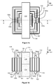
- Figure 1 a shows a perspective view of a transformer according to an exemplifying and non-limiting embodiment of the invention.
- Figure 1b shows a side-view of the transformer
- figure 1c shows a top-view of the transformer
- figure 1d shows a view of a section taken along a line A-A shown in figure 1c .
- the section plane is parallel with the xz-plane of a coordinate system 199.
- the transformer comprises a first foil winding which can be connected to an external electrical system via connection terminals 109 and 110, and a second foil winding which can be connected to the external electrical system via connection terminals 111 and 112.
- the magnetic axis of the first foil winding is substantially the same as the magnetic axis of the second foil winding and parallel with the z-axis of the coordinate system 199.
- the transformer can be, for example but not necessarily, a transformer of a switched mode power supply "SMPS" e.g. a flyback power supply or a resonance converter.
- SMPS switched mode power supply
- the first foil winding may operate as a primary winding and the second foil winding may operate as secondary winding.
- the first foil winding of the transformer is comprised of first winding portions made of first foil conductors so that the lateral direction of the first foil conductors is parallel with the magnetic axis of the first and second foil windings, i.e. parallel with the z-axis of the coordinate system 199.
- the first winding portions are illustrated in figures 1c and 1d and they are denoted with reference numbers 101 and 102.
- the second foil winding of the transformer is comprised of second winding portions made of second foil conductors so that the lateral direction of the second foil conductors is parallel with the magnetic axis of the first and second foil windings, i.e. parallel with the z-axis of the coordinate system 199.
- the second winding portions are illustrated in figures 1c and 1d and they are denoted with reference numbers 103 and 104.
- the winding portions 101-104 are interleaved in the directions perpendicular to the z-axis of the coordinate system 199 so that the winding portion 101 is the innermost one, the winding portion 103 is between the winding portions 101 and 102, the winding portion 104 is the outermost one, and the winding portion 102 is between the winding portions 103 and 104.
- the above-presented interleaving arrangement is only an example and many different interleaving arrangements are possible.
- one of the foil windings e.g.
- the second foil winding can be comprised of only one winding portion which alone constitutes the foil winding under consideration and is located between the winding portions of the other foil winding.
- at least one of the foil windings may comprise more than two winding portions interleaved with the winding portions of the other foil winding.
- An end-portion of the foil conductor of the winding portion 101 is split to constitute two strips 105a and 105b which have been folded to mutually opposite directions substantially parallel with the z-axis of the coordinate system 199. This is illustrated in figure 1e where lines along which the strips 105a and 105b are folded are depicted with dashed lines.
- an end-portion of the foil conductor of the winding portion 102 is split to constitute two strips 106a and 106b which have been folded to mutually opposite directions substantially parallel with the z-axis
- an end-portion of the foil conductor of the winding portion 103 is split to constitute two strips 107a and 107b which have been folded to mutually opposite directions substantially parallel with the z-axis
- an end-portion of the foil conductor of the winding portion 104 is split to constitute two strips 108a and 108b which have been folded to mutually opposite directions substantially parallel with the z-axis.
- the ends of the strips 105a and 106a are interconnected to constitute a connection bridge over the winding portion 103 as illustrated in figure 1d .
- the ends of the strips 105a and 106a can be interconnected for example by soldering or using mechanical fastening means, e.g. a bolt and a nut.
- the ends of the strips 105b and 106b are interconnected to constitute another connection bridge over the winding portion 103.
- the ends of the strips 107a and 108a are interconnected to constitute a connection bridge over the winding portion 102 as illustrated in figure 1d .
- the ends of the strips 107b and 108b are interconnected to constitute another connection bridge over the winding portion 102.
- the winding portions 101 and 102 are electrically interconnected with the two connection bridges constituted by the ends of the strips 105a and 106a and by the ends of the strips 105b and 106b.
- the two-sided electrical connection formed by the two connection bridges furthers symmetry in the distribution of current flowing in the foil conductors of the winding portions 101 and 102.
- the above-mentioned is valid also for the winding portions 103 and 104.
- the exemplifying transformer illustrated in figures 1a-1e comprises a core structure 113 having a leg surrounded by the first and second foil windings, where the longitudinal direction of the leg is substantially parallel with the magnetic axis of the first and second foil windings, i.e. parallel with the z-axis of the coordinate system 199.
- the leg is denoted with a reference number 116 in figures 1a and 1d .
- Figure 1 a shows a part of the leg 116 and figure 1d shows a section view of the leg.
- the core structure 113 comprises ferromagnetic material.
- the core structure may comprise for example ferrite or a stack of ferromagnetic steel sheets. Interleaved foil windings of the kind described above are, however, also applicable in transformers which do not comprise a ferromagnetic core structure.
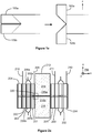
- FIG. 2a shows a section view of a transformer according to an exemplifying and non-limiting embodiment of the invention.
- the transformer comprises a first foil winding which can be connected to an external electrical system via connection terminals 209 and 210, and a second foil winding which can be connected to the external electrical system via connection terminals 211 and 212.
- the first and second foil windings have a substantially same magnetic axis which is parallel with the z-axis of a coordinate system 299.
- the first foil winding of the transformer is comprised of first winding portions 201 and 202 made of first foil conductors so that the lateral direction of the first foil conductors is parallel with the magnetic axis of the first and second foil windings.
- the second foil winding of the transformer is comprised of second winding portions 203 and 204 made of second foil conductors so that the lateral direction of the second foil conductors is parallel with the magnetic axis of the first and second foil windings.
- the winding portions 201-204 are interleaved in the directions perpendicular to the z-axis of the coordinate system 299 so that the winding portion 201 is the innermost one, the winding portion 203 is between the winding portions 201 and 202, the winding portion 204 is the outermost one, and the winding portion 202 is between the winding portions 203 and 204.
- the transformer comprises a ferromagnetic core structure 213 having a leg 216 surrounded by the first and second foil windings, where the longitudinal direction of the leg is substantially parallel with the magnetic axis of the first and second foil windings, i.e. parallel with the z-axis of the coordinate system 299.
- the leg comprises two parts 216a and 216b which are separated from each other in the longitudinal direction of the leg by a non-ferromagnetic gap.
- Figure 2b shows a magnification of a part 220 of figure 2a .
- the non-ferromagnetic gap is denoted with a reference number 217.
- Each foil conductor of the foil windings comprises two mutually parallel strips a distance apart from each other in the direction of the magnetic axis so that a gap 218 between the strips is aligned with the non-ferromagnetic gap 217 so as to hinder the spreading of magnetic flux 219 caused by the non-ferromagnetic gap 217 from inducing eddy currents in the foil conductors closest to the leg 216.
- the two mutually parallel strips of the foil conductor of the winding portion 201 are denoted with reference numbers 205a and 205b.
- Figure 2c illustrates how the strips are folded to two mutually opposite directions so that the ends of the strips can be connected to the ends of the corresponding strips 206a and 206b of the winding portion 202 as illustrated in figure 2a .
- the above-described reduction of eddy currents can be achieved also by arranging only a foil conductor portion which is a part of one of the foil conductors and which is closest to the leg 216 to have two mutually parallel strips a distance apart from each other in the direction of the magnetic axis, i.e. the z-axis, so that the gap between these strips is aligned with the non-ferromagnetic gap 217.
- all the foil conductors do not need to consist of two mutually parallel strips and even the whole foil conductor which is closest to the leg does not need to consist of two mutually parallel strips.
- the choice between different alternatives is dependent on e.g. manufacture related viewpoints.
- connection terminals 109-112 and 209-212 are single sided so that they protrude in the positive z-directions of the coordinate systems 199 and 299.
- the connection terminals can be constructed for example by folding the foil conductors to form a substantially right angle so that the folding line has an angle of 45 degrees with respect to the longitudinal direction of the foil conductor under consideration. It is also possible to have two-sided connection terminals which can be constructed in the way illustrated in figure 1e or in the way illustrated figure 2c depending on the case.
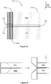
- FIG 3 illustrates a transformer system according to an exemplifying and non-limiting embodiment of the invention.
- the transformer system comprises a transformer 321 and first and second circuit boards 314 and 315.
- the circuit boards are parallel with the xy-plane of a coordinate system 399.
- the transformer can be for example such as the transformer illustrated in figures 1a-1e or the transformer illustrated in figures 2a-2c .
- each of the connection terminals of the transformer 321 is soldered to an electrical conductor of the circuit board 314.
- connection terminals and/or the ends of the strips can be threaded to through-holes of the circuit boards and thereafter soldered to the electrical conductors of the circuit boards. It is also possible that the connection terminals and/or the ends of the strips are soldered or otherwise attached to connections pads on the surfaces of the circuit boards.
- a transformer according to an exemplifying and non-limiting embodiment of the invention may comprise three of more foil windings having mutually interleaved winding portions.
Landscapes
- Engineering & Computer Science (AREA)
- Power Engineering (AREA)
- Coils Of Transformers For General Uses (AREA)
- Coils Or Transformers For Communication (AREA)
Description
- The invention relates generally to transformers. More particularly, the invention relates to a transformer having foil windings which have interleaved portions so as to reduce the leakage inductances of the foil windings.
- In many applications, there is a desire to minimize leakage inductances of windings of a transformer. For example, in a switched mode power supply "SMPS" having the flyback topology, the leakage inductance of the primary winding causes that all the energy charged to the transformer of the flyback power supply via the primary winding cannot be discharged from the transformer via the secondary winding. A known way to reduce the leakage inductances of windings of a transformer is to use interleaved windings where each winding comprises winding portions which are interleaved with corresponding winding portions of one or more other windings of the transformer. An inherent challenge related to interleaved windings is the need to arrange electrical connections between winding portions so as to connect the winding portions to constitute a winding. An electrical connection between two winding portions belonging to a same winding have to form a connection bridge over one or more other winding portions of one or more other windings where the one or more other winding portions are located, in the interleaving arrangement, between the two winding portions of the winding under consideration. The inductance of the above-mentioned electrical connection between the winding portions should be as small as possible in order to avoid weakening or even losing the advantage provided by the interleaved windings, i.e. the reduction of the leakage inductances.
- Foil windings are usual in transformers of many varieties and applications because of various advantages of the foil (see for instance the interleaved transformer foil windings in the inductor/capacitor device of
US4327311 ). For example, the skin effect does not reduce the effective electrically conductive area so strongly in a flat and thin foil conductor as e.g. in a round wire conductor having a same cross-sectional area. The above-presented challenge related to interleaved windings is present also in a case where foil windings of a transformer are configured to constitute interleaved windings, i.e. there is the need to arrange electrical connections between winding portions of each foil winding so that the inductances of the electrical connections are as small as possible. - The following presents a simplified summary in order to provide a basic understanding of some aspects of various invention embodiments. The summary is not an extensive overview of the invention. It is neither intended to identify key or critical elements of the invention nor to delineate the scope of the invention. The following summary merely presents some concepts of the invention in a simplified form as a prelude to a more detailed description of exemplifying and non-limiting embodiments of the invention.
- In accordance with the invention, there is provided a new transformer that can be, for example but not necessarily, a transformer of a switched mode power supply "SMPS". A transformer according to the invention comprises:
- two or more first foil conductors constituting first winding portions of a first foil winding, and
- one or more second foil conductors constituting one or more second winding portions of a second foil winding having a substantially same magnetic axis as the first foil winding, the magnetic axis being substantially parallel with a lateral direction of the first and second foil conductors.
- The first winding portions are interleaved with the second winding portions in directions substantially perpendicular to the magnetic axis so as to reduce the leakage inductances of the first and second foil windings.
- The first winding portions are electrically interconnected so that:
- at least one end-portion of each of the first foil conductors is split to constitute two strips folded to mutually opposite directions substantially parallel with the magnetic axis, and
- ends of the strips belonging to one of the first winding portions are connected to ends of the strips belonging to another one of the first winding portions so as to constitute connection bridges over a particular one of the second winding portions located between these ones of the first winding portions.
- In a transformer according to an exemplifying and non-limiting embodiment of the invention, the number of the second winding portions is at least two and the second winding portions are electrically interconnected so that:
- at least one end-portion of each of the second foil conductors is split to constitute two strips folded to mutually opposite directions substantially parallel with the magnetic axis, and
- ends of the strips belonging to one of the second winding portions are connected to ends of the strips belonging to another one of the second winding portions so as to constitute connection bridges over a particular one of the first winding portions located between these ones of the second winding portions.
- As the foil conductors of the above-mentioned winding portions are used for providing electrical connections between the winding portions in the above-described way, there is no need to connect additional conductors to the end-portions of the foil conductors. Furthermore, each electrical connection between two winding portions comprises two connection bridges because the interconnected end-portions of the foil conductors are each split to constitute two strips folded to mutually opposite directions. This reduces the inductances of the above-mentioned electrical connections because the two connection bridges are substantially parallel connected. Furthermore, the electrical connections can be configured to further symmetry in the distributions of currents flowing in the foil conductors because the electrical connections can be made symmetric with respect to longitudinal symmetry lines of the foil conductors.
- A transformer according to an exemplifying and non-limiting embodiment of the invention further comprises at least one third foil winding having a substantially same magnetic axis as the first and second foil windings. The third foil winding may comprise two or more third winding portions which are interleaved with the first and second winding portions and which are electrically interconnected in the way described above.
- A number of exemplifying and non-limiting embodiments of the invention are described in accompanied dependent claims.
- Various exemplifying and non-limiting embodiments of the invention both as to constructions and to methods of operation, together with additional objects and advantages thereof, will be best understood from the following description of specific exemplifying and non-limiting embodiments when read in connection with the accompanying drawings.
- The verbs "to comprise" and "to include" are used in this document as open limitations that neither exclude nor require the existence of also un-recited features. The features recited in the accompanied dependent claims are mutually freely combinable unless otherwise explicitly stated. Furthermore, it is to be understood that the use of "a" or "an", i.e. a singular form, throughout this document does not exclude a plurality.
- Exemplifying and non-limiting embodiments of the invention and their advantages are explained in greater detail below with reference to the accompanying drawings, in which:
-
figures 1a, 1b ,1c, 1d and1e illustrate a transformer according to an exemplifying and non-limiting embodiment of the invention, -
figures 2a ,2b and 2c illustrate a transformer according to an exemplifying and non-limiting embodiment of the invention, and -
figure 3 illustrates a transformer system according to an exemplifying and non-limiting embodiment of the invention. -
Figure 1 a shows a perspective view of a transformer according to an exemplifying and non-limiting embodiment of the invention.Figure 1b shows a side-view of the transformer,figure 1c shows a top-view of the transformer, andfigure 1d shows a view of a section taken along a line A-A shown infigure 1c . The section plane is parallel with the xz-plane of acoordinate system 199. The transformer comprises a first foil winding which can be connected to an external electrical system viaconnection terminals connection terminals coordinate system 199. The transformer can be, for example but not necessarily, a transformer of a switched mode power supply "SMPS" e.g. a flyback power supply or a resonance converter. The first foil winding may operate as a primary winding and the second foil winding may operate as secondary winding. - The first foil winding of the transformer is comprised of first winding portions made of first foil conductors so that the lateral direction of the first foil conductors is parallel with the magnetic axis of the first and second foil windings, i.e. parallel with the z-axis of the
coordinate system 199. The first winding portions are illustrated infigures 1c and 1d and they are denoted withreference numbers coordinate system 199. The second winding portions are illustrated infigures 1c and 1d and they are denoted withreference numbers figures 1c and 1d , the winding portions 101-104 are interleaved in the directions perpendicular to the z-axis of thecoordinate system 199 so that thewinding portion 101 is the innermost one, thewinding portion 103 is between thewinding portions winding portion 104 is the outermost one, and thewinding portion 102 is between thewinding portions - An end-portion of the foil conductor of the
winding portion 101 is split to constitute twostrips coordinate system 199. This is illustrated infigure 1e where lines along which thestrips winding portion 102 is split to constitute twostrips winding portion 103 is split to constitute twostrips winding portion 104 is split to constitute twostrips - The ends of the
strips portion 103 as illustrated infigure 1d . The ends of thestrips strips portion 103. The ends of thestrips portion 102 as illustrated infigure 1d . Correspondingly, the ends of thestrips portion 102. As illustrated infigure 1d , the windingportions strips strips portions portions portions - The exemplifying transformer illustrated in
figures 1a-1e comprises acore structure 113 having a leg surrounded by the first and second foil windings, where the longitudinal direction of the leg is substantially parallel with the magnetic axis of the first and second foil windings, i.e. parallel with the z-axis of the coordinatesystem 199. The leg is denoted with areference number 116 infigures 1a and1d .Figure 1 a shows a part of theleg 116 andfigure 1d shows a section view of the leg. In many applications, it is advantageous that thecore structure 113 comprises ferromagnetic material. The core structure may comprise for example ferrite or a stack of ferromagnetic steel sheets. Interleaved foil windings of the kind described above are, however, also applicable in transformers which do not comprise a ferromagnetic core structure. -
Figure 2a shows a section view of a transformer according to an exemplifying and non-limiting embodiment of the invention. The transformer comprises a first foil winding which can be connected to an external electrical system viaconnection terminals connection terminals system 299. The first foil winding of the transformer is comprised of first windingportions portions system 299 so that the windingportion 201 is the innermost one, the windingportion 203 is between the windingportions portion 204 is the outermost one, and the windingportion 202 is between the windingportions ferromagnetic core structure 213 having aleg 216 surrounded by the first and second foil windings, where the longitudinal direction of the leg is substantially parallel with the magnetic axis of the first and second foil windings, i.e. parallel with the z-axis of the coordinatesystem 299. The leg comprises twoparts Figure 2b shows a magnification of apart 220 offigure 2a . Infigure 2b , the non-ferromagnetic gap is denoted with areference number 217. Each foil conductor of the foil windings comprises two mutually parallel strips a distance apart from each other in the direction of the magnetic axis so that agap 218 between the strips is aligned with thenon-ferromagnetic gap 217 so as to hinder the spreading ofmagnetic flux 219 caused by thenon-ferromagnetic gap 217 from inducing eddy currents in the foil conductors closest to theleg 216. Infigures 2a and2b , the two mutually parallel strips of the foil conductor of the windingportion 201 are denoted withreference numbers Figure 2c illustrates how the strips are folded to two mutually opposite directions so that the ends of the strips can be connected to the ends of the correspondingstrips portion 202 as illustrated infigure 2a . - It is worth noting that the above-described reduction of eddy currents can be achieved also by arranging only a foil conductor portion which is a part of one of the foil conductors and which is closest to the
leg 216 to have two mutually parallel strips a distance apart from each other in the direction of the magnetic axis, i.e. the z-axis, so that the gap between these strips is aligned with thenon-ferromagnetic gap 217. Thus, all the foil conductors do not need to consist of two mutually parallel strips and even the whole foil conductor which is closest to the leg does not need to consist of two mutually parallel strips. The choice between different alternatives is dependent on e.g. manufacture related viewpoints. - In the exemplifying transformers illustrated in
figures 1a-1e and infigures 2a-2c , the connection terminals 109-112 and 209-212 are single sided so that they protrude in the positive z-directions of the coordinatesystems figure 1e or in the way illustratedfigure 2c depending on the case. -
Figure 3 illustrates a transformer system according to an exemplifying and non-limiting embodiment of the invention. The transformer system comprises atransformer 321 and first andsecond circuit boards system 399. The transformer can be for example such as the transformer illustrated infigures 1a-1e or the transformer illustrated infigures 2a-2c . In this exemplifying case, each of the connection terminals of thetransformer 321 is soldered to an electrical conductor of thecircuit board 314. The ends of each pair of the strips folded to the positive z-direction of the coordinatesystem 399 and constituting one of the connection bridges are soldered to an electrical conductor of thecircuit board 314, and the ends of each pair of the strips folded to the negative z-direction of the coordinatesystem 399 and constituting one of the connection bridges are soldered to an electrical conductor of thecircuit board 315. The connection terminals and/or the ends of the strips can be threaded to through-holes of the circuit boards and thereafter soldered to the electrical conductors of the circuit boards. It is also possible that the connection terminals and/or the ends of the strips are soldered or otherwise attached to connections pads on the surfaces of the circuit boards. - The specific, non-limiting examples provided in the description given above should not be construed as limiting the scope and/or the applicability of the appended claims. For example, a transformer according to an exemplifying and non-limiting embodiment of the invention may comprise three of more foil windings having mutually interleaved winding portions.
Claims (8)
- A transformer comprising:- two or more first foil conductors constituting first winding portions (101, 102, 201, 202) of a first foil winding, and- one or more second foil conductors constituting one or more second winding portions (103, 104, 203, 204) of a second foil winding having a substantially same magnetic axis as the first foil winding,wherein the magnetic axis is substantially parallel with a lateral direction of the first and second foil conductors and the first winding portions are interleaved with the second winding portions in directions substantially perpendicular to the magnetic axis, characterized in that the first winding portions are electrically interconnected so that:- at least one end-portion of each of the first foil conductors is split to constitute two strips (105a, 105b, 106a, 106b, 205a, 205b, 206a, 206b) folded to mutually opposite directions substantially parallel with the magnetic axis, and- ends of the strips (105a, 105b, 205a, 205b) belonging to one of the first winding portions (101, 201) are connected to ends of the strips (106a, 106b, 206a, 206b) belonging to another one of the first winding portions (102, 202) so as to constitute connection bridges over a particular one of the second winding portions (103, 203) located between these ones of the first winding portions.
- A transformer according to claim 1, wherein number of the second winding portions is at least two and the second winding portions are electrically interconnected so that:- at least one end-portion of each of the second foil conductors is split to constitute two strips (107a, 107b, 108a, 108b) folded to mutually opposite directions substantially parallel with the magnetic axis, and- ends of the strips (107a, 107b) belonging to one of the second winding portions (103) are connected to ends of the strips (108a, 108b) belonging to another one of the second winding portions (104) so as to constitute connection bridges over a particular one of the first winding portions (102) located between these ones of the second winding portions.
- A transformer according to claim 1 or 2, wherein the ends of each pair of the strips folded to a first one of the directions substantially parallel with the magnetic axis and constituting one of the connection bridges are soldered to an electrical conductor of a first circuit board (314).
- A transformer according to any of claims 1-3, wherein the ends of each pair of the strips folded to a second one of the directions substantially parallel with the magnetic axis and constituting one of the connection bridges are soldered to an electrical conductor of a second circuit board (315).
- A transformer according to any of claims 1-4, wherein the transformer comprises a core structure (113, 213) having a leg (116, 216) surrounded by the first and second foil windings, a longitudinal direction of the leg being substantially parallel with the magnetic axis.
- A transformer according to claim 5, wherein the core structure (213) comprises ferromagnetic material and the leg (216) comprises two parts (216a, 216b) separated from each other in the longitudinal direction of the leg by a non-ferromagnetic gap (217).
- A transformer according to claim 6, wherein at least a foil conductor portion which is a part of one of the first and second foil conductors and which is closest to the leg comprises two mutually parallel strips a distance apart from each other in the direction of the magnetic axis so that a gap between the strips is aligned with the non-ferromagnetic gap (217) so as to hinder spreading of magnetic flux caused by the non-ferromagnetic gap from inducing eddy currents in the foil conductor portion.
- A transformer according to claim 6 or 7, wherein each of the first and second foil conductors comprises two mutually parallel strips (205a, 205b) a distance apart from each other in the direction of the magnetic axis so that a gap (218) between the strips is aligned with the non-ferromagnetic gap (217) so as to hinder spreading of magnetic flux caused by the non-ferromagnetic gap from inducing eddy currents in those of the first and second foil conductors closest to the leg.
Applications Claiming Priority (1)
| Application Number | Priority Date | Filing Date | Title |
|---|---|---|---|
| FI20145590A FI125524B (en) | 2014-06-19 | 2014-06-19 | Transformer |
Publications (2)
| Publication Number | Publication Date |
|---|---|
| EP2958117A1 EP2958117A1 (en) | 2015-12-23 |
| EP2958117B1 true EP2958117B1 (en) | 2017-03-29 |
Family
ID=53385536
Family Applications (1)
| Application Number | Title | Priority Date | Filing Date |
|---|---|---|---|
| EP15171379.9A Active EP2958117B1 (en) | 2014-06-19 | 2015-06-10 | A foil transformer |
Country Status (6)
| Country | Link |
|---|---|
| US (1) | US9472334B2 (en) |
| EP (1) | EP2958117B1 (en) |
| JP (1) | JP6352858B2 (en) |
| KR (1) | KR101797540B1 (en) |
| CN (1) | CN105321677B (en) |
| FI (1) | FI125524B (en) |
Families Citing this family (12)
| Publication number | Priority date | Publication date | Assignee | Title |
|---|---|---|---|---|
| JP6352791B2 (en) * | 2014-12-11 | 2018-07-04 | Ckd株式会社 | Coil sheet, coil, and method of manufacturing coil |
| JP6428742B2 (en) * | 2016-10-12 | 2018-11-28 | オムロン株式会社 | Transformer and power converter provided with the same |
| US20200402710A1 (en) * | 2017-12-27 | 2020-12-24 | Volter Co., Ltd. | Welding transformer |
| US12002615B2 (en) | 2018-11-02 | 2024-06-04 | Delta Electronics (Shanghai) Co., Ltd. | Magnetic element, manufacturing method of magnetic element, and power module |
| CN115359999B (en) | 2018-11-02 | 2026-04-10 | 台达电子企业管理(上海)有限公司 | Transformer module and power module |
| EP3648128B1 (en) * | 2018-11-02 | 2024-01-03 | Delta Electronics (Shanghai) Co., Ltd. | Transformer module and power module |
| US11133750B2 (en) | 2018-11-02 | 2021-09-28 | Delta Electronics (Shanghai) Co., Ltd. | Power module |
| CN111145988B (en) | 2018-11-02 | 2021-12-07 | 台达电子企业管理(上海)有限公司 | Transformer module and power module |
| CN111145996A (en) | 2018-11-02 | 2020-05-12 | 台达电子企业管理(上海)有限公司 | Method for manufacturing magnetic element and magnetic element |
| KR102222128B1 (en) * | 2019-07-29 | 2021-03-03 | 현대일렉트릭앤에너지시스템(주) | Transformer with reduced eddy current and Calculation method of eddy current |
| WO2023081309A1 (en) * | 2021-11-04 | 2023-05-11 | Resonant Link, Inc. | Conductive materials in alternating magnetic fields |
| CN115172020B (en) * | 2022-07-11 | 2025-06-20 | 西安交通大学 | An EMI filter based on a double-winding folded PCB structure |
Family Cites Families (29)
| Publication number | Priority date | Publication date | Assignee | Title |
|---|---|---|---|---|
| US3448340A (en) * | 1965-06-29 | 1969-06-03 | Wagner Electric Corp | Transformer |
| JPS454099Y1 (en) * | 1967-04-03 | 1970-02-25 | ||
| JPS5032730Y1 (en) * | 1970-11-18 | 1975-09-25 | ||
| US3911332A (en) | 1971-12-29 | 1975-10-07 | George M Kunkel | Wound transformers and machine for making the same |
| US3891955A (en) | 1974-05-07 | 1975-06-24 | Westinghouse Electric Corp | Electrical inductive apparatus |
| US3939449A (en) * | 1975-01-15 | 1976-02-17 | Westinghouse Electric Corporation | Insulated transformer windings |
| JPS53162324U (en) * | 1977-05-27 | 1978-12-19 | ||
| JPS5840589Y2 (en) * | 1977-05-27 | 1983-09-13 | 三菱電機株式会社 | Foil winding wire lead-out structure |
| US4327311A (en) * | 1979-08-31 | 1982-04-27 | Frequency, Technology, Inc. | Inductor-capacitor impedance devices and method of making the same |
| US4403205A (en) * | 1980-05-19 | 1983-09-06 | General Electric Company | Circuit arrangement for controlling transformer current |
| US4300112A (en) * | 1980-05-19 | 1981-11-10 | General Electric Company | Circuit arrangement for controlling transformer current |
| JPS58128713A (en) * | 1982-01-27 | 1983-08-01 | Hitachi Ltd | Transformer for large current |
| JPS59168614A (en) * | 1983-03-15 | 1984-09-22 | Toshiba Corp | Foil wound transformer |
| JPS62274610A (en) * | 1986-05-23 | 1987-11-28 | Toshiba Corp | Foil wound transformer |
| JPH03208314A (en) * | 1990-01-10 | 1991-09-11 | Matsushita Electric Ind Co Ltd | Converter transformer |
| JPH0722523U (en) * | 1993-09-16 | 1995-04-21 | 日本電気精器株式会社 | Stationary inductor |
| JPH10335156A (en) | 1997-05-27 | 1998-12-18 | Fuji Electric Co Ltd | Mold transformer winding |
| JPH114581A (en) | 1997-06-10 | 1999-01-06 | Seiko Precision Kk | Power supply circuit |
| DE29806718U1 (en) * | 1998-04-06 | 1998-11-19 | Glibitski, Marks, Prof. Dr., 12353 Berlin | Construction of the transformer for high current and high frequencies |
| DE19954682C1 (en) * | 1999-11-13 | 2001-08-09 | Helmut Wollnitzke | High frequency transformer |
| DE10040415C1 (en) * | 2000-08-18 | 2002-01-10 | Robert Seuffer Gmbh & Co Kg | Inductive component for transformer or choke coil has cylindrical coil body formed from 2 spiral conductor bands |
| US6642830B1 (en) * | 2000-11-07 | 2003-11-04 | Iota Engineering Co. | Self lead foil winding configuration for transformers and inductors |
| US6930582B2 (en) | 2000-11-07 | 2005-08-16 | Iota Engineering Co. | Self lead foil winding configuration for transformers and inductors |
| JP2007531328A (en) * | 2004-03-29 | 2007-11-01 | ザ トラスティーズ オブ ダートマウス カレッジ | Low AC Resistance Foil Winding for Magnetic Coil on Gapped Core |
| JP2007035804A (en) * | 2005-07-25 | 2007-02-08 | Matsushita Electric Works Ltd | Power conversion transformer |
| CN101593606B (en) * | 2009-03-30 | 2012-02-22 | 浙江大学 | Full-integrated EMI filter based on flexible multi-layer tapes |
| JP2012023193A (en) * | 2010-07-14 | 2012-02-02 | Toshiba Lighting & Technology Corp | Electric device and electric equipment |
| CN102737823A (en) * | 2011-04-07 | 2012-10-17 | 国琏电子(上海)有限公司 | transformer |
| WO2013084609A1 (en) * | 2011-12-07 | 2013-06-13 | Necトーキン株式会社 | Coil, reactor, and coil formation method |
-
2014
- 2014-06-19 FI FI20145590A patent/FI125524B/en active IP Right Grant
-
2015
- 2015-06-10 EP EP15171379.9A patent/EP2958117B1/en active Active
- 2015-06-18 US US14/742,846 patent/US9472334B2/en active Active
- 2015-06-18 KR KR1020150086479A patent/KR101797540B1/en not_active Expired - Fee Related
- 2015-06-18 JP JP2015122603A patent/JP6352858B2/en active Active
- 2015-06-19 CN CN201510429859.9A patent/CN105321677B/en active Active
Also Published As
| Publication number | Publication date |
|---|---|
| FI20145590A7 (en) | 2015-11-13 |
| JP6352858B2 (en) | 2018-07-04 |
| EP2958117A1 (en) | 2015-12-23 |
| US20150371765A1 (en) | 2015-12-24 |
| US9472334B2 (en) | 2016-10-18 |
| CN105321677A (en) | 2016-02-10 |
| CN105321677B (en) | 2017-08-29 |
| FI125524B (en) | 2015-11-13 |
| KR20150146429A (en) | 2015-12-31 |
| KR101797540B1 (en) | 2017-11-14 |
| JP2016005004A (en) | 2016-01-12 |
Similar Documents
| Publication | Publication Date | Title |
|---|---|---|
| US9472334B2 (en) | Transformer | |
| CN113258788B (en) | LLC resonant converter with integrated magnetic element | |
| RU2662798C2 (en) | Linear electromagnetic device | |
| CN101681717B (en) | High frequency transformer for high voltage applications | |
| KR102623872B1 (en) | Transformer cores and transformers | |
| KR20150002731A (en) | Three-phase choke | |
| US20020057171A1 (en) | Apparatus and method for pcb winding planar magnetic devices | |
| CN110970210A (en) | transformer | |
| CN115053305B (en) | Power converter with segmented windings | |
| JP2014075535A (en) | Induction apparatus | |
| KR102702931B1 (en) | Transformer and dc-dc converter including the same | |
| EP3920199A1 (en) | Transformer | |
| US6100781A (en) | High leakage inductance transformer | |
| US20180286564A1 (en) | Power converter module | |
| US11177066B2 (en) | Egg-shaped continuous coils for inductive components | |
| US20150213948A1 (en) | Coil structure, transformer, and power converter | |
| JPWO2019131883A1 (en) | Welding transformer | |
| US20240290536A1 (en) | Cellular flyback transformer | |
| KR102605507B1 (en) | Transformer | |
| US12462967B2 (en) | Transformer | |
| US12068096B2 (en) | Inductor and DC converter including same | |
| KR102715001B1 (en) | Transformer | |
| KR102554936B1 (en) | Planar transformer | |
| EP3576114A1 (en) | A planar transformer and a method for reducing common-mode noise in a planar transformer | |
| JP7118294B2 (en) | Transformers and power converters |
Legal Events
| Date | Code | Title | Description |
|---|---|---|---|
| PUAI | Public reference made under article 153(3) epc to a published international application that has entered the european phase |
Free format text: ORIGINAL CODE: 0009012 |
|
| AK | Designated contracting states |
Kind code of ref document: A1 Designated state(s): AL AT BE BG CH CY CZ DE DK EE ES FI FR GB GR HR HU IE IS IT LI LT LU LV MC MK MT NL NO PL PT RO RS SE SI SK SM TR |
|
| AX | Request for extension of the european patent |
Extension state: BA ME |
|
| 17P | Request for examination filed |
Effective date: 20160601 |
|
| RBV | Designated contracting states (corrected) |
Designated state(s): AL AT BE BG CH CY CZ DE DK EE ES FI FR GB GR HR HU IE IS IT LI LT LU LV MC MK MT NL NO PL PT RO RS SE SI SK SM TR |
|
| GRAP | Despatch of communication of intention to grant a patent |
Free format text: ORIGINAL CODE: EPIDOSNIGR1 |
|
| RIC1 | Information provided on ipc code assigned before grant |
Ipc: H01F 27/34 20060101ALI20160930BHEP Ipc: H01F 27/28 20060101AFI20160930BHEP Ipc: H01F 27/24 20060101ALI20160930BHEP Ipc: H01F 27/30 20060101ALI20160930BHEP |
|
| INTG | Intention to grant announced |
Effective date: 20161021 |
|
| GRAS | Grant fee paid |
Free format text: ORIGINAL CODE: EPIDOSNIGR3 |
|
| GRAA | (expected) grant |
Free format text: ORIGINAL CODE: 0009210 |
|
| AK | Designated contracting states |
Kind code of ref document: B1 Designated state(s): AL AT BE BG CH CY CZ DE DK EE ES FI FR GB GR HR HU IE IS IT LI LT LU LV MC MK MT NL NO PL PT RO RS SE SI SK SM TR |
|
| REG | Reference to a national code |
Ref country code: GB Ref legal event code: FG4D |
|
| REG | Reference to a national code |
Ref country code: CH Ref legal event code: EP |
|
| REG | Reference to a national code |
Ref country code: AT Ref legal event code: REF Ref document number: 880443 Country of ref document: AT Kind code of ref document: T Effective date: 20170415 |
|
| REG | Reference to a national code |
Ref country code: IE Ref legal event code: FG4D |
|
| REG | Reference to a national code |
Ref country code: DE Ref legal event code: R096 Ref document number: 602015001982 Country of ref document: DE |
|
| REG | Reference to a national code |
Ref country code: NL Ref legal event code: FP Ref country code: FR Ref legal event code: PLFP Year of fee payment: 3 |
|
| REG | Reference to a national code |
Ref country code: SE Ref legal event code: TRGR |
|
| PG25 | Lapsed in a contracting state [announced via postgrant information from national office to epo] |
Ref country code: LT Free format text: LAPSE BECAUSE OF FAILURE TO SUBMIT A TRANSLATION OF THE DESCRIPTION OR TO PAY THE FEE WITHIN THE PRESCRIBED TIME-LIMIT Effective date: 20170329 Ref country code: GR Free format text: LAPSE BECAUSE OF FAILURE TO SUBMIT A TRANSLATION OF THE DESCRIPTION OR TO PAY THE FEE WITHIN THE PRESCRIBED TIME-LIMIT Effective date: 20170630 Ref country code: HR Free format text: LAPSE BECAUSE OF FAILURE TO SUBMIT A TRANSLATION OF THE DESCRIPTION OR TO PAY THE FEE WITHIN THE PRESCRIBED TIME-LIMIT Effective date: 20170329 |
|
| REG | Reference to a national code |
Ref country code: AT Ref legal event code: MK05 Ref document number: 880443 Country of ref document: AT Kind code of ref document: T Effective date: 20170329 |
|
| REG | Reference to a national code |
Ref country code: NO Ref legal event code: T2 Effective date: 20170329 |
|
| PG25 | Lapsed in a contracting state [announced via postgrant information from national office to epo] |
Ref country code: BG Free format text: LAPSE BECAUSE OF FAILURE TO SUBMIT A TRANSLATION OF THE DESCRIPTION OR TO PAY THE FEE WITHIN THE PRESCRIBED TIME-LIMIT Effective date: 20170629 Ref country code: LV Free format text: LAPSE BECAUSE OF FAILURE TO SUBMIT A TRANSLATION OF THE DESCRIPTION OR TO PAY THE FEE WITHIN THE PRESCRIBED TIME-LIMIT Effective date: 20170329 Ref country code: RS Free format text: LAPSE BECAUSE OF FAILURE TO SUBMIT A TRANSLATION OF THE DESCRIPTION OR TO PAY THE FEE WITHIN THE PRESCRIBED TIME-LIMIT Effective date: 20170329 |
|
| PG25 | Lapsed in a contracting state [announced via postgrant information from national office to epo] |
Ref country code: SK Free format text: LAPSE BECAUSE OF FAILURE TO SUBMIT A TRANSLATION OF THE DESCRIPTION OR TO PAY THE FEE WITHIN THE PRESCRIBED TIME-LIMIT Effective date: 20170329 Ref country code: EE Free format text: LAPSE BECAUSE OF FAILURE TO SUBMIT A TRANSLATION OF THE DESCRIPTION OR TO PAY THE FEE WITHIN THE PRESCRIBED TIME-LIMIT Effective date: 20170329 Ref country code: CZ Free format text: LAPSE BECAUSE OF FAILURE TO SUBMIT A TRANSLATION OF THE DESCRIPTION OR TO PAY THE FEE WITHIN THE PRESCRIBED TIME-LIMIT Effective date: 20170329 Ref country code: AT Free format text: LAPSE BECAUSE OF FAILURE TO SUBMIT A TRANSLATION OF THE DESCRIPTION OR TO PAY THE FEE WITHIN THE PRESCRIBED TIME-LIMIT Effective date: 20170329 Ref country code: ES Free format text: LAPSE BECAUSE OF FAILURE TO SUBMIT A TRANSLATION OF THE DESCRIPTION OR TO PAY THE FEE WITHIN THE PRESCRIBED TIME-LIMIT Effective date: 20170329 Ref country code: RO Free format text: LAPSE BECAUSE OF FAILURE TO SUBMIT A TRANSLATION OF THE DESCRIPTION OR TO PAY THE FEE WITHIN THE PRESCRIBED TIME-LIMIT Effective date: 20170329 |
|
| PG25 | Lapsed in a contracting state [announced via postgrant information from national office to epo] |
Ref country code: SM Free format text: LAPSE BECAUSE OF FAILURE TO SUBMIT A TRANSLATION OF THE DESCRIPTION OR TO PAY THE FEE WITHIN THE PRESCRIBED TIME-LIMIT Effective date: 20170329 Ref country code: PL Free format text: LAPSE BECAUSE OF FAILURE TO SUBMIT A TRANSLATION OF THE DESCRIPTION OR TO PAY THE FEE WITHIN THE PRESCRIBED TIME-LIMIT Effective date: 20170329 Ref country code: IS Free format text: LAPSE BECAUSE OF FAILURE TO SUBMIT A TRANSLATION OF THE DESCRIPTION OR TO PAY THE FEE WITHIN THE PRESCRIBED TIME-LIMIT Effective date: 20170729 |
|
| REG | Reference to a national code |
Ref country code: DE Ref legal event code: R097 Ref document number: 602015001982 Country of ref document: DE |
|
| PG25 | Lapsed in a contracting state [announced via postgrant information from national office to epo] |
Ref country code: DK Free format text: LAPSE BECAUSE OF FAILURE TO SUBMIT A TRANSLATION OF THE DESCRIPTION OR TO PAY THE FEE WITHIN THE PRESCRIBED TIME-LIMIT Effective date: 20170329 Ref country code: MC Free format text: LAPSE BECAUSE OF FAILURE TO SUBMIT A TRANSLATION OF THE DESCRIPTION OR TO PAY THE FEE WITHIN THE PRESCRIBED TIME-LIMIT Effective date: 20170329 |
|
| PLBE | No opposition filed within time limit |
Free format text: ORIGINAL CODE: 0009261 |
|
| STAA | Information on the status of an ep patent application or granted ep patent |
Free format text: STATUS: NO OPPOSITION FILED WITHIN TIME LIMIT |
|
| 26N | No opposition filed |
Effective date: 20180103 |
|
| REG | Reference to a national code |
Ref country code: IE Ref legal event code: MM4A |
|
| PG25 | Lapsed in a contracting state [announced via postgrant information from national office to epo] |
Ref country code: IE Free format text: LAPSE BECAUSE OF NON-PAYMENT OF DUE FEES Effective date: 20170610 Ref country code: LU Free format text: LAPSE BECAUSE OF NON-PAYMENT OF DUE FEES Effective date: 20170610 |
|
| PG25 | Lapsed in a contracting state [announced via postgrant information from national office to epo] |
Ref country code: SI Free format text: LAPSE BECAUSE OF FAILURE TO SUBMIT A TRANSLATION OF THE DESCRIPTION OR TO PAY THE FEE WITHIN THE PRESCRIBED TIME-LIMIT Effective date: 20170329 |
|
| REG | Reference to a national code |
Ref country code: FR Ref legal event code: PLFP Year of fee payment: 4 |
|
| PG25 | Lapsed in a contracting state [announced via postgrant information from national office to epo] |
Ref country code: MT Free format text: LAPSE BECAUSE OF NON-PAYMENT OF DUE FEES Effective date: 20170610 |
|
| REG | Reference to a national code |
Ref country code: CH Ref legal event code: PL |
|
| PG25 | Lapsed in a contracting state [announced via postgrant information from national office to epo] |
Ref country code: LI Free format text: LAPSE BECAUSE OF NON-PAYMENT OF DUE FEES Effective date: 20180630 Ref country code: CH Free format text: LAPSE BECAUSE OF NON-PAYMENT OF DUE FEES Effective date: 20180630 |
|
| PG25 | Lapsed in a contracting state [announced via postgrant information from national office to epo] |
Ref country code: HU Free format text: LAPSE BECAUSE OF FAILURE TO SUBMIT A TRANSLATION OF THE DESCRIPTION OR TO PAY THE FEE WITHIN THE PRESCRIBED TIME-LIMIT; INVALID AB INITIO Effective date: 20150610 |
|
| PG25 | Lapsed in a contracting state [announced via postgrant information from national office to epo] |
Ref country code: CY Free format text: LAPSE BECAUSE OF FAILURE TO SUBMIT A TRANSLATION OF THE DESCRIPTION OR TO PAY THE FEE WITHIN THE PRESCRIBED TIME-LIMIT Effective date: 20170329 |
|
| PG25 | Lapsed in a contracting state [announced via postgrant information from national office to epo] |
Ref country code: MK Free format text: LAPSE BECAUSE OF FAILURE TO SUBMIT A TRANSLATION OF THE DESCRIPTION OR TO PAY THE FEE WITHIN THE PRESCRIBED TIME-LIMIT Effective date: 20170329 |
|
| REG | Reference to a national code |
Ref country code: DE Ref legal event code: R081 Ref document number: 602015001982 Country of ref document: DE Owner name: EFORE TELECOM FINLAND OY, FI Free format text: FORMER OWNER: EFORE OYJ, ESPOO, FI |
|
| REG | Reference to a national code |
Ref country code: GB Ref legal event code: 732E Free format text: REGISTERED BETWEEN 20200123 AND 20200129 |
|
| REG | Reference to a national code |
Ref country code: FI Ref legal event code: PCE Owner name: EFORE TELECOM FINLAND OY |
|
| REG | Reference to a national code |
Ref country code: BE Ref legal event code: PD Owner name: EFORE TELECOM FINLAND OY; FI Free format text: DETAILS ASSIGNMENT: CHANGE OF OWNER(S), CESSION; FORMER OWNER NAME: EFORE OYJ Effective date: 20200109 |
|
| PG25 | Lapsed in a contracting state [announced via postgrant information from national office to epo] |
Ref country code: TR Free format text: LAPSE BECAUSE OF FAILURE TO SUBMIT A TRANSLATION OF THE DESCRIPTION OR TO PAY THE FEE WITHIN THE PRESCRIBED TIME-LIMIT Effective date: 20170329 |
|
| PG25 | Lapsed in a contracting state [announced via postgrant information from national office to epo] |
Ref country code: PT Free format text: LAPSE BECAUSE OF FAILURE TO SUBMIT A TRANSLATION OF THE DESCRIPTION OR TO PAY THE FEE WITHIN THE PRESCRIBED TIME-LIMIT Effective date: 20170329 |
|
| REG | Reference to a national code |
Ref country code: NL Ref legal event code: PD Owner name: EFORE TELECOM FINLAND OY; FI Free format text: DETAILS ASSIGNMENT: CHANGE OF OWNER(S), ASSIGNMENT; FORMER OWNER NAME: EFORE OYJ Effective date: 20200518 |
|
| REG | Reference to a national code |
Ref country code: NO Ref legal event code: CHAD Owner name: EFORE TELECOM FINLAND OY, FI |
|
| PG25 | Lapsed in a contracting state [announced via postgrant information from national office to epo] |
Ref country code: AL Free format text: LAPSE BECAUSE OF FAILURE TO SUBMIT A TRANSLATION OF THE DESCRIPTION OR TO PAY THE FEE WITHIN THE PRESCRIBED TIME-LIMIT Effective date: 20170329 |
|
| PGFP | Annual fee paid to national office [announced via postgrant information from national office to epo] |
Ref country code: NO Payment date: 20230622 Year of fee payment: 9 Ref country code: NL Payment date: 20230620 Year of fee payment: 9 Ref country code: FR Payment date: 20230628 Year of fee payment: 9 |
|
| PGFP | Annual fee paid to national office [announced via postgrant information from national office to epo] |
Ref country code: BE Payment date: 20230620 Year of fee payment: 9 |
|
| PGFP | Annual fee paid to national office [announced via postgrant information from national office to epo] |
Ref country code: IT Payment date: 20230621 Year of fee payment: 9 |
|
| PGFP | Annual fee paid to national office [announced via postgrant information from national office to epo] |
Ref country code: SE Payment date: 20240619 Year of fee payment: 10 |
|
| REG | Reference to a national code |
Ref country code: NL Ref legal event code: MM Effective date: 20240701 |
|
| PG25 | Lapsed in a contracting state [announced via postgrant information from national office to epo] |
Ref country code: NL Free format text: LAPSE BECAUSE OF NON-PAYMENT OF DUE FEES Effective date: 20240701 |
|
| PG25 | Lapsed in a contracting state [announced via postgrant information from national office to epo] |
Ref country code: NL Free format text: LAPSE BECAUSE OF NON-PAYMENT OF DUE FEES Effective date: 20240701 |
|
| PG25 | Lapsed in a contracting state [announced via postgrant information from national office to epo] |
Ref country code: NO Free format text: LAPSE BECAUSE OF NON-PAYMENT OF DUE FEES Effective date: 20240630 |
|
| PG25 | Lapsed in a contracting state [announced via postgrant information from national office to epo] |
Ref country code: BE Free format text: LAPSE BECAUSE OF NON-PAYMENT OF DUE FEES Effective date: 20240630 |
|
| PG25 | Lapsed in a contracting state [announced via postgrant information from national office to epo] |
Ref country code: FR Free format text: LAPSE BECAUSE OF NON-PAYMENT OF DUE FEES Effective date: 20240630 |
|
| PG25 | Lapsed in a contracting state [announced via postgrant information from national office to epo] |
Ref country code: IT Free format text: LAPSE BECAUSE OF NON-PAYMENT OF DUE FEES Effective date: 20240610 |
|
| REG | Reference to a national code |
Ref country code: BE Ref legal event code: MM Effective date: 20240630 |
|
| PGFP | Annual fee paid to national office [announced via postgrant information from national office to epo] |
Ref country code: FI Payment date: 20250627 Year of fee payment: 11 |
|
| PGFP | Annual fee paid to national office [announced via postgrant information from national office to epo] |
Ref country code: DE Payment date: 20250618 Year of fee payment: 11 |
|
| PGFP | Annual fee paid to national office [announced via postgrant information from national office to epo] |
Ref country code: GB Payment date: 20250618 Year of fee payment: 11 |
|
| REG | Reference to a national code |
Ref country code: SE Ref legal event code: EUG |