EP2957959A1 - Bearing member, end section member, photoreceptor drum unit, and method for manufacturing bearing member - Google Patents
Bearing member, end section member, photoreceptor drum unit, and method for manufacturing bearing member Download PDFInfo
- Publication number
- EP2957959A1 EP2957959A1 EP14751511.8A EP14751511A EP2957959A1 EP 2957959 A1 EP2957959 A1 EP 2957959A1 EP 14751511 A EP14751511 A EP 14751511A EP 2957959 A1 EP2957959 A1 EP 2957959A1
- Authority
- EP
- European Patent Office
- Prior art keywords
- bearing member
- section
- rotating force
- axis
- force transmission
- Prior art date
- Legal status (The legal status is an assumption and is not a legal conclusion. Google has not performed a legal analysis and makes no representation as to the accuracy of the status listed.)
- Granted
Links
Images









Classifications
-
- G—PHYSICS
- G03—PHOTOGRAPHY; CINEMATOGRAPHY; ANALOGOUS TECHNIQUES USING WAVES OTHER THAN OPTICAL WAVES; ELECTROGRAPHY; HOLOGRAPHY
- G03G—ELECTROGRAPHY; ELECTROPHOTOGRAPHY; MAGNETOGRAPHY
- G03G15/00—Apparatus for electrographic processes using a charge pattern
- G03G15/75—Details relating to xerographic drum, band or plate, e.g. replacing, testing
- G03G15/757—Drive mechanisms for photosensitive medium, e.g. gears
-
- B—PERFORMING OPERATIONS; TRANSPORTING
- B29—WORKING OF PLASTICS; WORKING OF SUBSTANCES IN A PLASTIC STATE IN GENERAL
- B29C—SHAPING OR JOINING OF PLASTICS; SHAPING OF MATERIAL IN A PLASTIC STATE, NOT OTHERWISE PROVIDED FOR; AFTER-TREATMENT OF THE SHAPED PRODUCTS, e.g. REPAIRING
- B29C45/00—Injection moulding, i.e. forcing the required volume of moulding material through a nozzle into a closed mould; Apparatus therefor
- B29C45/17—Component parts, details or accessories; Auxiliary operations
- B29C45/26—Moulds
- B29C45/2602—Mould construction elements
-
- F—MECHANICAL ENGINEERING; LIGHTING; HEATING; WEAPONS; BLASTING
- F16—ENGINEERING ELEMENTS AND UNITS; GENERAL MEASURES FOR PRODUCING AND MAINTAINING EFFECTIVE FUNCTIONING OF MACHINES OR INSTALLATIONS; THERMAL INSULATION IN GENERAL
- F16D—COUPLINGS FOR TRANSMITTING ROTATION; CLUTCHES; BRAKES
- F16D3/00—Yielding couplings, i.e. with means permitting movement between the connected parts during the drive
- F16D3/16—Universal joints in which flexibility is produced by means of pivots or sliding or rolling connecting parts
- F16D3/20—Universal joints in which flexibility is produced by means of pivots or sliding or rolling connecting parts one coupling part entering a sleeve of the other coupling part and connected thereto by sliding or rolling members
- F16D3/202—Universal joints in which flexibility is produced by means of pivots or sliding or rolling connecting parts one coupling part entering a sleeve of the other coupling part and connected thereto by sliding or rolling members one coupling part having radially projecting pins, e.g. tripod joints
- F16D3/205—Universal joints in which flexibility is produced by means of pivots or sliding or rolling connecting parts one coupling part entering a sleeve of the other coupling part and connected thereto by sliding or rolling members one coupling part having radially projecting pins, e.g. tripod joints the pins extending radially outwardly from the coupling part
- F16D3/2052—Universal joints in which flexibility is produced by means of pivots or sliding or rolling connecting parts one coupling part entering a sleeve of the other coupling part and connected thereto by sliding or rolling members one coupling part having radially projecting pins, e.g. tripod joints the pins extending radially outwardly from the coupling part having two pins
-
- G—PHYSICS
- G03—PHOTOGRAPHY; CINEMATOGRAPHY; ANALOGOUS TECHNIQUES USING WAVES OTHER THAN OPTICAL WAVES; ELECTROGRAPHY; HOLOGRAPHY
- G03G—ELECTROGRAPHY; ELECTROPHOTOGRAPHY; MAGNETOGRAPHY
- G03G21/00—Arrangements not provided for by groups G03G13/00 - G03G19/00, e.g. cleaning, elimination of residual charge
- G03G21/16—Mechanical means for facilitating the maintenance of the apparatus, e.g. modular arrangements
- G03G21/1642—Mechanical means for facilitating the maintenance of the apparatus, e.g. modular arrangements for connecting the different parts of the apparatus
- G03G21/1647—Mechanical connection means
-
- B—PERFORMING OPERATIONS; TRANSPORTING
- B29—WORKING OF PLASTICS; WORKING OF SUBSTANCES IN A PLASTIC STATE IN GENERAL
- B29K—INDEXING SCHEME ASSOCIATED WITH SUBCLASSES B29B, B29C OR B29D, RELATING TO MOULDING MATERIALS OR TO MATERIALS FOR MOULDS, REINFORCEMENTS, FILLERS OR PREFORMED PARTS, e.g. INSERTS
- B29K2101/00—Use of unspecified macromolecular compounds as moulding material
-
- B—PERFORMING OPERATIONS; TRANSPORTING
- B29—WORKING OF PLASTICS; WORKING OF SUBSTANCES IN A PLASTIC STATE IN GENERAL
- B29L—INDEXING SCHEME ASSOCIATED WITH SUBCLASS B29C, RELATING TO PARTICULAR ARTICLES
- B29L2031/00—Other particular articles
- B29L2031/04—Bearings
-
- G—PHYSICS
- G03—PHOTOGRAPHY; CINEMATOGRAPHY; ANALOGOUS TECHNIQUES USING WAVES OTHER THAN OPTICAL WAVES; ELECTROGRAPHY; HOLOGRAPHY
- G03G—ELECTROGRAPHY; ELECTROPHOTOGRAPHY; MAGNETOGRAPHY
- G03G2221/00—Processes not provided for by group G03G2215/00, e.g. cleaning or residual charge elimination
- G03G2221/16—Mechanical means for facilitating the maintenance of the apparatus, e.g. modular arrangements and complete machine concepts
- G03G2221/1651—Mechanical means for facilitating the maintenance of the apparatus, e.g. modular arrangements and complete machine concepts for connecting the different parts
- G03G2221/1657—Mechanical means for facilitating the maintenance of the apparatus, e.g. modular arrangements and complete machine concepts for connecting the different parts transmitting mechanical drive power
Definitions
- the present invention relates to a photoreceptor drum unit which is provided in an image forming apparatus, such as a laser printer or a copying machine, a bearing member which is disposed in the photoreceptor drum unit, an end section member, and a method for manufacturing the bearing member.
- an image forming apparatus which is represented by a laser printer or a copying machine
- a process cartridge which is attachable to and detachable from a body (hereinafter, refer to as an "apparatus body") of the image forming apparatus is provided.
- the process cartridge is a member which forms contents to be expressed by letters or figures and transfers the contents to a recording medium, such as a paper sheet, and here, includes a photoreceptor drum in which the transferred contents are formed. Furthermore, in the process cartridge, in addition to the photoreceptor drum, various means for forming the contents to be transferred by acting on the photoreceptor drum are disposed. Examples of these means include means for developing on a surface of the photoreceptor drum, means for charging the photoreceptor drum, and means for cleaning the photoreceptor drum.
- the same process cartridge is attached to and detached from the apparatus body for maintenance, or a new process cartridge is mounted on the apparatus body instead of disengaging an old process cartridge from the apparatus body for replacing the process cartridge with a new process cartridge.
- Attaching and detaching the process cartridge in this manner is performed by users of the image forming apparatus themselves, and it is desirable to easily perform attaching and detaching as much as possible from such a point of view.
- a driving shaft of the apparatus body is engaged with the photoreceptor drum which is included in the process cartridge directly or via another member, and according to this, the photoreceptor drum receives a rotating force from the driving shaft and rotates. Therefore, in order to attach and detach the process cartridge to and from the apparatus body, it is necessary to release (disengage) the engagement between the driving shaft of the apparatus body and the photoreceptor drum every time attaching and detaching the process cartridge occurs, and to mount the process cartridge again.
- the above-described structure for attaching and detaching can be relatively easily configured.
- Patent Literature 1 a structure for attaching and detaching a process cartridge in a direction which is different from a direction of an axis of a driving shaft of an apparatus body is disclosed.
- a coupling member which is disclosed in Patent Literature 1 is swingably installed to a drum flange by providing a spherical section. Therefore, a part which is provided in the coupling member and engages with the driving shaft of the apparatus body can swing around the spherical section, an angle with respect to the axis of the photoreceptor drum can be changed, and disengagement between the driving shaft of the apparatus body and the photoreceptor drum becomes easier.
- Non-Patent Literature 1 a structure, in which a groove for introducing a rotating force transmission pin provided in a shaft member to a bearing member is provided in a rotating direction of an inner circumference of the bearing member, and installation of the rotating force transmission pin to the bearing member is easily performed due to the groove, is disclosed.
- a technology for integrally molding the bearing member is also described.
- Patent Literature 1 JP-A-2010-26473
- Non-Patent Literature 1 Japan Institute of Invention and Innovation Journal of Technical disclosure, Japan Institute for Promoting Invention and Innovation No. 2010-502200
- Patent Literature 1 a method for assembling other components of the coupling member in order after positioning a part of the components by decomposing the coupling member to the drum flange (bearing member), is also described. According to this, there are no issues, such as the forcible insertion, but there are still the issues of man-hours increasing, and productivity deteriorating. In other words, from the viewpoint of production, there is also a problem in that production cost increases due to an increase in man-hours or an increase in the number of components, or the number of quality control items increase, for example, assembly precision deteriorates. From the same viewpoint, it is desirable to reduce the number of components as much as possible, not being limited to complete integration.
- Non-Patent Literature 1 it is possible to solve the problems according to Non-Patent Literature 1, but since the groove for inserting the rotating force transmission pin of the shaft member is linked to a side wall section of a groove for swinging, there is a concern that the shaft member is carelessly removed.
- Non-Patent Literature 1 a method for integrally molding is disclosed, but it is difficult to realize smooth installation of the shaft member with only the method disclosed in Non-Patent Literature 1, smooth swinging of the shaft member, and smooth attachment and detachment of the shaft member to and from the apparatus body.
- an object of the present invention is to provide a bearing member, an end section member, and a photoreceptor drum unit, which can easily perform production by suppressing issues, such as damage, with high precision, while it is possible to transfer the equivalent rotating force to that of the related art, and to attach and detach the shaft member to and from the apparatus body.
- a manufacturing method of such an end section member is provided.
- An aspect of the present invention provides a bearing member (45) to be disposed in an end section of a photoreceptor drum (35), wherein a shaft member (70) which includes a spherical body (90) of which at least one part is spherical and a rotating force transmission pin (95) provided to protrude from the spherical body is swingably installed in the bearing member, the bearing member including: a concave section (51c) in which one section is opened and a bottom section (51b) on a side opposite to the one section has a curved surface along the spherical body, the concave section receiving the spherical body therein; and at least two swing grooves (52) being grooves which are provided on a side surface of the concave section and into which end sections of the rotating force transmission pin are inserted, wherein the swing groove at least includes a parallel part which is parallel to an axis of the bearing member and a curved part (52a) curved toward the axis, wherein
- the bearing member further includes a protruded section (152a) provided at the curved part (52a) of the swing groove (152).
- the curved part (52a) of the swing groove (52) is formed in an arc shape, and a center of the arc-shape matches a center of the curved surface of the bottom section (52b) of the concave section (51c) of the bearing member (45).
- the swing groove (252, 352) is provided with a step (252a) or an inclination (352a) in a direction of separating from the axis of the bearing member (245, 345) between the curved part (52a) and the parallel part.
- an undercut section is not provided in the swing groove (52) when the bearing member is viewed from the side opposite to the opened side of the concave section (51c).
- bearing member (45) As an aspect of the bearing member (45) according to the present invention, all elements of the bearing member are integrally formed.
- An end section member (40) includes: the bearing member (45) according to the aspect of the present invention; and a shaft member (70) which is swingably installed to the bearing member, wherein the shaft member includes: a rotating force receiving section to be linked to a rotating driving shaft; a spherical body (90) which is interlocked with the rotating force receiving section, and in which at least a part disposed in the concave section of the bearing member is spherical; and a rotating force transmission pin (95) which protrudes from the spherical body and in which the protruded part is movable in the swing groove (52) of the bearing member.
- the shaft member includes: a rotating force receiving section to be linked to a rotating driving shaft; a spherical body (90) which is interlocked with the rotating force receiving section, and in which at least a part disposed in the concave section of the bearing member is spherical; and a rotating force transmission pin (95) which protrudes from the spherical body
- the shaft member is prevented from being removed from the bearing member as the rotating force transmission pin (95) of the shaft member (70) is hooked to the curved part (52a) of the swing groove (52) of the bearing member (45).
- the rotating force transmission pin (95) of the shaft member (70) is allowed to be in a posture in which both ends of the rotating force transmission pin protrude from the spherical body (90), and a posture in which only one end of the rotating force transmission pin protrudes, wherein the spherical body is rotatable in the concave section of the bearing member by the curved part (52a) of the swing groove (252) of the bearing member (245) within a range where the movement of the rotating force transmission pin in the swing groove is regulated, and wherein the movement of the rotating force transmission pin in the direction of the axis of the bearing member is regulated by the curved part of the swing groove, and the shaft member is installed to the bearing member to be turnable in a posture in which the movement is regulated.
- a photoreceptor drum unit includes: a photoreceptor drum; and the end section member according to the aspect of the present invention which is installed at least to one of end sections in a direction of an axis of the photoreceptor drum.
- a method for manufacturing a bearing member (45) includes a step of forming by injection molding, wherein the step includes combining a first mold (100) which forms the concave section (51c) and a second mold (110) which forms the swing grooves (52) by putting the second mold into a groove (100a) provided in the first mold, performing the injection molding and pulling apart the first mold and the second mold in opposite directions to each other.
- the end section member and the photoreceptor drum unit of the present invention it is possible to easily perform production by suppressing issues, such as damage, with high precision, while it is possible to transfer the equivalent rotating force to that of the related art, and to attach and detach the shaft member to and from the apparatus body. In addition, it is possible to prevent the shaft member from being unintentionally removed from the bearing member.
- Fig. 1 is a schematic perspective view illustrating a process cartridge 20 which is provided with an end section member 40 (refer to Figs. 2A and 2B ), and an image forming apparatus body 10 (hereinafter, there is a case of being referred to as a "apparatus body 10") which uses the process cartridge 20 by mounting the process cartridge 20 on the apparatus body 10 according to a first embodiment.
- the process cartridge 20 can be mounted on the apparatus body 10 by being moved in a direction illustrated with A in Fig. 1 , and can be disengaged. The direction is different from a direction of an axis of a driving shaft of the apparatus body 10.
- an image forming apparatus is made of the apparatus body 10 and the process cartridge 20, and hereinafter, will be described in detail.
- the process cartridge 20 includes a housing 21 shaping an outline thereof, and includes various components inside thereof. Specifically, in the embodiment, a photoreceptor drum unit 30 (refer to Fig. 2A ), a charging roller, a developing roller, a developing blade, a transfer roller, and a cleaning blade, are provided.
- the photoreceptor drum unit 30 is a member which forms letters or figures to be transferred to a recording medium, such as a paper sheet.
- Fig. 2A illustrates a perspective view of an external appearance of the photoreceptor drum unit 30.
- the photoreceptor drum unit 30 is provided with a photoreceptor drum 35, a lid member 36, and an end section member 40.
- Fig. 2B is a perspective view focusing the end section member 40.
- the photoreceptor drum unit 30 will be described.
- the photoreceptor drum 35 is a member which is covered with a photoreceptor layer on an outer circumferential surface of a drum cylinder which has a cylindrical shape.
- the drum cylinder is covered with the photoreceptor layer on a conductive cylinder, such as aluminum, the end section member 40 is installed to one end of the drum cylinder as will be described later, and the lid member 36 is disposed at the other end.
- the drum cylinder has a cylindrical shape, but may have a solidly columnar shape. However, at least the lid member 36 and the end section member 40 are formed to be appropriately installed in the end sections of the drum cylinder.
- the lid member 36 is a member which is formed of a resin, and a fitting section which is fitted to the inside of the cylinder of the photoreceptor drum 35, and a bearing section which is disposed to cover one end surface of the photoreceptor drum 35 are formed coaxially.
- the bearing section has a shape of a disk which covers the end surface of the photoreceptor drum 35, and is provided with a part that receives a shaft of the apparatus body 10.
- an earth plate which is made of a conductive material is disposed in the lid member 36, and according to this, the photoreceptor drum 35 and the apparatus body 10 are electrically connected to each other.
- the lid member is not limited thereto, and it is possible to employ a lid member which is generally obtained according to another embodiment.
- a gear for transmitting a rotating force to the lid member may be disposed.
- conductive materials as described below may be provided on the end section member 40 side which will be described later.
- the end section member 40 is a member which is installed in the end section on a side opposite to the lid member 36 among the end sections of the photoreceptor drum 35, and is provided with a bearing member 45 and a shaft member 70.
- the bearing member 45 is a member which is fixed to the end section of the photoreceptor drum 35.
- Fig. 3 is a perspective view of the bearing member 45.
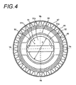
- Fig. 4 is a view from a direction (side into which the shaft member 70 is inserted) which is illustrated with an arrow IV in Fig. 3
- Fig. 5A is a sectional view along a line illustrated with Va-Va in Fig. 4
- Fig. 5B is a sectional view along a line illustrated with Vb-Vb in Fig. 4 .
- end surfaces (cut-out surfaces) in sectional views are illustrated by hatching.
- the bearing member 45 is provided with a tube-shaped body 46 which has a cylindrical shape.
- a contact wall 47 which has a shape of a ring that stands along the outer circumferential surface, and a gear 48 are formed.
- An outer diameter of the tube-shaped body 46 is generally the same as an inner diameter of the photoreceptor drum 35, and the bearing member 45 is fixed to the photoreceptor drum 35 by putting one end side of the tube-shaped body 46 into the photoreceptor drum 35 and making the one end side fit to the photoreceptor drum 35.
- the end surface of the photoreceptor drum 35 is inserted until the end surface reaches a part having a depth at which the end surface hits the contact wall 47.
- an adhesive may be used for more solid installation.
- a groove or an irregularity part may be provided in the tube-shaped body 46 of a part where the adhesive is disposed. Accordingly, the adhesive is held in the groove or a concave section, and further, solid adhesion is possible.
- the gear 48 is a gear which transmits the rotating force to a roller which is adjacent to the developing roller or the like, and in the embodiment, the gear 48 is a helical gear.
- a type of the gear is not particularly limited, and may be a spur gear. Alternatively, the gear is not necessarily provided.
- a holding section 50 is formed on an inner side which has a shape of a tube of the tube-shaped body 46.
- the holding section 50 is a part which holds the shaft member 70 swingably as will be described later, and is formed to have a spherical body receiving section 51 and an swing groove 52.
- the spherical body receiving section 51 is a part having a shape of a container in a cylinder having a bottom that is formed on the inner side of the tube-shaped body 46, and has a wall section 51a and a bottom section 51b.
- the wall section 51a is a cylindrical part which is concentric to the tube-shaped body 46.
- a diameter of the cylindrical inner side of the wall section 51a illustrated with F is generally the same as a diameter of a spherical body 90 of the shaft member 70 which will be described later.
- the bottom section 51b is a part which forms a bottom to cover one side end section of the cylindrical wall section 51a.
- the bottom section 51b has a shape which is curved in a hemispherical shape.
- a center C1 of the hemispherical shape of the bottom section 51b is formed to be on an axis of the bearing member 45, and a radius is generally the same as a radius of the spherical body 90 of the shaft member 70 which will be described later.
- a concave section 51c is formed on the inner side which is surrounded by the wall section 51a and the bottom section 51b, and a bottom (that is, the bottom section 51b) of the concave section 51c has a concave shape which is curved in a hemispherical shape.
- a side which is opposite to the bottom section 51b is opened.
- the concave section 51c is a space which receives the spherical body 90 of the shaft member 70 therein.
- the spherical body receiving section 51 is formed without providing an undercut section when viewed from a front surface in a direction of an axis as illustrated with an arrow Vc in Fig. 5B from the opened side of the concave section 51c.
- the phrase "without providing an undercut section” means that the bottom section 51b side of the concave section 51c when viewed from the arrow Vc is at a position which is closer to an axis side than the opened side of the concave section 51c or at the same position as that of the axis side, on an arbitrarily adjacent cross section which is orthogonal to the direction of the axis of the spherical body receiving section 51.
- a void is provided between an outer circumferential surface of the wall section 51a and an inner circumferential surface of the tube-shaped body 46.
- the swing groove 52 is a groove which is provided at a part of the wall section 51a of the spherical body receiving section 51, and extends in parallel to the direction of the axis of the bearing member 45. In the embodiment, two parallel swing grooves 52 are provided to oppose each other so that the axis of the bearing member 45 is located therebetween. As can be ascertained in Figs. 5A and 5B , the swing groove 52 is formed as a slit-shaped groove is provided from an end section which is on a side opposite to the opened section side of the concave section 51c in the tube-shaped body 46.
- the opened side end section of the concave section 51c in the swing groove 52 is curved so as to narrow a bottom clearance of the grooves.
- the curved part is formed along an arc around a point C2, the point C2 is generally at the same position as that of the point C1 which is on the axis of the tube-shaped body 46, and which is the hemispherical center of the bottom section 51b of the spherical body receiving section 51.
- the undercut section is not provided.
- the phrase "the undercut section is not provided” means that a side which is far from the arrow Vd is at a position which is closer to the axis side than a side near to the arrow Vd or at the same position as that of the axis side when viewed from the direction of the arrow Vd on an arbitrarily adjacent cross section which is orthogonal to the direction of the axis of the swing groove 52.
- it is not necessarily essential that the undercut section is not provided here. However, according to this configuration, as will be described later, it is possible to easily perform integral molding.
- a material which constitutes the bearing member 45 is not particularly limited, but resin made of polyacetal, polycarbonate, or PPS can be used.
- resin made of polyacetal, polycarbonate, or PPS in order to improve rigidity of the member, glass fibers, carbon fibers, or the like, may be mixed in the resin in accordance with a loading torque.
- a sliding characteristic in order to install the shaft member and smoothly perform a swing operation, a sliding characteristic may be improved by containing at least one of fluorine, polyethylene, and silicone rubber in the resin.
- the resin may be coated with fluorine, and may be coated with a lubricant.
- Fig. 6 is a perspective view of the shaft member 70
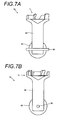
- Fig. 7A is a sectional view along line VIIa-VIIa of the shaft member 70 illustrated in Fig. 2B
- Fig. 7B is a sectional view along line VIIb-VIIb of the shaft member 70 illustrated in Fig. 2B
- the shaft member 70 is provided with a coupling member 71, a rotating shaft 85, a spherical body 90, and a rotating force transmission pin 95.
- the coupling member 71 is a part which functions as a rotating force receiving section that receives a rotation driving force from the apparatus body 10 (refer to Fig. 1 ).
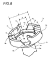
- Fig. 8 is an enlarged perspective view of the coupling member 71.
- the coupling member 71 is a member which has a shape of a circular dish, and an inner side thereof includes a bottom section 73 provided with a conical concave section 73a to be the deepest part through which the axis passes.
- a tube-shaped engagement wall 74 stands along an edge of a surface on one surface side (a side opposite to a side on which the rotating shaft 85 is provided).
- Two grooves 74a and 74b which oppose each other to locate the axis of the shaft member 70 therebetween are provided in the engagement wall 74.
- One pair of grooves 74a and the other pair of grooves 74b are shifted by 90 degrees around the axis.
- a convex section 75 is provided on one side wall of the groove, and a hollow 75a is provided in a circumferential direction on the bottom section 73 side thereof. According to this, as will be described later, a pin 12 of a driving shaft 11 of the apparatus body 10 is engaged with the hollow 75a and is prevented from falling out, and an appropriate rotating force is transmitted (refer to Fig. 22B ).
- inclined surfaces 74c are formed on side walls on the other sides of each of the grooves 74a and 74b, and an introduction of the pin 12 into the groove is easily performed.
- a width of the groove 74a illustrated with D in Fig. 8 is slightly greater than a diameter of the pin 12 (refer to Fig. 22B ) and is narrower than the driving shaft 11 so that the driving shaft 11 cannot pass therethrough.
- a diameter of an inner side of the engagement wall 74 illustrated with E in Fig. 8 is formed to be slightly greater than a diameter of the driving shaft 11, but generally, is the same level as the diameter of the driving shaft 11. In which manner the rotating force can be received from the driving shaft 11 will be described later.
- four (two pairs) grooves of the engagement wall are provided, but the number thereof is not particularly limited, and may be two (one pair), six (three pairs), or more than six.
- the rotating shaft 85 is a columnar shaft-like member which functions as a rotating force transmission section for transmitting the rotating force that the coupling member 71 receives. Therefore, the coupling member 71 is provided on one end of the rotating shaft 85.
- the spherical body 90 functions as a base end section, and in the embodiment, as can be ascertained from Figs. 6 to 7B , the spherical body 90 is a spherical member, and is provided in an end section on the side opposite to the side on which the coupling member 71 is disposed among the end sections of the rotating shaft 85.
- the axis of the rotating shaft 85 and the center of the spherical body 90 match each other as much as possible. Accordingly, it is possible to obtain a consistent rotation of the photoreceptor drum 35.
- the radius of the spherical body 90 is generally the same as, or slightly smaller than a hemispherical radius of the bottom section 51b of the holding section 50 of the bearing member 45. As apparently described above, the spherical body 90 does not regulate movement of the shaft member 70 in a falling-out direction (upward in Fig. 5A ) by the wall section 51a of the holding section 50 of the bearing member 45.
- a case where a normal sphere is used as the base end section is illustrated, but the present invention is not limited thereto.
- a case where at least a part thereof is spherical, or a case where egg-shaped curved surfaces are combined with each other may be employed.
- the rotating force transmission pin 95 is a columnar shaft-like member which passes through the center of the spherical body 90, and in which both ends are disposed to protrude from the spherical body 90 through the spherical body 90.
- the axis of the rotating force transmission pin 95 is provided to be orthogonal to the axis of the rotating shaft 85.
- a material of the shaft member 70 is not particularly limited, but a resin made of polyacetal, polycarbonate, or PPS can be used. However, in order to improve rigidity of the member, glass fibers, carbon fibers, or the like, may be mixed in the resin in accordance with a loading torque. In addition, rigidity may be further improved by inserting metal into the resin, or the entire member may be made of metal.
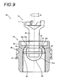
- Fig. 9 is a sectional view in the direction of the axis of the end section member 40 along the line illustrated with VIIa-VIIa in Fig. 2B
- Fig. 10 is a sectional view in the direction of the axis of the end section member 40 along the line illustrated with VIIb-VIIb in Fig. 2B
- Figs. 11A and 11B illustrate a posture in which the shaft member 70 is inclined.
- Fig. 11A illustrates swing motion of the shaft member 70 on the cross section illustrated in Fig. 9
- Fig. 11B illustrates swing motion of the shaft member 70 on the cross section illustrated in Fig. 10 .
- the spherical body 90 of the shaft member 70 is disposed inside the concave section 51c of the holding section 50.
- both end sections of the rotating force transmission pin 95 which protrude from the spherical body 90 are disposed inside the grooves of the two swing grooves 52.
- the shaft member 70 is held in the bearing member 45.
- the diameter of the cylindrical inner side of the wall section 51a that forms the concave section 51c is generally the same as the diameter of the spherical body 90
- the hemispherical radius of the bottom section 51b is generally the same as the radius of the spherical body 90. Accordingly, smooth swinging without rattling is possible.
- the width of a groove of the swing groove 52 is formed to be slightly wider than a diameter of the rotating force transmission pin 95, and a clearance between bottom parts of the two opposing swing grooves 52 is configured to be greater than the length of the rotating force transmission pin 95.
- the shaft member 70 can rotate (swing) in a direction in which the axis itself of the rotating force transmission pin 95 swings. This is possible as each of both end sections of the rotating force transmission pin 95 move in a longitudinal direction of the groove in the swing groove 52.
- the shaft member 70 can rotate (swing) around the axis of the rotating force transmission pin 95.
- rotation (swinging) in a direction which is orthogonal to a direction illustrated in Fig. 11A around the axis of the rotating force transmission pin 95 is possible.
- the shaft member 70 when receiving the driving shaft from the apparatus body 10, as illustrated with IX in Fig. 9 and with X in Fig. 10 , the shaft member 70 receives the rotating force around the axis thereof.
- the coupling member 71 receives the rotation driving force from the apparatus body 10, and following this, the spherical body 90 and the rotating force transmission pin 95 rotate interlocking with each other.
- both end sections of the rotating force transmission pin 95 are hooked to a groove side surface (groove side wall) of the swing groove 52, and transfer the rotating force to the bearing member 45, and then, to the photoreceptor drum 35.
- Fig. 12 is a view illustrating a posture of the shaft member 70 and the bearing member 45 in a situation in which the shaft member 70 is pulled in the direction of the axis.
- a locking section 52a which is curved in a shape of an arc is provided in the end section of the swing groove 52 as described above, and a bottom clearance of the opposing swing grooves 52 is narrow.
- the length of the rotating force transmission pin 95 is set to be longer than a distance of the clearance between the bottom parts of the swing groove 52 in the locking section 52a, even when the shaft member 70 is pulled in the direction of the axis, as illustrated in Fig.
- the shaft member 70 is not removed from the bearing member 45 since the rotating force transmission pin 95 is hooked to the locking section 52a of the swing groove 52.
- the movement of the shaft member 70 in the direction of the axis is regulated by the rotating force transmission pin 95 and the locking section 52a of the swing groove 52.
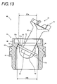
- Fig. 13 illustrates a posture in which the shaft member 70 is inclined at the most in cross sections illustrated in Fig. 9 .
- the posture in which the rotating force transmission pin 95 makes the shaft member 70 inclined at the mostaround the center of the longitudinal direction of the rotating force transmission pin 95. Therefore, one end of the rotating force transmission pin 95 reaches the locking section 52a of the swing groove 52, and the other end is inclined to be isolated from the locking section 52a.
- a distance illustrated with XIIIa in Fig. 13 represents a distance of the clearance between the bottom parts of the swing groove 52 in the locking section 52a.
- a distance illustrated with XIIIb in Fig. 13 represents a distance of the clearance between the end sections of the rotating force transmission pin 95 in a radial direction of the tube-shaped body 46 in a posture of the shaft member 70 illustrated in Fig. 13 .
- the distance illustrated with XIIIb is formed to be longer than the distance illustrated with XIIIa.
- the rotating force transmission pin 95 is reliably hooked to the locking section 52a of the swing groove 52 even when the shaft member 70 is inclined at the most, there is not a case where the shaft member 70 is removed from the bearing member 45 at least automatically or by a slight external force. Therefore, it is possible to hold the shaft member 70 in the bearing member 45, and the shaft member 70 can function as the end section member 40 without being removed from the bearing member 45 in an unintended situation.
- taking the shaft member 70 off of the bearing member 45 can be performed by applying a slightly strong force from the posture illustrated in Fig. 13 , bending the locking section 52a, and separating one end side of the rotating force transmission pin 95 from the holding section 50. Installing the shaft member 70 to the bearing member 45 may be performed in reverse thereto.
- end section member 40 By the end section member 40, it is possible to give an appropriate rotating force to the photoreceptor drum 35 when mounting the process cartridge 20, and to easily attach and detach the process cartridge 20.
- the bearing member 45 and the shaft member 70 which constitute the end section member 40 may be configured as a plurality of components are combined with each other, or may be integrally molded as will be described later.
- the components may be formed of the same material, or may be formed of different materials.
- the components can be bonded by employing known means, such as bonding by an adhesive, an ultrasound wave, heat sealing, a screw, and a bolt.
- the bearing member 45 is molded by injection molding as the undercut section is not provided in the concave section and the swing groove as described in the example above. In other words, molding is performed by combining a plurality of molds with each other, injecting a certain flowable material and filling a void section of the combined mold with the material, solidifying the injected material, and then, by disengaging the mold. Therefore, in molding the bearing member 45, a mold for forming shapes of an outer circumferential side and an inner side of the tube-shaped body 46 is necessary. Here, molding of the inner side will be described.
- the shape (for example, the gear 48) of the outer circumferential side of the tube-shaped body 46 can be molded by a known method.
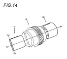
- Fig. 14 is a perspective view of a first mold 100 and a second mold 110 which mold the shape of the inner side of the bearing member 45.
- the molded bearing member 45 is also illustrated together with a dashed line.
- Figs. 15A to 15C are sectional views in the direction of the axis including a line illustrated with XV-XV in Fig. 14 .
- Figs. 16A to 16C are sectional views in the direction of the axis including a line illustrated with XVI-XVI in Fig. 14 .
- the shape of the inner side of the bearing member 45 is molded by the two molds, including the first mold 100 and the second mold 110.
- the first mold 100 is provided with a bottomed cylindrical section 101 and a concave section forming section 102.
- a cylindrical part of the bottomed cylindrical section 101 is in a shape which forms a void between an inner surface of a cylindrical body of the bearing member 45 and an outer circumferential section of the wall section 51a.
- the concave section forming section 102 is provided to protrude from a bottom of the bottomed cylindrical section 101, and is disposed on an inner side of the bottomed cylindrical section 101.
- the concave section forming section 102 has a shape which can form the spherical body receiving section 51, and has a shape of a dome to correspond to the concave section 51c.
- a void is formed between the bottomed cylindrical section 101 and the concave section forming section 102, and the void has a shape which molds the wall section 51a of the bearing member 45.
- a groove 100a into which the second mold 110 is inserted is formed in the first mold 100.
- the groove 100a has a depth to a position at which the swing groove 52 is formed.
- the second mold 110 is a mold for forming the swing groove 52, and is a plate-shaped member. Therefore, the thickness of the second mold 110 is generally the same as the width of the groove of the swing groove 52, and as can be ascertained from Fig. 16C , a curved section 110a for forming the locking section 52a is formed to narrow the width of the plate of the second mold 110 on one end side of the second mold 110.
- Figs. 17A and 17B are views in which the first mold 100 and the second mold 110 are combined with each other.
- Fig. 17A is a sectional view from the same viewpoint as that in Figs. 15A to 15C .
- Fig. 17B is a sectional view from the same viewpoint as that in Figs. 16A to 16C .
- the first mold 100 and the second mold 110 are combined with each other as the second mold 110 is inserted into the groove 100a of the first mold 100.
- the curved section 110a of the second mold 110 is combined to be a deep part (a side opposite to an opening section of the groove 100a) of the groove 100a.
- the bearing member 45 described above has a shape which can smoothly and efficiently perform manufacturing by integral molding, and productivity can be improved.
- Figs. 18A and 18B are views illustrating a bearing member 145 and an end section member 140 in which the shaft member 70 is installed to the bearing member 145 according to a second embodiment.
- Fig. 18A is a view which corresponds to Fig. 5A .
- Fig. 18B is a view which corresponds to Fig. 13 .
- a protruded section 152a having a shape of a wedge is provided to further narrow a clearance between two swing grooves 152 in the end section on the opened section side of the concave section 51c of the swing groove 152.
- Other parts of the structure are similar to those of the bearing member 45 and the end section member 40.
- Figs. 19A and 19B are views illustrating a bearing member 245, and an end section member 240 in which the shaft member 70 is installed to the bearing member 245 according to a third embodiment.
- Fig. 19A is a view which corresponds to Fig. 5A .
- Fig. 19B is a view which corresponds to Fig. 13 in which the shaft member 70 is installed to the bearing member in the Fig. 5A .
- the above-described protruded section 152a is provided in the end section on the opened section side of the concave section 51c of an swing groove 252. Furthermore, in the bearing member 245, in the swing groove 252, a step 252a is provided so that the clearance between the two swing grooves 252 widens as being isolated from an axis of the bearing member 245, from the end section on the side opposite to the protruded section 152a of the curved locking section 52a. Other parts of the structure are similar to those of the bearing member 45 and the end section member 40.
- Figs. 20A to 20F illustrate explanation views. Figs. 20A to 20F are illustrated following an order of installation of the shaft member 70 to the bearing member 245. The order will be described hereinafter.
- Figs. 20A to 20F many reference numerals are omitted in order to make the drawings easy to understand, but it is possible to refer to Figs. 19A and 19B regarding the omitted reference numerals.
- the rotating force transmission pin 95 of the shaft member 70 protrudes as being largely put aside so that only one end section thereof protrudes from the spherical body 90.
- the shaft member 70 is inclined so that the protruded end section of the rotating force transmission pin 95 reaches the step 252a of the swing groove, and the spherical body 90 is inserted into the concave section 51c of the bearing member 45.
- the shaft member 70 is gradually raised along the direction of the axis of the bearing member 245. Accordingly, the end section of the rotating force transmission pin 95 which protrudes from the spherical body 90 is pressed from a bottom section of the swing groove 252 to an extent to exceed the step 252a, and the rotating force transmission pin 95 moves to the opposite side in the direction of the axis thereof.
- the rotating force transmission pin 95 provided in the shaft member 70 of the end section member 240 is configured to become a posture in which both ends of the rotating force transmission pin 95 protrude from the spherical body 90, and a posture in which only one end of the rotating force transmission pin 95 protrudes.
- the curved part 52a of the swing groove 252 of the bearing member 245 by the curved part 52a of the swing groove 252 of the bearing member 245, the movement of the rotating force transmission pin 95 in the swing groove 252 is regulated.
- the spherical body 90 can rotate in the concave section of the bearing member 245, the movement of the rotating force transmission pin 95 in the direction of the axis of the bearing member 245 is regulated by the curved part 52a of the swing groove 252, and the shaft member 70 is installed to the bearing member 245 to be turnable in a posture in which the movement is regulated.
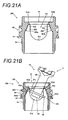
- Figs. 21A and 21B are views illustrating a bearing member 345 and an end section member 340 in which the shaft member 70 is installed to the bearing member 345 according to a fourth embodiment.
- Fig. 21A is a view which corresponds to Fig. 5A .
- Fig. 21B is a view which corresponds to Fig. 13 in which the shaft member 70 is installed to the shaft member in the Fig. 5A .
- the above-described protruded section 152a is provided in the end section on the opened section side of the concave section 51c of an swing groove 352. Furthermore, in the bearing member 345, in the swing groove 352, an inclined section 352a is provided so that the clearance between the two swing grooves 352 widens as being isolated from the axis, from the end section on the side opposite to the protruded section 152a of the curved locking section 52a. Other parts of the structure are similar to those of the bearing member 45 and the end section member 40.
- the end section member 340 As can be ascertained from Fig. 21B , it is possible to reliably prevent the rotating force transmission pin 95 from being hooked to the protruded section 152a in the posture in which the shaft member 70 is inclined at the most, and further, to reliably prevent the shaft member 70 from being removed in an unintended situation.
- the inclined section 352a acts similarly to the step 252a of the bearing member 245, and the shaft member 70 can be smoothly installed.
- the charging roller, the developing roller, the developing blade, the transfer roller, and the cleaning blade which are other constituent elements provided inside the housing 21 of the process cartridge 20
- known members can be employed, and examples thereof are as follows.
- the charging roller charges the photoreceptor drum 35 by applying a voltage from the apparatus body 10. Charging is performed as the charging roller rotates following the photoreceptor drum 35, and comes into contact with the outer circumferential surface of the photoreceptor drum 35.
- the developing roller is a roller which supplies a developer to the photoreceptor drum 35.
- an electrostatic latent image which is formed in the photoreceptor drum 35 is developed.
- the developing roller has a fixed magnet embedded therein.
- the developing blade is a blade which adjusts an amount of the developer which adheres to the outer circumferential surface of the developing roller, and gives a frictional electrification charge to the developer itself.
- the transfer roller is a roller for transferring the image which is formed in the photoreceptor drum 35 to the recording medium, such as a paper sheet.
- the cleaning blade is a blade which comes into contact with the outer circumferential surface of the photoreceptor drum 35 and eliminates the developer that remains after transferring by the tip end thereof.
- Each of the rollers is stored inside the housing 21 to be rotatable. In other words, each roller realizes functions thereof by rotating as necessary inside the housing 21.
- the coupling member 71 is disposed to be exposed from the housing 21. Accordingly, as will be described later, it is possible to obtain the rotation driving force from the apparatus body 10, and attaching and detaching the apparatus body 10 and the process cartridge 20 becomes easy.
- each roller and blade that is provided in the process cartridge 20 is described, but the members provided here are not limited thereto, and it is preferable that the members, parts, and developers which are generally provided in other process cartridges are provided.
- the apparatus body 10 of the embodiment is a laser printer.
- the laser printer an operation is performed in a posture in which the process cartridge 20 is mounted, and when an image is formed, the photoreceptor drum 35 is rotated, and charging is performed by the charging roller.
- the photoreceptor drum 35 is irradiated with laser light which corresponds to image information by using various optical members provided here, and an electrostatic latent image based on the image information is obtained.
- the latent image is developed by the developing roller.
- the recording medium such as the paper sheet
- the recording medium is set in the apparatus body 10, and transferred to a transfer position by a feeding roller or a transporting roller, which is provided in the apparatus body 10.
- the transfer roller is disposed at the transfer position, a voltage is applied to the transfer roller as the recording medium passes, and the image is transferred to the recording medium from the photoreceptor drum 35. After this, the image is fixed to the recording medium as heat and pressure are applied to the recording medium.
- the recording medium on which the image is formed is discharged from the apparatus body 10 by a discharging roller or the like.
- the apparatus body 10 gives the rotation driving force to the photoreceptor drum unit 30.
- the rotation driving force is given to the photoreceptor drum unit 30 from the apparatus body 10 in the posture in which the process cartridge 20 is mounted, will be described.
- Fig. 22A illustrates a shape of a tip end section of the driving shaft 11.
- the tip end of the driving shaft 11 is a columnar shaft member which is a hemispherical surface, and the columnar pin 12 which serves as the rotating force giving section that protrudes in a direction which is orthogonal to an axis of rotation illustrated with one-dot chain line is provided.
- a gear row is formed so as to make it possible to rotate the driving shaft 11 around the axis, and according to this, the gear row is connected to a motor which is a driving source.
- the driving shaft 11 is disposed to protrude on a track of the movement of attaching and detaching generally at a right angle. In addition to this, the driving shaft 11 only rotates without moving in the direction of the axis. Therefore, in attaching and detaching the process cartridge 20, it is necessary to mount and disengage the shaft member 70 to and from the driving shaft 11. In addition, according to the end section member 40, mounting and disengaging the shaft member 70 to and from the driving shaft 11 becomes easy. A specific aspect of attaching and detaching will be described later in detail.
- Fig. 22B illustrates a situation in which the coupling member 71 of the end section member 40 is engaged with the driving shaft 11.
- the axis of the driving shaft 11 and the axis of the coupling member 71 are disposed to be abutted against each other so that the axes match each other.
- the pin 12 of the driving shaft 11 is disposed on inner sides of the groove 74a and the groove 74b that oppose each other in the coupling member 71 (in Fig. 22B , a case where the pin 12 is disposed on the inner side of the groove 74a). Accordingly, the coupling member 71 rotates following the rotation of the driving shaft 11, and the photoreceptor drum unit 30 rotates.
- a posture in which the rotating force is transmitted is a posture in which the axis of the driving shaft 11 and the coupling member 71 are disposed coaxially, and the pin 12 is on the inner sides of the groove 74a and the groove 74b.
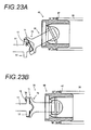
- Figs. 23A and 23B are explanation views.
- Fig. 23A is a view illustrating one situation in which the end section member 40 is mounted on the driving shaft 11.
- Fig. 23B is a view illustrating another situation in which the end section member 40 is mounted on the driving shaft 11.
- An order of the operations is illustrated in Figs. 23A and 23B , and right and left on a paper surface is an orientation which becomes the direction of the axis.
- the situation is a situation in which the process cartridge 20 is moved to a lower part on the paper surface and mounted.
- this posture is a posture in which the shaft member 70 is inclined at the most.
- the tip end of the driving shaft 11 comes into contact with the inner side of the bottom section 73 of the coupling member 71 or the engagement wall 74 being hooked thereto.
- the driving shaft 11 which comes into contact with the coupling member 71 being hooked thereto rotates to exceed the inclined shaft member 70.
- the pin 12 is inserted to the inside of the groove 74a.
- a bearing member, an end section member, and a photoreceptor drum unit which can perform production by suppressing issues, such as damage, with high precision, are provided.
Landscapes
- Engineering & Computer Science (AREA)
- Physics & Mathematics (AREA)
- General Physics & Mathematics (AREA)
- General Engineering & Computer Science (AREA)
- Mechanical Engineering (AREA)
- Manufacturing & Machinery (AREA)
- Electrophotography Configuration And Component (AREA)
- Discharging, Photosensitive Material Shape In Electrophotography (AREA)
Abstract
Description
- The present invention relates to a photoreceptor drum unit which is provided in an image forming apparatus, such as a laser printer or a copying machine, a bearing member which is disposed in the photoreceptor drum unit, an end section member, and a method for manufacturing the bearing member.
- In an image forming apparatus which is represented by a laser printer or a copying machine, a process cartridge which is attachable to and detachable from a body (hereinafter, refer to as an "apparatus body") of the image forming apparatus is provided.
- The process cartridge is a member which forms contents to be expressed by letters or figures and transfers the contents to a recording medium, such as a paper sheet, and here, includes a photoreceptor drum in which the transferred contents are formed. Furthermore, in the process cartridge, in addition to the photoreceptor drum, various means for forming the contents to be transferred by acting on the photoreceptor drum are disposed. Examples of these means include means for developing on a surface of the photoreceptor drum, means for charging the photoreceptor drum, and means for cleaning the photoreceptor drum.
- In case of the process cartridge, the same process cartridge is attached to and detached from the apparatus body for maintenance, or a new process cartridge is mounted on the apparatus body instead of disengaging an old process cartridge from the apparatus body for replacing the process cartridge with a new process cartridge. Attaching and detaching the process cartridge in this manner is performed by users of the image forming apparatus themselves, and it is desirable to easily perform attaching and detaching as much as possible from such a point of view.
- However, a driving shaft of the apparatus body is engaged with the photoreceptor drum which is included in the process cartridge directly or via another member, and according to this, the photoreceptor drum receives a rotating force from the driving shaft and rotates. Therefore, in order to attach and detach the process cartridge to and from the apparatus body, it is necessary to release (disengage) the engagement between the driving shaft of the apparatus body and the photoreceptor drum every time attaching and detaching the process cartridge occurs, and to mount the process cartridge again.
- Here, if it is possible to move the photoreceptor drum (process cartridge) in a direction of an axis of the driving shaft of the apparatus body, and to attach and detach the photoreceptor drum, the above-described structure for attaching and detaching can be relatively easily configured. However, from the viewpoint of reducing the image forming apparatus in size or ensuring an attachment and detachment space of the process cartridge, it is preferable to disengage the process cartridge from the apparatus body to be pulled out in a direction which is different from the direction of the axis of the driving shaft, and to mount the process cartridge to the apparatus body to be pushed in this direction.
- In Patent Literature 1, a structure for attaching and detaching a process cartridge in a direction which is different from a direction of an axis of a driving shaft of an apparatus body is disclosed. Specifically, a coupling member which is disclosed in Patent Literature 1 is swingably installed to a drum flange by providing a spherical section. Therefore, a part which is provided in the coupling member and engages with the driving shaft of the apparatus body can swing around the spherical section, an angle with respect to the axis of the photoreceptor drum can be changed, and disengagement between the driving shaft of the apparatus body and the photoreceptor drum becomes easier.
- In addition, in Non-Patent Literature 1, a structure, in which a groove for introducing a rotating force transmission pin provided in a shaft member to a bearing member is provided in a rotating direction of an inner circumference of the bearing member, and installation of the rotating force transmission pin to the bearing member is easily performed due to the groove, is disclosed. In addition, here, a technology for integrally molding the bearing member is also described.
- Patent Literature 1:
JP-A-2010-26473 - Non-Patent Literature 1: Japan Institute of Invention and Innovation Journal of Technical disclosure, Japan Institute for Promoting Invention and Innovation No.
2010-502200 - However, in the structure of the coupling member described in Patent Literature 1 and the drum flange (bearing member) for holding the coupling member, in order to make a structure which holds the spherical section to the drum flange while allowing the coupling member to swing, it is necessary to forcibly insert the spherical section when installing the spherical section to the drum flange (bearing member). In assembling the spherical section forcibly, there is a concern that assembly precision deteriorates or components are damaged during the assembly.
- In addition, In Patent Literature 1, a method for assembling other components of the coupling member in order after positioning a part of the components by decomposing the coupling member to the drum flange (bearing member), is also described. According to this, there are no issues, such as the forcible insertion, but there are still the issues of man-hours increasing, and productivity deteriorating. In other words, from the viewpoint of production, there is also a problem in that production cost increases due to an increase in man-hours or an increase in the number of components, or the number of quality control items increase, for example, assembly precision deteriorates. From the same viewpoint, it is desirable to reduce the number of components as much as possible, not being limited to complete integration.
- In addition, it is also difficult to install the drum flange (bearing member) on which the coupling member is swingably installed in this manner to an end section of the photoreceptor drum with high precision. Furthermore, according to the structure in which the coupling member or the drum flange are formed of a plurality of members in this manner, and manufacturing is performed while the components are assembled consecutively, there is a concern that a problem in strength of bonding locations between the members is generated.
- Meanwhile, it is possible to solve the problems according to Non-Patent Literature 1, but since the groove for inserting the rotating force transmission pin of the shaft member is linked to a side wall section of a groove for swinging, there is a concern that the shaft member is carelessly removed.
- In addition, in Non-Patent Literature 1, a method for integrally molding is disclosed, but it is difficult to realize smooth installation of the shaft member with only the method disclosed in Non-Patent Literature 1, smooth swinging of the shaft member, and smooth attachment and detachment of the shaft member to and from the apparatus body.
- Here, in consideration of the above-described problems, an object of the present invention is to provide a bearing member, an end section member, and a photoreceptor drum unit, which can easily perform production by suppressing issues, such as damage, with high precision, while it is possible to transfer the equivalent rotating force to that of the related art, and to attach and detach the shaft member to and from the apparatus body. In addition, there is provided a manufacturing method of such an end section member.
- Hereinafter, the present invention will be described. Here, a part of reference numerals in the drawings is illustrated as an example by being written in parentheses in order to make it easy to understand, but the present invention is not limited thereto.
- An aspect of the present invention provides a bearing member (45) to be disposed in an end section of a photoreceptor drum (35), wherein a shaft member (70) which includes a spherical body (90) of which at least one part is spherical and a rotating force transmission pin (95) provided to protrude from the spherical body is swingably installed in the bearing member, the bearing member including: a concave section (51c) in which one section is opened and a bottom section (51b) on a side opposite to the one section has a curved surface along the spherical body, the concave section receiving the spherical body therein; and at least two swing grooves (52) being grooves which are provided on a side surface of the concave section and into which end sections of the rotating force transmission pin are inserted, wherein the swing groove at least includes a parallel part which is parallel to an axis of the bearing member and a curved part (52a) curved toward the axis, wherein an undercut section is not provided in the concave section when the concave section is viewed from an opened side of the concave section in a direction of the axis of the bearing member, and wherein a clearance (XIIIa) between the two swing grooves in a direction which is orthogonal to the direction of the axis on the opened side of the concave section is formed to be shorter than a distance (XIIIb) between both ends of the rotating force transmission pin in the direction which is orthogonal to the axis of the bearing member even when the shaft member is mounted on the bearing member in a posture inclined at the most.
- As an aspect of the bearing member (145) according to the present invention, the bearing member further includes a protruded section (152a) provided at the curved part (52a) of the swing groove (152).
- As an aspect of the bearing member (45) according to the present invention, the curved part (52a) of the swing groove (52) is formed in an arc shape, and a center of the arc-shape matches a center of the curved surface of the bottom section (52b) of the concave section (51c) of the bearing member (45).
- As an aspect of the bearing member (245, 345) according to the present invention, the swing groove (252, 352) is provided with a step (252a) or an inclination (352a) in a direction of separating from the axis of the bearing member (245, 345) between the curved part (52a) and the parallel part.
- As an aspect of the bearing member (45) according to the present invention, an undercut section is not provided in the swing groove (52) when the bearing member is viewed from the side opposite to the opened side of the concave section (51c).
- As an aspect of the bearing member (45) according to the present invention, all elements of the bearing member are integrally formed.
- An end section member (40) according to an aspect of the present invention includes: the bearing member (45) according to the aspect of the present invention; and a shaft member (70) which is swingably installed to the bearing member, wherein the shaft member includes: a rotating force receiving section to be linked to a rotating driving shaft; a spherical body (90) which is interlocked with the rotating force receiving section, and in which at least a part disposed in the concave section of the bearing member is spherical; and a rotating force transmission pin (95) which protrudes from the spherical body and in which the protruded part is movable in the swing groove (52) of the bearing member.
- As an aspect of the end section member (40) according to the present invention, the shaft member is prevented from being removed from the bearing member as the rotating force transmission pin (95) of the shaft member (70) is hooked to the curved part (52a) of the swing groove (52) of the bearing member (45).
- As an aspect of the end section member (240) according to the present invention, the rotating force transmission pin (95) of the shaft member (70) is allowed to be in a posture in which both ends of the rotating force transmission pin protrude from the spherical body (90), and a posture in which only one end of the rotating force transmission pin protrudes, wherein the spherical body is rotatable in the concave section of the bearing member by the curved part (52a) of the swing groove (252) of the bearing member (245) within a range where the movement of the rotating force transmission pin in the swing groove is regulated, and wherein the movement of the rotating force transmission pin in the direction of the axis of the bearing member is regulated by the curved part of the swing groove, and the shaft member is installed to the bearing member to be turnable in a posture in which the movement is regulated.
- A photoreceptor drum unit according to an aspect of the present invention includes: a photoreceptor drum; and the end section member according to the aspect of the present invention which is installed at least to one of end sections in a direction of an axis of the photoreceptor drum.
- A method for manufacturing a bearing member (45) includes a step of forming by injection molding, wherein the step includes combining a first mold (100) which forms the concave section (51c) and a second mold (110) which forms the swing grooves (52) by putting the second mold into a groove (100a) provided in the first mold, performing the injection molding and pulling apart the first mold and the second mold in opposite directions to each other.
- According to the end section member and the photoreceptor drum unit of the present invention, it is possible to easily perform production by suppressing issues, such as damage, with high precision, while it is possible to transfer the equivalent rotating force to that of the related art, and to attach and detach the shaft member to and from the apparatus body. In addition, it is possible to prevent the shaft member from being unintentionally removed from the bearing member.
- Meanwhile, according to a method for manufacturing the bearing member, in a case of an aspect in which an undercut section is not provided, it is possible to more efficiently manufacture the bearing member.
-
-
Fig. 1 is a schematic view of an image forming apparatus body and a process cartridge. -
Fig. 2A is a perspective view of an external appearance of a photoreceptor drum unit according to one embodiment. -
Fig. 2B is a perspective view of an external appearance of an end section member. -
Fig. 3 is a perspective view of an external appearance of a bearing member. -
Fig. 4 is a plan view when viewed from a direction illustrated with an arrow IV ofFig. 3 . -
Fig. 5A is a sectional view along line Va-Va ofFig. 4 . -
Fig. 5B is a sectional view along line Vb-Vb ofFig. 4 . -
Fig. 6 is a perspective view of the bearing member. -
Fig. 7A is a sectional view along line VIIa-VIIa of a shaft member illustrated inFig. 2B . -
Fig. 7B is a sectional view along line VIIb-VIIb of the shaft member illustrated inFig. 2B -
Fig. 8 is an enlarged view of a coupling member. -
Fig. 9 is a sectional view of the end section member in a direction of an axis along a line illustrated with VIIa-VIIa inFig. 2B . -
Fig. 10 is a sectional view of the end section member in the direction of the axis along a line illustrated with VIIb-VIIb inFig. 2B . -
Fig. 11A is a view illustrating a situation in which the shaft member swings on the cross section illustrated inFig. 9 . -
Fig. 11B is a view illustrating a situation in which the shaft member swings on the cross section illustrated inFig. 10 . -
Fig. 12 is a view illustrating a posture in which the shaft member moves in a direction of an axis. -
Fig. 13 is a view illustrating a posture when the shaft member is inclined at the most. -
Fig. 14 is a perspectiveview illustrating molds member 45. -
Figs. 15A to 15C are sectional views in the direction of the axis including a line illustrated with XV inFig. 14 . -
Figs. 16A to 16C are sectional views in the direction of the axis including a line illustrated with XVI inFig. 14 . -
Fig. 17A is a view illustrating a posture in which thefirst mold 100 and thesecond mold 110 are combined with each other, from the viewpoint ofFigs. 15A to 15C . -
Fig. 17B is a view illustrating a posture in which thefirst mold 100 and thesecond mold 110 are combined with each other, from the viewpoint ofFigs. 16A to 16C . -
Fig. 18A is a sectional view of a bearingmember 145 according to another embodiment. -
Fig. 18B is a sectional view of anend section member 140. -
Fig. 19A is a view illustrating a bearingmember 245. -
Fig. 19B is a view illustrating anend section member 240. -
Figs. 20A to 20F are views illustrating an assembly of theend section member 240. -
Fig. 21A is a view illustrating a bearingmember 345. -
Fig. 21B is a view illustrating anend section member 340. -
Fig. 22A is a perspective view illustrating a driving shaft of an image forming apparatus body and a pin. -
Fig. 22B is a view illustrating a posture in which the pin is linked to the coupling member. -
Figs. 23A and 23B are views illustrating an example of a situation in which a process cartridge is mounted on the apparatus body. - The above-described effects and advantages of the present invention are apparent from the aspects for realizing the invention which will be described in the following. Hereinafter, the present invention will be described based on embodiments illustrated in the drawings. However, the present invention is not limited to the embodiments.
-
Fig. 1 is a schematic perspective view illustrating aprocess cartridge 20 which is provided with an end section member 40 (refer toFigs. 2A and 2B ), and an image forming apparatus body 10 (hereinafter, there is a case of being referred to as a "apparatus body 10") which uses theprocess cartridge 20 by mounting theprocess cartridge 20 on theapparatus body 10 according to a first embodiment. As illustrated inFig. 1 , theprocess cartridge 20 can be mounted on theapparatus body 10 by being moved in a direction illustrated with A inFig. 1 , and can be disengaged. The direction is different from a direction of an axis of a driving shaft of theapparatus body 10. In addition, an image forming apparatus is made of theapparatus body 10 and theprocess cartridge 20, and hereinafter, will be described in detail. - The
process cartridge 20 includes ahousing 21 shaping an outline thereof, and includes various components inside thereof. Specifically, in the embodiment, a photoreceptor drum unit 30 (refer toFig. 2A ), a charging roller, a developing roller, a developing blade, a transfer roller, and a cleaning blade, are provided. - The
photoreceptor drum unit 30 is a member which forms letters or figures to be transferred to a recording medium, such as a paper sheet.Fig. 2A illustrates a perspective view of an external appearance of thephotoreceptor drum unit 30. As can be ascertained fromFig. 2A , thephotoreceptor drum unit 30 is provided with aphotoreceptor drum 35, alid member 36, and anend section member 40.Fig. 2B is a perspective view focusing theend section member 40. Hereinafter, with reference toFigs. 2A and 2B and other drawings, thephotoreceptor drum unit 30 will be described. - The
photoreceptor drum 35 is a member which is covered with a photoreceptor layer on an outer circumferential surface of a drum cylinder which has a cylindrical shape. In other words, the drum cylinder is covered with the photoreceptor layer on a conductive cylinder, such as aluminum, theend section member 40 is installed to one end of the drum cylinder as will be described later, and thelid member 36 is disposed at the other end. In the embodiment, the drum cylinder has a cylindrical shape, but may have a solidly columnar shape. However, at least thelid member 36 and theend section member 40 are formed to be appropriately installed in the end sections of the drum cylinder. - The
lid member 36 is a member which is formed of a resin, and a fitting section which is fitted to the inside of the cylinder of thephotoreceptor drum 35, and a bearing section which is disposed to cover one end surface of thephotoreceptor drum 35 are formed coaxially. The bearing section has a shape of a disk which covers the end surface of thephotoreceptor drum 35, and is provided with a part that receives a shaft of theapparatus body 10. In addition, an earth plate which is made of a conductive material is disposed in thelid member 36, and according to this, thephotoreceptor drum 35 and theapparatus body 10 are electrically connected to each other. - In addition, in the embodiment, an example of the lid member is described, but the lid member is not limited thereto, and it is possible to employ a lid member which is generally obtained according to another embodiment. For example, a gear for transmitting a rotating force to the lid member may be disposed.
- In addition, conductive materials as described below may be provided on the
end section member 40 side which will be described later. - The
end section member 40 is a member which is installed in the end section on a side opposite to thelid member 36 among the end sections of thephotoreceptor drum 35, and is provided with a bearingmember 45 and ashaft member 70. - The bearing
member 45 is a member which is fixed to the end section of thephotoreceptor drum 35.Fig. 3 is a perspective view of the bearingmember 45. In addition,Fig. 4 is a view from a direction (side into which theshaft member 70 is inserted) which is illustrated with an arrow IV inFig. 3 , and respectively,Fig. 5A is a sectional view along a line illustrated with Va-Va inFig. 4 andFig. 5B is a sectional view along a line illustrated with Vb-Vb inFig. 4 . In addition, inFigs. 5A and 5B , end surfaces (cut-out surfaces) in sectional views are illustrated by hatching. - In the embodiment, as can be ascertained from
Figs. 2 to 5B , the bearingmember 45 is provided with a tube-shapedbody 46 which has a cylindrical shape. In addition, on an outer circumferential surface of the tube-shapedbody 46, acontact wall 47 which has a shape of a ring that stands along the outer circumferential surface, and agear 48 are formed. An outer diameter of the tube-shapedbody 46 is generally the same as an inner diameter of thephotoreceptor drum 35, and the bearingmember 45 is fixed to thephotoreceptor drum 35 by putting one end side of the tube-shapedbody 46 into thephotoreceptor drum 35 and making the one end side fit to thephotoreceptor drum 35. At this time, the end surface of thephotoreceptor drum 35 is inserted until the end surface reaches a part having a depth at which the end surface hits thecontact wall 47. At this time, an adhesive may be used for more solid installation. In addition, a groove or an irregularity part may be provided in the tube-shapedbody 46 of a part where the adhesive is disposed. Accordingly, the adhesive is held in the groove or a concave section, and further, solid adhesion is possible. - The
gear 48 is a gear which transmits the rotating force to a roller which is adjacent to the developing roller or the like, and in the embodiment, thegear 48 is a helical gear. A type of the gear is not particularly limited, and may be a spur gear. Alternatively, the gear is not necessarily provided. - A holding
section 50 is formed on an inner side which has a shape of a tube of the tube-shapedbody 46. The holdingsection 50 is a part which holds theshaft member 70 swingably as will be described later, and is formed to have a sphericalbody receiving section 51 and answing groove 52. - The spherical
body receiving section 51 is a part having a shape of a container in a cylinder having a bottom that is formed on the inner side of the tube-shapedbody 46, and has awall section 51a and abottom section 51b. - As can be ascertained from
Figs. 4 and5B , thewall section 51a is a cylindrical part which is concentric to the tube-shapedbody 46. InFigs. 4 and5B , a diameter of the cylindrical inner side of thewall section 51a illustrated with F is generally the same as a diameter of aspherical body 90 of theshaft member 70 which will be described later. - Meanwhile, the
bottom section 51b is a part which forms a bottom to cover one side end section of thecylindrical wall section 51a. In addition, thebottom section 51b has a shape which is curved in a hemispherical shape. As illustrated inFig. 5B , a center C1 of the hemispherical shape of thebottom section 51b is formed to be on an axis of the bearingmember 45, and a radius is generally the same as a radius of thespherical body 90 of theshaft member 70 which will be described later. - In addition, a
concave section 51c is formed on the inner side which is surrounded by thewall section 51a and thebottom section 51b, and a bottom (that is, thebottom section 51b) of theconcave section 51c has a concave shape which is curved in a hemispherical shape. In theconcave section 51c, a side which is opposite to thebottom section 51b is opened. Theconcave section 51c is a space which receives thespherical body 90 of theshaft member 70 therein. - Here, the spherical
body receiving section 51 is formed without providing an undercut section when viewed from a front surface in a direction of an axis as illustrated with an arrow Vc inFig. 5B from the opened side of theconcave section 51c. The phrase "without providing an undercut section" means that thebottom section 51b side of theconcave section 51c when viewed from the arrow Vc is at a position which is closer to an axis side than the opened side of theconcave section 51c or at the same position as that of the axis side, on an arbitrarily adjacent cross section which is orthogonal to the direction of the axis of the sphericalbody receiving section 51. - In addition, in the embodiment, as can be ascertained from
Fig. 5B , a void is provided between an outer circumferential surface of thewall section 51a and an inner circumferential surface of the tube-shapedbody 46. - The
swing groove 52 is a groove which is provided at a part of thewall section 51a of the sphericalbody receiving section 51, and extends in parallel to the direction of the axis of the bearingmember 45. In the embodiment, twoparallel swing grooves 52 are provided to oppose each other so that the axis of the bearingmember 45 is located therebetween. As can be ascertained inFigs. 5A and 5B , theswing groove 52 is formed as a slit-shaped groove is provided from an end section which is on a side opposite to the opened section side of theconcave section 51c in the tube-shapedbody 46. - In addition, as can be ascertained from
Fig. 5A , the opened side end section of theconcave section 51c in theswing groove 52 is curved so as to narrow a bottom clearance of the grooves. In the embodiment, it is preferable that the curved part is formed along an arc around a point C2, the point C2 is generally at the same position as that of the point C1 which is on the axis of the tube-shapedbody 46, and which is the hemispherical center of thebottom section 51b of the sphericalbody receiving section 51. - Here, in the
swing groove 52 of the embodiment, as illustrated with an arrow Vd inFig. 5A from the side opposite to the opened side of theconcave section 51c, when viewed from the front surface in the direction of the axis, the undercut section is not provided. The phrase "the undercut section is not provided" means that a side which is far from the arrow Vd is at a position which is closer to the axis side than a side near to the arrow Vd or at the same position as that of the axis side when viewed from the direction of the arrow Vd on an arbitrarily adjacent cross section which is orthogonal to the direction of the axis of theswing groove 52. In the present invention, it is not necessarily essential that the undercut section is not provided here. However, according to this configuration, as will be described later, it is possible to easily perform integral molding. - Since further structural characteristics of each of the above-described parts that constitute the holding
section 50 are correlated to the shape of theshaft member 70, such characteristics will be described when the combination of the bearingmember 45 and theshaft member 70 is described. - A material which constitutes the bearing
member 45 is not particularly limited, but resin made of polyacetal, polycarbonate, or PPS can be used. Here, in order to improve rigidity of the member, glass fibers, carbon fibers, or the like, may be mixed in the resin in accordance with a loading torque. In addition, in order to install the shaft member and smoothly perform a swing operation, a sliding characteristic may be improved by containing at least one of fluorine, polyethylene, and silicone rubber in the resin. In addition, the resin may be coated with fluorine, and may be coated with a lubricant. - Returning to
Figs. 2A and 2B , theshaft member 70 in theend section member 40 will be described.Fig. 6 is a perspective view of theshaft member 70, andFig. 7A is a sectional view along line VIIa-VIIa of theshaft member 70 illustrated inFig. 2B andFig. 7B is a sectional view along line VIIb-VIIb of theshaft member 70 illustrated inFig. 2B . As can be ascertained fromFigs. 2 ,6 ,7A and 7B , theshaft member 70 is provided with acoupling member 71, a rotatingshaft 85, aspherical body 90, and a rotatingforce transmission pin 95. - The
coupling member 71 is a part which functions as a rotating force receiving section that receives a rotation driving force from the apparatus body 10 (refer toFig. 1 ).Fig. 8 is an enlarged perspective view of thecoupling member 71. As can be ascertained fromFigs. 2 , and6 to 8 , thecoupling member 71 is a member which has a shape of a circular dish, and an inner side thereof includes abottom section 73 provided with a conicalconcave section 73a to be the deepest part through which the axis passes. - In addition, on a surface of the
bottom section 73, a tube-shapedengagement wall 74 stands along an edge of a surface on one surface side (a side opposite to a side on which therotating shaft 85 is provided). Twogrooves shaft member 70 therebetween are provided in theengagement wall 74. One pair ofgrooves 74a and the other pair ofgrooves 74b are shifted by 90 degrees around the axis. - As illustrated in
Fig. 8 in detail, in eachgroove convex section 75 is provided on one side wall of the groove, and a hollow 75a is provided in a circumferential direction on thebottom section 73 side thereof. According to this, as will be described later, apin 12 of a drivingshaft 11 of theapparatus body 10 is engaged with the hollow 75a and is prevented from falling out, and an appropriate rotating force is transmitted (refer toFig. 22B ). - In addition,
inclined surfaces 74c are formed on side walls on the other sides of each of thegrooves pin 12 into the groove is easily performed. - Therefore, a width of the
groove 74a illustrated with D inFig. 8 is slightly greater than a diameter of the pin 12 (refer toFig. 22B ) and is narrower than the drivingshaft 11 so that the drivingshaft 11 cannot pass therethrough. In addition, a diameter of an inner side of theengagement wall 74 illustrated with E inFig. 8 is formed to be slightly greater than a diameter of the drivingshaft 11, but generally, is the same level as the diameter of the drivingshaft 11. In which manner the rotating force can be received from the drivingshaft 11 will be described later. - In the embodiment, four (two pairs) grooves of the engagement wall are provided, but the number thereof is not particularly limited, and may be two (one pair), six (three pairs), or more than six.
- The rotating
shaft 85 is a columnar shaft-like member which functions as a rotating force transmission section for transmitting the rotating force that thecoupling member 71 receives. Therefore, thecoupling member 71 is provided on one end of therotating shaft 85. - The
spherical body 90 functions as a base end section, and in the embodiment, as can be ascertained fromFigs. 6 to 7B , thespherical body 90 is a spherical member, and is provided in an end section on the side opposite to the side on which thecoupling member 71 is disposed among the end sections of therotating shaft 85. In this case, it is preferable that the axis of therotating shaft 85 and the center of thespherical body 90 match each other as much as possible. Accordingly, it is possible to obtain a consistent rotation of thephotoreceptor drum 35. In addition, the radius of thespherical body 90 is generally the same as, or slightly smaller than a hemispherical radius of thebottom section 51b of the holdingsection 50 of the bearingmember 45. As apparently described above, thespherical body 90 does not regulate movement of theshaft member 70 in a falling-out direction (upward inFig. 5A ) by thewall section 51a of the holdingsection 50 of the bearingmember 45. - In the embodiment, a case where a normal sphere is used as the base end section is illustrated, but the present invention is not limited thereto. For example, a case where at least a part thereof is spherical, or a case where egg-shaped curved surfaces are combined with each other, may be employed.
- The rotating
force transmission pin 95 is a columnar shaft-like member which passes through the center of thespherical body 90, and in which both ends are disposed to protrude from thespherical body 90 through thespherical body 90. The axis of the rotatingforce transmission pin 95 is provided to be orthogonal to the axis of therotating shaft 85. - A material of the
shaft member 70 is not particularly limited, but a resin made of polyacetal, polycarbonate, or PPS can be used. However, in order to improve rigidity of the member, glass fibers, carbon fibers, or the like, may be mixed in the resin in accordance with a loading torque. In addition, rigidity may be further improved by inserting metal into the resin, or the entire member may be made of metal. - By combining the bearing
member 45 and theshaft member 70 as follows, theend section member 40 is made.Fig. 9 is a sectional view in the direction of the axis of theend section member 40 along the line illustrated with VIIa-VIIa inFig. 2B , andFig. 10 is a sectional view in the direction of the axis of theend section member 40 along the line illustrated with VIIb-VIIb inFig. 2B . In addition,Figs. 11A and 11B illustrate a posture in which theshaft member 70 is inclined.Fig. 11A illustrates swing motion of theshaft member 70 on the cross section illustrated inFig. 9 , andFig. 11B illustrates swing motion of theshaft member 70 on the cross section illustrated inFig. 10 . - As can be ascertained from
Figs. 9 and10 , thespherical body 90 of theshaft member 70 is disposed inside theconcave section 51c of the holdingsection 50. In this case, both end sections of the rotatingforce transmission pin 95 which protrude from thespherical body 90 are disposed inside the grooves of the twoswing grooves 52. Accordingly, theshaft member 70 is held in the bearingmember 45. In other words, the diameter of the cylindrical inner side of thewall section 51a that forms theconcave section 51c is generally the same as the diameter of thespherical body 90, and the hemispherical radius of thebottom section 51b is generally the same as the radius of thespherical body 90. Accordingly, smooth swinging without rattling is possible. Furthermore, the width of a groove of theswing groove 52 is formed to be slightly wider than a diameter of the rotatingforce transmission pin 95, and a clearance between bottom parts of the two opposingswing grooves 52 is configured to be greater than the length of the rotatingforce transmission pin 95. - As the
shaft member 70 is disposed and installed on the inner side of the bearingmember 45 in this manner, as illustrated with XIa inFig. 11A , theshaft member 70 can rotate (swing) in a direction in which the axis itself of the rotatingforce transmission pin 95 swings. This is possible as each of both end sections of the rotatingforce transmission pin 95 move in a longitudinal direction of the groove in theswing groove 52. - In addition, as illustrated with XIb in
Fig. 11B , theshaft member 70 can rotate (swing) around the axis of the rotatingforce transmission pin 95. In other words, rotation (swinging) in a direction which is orthogonal to a direction illustrated inFig. 11A around the axis of the rotatingforce transmission pin 95 is possible. - At this time, another groove for introducing the rotating
force transmission pin 95 to theswing groove 52, for example, is not linked to the side wall of theswing groove 52, and since the other irregularity parts are not formed, the other grooves or irregularity parts do not interfere with swinging of the shaft member. Therefore, more reliable smooth swinging is possible. - In addition, when receiving the driving shaft from the
apparatus body 10, as illustrated with IX inFig. 9 and with X inFig. 10 , theshaft member 70 receives the rotating force around the axis thereof. At this time, thecoupling member 71 receives the rotation driving force from theapparatus body 10, and following this, thespherical body 90 and the rotatingforce transmission pin 95 rotate interlocking with each other. In addition, both end sections of the rotatingforce transmission pin 95 are hooked to a groove side surface (groove side wall) of theswing groove 52, and transfer the rotating force to the bearingmember 45, and then, to thephotoreceptor drum 35. -
Fig. 12 is a view illustrating a posture of theshaft member 70 and the bearingmember 45 in a situation in which theshaft member 70 is pulled in the direction of the axis. Here, alocking section 52a, which is curved in a shape of an arc is provided in the end section of theswing groove 52 as described above, and a bottom clearance of the opposingswing grooves 52 is narrow. Here, as the length of the rotatingforce transmission pin 95 is set to be longer than a distance of the clearance between the bottom parts of theswing groove 52 in thelocking section 52a, even when theshaft member 70 is pulled in the direction of the axis, as illustrated inFig. 12 , theshaft member 70 is not removed from the bearingmember 45 since the rotatingforce transmission pin 95 is hooked to thelocking section 52a of theswing groove 52. As apparently described above, the movement of theshaft member 70 in the direction of the axis is regulated by the rotatingforce transmission pin 95 and thelocking section 52a of theswing groove 52. - In addition,
Fig. 13 illustrates a posture in which theshaft member 70 is inclined at the most in cross sections illustrated inFig. 9 . In other words, the posture in which the rotatingforce transmission pin 95 makes theshaft member 70 inclined at the mostaround the center of the longitudinal direction of the rotatingforce transmission pin 95. Therefore, one end of the rotatingforce transmission pin 95 reaches thelocking section 52a of theswing groove 52, and the other end is inclined to be isolated from thelocking section 52a. - In this case, a distance illustrated with XIIIa in
Fig. 13 represents a distance of the clearance between the bottom parts of theswing groove 52 in thelocking section 52a. In addition, a distance illustrated with XIIIb inFig. 13 represents a distance of the clearance between the end sections of the rotatingforce transmission pin 95 in a radial direction of the tube-shapedbody 46 in a posture of theshaft member 70 illustrated inFig. 13 . In addition, in the embodiment, the distance illustrated with XIIIb is formed to be longer than the distance illustrated with XIIIa. Accordingly, the rotatingforce transmission pin 95 is reliably hooked to thelocking section 52a of theswing groove 52 even when theshaft member 70 is inclined at the most, there is not a case where theshaft member 70 is removed from the bearingmember 45 at least automatically or by a slight external force. Therefore, it is possible to hold theshaft member 70 in the bearingmember 45, and theshaft member 70 can function as theend section member 40 without being removed from the bearingmember 45 in an unintended situation. - In addition, taking the
shaft member 70 off of the bearingmember 45, for example, can be performed by applying a slightly strong force from the posture illustrated inFig. 13 , bending thelocking section 52a, and separating one end side of the rotatingforce transmission pin 95 from the holdingsection 50. Installing theshaft member 70 to the bearingmember 45 may be performed in reverse thereto. - By the
end section member 40, it is possible to give an appropriate rotating force to thephotoreceptor drum 35 when mounting theprocess cartridge 20, and to easily attach and detach theprocess cartridge 20. - The bearing
member 45 and theshaft member 70 which constitute theend section member 40 may be configured as a plurality of components are combined with each other, or may be integrally molded as will be described later. In a case of the configuration in which the plurality of components are combined with each other, the components may be formed of the same material, or may be formed of different materials. In addition, the components can be bonded by employing known means, such as bonding by an adhesive, an ultrasound wave, heat sealing, a screw, and a bolt. - Next, a method for manufacturing the bearing
member 45 will be described. Here, an example for making the bearing member integral will be described as one preferable embodiment. The bearingmember 45 is molded by injection molding as the undercut section is not provided in the concave section and the swing groove as described in the example above. In other words, molding is performed by combining a plurality of molds with each other, injecting a certain flowable material and filling a void section of the combined mold with the material, solidifying the injected material, and then, by disengaging the mold. Therefore, in molding the bearingmember 45, a mold for forming shapes of an outer circumferential side and an inner side of the tube-shapedbody 46 is necessary. Here, molding of the inner side will be described. In addition, the shape (for example, the gear 48) of the outer circumferential side of the tube-shapedbody 46 can be molded by a known method. -
Fig. 14 is a perspective view of afirst mold 100 and asecond mold 110 which mold the shape of the inner side of the bearingmember 45. Here, the molded bearingmember 45 is also illustrated together with a dashed line.Figs. 15A to 15C are sectional views in the direction of the axis including a line illustrated with XV-XV inFig. 14 .Figs. 16A to 16C are sectional views in the direction of the axis including a line illustrated with XVI-XVI inFig. 14 . - As can be ascertained from
Figs. 14 to 16C , the shape of the inner side of the bearingmember 45 is molded by the two molds, including thefirst mold 100 and thesecond mold 110. - The
first mold 100 is provided with a bottomedcylindrical section 101 and a concavesection forming section 102. A cylindrical part of the bottomedcylindrical section 101 is in a shape which forms a void between an inner surface of a cylindrical body of the bearingmember 45 and an outer circumferential section of thewall section 51a. Meanwhile, as can be ascertained fromFig. 15A , the concavesection forming section 102 is provided to protrude from a bottom of the bottomedcylindrical section 101, and is disposed on an inner side of the bottomedcylindrical section 101. The concavesection forming section 102 has a shape which can form the sphericalbody receiving section 51, and has a shape of a dome to correspond to theconcave section 51c. In addition, a void is formed between the bottomedcylindrical section 101 and the concavesection forming section 102, and the void has a shape which molds thewall section 51a of the bearingmember 45. - In the
first mold 100, agroove 100a into which thesecond mold 110 is inserted is formed. Thegroove 100a has a depth to a position at which theswing groove 52 is formed. - Meanwhile, the
second mold 110 is a mold for forming theswing groove 52, and is a plate-shaped member. Therefore, the thickness of thesecond mold 110 is generally the same as the width of the groove of theswing groove 52, and as can be ascertained fromFig. 16C , acurved section 110a for forming thelocking section 52a is formed to narrow the width of the plate of thesecond mold 110 on one end side of thesecond mold 110. - By combining and injection molding the
first mold 100, thesecond mold 110, and other molds which are not illustrated, it is possible to integrally mold the bearingmember 45 including the holdingsection 50. In addition, after molding, it is possible to move and release thefirst mold 100 and thesecond mold 110 in directions opposite to each other.Figs. 17A and 17B are views in which thefirst mold 100 and thesecond mold 110 are combined with each other.Fig. 17A is a sectional view from the same viewpoint as that inFigs. 15A to 15C .Fig. 17B is a sectional view from the same viewpoint as that inFigs. 16A to 16C . - As can be ascertained from
Fig. 17A , thefirst mold 100 and thesecond mold 110 are combined with each other as thesecond mold 110 is inserted into thegroove 100a of thefirst mold 100. At this time, thecurved section 110a of thesecond mold 110 is combined to be a deep part (a side opposite to an opening section of thegroove 100a) of thegroove 100a. - As injection molding is performed with respect to the combination of the
first mold 100 and thesecond mold 110, it is possible to form a shape of an inner section of the bearingmember 45. In addition, after molding, thefirst mold 100 and thesecond mold 110 are released by being moved to be pulled apart to an opposite side in the direction of the axis. Since the sphericalbody receiving section 51 and theswing groove 52 of the bearingmember 45 have a shape in which the undercut section is not provided as described above, releasing thefirst mold 100 and thesecond mold 110 is smoothly performed without being hooked. In other words, the bearingmember 45 described above has a shape which can smoothly and efficiently perform manufacturing by integral molding, and productivity can be improved. -
Figs. 18A and 18B are views illustrating a bearingmember 145 and anend section member 140 in which theshaft member 70 is installed to the bearingmember 145 according to a second embodiment.Fig. 18A is a view which corresponds toFig. 5A .Fig. 18B is a view which corresponds toFig. 13 . - In the bearing
member 145 and theend section member 140 according to the embodiment, aprotruded section 152a having a shape of a wedge is provided to further narrow a clearance between twoswing grooves 152 in the end section on the opened section side of theconcave section 51c of theswing groove 152. Other parts of the structure are similar to those of the bearingmember 45 and theend section member 40. - According to the
end section member 140, as can be ascertained fromFig. 18B , it is possible to reliably prevent the rotatingforce transmission pin 95 from being hooked to the protrudedsection 152a in a posture in which theshaft member 70 is inclined at the most, and further, to reliably prevent theshaft member 70 from being removed from the bearingmember 145 in an unintended situation. -
Figs. 19A and 19B are views illustrating a bearingmember 245, and anend section member 240 in which theshaft member 70 is installed to the bearingmember 245 according to a third embodiment.Fig. 19A is a view which corresponds toFig. 5A .Fig. 19B is a view which corresponds toFig. 13 in which theshaft member 70 is installed to the bearing member in theFig. 5A . - In the bearing
member 245 and theend section member 240 in which theshaft member 70 is installed to the bearingmember 245 according to the embodiment, the above-describedprotruded section 152a is provided in the end section on the opened section side of theconcave section 51c of answing groove 252. Furthermore, in the bearingmember 245, in theswing groove 252, astep 252a is provided so that the clearance between the twoswing grooves 252 widens as being isolated from an axis of the bearingmember 245, from the end section on the side opposite to the protrudedsection 152a of thecurved locking section 52a. Other parts of the structure are similar to those of the bearingmember 45 and theend section member 40. - According to the
end section member 240, as can be ascertained fromFig. 19B , it is possible to reliably prevent the rotatingforce transmission pin 95 from being hooked to the protrudedsection 152a in the posture in which theshaft member 70 is inclined at the most, and further, to reliably prevent theshaft member 70 from being removed from the bearingmember 245 in an unintended situation. - Furthermore, according to the bearing
member 245, it is possible to install theshaft member 70 to the bearingmember 245 as follows.Figs. 20A to 20F illustrate explanation views.Figs. 20A to 20F are illustrated following an order of installation of theshaft member 70 to the bearingmember 245. The order will be described hereinafter. In addition, inFigs. 20A to 20F , many reference numerals are omitted in order to make the drawings easy to understand, but it is possible to refer toFigs. 19A and 19B regarding the omitted reference numerals. - First, as illustrated in
Fig. 20A , the rotatingforce transmission pin 95 of theshaft member 70 protrudes as being largely put aside so that only one end section thereof protrudes from thespherical body 90. In addition, theshaft member 70 is inclined so that the protruded end section of the rotatingforce transmission pin 95 reaches thestep 252a of the swing groove, and thespherical body 90 is inserted into theconcave section 51c of the bearingmember 45. - Next, as illustrated in order in
Figs. 20B, 20C, and 20D , theshaft member 70 is gradually raised along the direction of the axis of the bearingmember 245. Accordingly, the end section of the rotatingforce transmission pin 95 which protrudes from thespherical body 90 is pressed from a bottom section of theswing groove 252 to an extent to exceed thestep 252a, and the rotatingforce transmission pin 95 moves to the opposite side in the direction of the axis thereof. - Then, as illustrated in
Fig. 20E , when the axis of theshaft member 70 is in a posture of overlapping in the direction of the axis of the bearingmember 245, both ends of the rotatingforce transmission pin 95 protrude to the same extent from thespherical body 90. From this posture, as illustrated inFig. 20F , loading and installing thespherical body 90 of theshaft member 70 to thebottom section 51b of the bearingmember 245 is completed. - According to this, without so-called forcible inputting, it is possible to install the shaft member to the bearing member.
- In other words, in the embodiment, the rotating
force transmission pin 95 provided in theshaft member 70 of theend section member 240 is configured to become a posture in which both ends of the rotatingforce transmission pin 95 protrude from thespherical body 90, and a posture in which only one end of the rotatingforce transmission pin 95 protrudes. In addition, similarly to another embodiment, by thecurved part 52a of theswing groove 252 of the bearingmember 245, the movement of the rotatingforce transmission pin 95 in theswing groove 252 is regulated. In addition, thespherical body 90 can rotate in the concave section of the bearingmember 245, the movement of the rotatingforce transmission pin 95 in the direction of the axis of the bearingmember 245 is regulated by thecurved part 52a of theswing groove 252, and theshaft member 70 is installed to the bearingmember 245 to be turnable in a posture in which the movement is regulated. -
Figs. 21A and 21B are views illustrating a bearingmember 345 and anend section member 340 in which theshaft member 70 is installed to the bearingmember 345 according to a fourth embodiment.Fig. 21A is a view which corresponds toFig. 5A .Fig. 21B is a view which corresponds toFig. 13 in which theshaft member 70 is installed to the shaft member in theFig. 5A . - In the bearing
member 345 and theend section member 340 in which theshaft member 70 is installed to theshaft member 70 according to the embodiment, the above-describedprotruded section 152a is provided in the end section on the opened section side of theconcave section 51c of answing groove 352. Furthermore, in the bearingmember 345, in theswing groove 352, aninclined section 352a is provided so that the clearance between the twoswing grooves 352 widens as being isolated from the axis, from the end section on the side opposite to the protrudedsection 152a of thecurved locking section 52a. Other parts of the structure are similar to those of the bearingmember 45 and theend section member 40. - According to the
end section member 340, as can be ascertained fromFig. 21B , it is possible to reliably prevent the rotatingforce transmission pin 95 from being hooked to the protrudedsection 152a in the posture in which theshaft member 70 is inclined at the most, and further, to reliably prevent theshaft member 70 from being removed in an unintended situation. In addition, theinclined section 352a acts similarly to thestep 252a of the bearingmember 245, and theshaft member 70 can be smoothly installed. - Returning to
Fig. 1 , the description of theprocess cartridge 20 will be continued. As the charging roller, the developing roller, the developing blade, the transfer roller, and the cleaning blade, which are other constituent elements provided inside thehousing 21 of theprocess cartridge 20, known members can be employed, and examples thereof are as follows. - The charging roller charges the
photoreceptor drum 35 by applying a voltage from theapparatus body 10. Charging is performed as the charging roller rotates following thephotoreceptor drum 35, and comes into contact with the outer circumferential surface of thephotoreceptor drum 35. - The developing roller is a roller which supplies a developer to the
photoreceptor drum 35. In addition, by the developing roller, an electrostatic latent image which is formed in thephotoreceptor drum 35 is developed. In addition, the developing roller has a fixed magnet embedded therein. - The developing blade is a blade which adjusts an amount of the developer which adheres to the outer circumferential surface of the developing roller, and gives a frictional electrification charge to the developer itself.
- The transfer roller is a roller for transferring the image which is formed in the
photoreceptor drum 35 to the recording medium, such as a paper sheet. - The cleaning blade is a blade which comes into contact with the outer circumferential surface of the
photoreceptor drum 35 and eliminates the developer that remains after transferring by the tip end thereof. - Each of the rollers is stored inside the
housing 21 to be rotatable. In other words, each roller realizes functions thereof by rotating as necessary inside thehousing 21. - Here, in the
shaft member 70 of thephotoreceptor drum unit 30, at least thecoupling member 71 is disposed to be exposed from thehousing 21. Accordingly, as will be described later, it is possible to obtain the rotation driving force from theapparatus body 10, and attaching and detaching theapparatus body 10 and theprocess cartridge 20 becomes easy. - Here, each roller and blade that is provided in the
process cartridge 20 is described, but the members provided here are not limited thereto, and it is preferable that the members, parts, and developers which are generally provided in other process cartridges are provided. - Next, the
apparatus body 10 will be described. Theapparatus body 10 of the embodiment is a laser printer. In the laser printer, an operation is performed in a posture in which theprocess cartridge 20 is mounted, and when an image is formed, thephotoreceptor drum 35 is rotated, and charging is performed by the charging roller. In this state, thephotoreceptor drum 35 is irradiated with laser light which corresponds to image information by using various optical members provided here, and an electrostatic latent image based on the image information is obtained. The latent image is developed by the developing roller. - Meanwhile, the recording medium, such as the paper sheet, is set in the
apparatus body 10, and transferred to a transfer position by a feeding roller or a transporting roller, which is provided in theapparatus body 10. The transfer roller is disposed at the transfer position, a voltage is applied to the transfer roller as the recording medium passes, and the image is transferred to the recording medium from thephotoreceptor drum 35. After this, the image is fixed to the recording medium as heat and pressure are applied to the recording medium. In addition, the recording medium on which the image is formed is discharged from theapparatus body 10 by a discharging roller or the like. - In this manner, in the posture in which the
process cartridge 20 is mounted, theapparatus body 10 gives the rotation driving force to thephotoreceptor drum unit 30. Here, which manner the rotation driving force is given to thephotoreceptor drum unit 30 from theapparatus body 10 in the posture in which theprocess cartridge 20 is mounted, will be described. - The rotation driving force to the
process cartridge 20 is given by the drivingshaft 11 which serves as a rotating force giving section of theapparatus body 10.Fig. 22A illustrates a shape of a tip end section of the drivingshaft 11. As can be ascertained fromFig. 22A , the tip end of the drivingshaft 11 is a columnar shaft member which is a hemispherical surface, and thecolumnar pin 12 which serves as the rotating force giving section that protrudes in a direction which is orthogonal to an axis of rotation illustrated with one-dot chain line is provided. On the side opposite to the tip end side illustrated inFig. 22A of the drivingshaft 11, a gear row is formed so as to make it possible to rotate the drivingshaft 11 around the axis, and according to this, the gear row is connected to a motor which is a driving source. - In addition, with respect to a moving direction for attaching and detaching of the
process cartridge 20 to and from theapparatus body 10 as illustrated inFig. 1 , the drivingshaft 11 is disposed to protrude on a track of the movement of attaching and detaching generally at a right angle. In addition to this, the drivingshaft 11 only rotates without moving in the direction of the axis. Therefore, in attaching and detaching theprocess cartridge 20, it is necessary to mount and disengage theshaft member 70 to and from the drivingshaft 11. In addition, according to theend section member 40, mounting and disengaging theshaft member 70 to and from the drivingshaft 11 becomes easy. A specific aspect of attaching and detaching will be described later in detail. - In a posture in which the
process cartridge 20 is mounted on theapparatus body 10, the drivingshaft 11 and thecoupling member 71 of theshaft member 70 of theend section member 40 are engaged with each other, and the rotating force is transmitted.Fig. 22B illustrates a situation in which thecoupling member 71 of theend section member 40 is engaged with the drivingshaft 11. As can be ascertained fromFig. 22B , in a posture in which the drivingshaft 11 and thecoupling member 71 are engaged with each other, the axis of the drivingshaft 11 and the axis of thecoupling member 71 are disposed to be abutted against each other so that the axes match each other. At this time, thepin 12 of the drivingshaft 11 is disposed on inner sides of thegroove 74a and thegroove 74b that oppose each other in the coupling member 71 (inFig. 22B , a case where thepin 12 is disposed on the inner side of thegroove 74a). Accordingly, thecoupling member 71 rotates following the rotation of the drivingshaft 11, and thephotoreceptor drum unit 30 rotates. - Accordingly, a posture in which the rotating force is transmitted is a posture in which the axis of the driving
shaft 11 and thecoupling member 71 are disposed coaxially, and thepin 12 is on the inner sides of thegroove 74a and thegroove 74b. - Next, examples of operations of the driving
shaft 11 and thephotoreceptor drum unit 30 when theprocess cartridge 20 is mounted on theapparatus body 10 will be described.Figs. 23A and 23B are explanation views.Fig. 23A is a view illustrating one situation in which theend section member 40 is mounted on the drivingshaft 11.Fig. 23B is a view illustrating another situation in which theend section member 40 is mounted on the drivingshaft 11. An order of the operations is illustrated inFigs. 23A and 23B , and right and left on a paper surface is an orientation which becomes the direction of the axis. Here, the situation is a situation in which theprocess cartridge 20 is moved to a lower part on the paper surface and mounted. - First, as illustrated in
Fig. 23A , a posture in which thecoupling member 71 of theshaft member 70 is inclined to the drivingshaft 11 side is obtained. It is preferable that this posture is a posture in which theshaft member 70 is inclined at the most. When moving theprocess cartridge 20 to the lower part on the paper surface from this posture, the tip end of the drivingshaft 11 comes into contact with the inner side of thebottom section 73 of thecoupling member 71 or theengagement wall 74 being hooked thereto. When theprocess cartridge 20 is further pushed into theapparatus body 10, the drivingshaft 11 which comes into contact with thecoupling member 71 being hooked thereto rotates to exceed theinclined shaft member 70. In addition, thepin 12 is inserted to the inside of thegroove 74a. - Furthermore, by pushing the
process cartridge 20 in a mounting direction, as illustrated inFig. 23B , a posture in which the axis of theinclined shaft member 70 and the axis of the drivingshaft 11 match each other, and the axes of the drivingshaft 11, theshaft member 70, the bearingmember 45, and thephotoreceptor drum 35 match each other is obtained as illustrated inFig. 23B . Accordingly, the rotating force is appropriately given to theshaft member 70, the bearingmember 45, and thephotoreceptor drum 35 from the drivingshaft 11, and the rotating force is finally given to theprocess cartridge 20. - Meanwhile, operations of the driving
shaft 11 and thephotoreceptor drum unit 30 when disengaging theprocess cartridge 20 from theapparatus body 10 may retrace the above-described order. - As described above, it is possible to disengage the
process cartridge 20 from theapparatus body 10 to be pulled out in a direction different from the direction of the axis of the drivingshaft 11 of theapparatus body 10, and to mount theprocess cartridge 20 on theapparatus body 10 to be pushed into theapparatus body 10. - The present application is based on Japanese Patent Application No.
2013-027512 filed on February 15, 2013 - According to the present invention, a bearing member, an end section member, and a photoreceptor drum unit which can perform production by suppressing issues, such as damage, with high precision, are provided.
-
- 10 IMAGE FORMING APPARATUS BODY
- 20 PROCESS CARTRIDGE
- 30 PHOTORECEPTOR DRUM UNIT
- 35 PHOTORECEPTOR DRUM
- 40 END SECTION MEMBER
- 45 BEARING MEMBER
- 50 HOLDING SECTION
- 51 SPHERICAL BODY RECEIVING SECTION
- 52 SWING GROOVE
- 70 SHAFT MEMBER
Claims (11)
- A bearing member to be disposed in an end section of a photoreceptor drum, wherein a shaft member which includes a spherical body of which at least one part is spherical and a rotating force transmission pin provided to protrude from the spherical body is swingably installed in the bearing member, the bearing member comprising:a concave section in which one section is opened and a bottom section on a side opposite to the one section has a curved surface along the spherical body, the concave section receiving the spherical body therein; and at least two swing grooves being grooves which are provided on a side surface of the concave section and into which end sections of the rotating force transmission pin are inserted,wherein the swing groove at least includes a parallel part which is parallel to an axis of the bearing member and a curved part curved toward the axis,wherein an undercut section is not provided in the concave section when the concave section is viewed from an opened side of the concave section in a direction of the axis of the bearing member, andwherein a clearance between the two swing grooves in a direction which is orthogonal to the direction of the axis on the opened side of the concave section is formed to be shorter than a distance between both ends of the rotating force transmission pin in the direction which is orthogonal to the axis of the bearing member even when the shaft member is mounted on the bearing member in a posture inclined at the most.
- The bearing member according to claim 1, further comprising a protruded section provided at the curved part of the swing groove.
- The bearing member according to claim 1 or 2, wherein the curved part of the swing groove is formed in an arc shape, and a center of the arc-shape matches a center of the curved surface of the bottom section of the concave section of the bearing member.
- The bearing member according to any one of claims 1 to 3, wherein the swing groove is provided with a step or an inclination in a direction of separating from the axis of the bearing member between the curved part and the parallel part.
- The bearing member according to any one of claims 1 to 4, wherein an undercut section is not provided in the swing groove when the bearing member is viewed from the side opposite to the opened side of the concave section.
- The bearing member according to any one of claims 1 to 5, wherein all elements of the bearing member are integrally formed.
- An end section member comprising:the bearing member according to any one of claims 1 to 6; anda shaft member which is swingably installed to the bearing member,wherein the shaft member includes:a rotating force receiving section to be linked to a rotating driving shaft;a spherical body which is interlocked with the rotating force receiving section, and in which at least a part disposed in the concave section of the bearing member is spherical; anda rotating force transmission pin which protrudes from the spherical body and in which the protruded part is movable in the swing groove of the bearing member.
- The end section member according to claim 7, wherein the shaft member is prevented from being removed from the bearing member as the rotating force transmission pin of the shaft member is hooked to the curved part of the swing groove of the bearing member.
- The end section member according to claim 7 or 8, wherein the rotating force transmission pin of the shaft member is allowed to be in a posture in which both ends of the rotating force transmission pin protrude from the spherical body, and a posture in which only one end of the rotating force transmission pin protrudes,
wherein, the spherical body is rotatable in the concave section of the bearing member by the curved part of the swing groove of the bearing member within a range where the movement of the rotating force transmission pin in the swing groove is regulated, and
wherein the movement of the rotating force transmission pin in the direction of the axis of the bearing member is regulated by the curved part of the swing groove, and the shaft member is installed to the bearing member to be turnable in a posture in which the movement is regulated. - A photoreceptor drum unit comprising:a photoreceptor drum; andthe end section member according to any one of claims 7 to 9 which is installed at least to one of end sections in a direction of an axis of the photoreceptor drum.
- A method for manufacturing a bearing member according to any one of claims 1 to 6, the method comprising:a step of forming by injection molding,wherein the step includes combining a first mold which forms the concave section and a second mold which forms the swing grooves by putting the second mold into a groove provided in the first mold, performing the injection molding and pulling apart the first mold and the second mold in opposite directions to each other.
Applications Claiming Priority (2)
| Application Number | Priority Date | Filing Date | Title |
|---|---|---|---|
| JP2013027512A JP6020237B2 (en) | 2013-02-15 | 2013-02-15 | Bearing member, end member, photosensitive drum unit, and method for manufacturing bearing member |
| PCT/JP2014/053221 WO2014126114A1 (en) | 2013-02-15 | 2014-02-12 | Bearing member, end section member, photoreceptor drum unit, and method for manufacturing bearing member |
Publications (3)
| Publication Number | Publication Date |
|---|---|
| EP2957959A1 true EP2957959A1 (en) | 2015-12-23 |
| EP2957959A4 EP2957959A4 (en) | 2016-03-23 |
| EP2957959B1 EP2957959B1 (en) | 2021-07-14 |
Family
ID=51354113
Family Applications (1)
| Application Number | Title | Priority Date | Filing Date |
|---|---|---|---|
| EP14751511.8A Active EP2957959B1 (en) | 2013-02-15 | 2014-02-12 | Bearing member, end section member, photoreceptor drum unit, and method for manufacturing bearing member |
Country Status (4)
| Country | Link |
|---|---|
| US (1) | US9494905B2 (en) |
| EP (1) | EP2957959B1 (en) |
| JP (1) | JP6020237B2 (en) |
| WO (1) | WO2014126114A1 (en) |
Cited By (2)
| Publication number | Priority date | Publication date | Assignee | Title |
|---|---|---|---|---|
| KR20230003416A (en) * | 2020-09-17 | 2023-01-05 | 캐논 가부시끼가이샤 | Cartridge, drum unit and image forming apparatus |
| CN115867869A (en) * | 2020-09-17 | 2023-03-28 | 佳能株式会社 | Cartridge, drum unit, and image forming apparatus |
Families Citing this family (1)
| Publication number | Priority date | Publication date | Assignee | Title |
|---|---|---|---|---|
| JP6562655B2 (en) | 2015-02-27 | 2019-08-21 | キヤノン株式会社 | Cartridge and image forming apparatus |
Family Cites Families (11)
| Publication number | Priority date | Publication date | Assignee | Title |
|---|---|---|---|---|
| JP4431467B2 (en) * | 2004-09-03 | 2010-03-17 | 株式会社リコー | Image forming apparatus. |
| US8026076B2 (en) | 2006-09-05 | 2011-09-27 | Hvidovre Hospital | IP-10 based immunological monitoring |
| JP4498407B2 (en) | 2006-12-22 | 2010-07-07 | キヤノン株式会社 | Process cartridge, electrophotographic image forming apparatus, and electrophotographic photosensitive drum unit |
| JP4948382B2 (en) * | 2006-12-22 | 2012-06-06 | キヤノン株式会社 | Coupling member for mounting photosensitive drum |
| JP5127584B2 (en) * | 2008-06-20 | 2013-01-23 | キヤノン株式会社 | Drum unit and electrophotographic image forming apparatus |
| JP5420052B2 (en) * | 2008-06-20 | 2014-02-19 | キヤノン株式会社 | Electrophotographic photosensitive drum unit |
| JP5159507B2 (en) | 2008-06-20 | 2013-03-06 | キヤノン株式会社 | Method of removing coupling member, method of attaching coupling member, and electrophotographic photosensitive drum unit |
| JP2011095604A (en) * | 2009-10-30 | 2011-05-12 | Canon Inc | Developing device, torque transmission component, and electrophotographic image forming apparatus |
| JP6102438B2 (en) * | 2012-05-30 | 2017-03-29 | 三菱化学株式会社 | Bearing member, end member, photosensitive drum unit, process cartridge, and manufacturing method of bearing member |
| US9058007B2 (en) | 2012-09-07 | 2015-06-16 | Mitsubishi Chemical Corporation | Torque transmitting member disposed at an end of a photosensitive drum, photosensitive drum unit, and process cartridge |
| JP6299446B2 (en) | 2013-07-12 | 2018-03-28 | 三菱ケミカル株式会社 | Bearing member, end member, photosensitive drum unit, developing roller unit, process cartridge, intermediate member, and main body of bearing member |
-
2013
- 2013-02-15 JP JP2013027512A patent/JP6020237B2/en not_active Expired - Fee Related
-
2014
- 2014-02-12 EP EP14751511.8A patent/EP2957959B1/en active Active
- 2014-02-12 WO PCT/JP2014/053221 patent/WO2014126114A1/en not_active Ceased
-
2015
- 2015-08-14 US US14/826,268 patent/US9494905B2/en active Active
Cited By (11)
| Publication number | Priority date | Publication date | Assignee | Title |
|---|---|---|---|---|
| KR20230003416A (en) * | 2020-09-17 | 2023-01-05 | 캐논 가부시끼가이샤 | Cartridge, drum unit and image forming apparatus |
| CN115867869A (en) * | 2020-09-17 | 2023-03-28 | 佳能株式会社 | Cartridge, drum unit, and image forming apparatus |
| EP4202558A1 (en) * | 2020-09-17 | 2023-06-28 | Canon Kabushiki Kaisha | Cartridge, drum unit and image forming apparatus |
| EP4202553A1 (en) * | 2020-09-17 | 2023-06-28 | Canon Kabushiki Kaisha | Cartridge, drum unit and image forming apparatus |
| EP4202557A1 (en) * | 2020-09-17 | 2023-06-28 | Canon Kabushiki Kaisha | Cartridge, drum unit and image forming apparatus |
| US11906927B2 (en) | 2020-09-17 | 2024-02-20 | Canon Kabushiki Kaisha | Cartridge, drum unit and image forming apparatus |
| US12032330B2 (en) | 2020-09-17 | 2024-07-09 | Canon Kabushiki Kaisha | Cartridge, drum unit and image forming apparatus |
| US12038716B2 (en) | 2020-09-17 | 2024-07-16 | Canon Kabushiki Kaisha | Cartridge, drum unit and image forming apparatus |
| AU2021345939B2 (en) * | 2020-09-17 | 2024-10-10 | Canon Kabushiki Kaisha | Cartridge, drum unit, and image forming apparatus |
| US12449759B2 (en) | 2020-09-17 | 2025-10-21 | Canon Kabushiki Kaisha | Cartridge, drum unit and image forming apparatus |
| CN115867869B (en) * | 2020-09-17 | 2026-06-12 | 佳能株式会社 | Cartridge, drum unit, and image forming apparatus |
Also Published As
| Publication number | Publication date |
|---|---|
| EP2957959A4 (en) | 2016-03-23 |
| JP6020237B2 (en) | 2016-11-02 |
| EP2957959B1 (en) | 2021-07-14 |
| US20150346671A1 (en) | 2015-12-03 |
| JP2014157213A (en) | 2014-08-28 |
| US9494905B2 (en) | 2016-11-15 |
| WO2014126114A1 (en) | 2014-08-21 |
Similar Documents
| Publication | Publication Date | Title |
|---|---|---|
| EP2980655B1 (en) | Bearing member, end member, photoreceptor-drum unit, and process cartridge | |
| CN103454874B (en) | Bearing member and manufacturing method thereof, end member, photosensitive drum unit, process cartridge | |
| JP5288900B2 (en) | Process cartridge and electrophotographic image forming apparatus | |
| CN105359041B (en) | Main bodies of bearing parts, end parts, photosensitive drum units, developing roller units, process cartridges, intermediate parts, and bearing parts | |
| US10133235B2 (en) | Shaft member, end member, photoreceptor drum unit, developing roller unit, and process cartridge | |
| JP2010002689A (en) | Process cartridge, electrophotographic image forming device, and electrophotographic photosensitive member drum unit | |
| JP2010002690A (en) | Process cartridge and electrophotographic photosensitive drum unit | |
| JP2010002690A5 (en) | ||
| JP2010002689A5 (en) | ||
| JP5631443B2 (en) | Process cartridge | |
| US9494905B2 (en) | Bearing member, end section member, photoreceptor drum unit, and method for manufacturing bearing member | |
| US10459403B2 (en) | End member, photoreceptor drum unit, and process cartridge | |
| JP5868469B2 (en) | Process cartridge | |
| JP6584462B2 (en) | Process cartridge | |
| US10203647B2 (en) | Bearing member, end member, photoreceptor drum unit, developing roller unit, process cartridge, and manufacturing method of bearing member | |
| JP6207702B2 (en) | Process cartridge | |
| JP6017071B2 (en) | Process cartridge and electrophotographic image forming apparatus | |
| AU2014277817A1 (en) | Process cartridge, electrophotographic image forming apparatus and electrographic photosensitive drum unit | |
| JP2006251004A (en) | Conductive roller and image forming apparatus using the same | |
| JP2006285209A (en) | Conductive roller and image forming apparatus using the same |
Legal Events
| Date | Code | Title | Description |
|---|---|---|---|
| PUAI | Public reference made under article 153(3) epc to a published international application that has entered the european phase |
Free format text: ORIGINAL CODE: 0009012 |
|
| 17P | Request for examination filed |
Effective date: 20150814 |
|
| AK | Designated contracting states |
Kind code of ref document: A1 Designated state(s): AL AT BE BG CH CY CZ DE DK EE ES FI FR GB GR HR HU IE IS IT LI LT LU LV MC MK MT NL NO PL PT RO RS SE SI SK SM TR |
|
| AX | Request for extension of the european patent |
Extension state: BA ME |
|
| A4 | Supplementary search report drawn up and despatched |
Effective date: 20160218 |
|
| RIC1 | Information provided on ipc code assigned before grant |
Ipc: B29C 45/26 20060101ALI20160212BHEP Ipc: B29K 101/00 20060101ALI20160212BHEP Ipc: F16D 3/205 20060101ALI20160212BHEP Ipc: G03G 15/00 20060101AFI20160212BHEP Ipc: B29L 31/04 20060101ALI20160212BHEP Ipc: G03G 21/16 20060101ALI20160212BHEP Ipc: F16D 3/41 20060101ALI20160212BHEP |
|
| DAX | Request for extension of the european patent (deleted) | ||
| RAP1 | Party data changed (applicant data changed or rights of an application transferred) |
Owner name: MITSUBISHI CHEMICAL CORPORATION |
|
| RAP1 | Party data changed (applicant data changed or rights of an application transferred) |
Owner name: MITSUBISHI CHEMICAL CORPORATION |
|
| GRAP | Despatch of communication of intention to grant a patent |
Free format text: ORIGINAL CODE: EPIDOSNIGR1 |
|
| STAA | Information on the status of an ep patent application or granted ep patent |
Free format text: STATUS: GRANT OF PATENT IS INTENDED |
|
| RIC1 | Information provided on ipc code assigned before grant |
Ipc: F16D 3/41 20060101ALI20200303BHEP Ipc: G03G 15/00 20060101AFI20200303BHEP Ipc: G03G 21/16 20060101ALI20200303BHEP Ipc: B29K 101/00 20060101ALI20200303BHEP Ipc: B29L 31/04 20060101ALI20200303BHEP Ipc: F16D 3/205 20060101ALI20200303BHEP Ipc: B29C 45/26 20060101ALI20200303BHEP |
|
| INTG | Intention to grant announced |
Effective date: 20200407 |
|
| GRAJ | Information related to disapproval of communication of intention to grant by the applicant or resumption of examination proceedings by the epo deleted |
Free format text: ORIGINAL CODE: EPIDOSDIGR1 |
|
| STAA | Information on the status of an ep patent application or granted ep patent |
Free format text: STATUS: REQUEST FOR EXAMINATION WAS MADE |
|
| STAA | Information on the status of an ep patent application or granted ep patent |
Free format text: STATUS: EXAMINATION IS IN PROGRESS |
|
| INTC | Intention to grant announced (deleted) | ||
| 17Q | First examination report despatched |
Effective date: 20200817 |
|
| GRAP | Despatch of communication of intention to grant a patent |
Free format text: ORIGINAL CODE: EPIDOSNIGR1 |
|
| STAA | Information on the status of an ep patent application or granted ep patent |
Free format text: STATUS: GRANT OF PATENT IS INTENDED |
|
| INTG | Intention to grant announced |
Effective date: 20210303 |
|
| GRAS | Grant fee paid |
Free format text: ORIGINAL CODE: EPIDOSNIGR3 |
|
| GRAA | (expected) grant |
Free format text: ORIGINAL CODE: 0009210 |
|
| STAA | Information on the status of an ep patent application or granted ep patent |
Free format text: STATUS: THE PATENT HAS BEEN GRANTED |
|
| AK | Designated contracting states |
Kind code of ref document: B1 Designated state(s): AL AT BE BG CH CY CZ DE DK EE ES FI FR GB GR HR HU IE IS IT LI LT LU LV MC MK MT NL NO PL PT RO RS SE SI SK SM TR |
|
| REG | Reference to a national code |
Ref country code: GB Ref legal event code: FG4D |
|
| REG | Reference to a national code |
Ref country code: DE Ref legal event code: R096 Ref document number: 602014078759 Country of ref document: DE |
|
| REG | Reference to a national code |
Ref country code: IE Ref legal event code: FG4D |
|
| REG | Reference to a national code |
Ref country code: AT Ref legal event code: REF Ref document number: 1411133 Country of ref document: AT Kind code of ref document: T Effective date: 20210815 |
|
| REG | Reference to a national code |
Ref country code: LT Ref legal event code: MG9D |
|
| REG | Reference to a national code |
Ref country code: NL Ref legal event code: MP Effective date: 20210714 |
|
| REG | Reference to a national code |
Ref country code: AT Ref legal event code: MK05 Ref document number: 1411133 Country of ref document: AT Kind code of ref document: T Effective date: 20210714 |
|
| PG25 | Lapsed in a contracting state [announced via postgrant information from national office to epo] |
Ref country code: RS Free format text: LAPSE BECAUSE OF FAILURE TO SUBMIT A TRANSLATION OF THE DESCRIPTION OR TO PAY THE FEE WITHIN THE PRESCRIBED TIME-LIMIT Effective date: 20210714 Ref country code: SE Free format text: LAPSE BECAUSE OF FAILURE TO SUBMIT A TRANSLATION OF THE DESCRIPTION OR TO PAY THE FEE WITHIN THE PRESCRIBED TIME-LIMIT Effective date: 20210714 Ref country code: HR Free format text: LAPSE BECAUSE OF FAILURE TO SUBMIT A TRANSLATION OF THE DESCRIPTION OR TO PAY THE FEE WITHIN THE PRESCRIBED TIME-LIMIT Effective date: 20210714 Ref country code: FI Free format text: LAPSE BECAUSE OF FAILURE TO SUBMIT A TRANSLATION OF THE DESCRIPTION OR TO PAY THE FEE WITHIN THE PRESCRIBED TIME-LIMIT Effective date: 20210714 Ref country code: ES Free format text: LAPSE BECAUSE OF FAILURE TO SUBMIT A TRANSLATION OF THE DESCRIPTION OR TO PAY THE FEE WITHIN THE PRESCRIBED TIME-LIMIT Effective date: 20210714 Ref country code: NL Free format text: LAPSE BECAUSE OF FAILURE TO SUBMIT A TRANSLATION OF THE DESCRIPTION OR TO PAY THE FEE WITHIN THE PRESCRIBED TIME-LIMIT Effective date: 20210714 Ref country code: PT Free format text: LAPSE BECAUSE OF FAILURE TO SUBMIT A TRANSLATION OF THE DESCRIPTION OR TO PAY THE FEE WITHIN THE PRESCRIBED TIME-LIMIT Effective date: 20211115 Ref country code: NO Free format text: LAPSE BECAUSE OF FAILURE TO SUBMIT A TRANSLATION OF THE DESCRIPTION OR TO PAY THE FEE WITHIN THE PRESCRIBED TIME-LIMIT Effective date: 20211014 Ref country code: BG Free format text: LAPSE BECAUSE OF FAILURE TO SUBMIT A TRANSLATION OF THE DESCRIPTION OR TO PAY THE FEE WITHIN THE PRESCRIBED TIME-LIMIT Effective date: 20211014 Ref country code: AT Free format text: LAPSE BECAUSE OF FAILURE TO SUBMIT A TRANSLATION OF THE DESCRIPTION OR TO PAY THE FEE WITHIN THE PRESCRIBED TIME-LIMIT Effective date: 20210714 Ref country code: LT Free format text: LAPSE BECAUSE OF FAILURE TO SUBMIT A TRANSLATION OF THE DESCRIPTION OR TO PAY THE FEE WITHIN THE PRESCRIBED TIME-LIMIT Effective date: 20210714 |
|
| PG25 | Lapsed in a contracting state [announced via postgrant information from national office to epo] |
Ref country code: PL Free format text: LAPSE BECAUSE OF FAILURE TO SUBMIT A TRANSLATION OF THE DESCRIPTION OR TO PAY THE FEE WITHIN THE PRESCRIBED TIME-LIMIT Effective date: 20210714 Ref country code: LV Free format text: LAPSE BECAUSE OF FAILURE TO SUBMIT A TRANSLATION OF THE DESCRIPTION OR TO PAY THE FEE WITHIN THE PRESCRIBED TIME-LIMIT Effective date: 20210714 Ref country code: GR Free format text: LAPSE BECAUSE OF FAILURE TO SUBMIT A TRANSLATION OF THE DESCRIPTION OR TO PAY THE FEE WITHIN THE PRESCRIBED TIME-LIMIT Effective date: 20211015 |
|
| REG | Reference to a national code |
Ref country code: DE Ref legal event code: R097 Ref document number: 602014078759 Country of ref document: DE |
|
| PG25 | Lapsed in a contracting state [announced via postgrant information from national office to epo] |
Ref country code: DK Free format text: LAPSE BECAUSE OF FAILURE TO SUBMIT A TRANSLATION OF THE DESCRIPTION OR TO PAY THE FEE WITHIN THE PRESCRIBED TIME-LIMIT Effective date: 20210714 |
|
| PLBE | No opposition filed within time limit |
Free format text: ORIGINAL CODE: 0009261 |
|
| STAA | Information on the status of an ep patent application or granted ep patent |
Free format text: STATUS: NO OPPOSITION FILED WITHIN TIME LIMIT |
|
| PG25 | Lapsed in a contracting state [announced via postgrant information from national office to epo] |
Ref country code: SM Free format text: LAPSE BECAUSE OF FAILURE TO SUBMIT A TRANSLATION OF THE DESCRIPTION OR TO PAY THE FEE WITHIN THE PRESCRIBED TIME-LIMIT Effective date: 20210714 Ref country code: SK Free format text: LAPSE BECAUSE OF FAILURE TO SUBMIT A TRANSLATION OF THE DESCRIPTION OR TO PAY THE FEE WITHIN THE PRESCRIBED TIME-LIMIT Effective date: 20210714 Ref country code: RO Free format text: LAPSE BECAUSE OF FAILURE TO SUBMIT A TRANSLATION OF THE DESCRIPTION OR TO PAY THE FEE WITHIN THE PRESCRIBED TIME-LIMIT Effective date: 20210714 Ref country code: EE Free format text: LAPSE BECAUSE OF FAILURE TO SUBMIT A TRANSLATION OF THE DESCRIPTION OR TO PAY THE FEE WITHIN THE PRESCRIBED TIME-LIMIT Effective date: 20210714 Ref country code: CZ Free format text: LAPSE BECAUSE OF FAILURE TO SUBMIT A TRANSLATION OF THE DESCRIPTION OR TO PAY THE FEE WITHIN THE PRESCRIBED TIME-LIMIT Effective date: 20210714 Ref country code: AL Free format text: LAPSE BECAUSE OF FAILURE TO SUBMIT A TRANSLATION OF THE DESCRIPTION OR TO PAY THE FEE WITHIN THE PRESCRIBED TIME-LIMIT Effective date: 20210714 |
|
| 26N | No opposition filed |
Effective date: 20220419 |
|
| PG25 | Lapsed in a contracting state [announced via postgrant information from national office to epo] |
Ref country code: IT Free format text: LAPSE BECAUSE OF FAILURE TO SUBMIT A TRANSLATION OF THE DESCRIPTION OR TO PAY THE FEE WITHIN THE PRESCRIBED TIME-LIMIT Effective date: 20210714 |
|
| PG25 | Lapsed in a contracting state [announced via postgrant information from national office to epo] |
Ref country code: MC Free format text: LAPSE BECAUSE OF FAILURE TO SUBMIT A TRANSLATION OF THE DESCRIPTION OR TO PAY THE FEE WITHIN THE PRESCRIBED TIME-LIMIT Effective date: 20210714 |
|
| REG | Reference to a national code |
Ref country code: CH Ref legal event code: PL |
|
| REG | Reference to a national code |
Ref country code: BE Ref legal event code: MM Effective date: 20220228 |
|
| GBPC | Gb: european patent ceased through non-payment of renewal fee |
Effective date: 20220212 |
|
| PG25 | Lapsed in a contracting state [announced via postgrant information from national office to epo] |
Ref country code: LU Free format text: LAPSE BECAUSE OF NON-PAYMENT OF DUE FEES Effective date: 20220212 |
|
| PG25 | Lapsed in a contracting state [announced via postgrant information from national office to epo] |
Ref country code: FR Free format text: LAPSE BECAUSE OF NON-PAYMENT OF DUE FEES Effective date: 20220228 |
|
| PG25 | Lapsed in a contracting state [announced via postgrant information from national office to epo] |
Ref country code: LI Free format text: LAPSE BECAUSE OF NON-PAYMENT OF DUE FEES Effective date: 20220228 Ref country code: IE Free format text: LAPSE BECAUSE OF NON-PAYMENT OF DUE FEES Effective date: 20220212 Ref country code: GB Free format text: LAPSE BECAUSE OF NON-PAYMENT OF DUE FEES Effective date: 20220212 Ref country code: CH Free format text: LAPSE BECAUSE OF NON-PAYMENT OF DUE FEES Effective date: 20220228 |
|
| PG25 | Lapsed in a contracting state [announced via postgrant information from national office to epo] |
Ref country code: BE Free format text: LAPSE BECAUSE OF NON-PAYMENT OF DUE FEES Effective date: 20220228 |
|
| P01 | Opt-out of the competence of the unified patent court (upc) registered |
Effective date: 20230522 |
|
| PG25 | Lapsed in a contracting state [announced via postgrant information from national office to epo] |
Ref country code: HU Free format text: LAPSE BECAUSE OF FAILURE TO SUBMIT A TRANSLATION OF THE DESCRIPTION OR TO PAY THE FEE WITHIN THE PRESCRIBED TIME-LIMIT; INVALID AB INITIO Effective date: 20140212 |
|
| PG25 | Lapsed in a contracting state [announced via postgrant information from national office to epo] |
Ref country code: MK Free format text: LAPSE BECAUSE OF FAILURE TO SUBMIT A TRANSLATION OF THE DESCRIPTION OR TO PAY THE FEE WITHIN THE PRESCRIBED TIME-LIMIT Effective date: 20210714 Ref country code: CY Free format text: LAPSE BECAUSE OF FAILURE TO SUBMIT A TRANSLATION OF THE DESCRIPTION OR TO PAY THE FEE WITHIN THE PRESCRIBED TIME-LIMIT Effective date: 20210714 |
|
| PG25 | Lapsed in a contracting state [announced via postgrant information from national office to epo] |
Ref country code: MT Free format text: LAPSE BECAUSE OF FAILURE TO SUBMIT A TRANSLATION OF THE DESCRIPTION OR TO PAY THE FEE WITHIN THE PRESCRIBED TIME-LIMIT Effective date: 20210714 |
|
| PGFP | Annual fee paid to national office [announced via postgrant information from national office to epo] |
Ref country code: DE Payment date: 20241231 Year of fee payment: 12 |
|
| PG25 | Lapsed in a contracting state [announced via postgrant information from national office to epo] |
Ref country code: TR Free format text: LAPSE BECAUSE OF FAILURE TO SUBMIT A TRANSLATION OF THE DESCRIPTION OR TO PAY THE FEE WITHIN THE PRESCRIBED TIME-LIMIT Effective date: 20210714 |