EP2957834B1 - Low calorific value fuel combustion system for gas turbine engines - Google Patents
Low calorific value fuel combustion system for gas turbine engines Download PDFInfo
- Publication number
- EP2957834B1 EP2957834B1 EP15172213.9A EP15172213A EP2957834B1 EP 2957834 B1 EP2957834 B1 EP 2957834B1 EP 15172213 A EP15172213 A EP 15172213A EP 2957834 B1 EP2957834 B1 EP 2957834B1
- Authority
- EP
- European Patent Office
- Prior art keywords
- injector
- injectors
- fuel
- slave
- master
- Prior art date
- Legal status (The legal status is an assumption and is not a legal conclusion. Google has not performed a legal analysis and makes no representation as to the accuracy of the status listed.)
- Active
Links
Images







Classifications
-
- F—MECHANICAL ENGINEERING; LIGHTING; HEATING; WEAPONS; BLASTING
- F23—COMBUSTION APPARATUS; COMBUSTION PROCESSES
- F23R—GENERATING COMBUSTION PRODUCTS OF HIGH PRESSURE OR HIGH VELOCITY, e.g. GAS-TURBINE COMBUSTION CHAMBERS
- F23R3/00—Continuous combustion chambers using liquid or gaseous fuel
- F23R3/28—Continuous combustion chambers using liquid or gaseous fuel characterised by the fuel supply
- F23R3/34—Feeding into different combustion zones
- F23R3/346—Feeding into different combustion zones for staged combustion
-
- F—MECHANICAL ENGINEERING; LIGHTING; HEATING; WEAPONS; BLASTING
- F23—COMBUSTION APPARATUS; COMBUSTION PROCESSES
- F23R—GENERATING COMBUSTION PRODUCTS OF HIGH PRESSURE OR HIGH VELOCITY, e.g. GAS-TURBINE COMBUSTION CHAMBERS
- F23R3/00—Continuous combustion chambers using liquid or gaseous fuel
- F23R3/28—Continuous combustion chambers using liquid or gaseous fuel characterised by the fuel supply
- F23R3/36—Supply of different fuels
-
- F—MECHANICAL ENGINEERING; LIGHTING; HEATING; WEAPONS; BLASTING
- F23—COMBUSTION APPARATUS; COMBUSTION PROCESSES
- F23R—GENERATING COMBUSTION PRODUCTS OF HIGH PRESSURE OR HIGH VELOCITY, e.g. GAS-TURBINE COMBUSTION CHAMBERS
- F23R3/00—Continuous combustion chambers using liquid or gaseous fuel
- F23R3/42—Continuous combustion chambers using liquid or gaseous fuel characterised by the arrangement or form of the flame tubes or combustion chambers
- F23R3/44—Combustion chambers comprising a single tubular flame tube within a tubular casing
-
- F—MECHANICAL ENGINEERING; LIGHTING; HEATING; WEAPONS; BLASTING
- F23—COMBUSTION APPARATUS; COMBUSTION PROCESSES
- F23R—GENERATING COMBUSTION PRODUCTS OF HIGH PRESSURE OR HIGH VELOCITY, e.g. GAS-TURBINE COMBUSTION CHAMBERS
- F23R3/00—Continuous combustion chambers using liquid or gaseous fuel
- F23R3/42—Continuous combustion chambers using liquid or gaseous fuel characterised by the arrangement or form of the flame tubes or combustion chambers
- F23R3/54—Reverse-flow combustion chambers
-
- F—MECHANICAL ENGINEERING; LIGHTING; HEATING; WEAPONS; BLASTING
- F23—COMBUSTION APPARATUS; COMBUSTION PROCESSES
- F23C—METHODS OR APPARATUS FOR COMBUSTION USING FLUID FUEL OR SOLID FUEL SUSPENDED IN A CARRIER GAS OR AIR
- F23C2201/00—Staged combustion
- F23C2201/20—Burner staging
-
- F—MECHANICAL ENGINEERING; LIGHTING; HEATING; WEAPONS; BLASTING
- F23—COMBUSTION APPARATUS; COMBUSTION PROCESSES
- F23R—GENERATING COMBUSTION PRODUCTS OF HIGH PRESSURE OR HIGH VELOCITY, e.g. GAS-TURBINE COMBUSTION CHAMBERS
- F23R2900/00—Special features of, or arrangements for continuous combustion chambers; Combustion processes therefor
- F23R2900/00002—Gas turbine combustors adapted for fuels having low heating value [LHV]
Definitions
- the present invention relates to gas turbine engines, and more particularly to a combustion system for a gas turbine engine utilizing low calorific value fuels.
- Fuel gas derived from gasification or other such processes is commonly referred to as low calorific value (LCV) fuel because it typically has significantly lower heating values compared to more traditional fuels.
- LCV gas can have a heating value on the order of only about 4.84 MJ/m 3 (130 BTU/Ft 3 ) and less.
- LCV gas can be used with or as a replacement for more traditional fuels in applications including internal combustion engines, furnaces, boilers, and the like.
- fluctuating fuel costs and availability drive a growing interest in use of LCV fuels where more traditional fuels, such as natural gas, are typically used.
- LCV fuel While there is growing interest in LCV fuels, the low heating value of LCV fuel Creates obstacles to its more widespread use. Thus there is an ongoing need for improved LCV fuel combustion systems. For example, the use of LCV fuel in an existing, conventional gas turbine engine requires special considerations regarding the fuel injection system. Flammability of LCV fuel gas can be unknown due to variables in the gasification process, so there is typically an unpredictable flameout limit when lowering fuel flow to operate at reduced power. Due to the relatively low heating value, LCV fuel can require 10 to 12 times the volumetric flow rate of natural gas for which the original engine was designed, which can give rise to capacity complications for traditional combustion systems. Typical gasification systems produce LCV fuel through high-temperature processes, and LCV fuel is often supplied directly from the gasification system. The LCV fuel temperature can be significantly hotter than in conventional fuel systems, which can give rise to further thermal management concerns. Additionally, due to the low calorific value, the fuel can present difficulties in terms of start up and flame stabilization.
- the document EP 1 605 208 A1 discloses a combustion system for a gas turbine engine according to the preamble of claim 1.
- a combustion system for a gas turbine engine comprising:
- Fig. 1 a partial view of an exemplary embodiment of a combustion system constructed in accordance with the invention is shown in Fig. 1 and is designated generally by reference character 100.
- Other embodiments of combustion systems, or aspects thereof, are provided in Figs. 2-20 , as will be described.
- the system of the invention can be used to improve performance of gas turbine engines operating on low calorific value (LCV) fuel.
- LCV low calorific value
- a gas turbine engine 10 having a combustion system 100 with two LCV fuel combustors 101.
- Each combustor 101 includes a housing 102 defining a pressure vessel for providing combustion products at high pressure to be supplied to the turbine of engine 10.
- Pressurized fuel is supplied to combustor 101 through inlet conduits 104a, 104b, 106a, and 106b that are connected to inlet fitting 116, as indicated in Fig. 2 .
- Each of two inlet conduits 104a (only one of which is shown in Fig. 2 ) is connected to a respective port 105a of inlet fitting 116, and each of two inlet conduits 104b (only one of which shown in Fig.
- Ports 105a and 105b can be of any suitable size to accommodate the high volume needed for LCV gas operation, for example, each port 105a and 105b can be about three inches in diameter.
- ports 105a and 105b and inlet conduits 104a and 104b can be used.
- the pressure vessel of housing 102 includes a pressure dome 108 which can be removed, as indicated in Fig. 3 , to access bulkhead 110, slave injectors 112, and manifold 114 without having to remove inlet fitting 116.
- Central inlet fitting 116 is mounted to an interior rim of the central aperture of pressure dome 108. as shown in Fig. 12 .
- This arrangement allows the flange of inlet fitting 116 to have self-sealing against the corresponding flange of pressure dome 108. Therefore, the greater the pressure in pressure dome 108, the tighter the seal and the lighter the flange construction can be. By contrast, if such a joint were instead in tension, more bolts and a heavier flange would be required to prevent warping and leaking.
- bulkhead 110 includes an upper plate 118 and lower plate 120 which have openings therethrough to accommodate the outlets of slave injectors 112 to allow for thermal expansion and contraction, as will be described in greater detail below.
- the edges of plates 118 and 120 are trapped by housing 102 and inner combustor wall 103 with radial clearance to allow radial expansion and contraction to accommodate thermal growth mismatches. Separation of upper and lower plates 118 and 120 is maintained by standoffs 122, which are not visible in Fig. 4 , but are shown in Fig. 5 , which shows the underside of upper plate 118.
- Bulkhead 110 can be cooled by backside impingement with air flow through offset holes (not shown) in upper plate 118 and lower plate 120 as needed from application to application.
- a master injector 124 is mounted to inlet fitting 116 and manifold 114 for injecting fuel along a central axis (A) defined through pressure vessel 102.
- Master injector 124 includes separate inlets 106a and 106b for at least two different fuels, such as at least one LCV fuel gas and at least one other fuel gas, such as natural gas.
- Master injector 124 includes a diverging outlet 126, which includes a plurality of radial slots 128 for injecting a swirling flow of auxiliary air for gas mixing and cooling along the downstream surfaces of master injector 124 to protect against the high temperature combustion within pressure vessel 102.
- Master injector 124 also includes a second plurality of swirl bores 125 defined in a cylindrical portion thereof upstream of diverging outlet 126 for providing auxiliary combustion air and for imparting swirl to the flow from master injector 124.
- Fig. 12b shows the flow of air up from the compressor through annular passage 172, through the castellation features 170 in bulkhead 110, also shown in Fig. 5 , and into pressure dome 108. From here, the air can flow into combustor 101 through swirl bores 125 and radial slots 128 in master injector 124, as well as through the air passages of slave injectors 112, which will be discussed in greater detail below.
- master injector 124 and igniter 131 can be removed from Inlet fitting 116 and manifold 114 independent of slave injectors 112, providing easy access for maintenance, removal, and/or replacement of igniter 131.
- Diverging outlet 126 remains trapped by its seal 129 between upper and lower plates 118, 120 of bulkhead 110 when master injector 124 is removed from manifold 114 because there is a sliding engagement between the cylindrical portion of master injector 124 and diverging outlet 126 to accommodate axial thermal expansion and contraction.
- Master injector 124 includes a fuel inlet fixture 127 configured and adapted to selectively supply at least two different types of fuel in a proportional mix to master injector 124, such as LCV fuel gas and natural gas.
- the slave injectors 112 are similarly configured and adapted to selectively inject at least natural gas and LCV fuel gas in a proportional mix, as described below.
- An igniter 131 is included in inlet fixture 127 for igniting fuel from master Injector 124 during startup.
- manifold 114 includes partition plates 130 affixed to a cylindrical injector housing 115 of manifold 114 through which master injector 124 is housed when assembled. Partition plates 130 are also advantageously welded or otherwise jointed to inlet fitting 116 to separate flows from different inlets to different injectors as will be described in greater detail below.
- An inner cylindrical wall 134 is mounted to partition plates 130 and includes two pill-shaped ports 132a and 132b. Opposed to inner cylindrical wall 134 is outer cylindrical wall 136.
- Upper manifold plate 138 and lower manifold plate 140 are mounted to inner and outer cylindrical walls 134, 136 to form an annular manifold space.
- Manifold separator plate 142 is mounted to inner and outer cylindrical walls 134, 136 at an elevation about half-way between upper and lower manifold plates 138, 140. Separator plate 142 divides the annular manifold space of manifold 114 into an upper duct 144 and a lower duct 146. Manifold plates 138, 140, and 142 each have six slave injector bores 148, shown in Fig. 8 , for accommodating slave injectors 112 as shown in Fig. 9 . With slave injectors 112 mounted in bores 148, slave injectors 112 stiffen manifold 114, and the arrangement of slave injectors 112 around a central master injector 124 provides a compact multi-stage gas inlet fitting for system 100.
- each slave injector has a single pill-shaped inlet perforation or port 150a or 150b.
- Ports 150a are in fluid communication with upper duct 144 of the annular manifold space, which is in fluid communication with port 132a (shown in Fig. 8 ) of inner cylindrical wall 134.
- Ports 150b are in fluid communication with lower duct 146 of the annular manifold space, which is in fluid communication with port 132b (shown in Fig. 8 ) of inner cylindrical wall 134.
- Ports 132a and 132b (Shown in Fig. 8 ) of inner cylindrical wall 134 are on opposite sides of partition plates 130, which divide the space between cylindrical injector housing 115 and inlet fitting 116 into two manifold spaces 152a and 152b in fluid communication with ports 132a and 132b, respectively.
- Inlet ports 150a are at a different, axially spaced apart level from the level of inlet ports 150b. As oriented in Fig. 9 , inlet ports 150a are at a higher level in fluid communication with upper duct 144 of the annular manifold space, and inlet ports 150b are at a lower level in fluid communication with lower duct 146 of the annular manifold space. Three of the injectors have inlet ports 150a, and the other three slave injectors 112 have inlet ports 150b. Therefore, each slave injector 112 is in fluid communication with only one of upper and lower ducts 144, 146 of the annular manifold space.
- manifold 114 separates fuel flow to slave injectors 112 into two separate stages capable of being controlled externally for independent operation. This separation allows for reduced power levels, as described in greater detail below.
- the flow path for the first stage includes inlet conduit 104a (shown in Fig. 2 ), port 105a of inlet fitting 116 (shown in Fig. 6 ), manifold space 152a (shown in Fig. 9 ), port 132a in inner cylindrical wall 134 (shown in Fig.
- the flow path for the second stage includes inlet conduit 104b (shown in Fig. 2 ), port 105b of inlet fitting 116 (shown in Fig. 6 ), manifold space 152b (shown in Fig. 9 ), port 132b in inner cylindrical wall 134 (shown in Fig, 9 ), lower duct 146 of the annular manifold space in manifold 114, pill-shaped ports 150b in first stage slave injectors 112, and through the outlets of the three second stage slave injectors 112.
- Manifold 114 is configured to separately distribute fuel to two subsets of the slave injectors.
- the slave injectors 112 of each stage can selectively inject natural gas and LCV fuel gas in a proportional mix, much like master injector 124.
- the entire manifold assembly is installed within pressure vessel 102, reducing pressure and temperature gradients between manifold 114 and the external environment.
- each slave Injector 112 includes three sets of injection ports.
- the innermost set of injection ports 154 inject fuel from port 150a (or 150b if applicable) for combustion.
- Intermediate injection ports 156 and outer injection ports 158 inject air from within pressure dome 108 (see Fig. 12b ).
- outer injection ports 158 are aligned to inject a converging, non-swirling flow of air, which converges into the flows of air and gas from ports 154 and 156.
- intermediate injection ports 156 are aligned to inject a converging, swirling flow of air, which intersects the converging, swirling flow from injection ports 154, which is indicated in Fig.
- each slave injector 112 is disposed radially outward of and substantially parallel to master injector 124.
- Master injector 124 is shown solid, rather than in cross-section in Fig. 12a , with igniter 131 indicated in hidden lines.
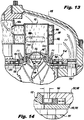
- Fig. 13 shows an enlargement of the area indicated in Fig. 12 , to show the flow of air and gas through the injection ports 154, 156, and 158 for combustion, as indicated by the arrows and combustion lines in Fig. 13.
- Fig. 13 also shows upper and lower plates 118, 120 of bulkhead 110 engaging floating collar seal 160 of slave injector 112.
- Fig. 14 shows a further enlargement of the area indicated in Fig.
- floating collar seal 160 is sandwiched between upper and lower plates 118, 120 of bulkhead 110, and has an axially-sliding engagement to injector 112. In this manner, when the engine cycles through different thermal states, floating collar seals 160 act as floating collars and differential thermal expansion between bulkhead 110 and injectors 112 can be thereby be accommodated without undue stress, fatigue, and the like. Additionally, each floating collar seal 160 seals the respective opening of bulkhead 110 with a slave injector 112 to maintain proper pressure across bulkhead 110.
- One floating collar seal 160 is shown in Fig. 9 separated from the corresponding slave injector 112.
- Each floating collar seal 160 can slide with respect to its slave Injector 112 in the axial direction to accommodate axial thermal contraction and expansion.
- Diverging outlet 126 of master injector 124 includes an integrally formed collar 129 (shown in Fig. 7 ), which accommodates radial thermal expansion much like floating collar seals 160.
- axial thermal expansion and contraction is allowed for master injector 124 by the axial sliding engagement of the cylindrical portion of master injector 124 with diverging outlet 126. Free axial and radial growth is allowed for every injector 112, 124, thanks to the central location of manifold 114 and the ability for the floating collar seals 160 to slide while sealing air flow.
- manifold 114 is mounted to bulkhead 110 by a plurality of springs 162 for accommodating relative thermal expansion and contraction between manifold 114 and bulkhead 110.
- Springs 162 are also shown in Figs. 3 , 4 , and 6 .
- Springs 162 serve as stand offs to permit positioning of master and slave injectors 124, 112 during assembly, and prevent manifold 114 dropping too far into combustor 101 when pressure dome 108 is removed.
- Pressure dome 108 is scaled from inside by its attachment to inlet fitting 116, and therefore permits assembly of master and slave injectors 124 and 112 into their various openings in bulkhead 110 before closing the pressure vessel, i.e. housing 102, during assembly. Once manifold 114 is properly installed, pressure dome 108 can be placed over manifold 114 and bolted into place.
- a method not according to the invention of operating a combustion system such as system 100 for an LCV fuel gas turbine engine.
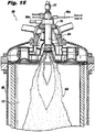
- natural gas is introduced into combustor 101 through inlet 106a of master injector 124 and ignited by igniter 131 to create a master injector plume 164 of ignited natural gas.
- This initial fuel flow can advantageously be in a rich fuel/air ratio, however, those skilled in the art will readily appreciate that any fuel/air ratio can be used from application to application.
- Igniting master injector plume 164 ignites the core area of combustor 101 and establishes a hot zone therein. The power on master injector 124 is then increased until engine idle is accomplished.
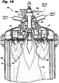
- natural gas is then introduced through slave injectors 112, with each slave injector forming a plume 166 of natural gas that overlaps with plume 164 of master injector 124.
- Injection plumes 166 are radially outward of fuel injected through master injector 124, and overlap or intersect with injection plume 164. Due to the intersecting of master and slave injector plumes 164 and 166, the combusting natural gas from master injector 124 ignites the natural gas from slave injectors 112.
- Master injector 124 is set back upstream by its diverging outlet 126 from the plane of slave injectors 112 (i.e., in bulkhead 110) to allow the flame to grow in diameter before encountering the gas from slave injectors 112, thus enabling rapid ignition and stabilization of the slave injector gasses. Master injector 124 thus acts as a pilot and as a torch.
- Fig. 16 indicates with arrows the flow of natural gas from inlet fitting 116 to slave injectors 112, both stages of which are shown in active operation.
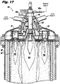
- LCV fuel injection is initiated by proportionally reducing natural gas flow and increasing LCV fuel flow to slave injectors 112 until the engine reaches equilibrium on LCV fuel. This can be accomplished for all slave injectors 112 together, or in separate stages. Gas flow through master injector 124 is then switched from natural gas from inlet 106a to LCV fuel from inlet 106b, as shown in Fig. 18 , to run combustion system 100 exclusively on LCV fuel. This switch to LCV fuel in master injector 124 is proportional, as described above for slave injectors 112, however, the switch could also be instant. As shown in Fig.
- natural gas and LCV fuel have separate inlets 106a and 106b, however a single inlet could be used for both types of fuel.
- Fig. 17 shows that system 100 can operate on multiple different fuels simultaneously. While natural gas and LCV fuel are shown, those skilled in the art will readily appreciate that these are exemplary only, and that any suitable fuels or number of fuels can be used.
- the separate stages of slave injectors 112 can be operated independently to provide stable reduced power capability when operating on LCV fuel. Overall engine power can be reduced by reducing or even eliminating fuel flow to only some of the master and slave injectors 124 and 112 to maintain relatively hot downstream local flame temperatures for stable combustion. The fuel to air ratio on the operational stage should be kept as high as required for stable operation, Natural gas can be added to the LCV gas if required to maintain stability.
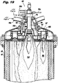
- master injector 124 is shown operating on LCV fuel with first stage slave injectors 112 shut off, but with second stage slave injectors 112 active. The path of fuel through the first stage in manifold 114 is indicated in Fig. 19 by arrows.
- Fig. 19 The path of fuel through the first stage in manifold 114 is indicated in Fig. 19 by arrows.
- Fig. 20 the second stage of slave Injectors is shut off, and the arrows indicate the flow of fuel through the first stage of manifold 114.
- stage of slave injectors could be used at either of the power levels shown in Figs. 19 and 20 .
- Figs. 19 and 20 show the staged down injectors 112 and 124 completely shut off, those skilled in the art will readily appreciate that intermediate power settings can be accomplished with reduced flow, i.e., not completely shut off, in the injectors being staged down.
- the slave flame pattern is advantageously selected to be narrow and off the combustor walls. Those skilled in the art will readily appreciate that any suitable slave flame pattern can be used from a given application.
- master and slave injectors 124 and 112 have been described as injecting gaseous fuels, those skilled in the art will readily appreciate that liquid fuels can also be used.
- atomizers could be included in any of the master and slave injectors to allow for liquid fuel use.
- One exemplary application for this would be where it is desirable to use liquid fuel rather than natural gas for start up.
- any suitable fuels besides natural gas and LCV fuel can be used.
- a six-slave injector configuration is exemplary only, and that any suitable number of master and slave injectors can be used.
- the same basic method of construction could be used in multi-staged configurations of 60 smaller slave injectors, 600 even smaller slave injectors, or any suitable number or size of slave injectors.
- the exemplary single pill-shaped port or perforation for each port 132a, 132b, 150a and 150b While described herein with the exemplary single pill-shaped port or perforation for each port 132a, 132b, 150a and 150b, those skilled in the art will readily appreciate that any suitable shape or number of ports can be used on the respective Injector and manifold components,
- the exemplary system 100 described above includes two combustors 101, however, any suitable number of combustors can be used.
- additional levels for ports 132a, 132b, 150a, and 150b, and additional separator plates can be added for any suitable number of additional stages. More than two subsets or stages of slave injectors can be useful in applications where greater staging or greater numbers of different fuels are used, for example. Moreover, single stage configurations in which there is only one subset or stage of slave injectors can be useful, for example, in applications delivering large amounts of fuel uniformly to multiple nozzles.
Landscapes
- Engineering & Computer Science (AREA)
- Chemical & Material Sciences (AREA)
- Combustion & Propulsion (AREA)
- Mechanical Engineering (AREA)
- General Engineering & Computer Science (AREA)
- Fuel-Injection Apparatus (AREA)
- Gas Burners (AREA)
Description
- The present invention relates to gas turbine engines, and more particularly to a combustion system for a gas turbine engine utilizing low calorific value fuels.
- Gasification of coal, biomass, and other fuels produces fuel gas that can be used for power production. Fuel gas derived from gasification or other such processes is commonly referred to as low calorific value (LCV) fuel because it typically has significantly lower heating values compared to more traditional fuels. Whereas natural gas typically has a heating value of about 37.3 MJ/m3 (1,000 BTU/Ft3) LCV gas can have a heating value on the order of only about 4.84 MJ/m3 (130 BTU/Ft3) and less. LCV gas can be used with or as a replacement for more traditional fuels in applications including internal combustion engines, furnaces, boilers, and the like, In addition to environmental concerns, fluctuating fuel costs and availability drive a growing interest in use of LCV fuels where more traditional fuels, such as natural gas, are typically used.
- While there is growing interest in LCV fuels, the low heating value of LCV fuel Creates obstacles to its more widespread use. Thus there is an ongoing need for improved LCV fuel combustion systems. For example, the use of LCV fuel in an existing, conventional gas turbine engine requires special considerations regarding the fuel injection system. Flammability of LCV fuel gas can be unknown due to variables in the gasification process, so there is typically an unpredictable flameout limit when lowering fuel flow to operate at reduced power. Due to the relatively low heating value, LCV fuel can require 10 to 12 times the volumetric flow rate of natural gas for which the original engine was designed, which can give rise to capacity complications for traditional combustion systems. Typical gasification systems produce LCV fuel through high-temperature processes, and LCV fuel is often supplied directly from the gasification system. The LCV fuel temperature can be significantly hotter than in conventional fuel systems, which can give rise to further thermal management concerns. Additionally, due to the low calorific value, the fuel can present difficulties in terms of start up and flame stabilization.
- Some solutions to these challenges have been proposed, such as using large numbers of small Injectors, and allowing for mixing traditional fuel in with LCV fuel. However, the high flow rates needed to provide an adequate supply of LCV fuel lead to significant pressure drop, which is exacerbated by using large numbers of small injectors. High pressure drop can severely impact overall thermal efficiency for gas turbine engines, for example. Start up and flame stabilization challenges persist in typical LCV fuel injection systems.
- Such conventional methods and systems have generally been considered satisfactory for their intended purpose. However, there is still a need in the art for combustion systems that allow for improved start up, flame stability, and fuel staging. There also remains a need in the art for such systems that are easy to make and use. The present invention provides a solution for these problems.
- The document
EP 1 605 208 A1 discloses a combustion system for a gas turbine engine according to the preamble of claim 1. - According to the invention there is provided a combustion system for a gas turbine engine, comprising:
- a) a housing defining a pressure vessel;
- b) a master injector mounted to the housing for injecting fuel along a central axis (A) defined through the pressure vessel;
- c) a plurality of slave injectors each disposed radially outward of and substantially parallel to the master injector for injecting fuel and air in an injection plume radially outward of fuel injected through the master injector, wherein the master injector and slave injectors are configured and adapted so that, in use, the injection plume of the master injector intersects with the injection plumes of the slave injectors; and
- d) an outlet bulkhead mounted to outlets of each of the master and slave injectors, the outlet bulkhead having an outlet opening sealed around an outlet of each injector;
- These and other features of the system of the subject invention will become more readily apparent to those skilled in the art from the following detailed description of the preferred embodiments taken in conjunction with the drawings.
- So that those skilled in the art to which the subject invention appertains will readily understand how to make and use the system of the subject invention without undue experimentation, preferred embodiments thereof will be described in detail herein below with reference to certain figures, wherein:
-
Fig. 1 is a perspective view of an exemplary embodiment of a gas turbine engine constructed in accordance with the present invention, showing a combustion system with two LCV fuel combustors mounted to the engine; -
Fig. 2 is a perspective view of a portion of one of the combustors ofFig. 1 , showing the pressure dome with the LCV fuel conduits removed from the inlet fittings; -
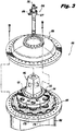
Fig. 3 is a perspective view of a portion of the combustor ofFig. 2 , showing the pressure dame removed with the LCV fuel manifold and injectors mounted to the combustor; -
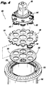
Fig. 4 is an exploded perspective view of a portion of the combustor ofFig. 3 , showing the injectors separated from the upper and lower plates of the combustor bulkhead; -
Fig. 5 is a perspective view of the upper bulkhead plate ofFig. 4 , showing the bulkhead plate from below to reveal the standoffs for maintaining separation between the upper and lower bulkhead plates; -
Fig. 6 is an exploded perspective view of a portion of the combustor ofFig. 4 , showing the inlet fitting separated from the manifold, and showing the diverging outlet of the master injector separated from the manifold; -
Fig. 7 is a cross-sectional side elevation view of the diverging outlet of the master injector ofFig. 6 , showing the swirler ports; -
Fig. 8 is an exploded perspective view of the manifold ofFig. 6 , showing the manifold plates and side walls; -
Fig. 9 is a partially cut-away perspective view of the manifold ofFig. 6 , showing the slave injectors assembled into the manifold; -
Fig. 10 is a cross-sectional perspective view of one of the slave injectors ofFig. 9 ; -
Fig. 11 a is a cross-sectional perspective view of a portion of the slave injector ofFig. 10 , showing the orientations of the converging outer air ports; -
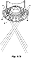
Fig. 11b is a cross-sectional perspective view of a portion of the slave injector ofFig. 10 , showing the orientations of the converging, swirling inner air ports; -
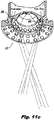
Fig. 11c is a cross-sectional perspective view of a portion of the slave injector ofFig. 10 , showing the orientations of the converging, swirling fuel ports; -
Fig. 12a is a cross-sectional side elevation view of the combustor ofFig. 2 , showing manifold, injectors, igniter, inlet fitting, bulkhead, and pressure dome assembled together; -
Fig. 12b is a cross-sectional side elevation view of a portion of the combustor ofFig. 12a , showing the flow of compressor discharge air into the pressure dome and out the master injector; -
Fig. 13 is a cross-sectional side elevation view of the portion of the combustor indicated inFig. 12 , showing the flow of fuel and air through one of the slave injectors and showing the moveable engagement of one of the slave injectors to the combustor bulkhead; -
Fig. 14 is a cross-sectional side-elevation view of the portion of the combustor bulkhead indicated inFig. 13 , showing the moveable seal sealing around the slave injector between the upper and lower plates of the bulkhead; -
Fig. 15 is a cross-sectional side elevation view of the combustor ofFig. 12 , showing natural gas from the master injector ignited along the centerline of the combustor; -
Fig. 16 is a cross-sectional side elevation view of the combustor ofFig. 15 , showing natural gas from the slave injectors ignited by the combusting natural gas from the master injector along the centerline of the combustor; -
Fig. 17 is a cross-sectional side elevation view of the combustor ofFig. 16 , showing LCV fuel from the slave injectors combusting with natural gas from the master injector; -
Fig. 18 is a cross-sectional side elevation view of the combustor ofFig. 17 , showing all of the injectors operating with LCV fuel; -
Fig. 19 is a cross-sectional side elevation view of the combustor ofFig. 18 , showing some of the slave injectors in a no-flow condition such as when operating at reduced power; and -
Fig. 20 is a cross-sectional side elevation view of the combustor ofFig. 19 , showing reduced power operation with the master injector and some of the slave injectors in a no-flow condition. - Reference will now be made to the drawings wherein like reference numerals identify similar structural features or aspects of the subject invention. For purposes of explanation and illustration, and not limitation, a partial view of an exemplary embodiment of a combustion system constructed in accordance with the invention is shown in
Fig. 1 and is designated generally byreference character 100. Other embodiments of combustion systems, or aspects thereof, are provided inFigs. 2-20 , as will be described. The system of the invention can be used to improve performance of gas turbine engines operating on low calorific value (LCV) fuel. - With reference now to
Fig. 1 , agas turbine engine 10 is shown having acombustion system 100 with twoLCV fuel combustors 101. Eachcombustor 101 includes ahousing 102 defining a pressure vessel for providing combustion products at high pressure to be supplied to the turbine ofengine 10. Pressurized fuel is supplied tocombustor 101 throughinlet conduits Fig. 2 . Each of twoinlet conduits 104a (only one of which is shown inFig. 2 ) is connected to arespective port 105a of inlet fitting 116, and each of two inlet conduits 104b (only one of which shown inFig. 2 ) is connected to a respective port 105b. There are twoports 105a, and two ports 105b, which form high pressure flanges permitting a high volume flow of specified gasses through each opening, with enough flow capacity for LCV fuel operation, for example. One or more of theseports 105a and 105b for high pressure flows can be staged, e.g., reduced or shut off, during engine operation, as described in greater detail below.Ports 105a and 105b can be of any suitable size to accommodate the high volume needed for LCV gas operation, for example, eachport 105a and 105b can be about three inches in diameter. Those skilled in the art will readily appreciate that any suitable number ofports 105a and 105b andinlet conduits 104a and 104b can be used. - The pressure vessel of
housing 102 includes apressure dome 108 which can be removed, as indicated inFig. 3 , to accessbulkhead 110,slave injectors 112, andmanifold 114 without having to remove inlet fitting 116. Central inlet fitting 116 is mounted to an interior rim of the central aperture ofpressure dome 108. as shown inFig. 12 . This arrangement allows the flange of inlet fitting 116 to have self-sealing against the corresponding flange ofpressure dome 108. Therefore, the greater the pressure inpressure dome 108, the tighter the seal and the lighter the flange construction can be. By contrast, if such a joint were instead in tension, more bolts and a heavier flange would be required to prevent warping and leaking. - Referring now to
Fig. 4 ,bulkhead 110 includes anupper plate 118 andlower plate 120 which have openings therethrough to accommodate the outlets ofslave injectors 112 to allow for thermal expansion and contraction, as will be described in greater detail below. The edges ofplates housing 102 andinner combustor wall 103 with radial clearance to allow radial expansion and contraction to accommodate thermal growth mismatches. Separation of upper andlower plates standoffs 122, which are not visible inFig. 4 , but are shown inFig. 5 , which shows the underside ofupper plate 118.Bulkhead 110 can be cooled by backside impingement with air flow through offset holes (not shown) inupper plate 118 andlower plate 120 as needed from application to application. - Referring now to
Figs. 6 and7 , amaster injector 124 is mounted to inlet fitting 116 andmanifold 114 for injecting fuel along a central axis (A) defined throughpressure vessel 102.Master injector 124 includesseparate inlets Master injector 124 includes a divergingoutlet 126, which includes a plurality ofradial slots 128 for injecting a swirling flow of auxiliary air for gas mixing and cooling along the downstream surfaces ofmaster injector 124 to protect against the high temperature combustion withinpressure vessel 102.Master injector 124 also includes a second plurality of swirl bores 125 defined in a cylindrical portion thereof upstream of divergingoutlet 126 for providing auxiliary combustion air and for imparting swirl to the flow frommaster injector 124.Fig. 12b shows the flow of air up from the compressor throughannular passage 172, through the castellation features 170 inbulkhead 110, also shown inFig. 5 , and intopressure dome 108. From here, the air can flow intocombustor 101 through swirl bores 125 andradial slots 128 inmaster injector 124, as well as through the air passages ofslave injectors 112, which will be discussed in greater detail below. - Referring again to
Figs. 6 and7 ,master injector 124 andigniter 131 can be removed from Inlet fitting 116 and manifold 114 independent ofslave injectors 112, providing easy access for maintenance, removal, and/or replacement ofigniter 131.Diverging outlet 126 remains trapped by itsseal 129 between upper andlower plates bulkhead 110 whenmaster injector 124 is removed frommanifold 114 because there is a sliding engagement between the cylindrical portion ofmaster injector 124 and divergingoutlet 126 to accommodate axial thermal expansion and contraction.Master injector 124 includes afuel inlet fixture 127 configured and adapted to selectively supply at least two different types of fuel in a proportional mix tomaster injector 124, such as LCV fuel gas and natural gas. The slave injectors 112 are similarly configured and adapted to selectively inject at least natural gas and LCV fuel gas in a proportional mix, as described below. Anigniter 131 is included ininlet fixture 127 for igniting fuel frommaster Injector 124 during startup. - With reference now to
Figs. 8 and9 ,manifold 114 includespartition plates 130 affixed to acylindrical injector housing 115 ofmanifold 114 through whichmaster injector 124 is housed when assembled.Partition plates 130 are also advantageously welded or otherwise jointed to inlet fitting 116 to separate flows from different inlets to different injectors as will be described in greater detail below. An inner cylindrical wall 134 is mounted topartition plates 130 and includes two pill-shapedports 132a and 132b. Opposed to inner cylindrical wall 134 is outercylindrical wall 136. Uppermanifold plate 138 andlower manifold plate 140 are mounted to inner and outercylindrical walls 134, 136 to form an annular manifold space.Manifold separator plate 142 is mounted to inner and outercylindrical walls 134, 136 at an elevation about half-way between upper and lowermanifold plates Separator plate 142 divides the annular manifold space ofmanifold 114 into anupper duct 144 and alower duct 146.Manifold plates Fig. 8 , for accommodatingslave injectors 112 as shown inFig. 9 . Withslave injectors 112 mounted inbores 148,slave injectors 112 stiffen manifold 114, and the arrangement ofslave injectors 112 around acentral master injector 124 provides a compact multi-stage gas inlet fitting forsystem 100. - With continued reference to
Fig. 9 , each slave injector has a single pill-shaped inlet perforation orport 150a or 150b.Ports 150a are in fluid communication withupper duct 144 of the annular manifold space, which is in fluid communication withport 132a (shown inFig. 8 ) of inner cylindrical wall 134. Ports 150b are in fluid communication withlower duct 146 of the annular manifold space, which is in fluid communication with port 132b (shown inFig. 8 ) of inner cylindrical wall 134.Ports 132a and 132b (Shown inFig. 8 ) of inner cylindrical wall 134 are on opposite sides ofpartition plates 130, which divide the space betweencylindrical injector housing 115 and inlet fitting 116 into twomanifold spaces 152a and 152b in fluid communication withports 132a and 132b, respectively. -
Inlet ports 150a are at a different, axially spaced apart level from the level of inlet ports 150b. As oriented inFig. 9 ,inlet ports 150a are at a higher level in fluid communication withupper duct 144 of the annular manifold space, and inlet ports 150b are at a lower level in fluid communication withlower duct 146 of the annular manifold space. Three of the injectors haveinlet ports 150a, and the other threeslave injectors 112 have inlet ports 150b. Therefore, eachslave injector 112 is in fluid communication with only one of upper andlower ducts - With inlet fitting 116 in place as shown in
Fig. 2 ,manifold 114 separates fuel flow toslave injectors 112 into two separate stages capable of being controlled externally for independent operation. This separation allows for reduced power levels, as described in greater detail below. The flow path for the first stage includesinlet conduit 104a (shown inFig. 2 ),port 105a of inlet fitting 116 (shown inFig. 6 ),manifold space 152a (shown inFig. 9 ),port 132a in inner cylindrical wall 134 (shown inFig. 8 ),upper duct 144 of the annular manifold space inmanifold 114, pill-shapedports 150a in firststage slave injectors 112, and through the outlets of the three firststage slave injectors 112. The flow path for the second stage includes inlet conduit 104b (shown inFig. 2 ), port 105b of inlet fitting 116 (shown inFig. 6 ), manifold space 152b (shown inFig. 9 ), port 132b in inner cylindrical wall 134 (shown inFig, 9 ),lower duct 146 of the annular manifold space inmanifold 114, pill-shaped ports 150b in firststage slave injectors 112, and through the outlets of the three secondstage slave injectors 112.Manifold 114 is configured to separately distribute fuel to two subsets of the slave injectors. The slave injectors 112 of each stage can selectively inject natural gas and LCV fuel gas in a proportional mix, much likemaster injector 124. The entire manifold assembly is installed withinpressure vessel 102, reducing pressure and temperature gradients betweenmanifold 114 and the external environment. - Those skilled in the art will readily appreciate that the configuration described herein with three slave injectors in each of two stages is exemplary only. Any suitable number of injectors can be used in any suitable number of stages, including configurations where each stage has a different number of injectors.
- Referring now to
Fig. 10 , eachslave Injector 112 includes three sets of injection ports. The innermost set ofinjection ports 154 inject fuel fromport 150a (or 150b if applicable) for combustion.Intermediate injection ports 156 andouter injection ports 158 inject air from within pressure dome 108 (seeFig. 12b ). As shown inFig. 11a ,outer injection ports 158 are aligned to inject a converging, non-swirling flow of air, which converges into the flows of air and gas fromports Fig. 11b ,intermediate injection ports 156 are aligned to inject a converging, swirling flow of air, which intersects the converging, swirling flow frominjection ports 154, which is indicated inFig. 11c . In this manner, the fuel is given a high, divergent swirl. Inner air jets are given convergent swirl to mix with fuel close toinjector 112 in a rich bum fashion. The outer swirl, i.e., fromports 158, is less convergent, but confines the flow and provides lean bum out action. Those skilled in the art will readily appreciate that any other suitable flow port configuration can be used from application to application. - With reference now to
Fig. 12a , eachslave injector 112 is disposed radially outward of and substantially parallel tomaster injector 124.Master injector 124 is shown solid, rather than in cross-section inFig. 12a , withigniter 131 indicated in hidden lines.Fig. 13 shows an enlargement of the area indicated inFig. 12 , to show the flow of air and gas through theinjection ports Fig. 13. Fig. 13 also shows upper andlower plates bulkhead 110 engaging floatingcollar seal 160 ofslave injector 112.Fig. 14 shows a further enlargement of the area indicated inFig. 13 , in which the moveable engagement of floatingcollar seal 160 with respect tobulkhead 110 is indicated with arrows. Floatingcollar seal 160 is sandwiched between upper andlower plates bulkhead 110, and has an axially-sliding engagement toinjector 112. In this manner, when the engine cycles through different thermal states, floating collar seals 160 act as floating collars and differential thermal expansion betweenbulkhead 110 andinjectors 112 can be thereby be accommodated without undue stress, fatigue, and the like. Additionally, each floatingcollar seal 160 seals the respective opening ofbulkhead 110 with aslave injector 112 to maintain proper pressure acrossbulkhead 110. One floatingcollar seal 160 is shown inFig. 9 separated from thecorresponding slave injector 112. Each floatingcollar seal 160 can slide with respect to itsslave Injector 112 in the axial direction to accommodate axial thermal contraction and expansion.Diverging outlet 126 ofmaster injector 124 includes an integrally formed collar 129 (shown inFig. 7 ), which accommodates radial thermal expansion much like floating collar seals 160. Similarly, axial thermal expansion and contraction is allowed formaster injector 124 by the axial sliding engagement of the cylindrical portion ofmaster injector 124 with divergingoutlet 126. Free axial and radial growth is allowed for everyinjector manifold 114 and the ability for the floating collar seals 160 to slide while sealing air flow. - With continued reference to
Fig. 12a ,manifold 114 is mounted tobulkhead 110 by a plurality ofsprings 162 for accommodating relative thermal expansion and contraction betweenmanifold 114 andbulkhead 110.Springs 162 are also shown inFigs. 3 ,4 , and6 .Springs 162 serve as stand offs to permit positioning of master andslave injectors combustor 101 whenpressure dome 108 is removed.Pressure dome 108 is scaled from inside by its attachment to inlet fitting 116, and therefore permits assembly of master andslave injectors bulkhead 110 before closing the pressure vessel, i.e.housing 102, during assembly. Oncemanifold 114 is properly installed,pressure dome 108 can be placed overmanifold 114 and bolted into place. - With reference now to
Fig. 15 , also provided is a method not according to the invention of operating a combustion system, such assystem 100 for an LCV fuel gas turbine engine. To initiate combustion, as during startup of the engine, natural gas is introduced intocombustor 101 throughinlet 106a ofmaster injector 124 and ignited byigniter 131 to create amaster injector plume 164 of ignited natural gas. This initial fuel flow can advantageously be in a rich fuel/air ratio, however, those skilled in the art will readily appreciate that any fuel/air ratio can be used from application to application. Ignitingmaster injector plume 164 ignites the core area ofcombustor 101 and establishes a hot zone therein. The power onmaster injector 124 is then increased until engine idle is accomplished. - Referring now to
Fig. 16 , natural gas is then introduced throughslave injectors 112, with each slave injector forming aplume 166 of natural gas that overlaps withplume 164 ofmaster injector 124. This bringssystem 100 up to full power, or other suitable high power condition.Injection plumes 166 are radially outward of fuel injected throughmaster injector 124, and overlap or intersect withinjection plume 164. Due to the intersecting of master andslave injector plumes master injector 124 ignites the natural gas fromslave injectors 112.Master injector 124 is set back upstream by its divergingoutlet 126 from the plane of slave injectors 112 (i.e., in bulkhead 110) to allow the flame to grow in diameter before encountering the gas fromslave injectors 112, thus enabling rapid ignition and stabilization of the slave injector gasses.Master injector 124 thus acts as a pilot and as a torch.Fig. 16 indicates with arrows the flow of natural gas from inlet fitting 116 toslave injectors 112, both stages of which are shown in active operation. - Referring now to
Fig. 17 , LCV fuel injection is initiated by proportionally reducing natural gas flow and increasing LCV fuel flow toslave injectors 112 until the engine reaches equilibrium on LCV fuel. This can be accomplished for allslave injectors 112 together, or in separate stages. Gas flow throughmaster injector 124 is then switched from natural gas frominlet 106a to LCV fuel frominlet 106b, as shown inFig. 18 , to runcombustion system 100 exclusively on LCV fuel. This switch to LCV fuel inmaster injector 124 is proportional, as described above forslave injectors 112, however, the switch could also be instant. As shown inFig. 18 , natural gas and LCV fuel haveseparate inlets Fig. 17 shows thatsystem 100 can operate on multiple different fuels simultaneously. While natural gas and LCV fuel are shown, those skilled in the art will readily appreciate that these are exemplary only, and that any suitable fuels or number of fuels can be used. - Referring now to
Fig. 19 , the separate stages ofslave injectors 112 can be operated independently to provide stable reduced power capability when operating on LCV fuel. Overall engine power can be reduced by reducing or even eliminating fuel flow to only some of the master andslave injectors Fig. 19 ,master injector 124 is shown operating on LCV fuel with firststage slave injectors 112 shut off, but with secondstage slave injectors 112 active. The path of fuel through the first stage inmanifold 114 is indicated inFig. 19 by arrows. InFig. 20 , another even lower power setting is shown in which flow tomaster injector 124 is completely shut off, but one stage ofslave injectors 112 operational. Rather than reducing flow on all injectors, reducing flow on only one stage allows the flame to remain hot downstream of the operating injectors, reducing the risk of flame out that could occur if the flame were allowed to get too cool globally. - In
Fig. 20 , the second stage of slave Injectors is shut off, and the arrows indicate the flow of fuel through the first stage ofmanifold 114. Those skilled in the art will readily appreciate that either stage of slave injectors could be used at either of the power levels shown inFigs. 19 and20 . Moreover, whileFigs. 19 and20 show the staged downinjectors Fig. 20 , the slave flame pattern is advantageously selected to be narrow and off the combustor walls. Those skilled in the art will readily appreciate that any suitable slave flame pattern can be used from a given application. - While master and
slave injectors - Those skilled in the art will readily appreciate that a six-slave injector configuration is exemplary only, and that any suitable number of master and slave injectors can be used. For example, the same basic method of construction could be used in multi-staged configurations of 60 smaller slave injectors, 600 even smaller slave injectors, or any suitable number or size of slave injectors. While described herein with the exemplary single pill-shaped port or perforation for each
port exemplary system 100 described above includes twocombustors 101, however, any suitable number of combustors can be used. Additionally, while described herein in the exemplary context of two manifold stages, additional levels forports e.g. plates 142, 130) can be added for any suitable number of additional stages. More than two subsets or stages of slave injectors can be useful in applications where greater staging or greater numbers of different fuels are used, for example. Moreover, single stage configurations in which there is only one subset or stage of slave injectors can be useful, for example, in applications delivering large amounts of fuel uniformly to multiple nozzles. - The system of the present invention, as described above and shown in the drawings, provides for a low calorific value fuel combustion system with superior properties including improved assembly, improved engine start up, and improved stability in reduced power operation compared to traditional systems. While the apparatus of the subject invention has been shown and described with reference to preferred embodiments, those skilled in the art will readily appreciate that changes and/or modifications may be made thereto without departing from the scope of the subject invention as defined in claim 1.
characterised in that each floating collar seal is partially sandwiched between an upper plate of the outlet bulkhead and a lower plate of the outlet bulkhead mounted to the upper plate of the outlet bulkhead.
Claims (1)
- A combustion system (100) for a gas turbine engine, comprising:a) a housing (102) defining a pressure vessel;b) a master injector (124) mounted to the housing (102) for injecting fuel along a central axis (A) defined through the pressure vessel;c) a plurality of slave injectors (112) each disposed radially outward of and substantially parallel to the master injector (124) for injecting fuel and air in an injection plume (166) radially outward of fuel injected through the master injector (124), wherein the master injector (124) and slave injectors (112) are configured and adapted so that, in use, the injection plume (164) of the master injector (124) intersects with the injection plumes (166) of the slave injectors (112), andd) an outlet bulkhead (110) mounted to outlets of each of the master (124) and slave injectors (112), the outlet bulkhead (110) having an outlet opening sealed around an outlet of each injector (112, 124);wherein a floating collar seal (160) is movably mounted to each outlet opening to seal between the outlet of each respective injector (112, 124) and the outlet bulkhead (110) to accommodate relative thermal expansion and contraction of the injectors (112, 124) and outlet bulkhead (110); characterised in that each floating collar seal (160) is partially sandwiched between an upper plate (118) of the outlet bulkhead (110) and a lower plate (120) of the outlet bulkhead (110) mounted to the upper plate (118) of the outlet bulkhead (110).
Applications Claiming Priority (2)
| Application Number | Priority Date | Filing Date | Title |
|---|---|---|---|
| US12/954,008 US8899048B2 (en) | 2010-11-24 | 2010-11-24 | Low calorific value fuel combustion systems for gas turbine engines |
| EP11250766A EP2458284A3 (en) | 2010-11-24 | 2011-09-09 | Low calorific value fuel combustion systems for gas turbine engines |
Related Parent Applications (1)
| Application Number | Title | Priority Date | Filing Date |
|---|---|---|---|
| EP11250766A Division EP2458284A3 (en) | 2010-11-24 | 2011-09-09 | Low calorific value fuel combustion systems for gas turbine engines |
Publications (3)
| Publication Number | Publication Date |
|---|---|
| EP2957834A2 EP2957834A2 (en) | 2015-12-23 |
| EP2957834A3 EP2957834A3 (en) | 2016-03-30 |
| EP2957834B1 true EP2957834B1 (en) | 2019-02-27 |
Family
ID=44785737
Family Applications (2)
| Application Number | Title | Priority Date | Filing Date |
|---|---|---|---|
| EP15172213.9A Active EP2957834B1 (en) | 2010-11-24 | 2011-09-09 | Low calorific value fuel combustion system for gas turbine engines |
| EP11250766A Withdrawn EP2458284A3 (en) | 2010-11-24 | 2011-09-09 | Low calorific value fuel combustion systems for gas turbine engines |
Family Applications After (1)
| Application Number | Title | Priority Date | Filing Date |
|---|---|---|---|
| EP11250766A Withdrawn EP2458284A3 (en) | 2010-11-24 | 2011-09-09 | Low calorific value fuel combustion systems for gas turbine engines |
Country Status (2)
| Country | Link |
|---|---|
| US (1) | US8899048B2 (en) |
| EP (2) | EP2957834B1 (en) |
Families Citing this family (30)
| Publication number | Priority date | Publication date | Assignee | Title |
|---|---|---|---|---|
| US8769955B2 (en) | 2010-06-02 | 2014-07-08 | Siemens Energy, Inc. | Self-regulating fuel staging port for turbine combustor |
| EP2551470A1 (en) * | 2011-07-26 | 2013-01-30 | Siemens Aktiengesellschaft | Method for starting a stationary gas turbine |
| EP2719953A3 (en) * | 2012-10-09 | 2018-01-03 | Delavan Inc. | Multipoint injectors with auxiliary stage |
| WO2014081334A1 (en) * | 2012-11-21 | 2014-05-30 | General Electric Company | Anti-coking liquid fuel cartridge |
| RU2618801C2 (en) * | 2013-01-10 | 2017-05-11 | Дженерал Электрик Компани | Fuel nozzle, end fuel nozzle unit, and gas turbine |
| GB201303428D0 (en) | 2013-02-27 | 2013-04-10 | Rolls Royce Plc | A vane structure and a method of manufacturing a vane structure |
| US9377202B2 (en) | 2013-03-15 | 2016-06-28 | General Electric Company | System and method for fuel blending and control in gas turbines |
| US9382850B2 (en) | 2013-03-21 | 2016-07-05 | General Electric Company | System and method for controlled fuel blending in gas turbines |
| WO2014204449A1 (en) | 2013-06-18 | 2014-12-24 | Woodward, Inc. | Gas turbine engine flow regulating |
| US9482433B2 (en) | 2013-11-11 | 2016-11-01 | Woodward, Inc. | Multi-swirler fuel/air mixer with centralized fuel injection |
| US9587833B2 (en) | 2014-01-29 | 2017-03-07 | Woodward, Inc. | Combustor with staged, axially offset combustion |
| US11619388B2 (en) * | 2017-12-21 | 2023-04-04 | Collins Engine Nozzles, Inc. | Dual fuel gas turbine engine pilot nozzles |
| DE102018222890A1 (en) * | 2018-12-21 | 2020-06-25 | Rolls-Royce Deutschland Ltd & Co Kg | Engine assembly and operating procedures |
| US11156164B2 (en) | 2019-05-21 | 2021-10-26 | General Electric Company | System and method for high frequency accoustic dampers with caps |
| US11174792B2 (en) | 2019-05-21 | 2021-11-16 | General Electric Company | System and method for high frequency acoustic dampers with baffles |
| FR3105818B1 (en) * | 2019-12-31 | 2022-08-26 | Fives Pillard | Low NOx Burner |
| GB2592267A (en) * | 2020-02-24 | 2021-08-25 | Altair Uk Ltd | Pulse nozzle for filter cleaning systems |
| US11608783B2 (en) | 2020-11-04 | 2023-03-21 | Delavan, Inc. | Surface igniter cooling system |
| US11692488B2 (en) * | 2020-11-04 | 2023-07-04 | Delavan Inc. | Torch igniter cooling system |
| US11473505B2 (en) | 2020-11-04 | 2022-10-18 | Delavan Inc. | Torch igniter cooling system |
| GB202017854D0 (en) * | 2020-11-12 | 2020-12-30 | Univ College Cardiff Consultants Ltd | Combustor systems and methods |
| US11635027B2 (en) | 2020-11-18 | 2023-04-25 | Collins Engine Nozzles, Inc. | Fuel systems for torch ignition devices |
| US11421602B2 (en) | 2020-12-16 | 2022-08-23 | Delavan Inc. | Continuous ignition device exhaust manifold |
| US11635210B2 (en) | 2020-12-17 | 2023-04-25 | Collins Engine Nozzles, Inc. | Conformal and flexible woven heat shields for gas turbine engine components |
| US11486309B2 (en) | 2020-12-17 | 2022-11-01 | Delavan Inc. | Axially oriented internally mounted continuous ignition device: removable hot surface igniter |
| US12092333B2 (en) | 2020-12-17 | 2024-09-17 | Collins Engine Nozzles, Inc. | Radially oriented internally mounted continuous ignition device |
| US11754289B2 (en) | 2020-12-17 | 2023-09-12 | Delavan, Inc. | Axially oriented internally mounted continuous ignition device: removable nozzle |
| US11209164B1 (en) | 2020-12-18 | 2021-12-28 | Delavan Inc. | Fuel injector systems for torch igniters |
| US11680528B2 (en) | 2020-12-18 | 2023-06-20 | Delavan Inc. | Internally-mounted torch igniters with removable igniter heads |
| US12215866B2 (en) | 2022-02-18 | 2025-02-04 | General Electric Company | Combustor for a turbine engine having a fuel-air mixer including a set of mixing passages |
Family Cites Families (37)
| Publication number | Priority date | Publication date | Assignee | Title |
|---|---|---|---|---|
| US2607193A (en) | 1947-10-25 | 1952-08-19 | Curtiss Wright Corp | Annular combustion chamber with multiple notched fuel nozzles |
| US3680793A (en) | 1970-11-09 | 1972-08-01 | Delavan Manufacturing Co | Eccentric spiral swirl chamber nozzle |
| US4100733A (en) * | 1976-10-04 | 1978-07-18 | United Technologies Corporation | Premix combustor |
| JPS57187531A (en) | 1981-05-12 | 1982-11-18 | Hitachi Ltd | Low nox gas turbine burner |
| JP2894861B2 (en) | 1991-04-18 | 1999-05-24 | 株式会社日立製作所 | Control device for gas turbine combustor |
| US5409169A (en) | 1991-06-19 | 1995-04-25 | Hitachi America, Ltd. | Air-assist fuel injection system |
| US5235814A (en) | 1991-08-01 | 1993-08-17 | General Electric Company | Flashback resistant fuel staged premixed combustor |
| US5361586A (en) | 1993-04-15 | 1994-11-08 | Westinghouse Electric Corporation | Gas turbine ultra low NOx combustor |
| US5359847B1 (en) * | 1993-06-01 | 1996-04-09 | Westinghouse Electric Corp | Dual fuel ultra-flow nox combustor |
| GB2319078B (en) | 1996-11-08 | 1999-11-03 | Europ Gas Turbines Ltd | Combustor arrangement |
| US5983642A (en) | 1997-10-13 | 1999-11-16 | Siemens Westinghouse Power Corporation | Combustor with two stage primary fuel tube with concentric members and flow regulating |
| JPH11344224A (en) * | 1998-06-02 | 1999-12-14 | Hitachi Ltd | Gas turbine combustor |
| US6092363A (en) | 1998-06-19 | 2000-07-25 | Siemens Westinghouse Power Corporation | Low Nox combustor having dual fuel injection system |
| US6533954B2 (en) | 2000-02-28 | 2003-03-18 | Parker-Hannifin Corporation | Integrated fluid injection air mixing system |
| US6363726B1 (en) | 2000-09-29 | 2002-04-02 | General Electric Company | Mixer having multiple swirlers |
| US6688534B2 (en) | 2001-03-07 | 2004-02-10 | Delavan Inc | Air assist fuel nozzle |
| US6622488B2 (en) | 2001-03-21 | 2003-09-23 | Parker-Hannifin Corporation | Pure airblast nozzle |
| JP2002349854A (en) | 2001-05-30 | 2002-12-04 | Mitsubishi Heavy Ind Ltd | Gas turbine combustor pilot nozzle and feed line converter |
| US6755024B1 (en) | 2001-08-23 | 2004-06-29 | Delavan Inc. | Multiplex injector |
| US6854670B2 (en) | 2002-05-17 | 2005-02-15 | Keihin Corporation | Fuel injection valve |
| US6772583B2 (en) | 2002-09-11 | 2004-08-10 | Siemens Westinghouse Power Corporation | Can combustor for a gas turbine engine |
| US6962055B2 (en) | 2002-09-27 | 2005-11-08 | United Technologies Corporation | Multi-point staging strategy for low emission and stable combustion |
| US6863228B2 (en) | 2002-09-30 | 2005-03-08 | Delavan Inc. | Discrete jet atomizer |
| US6931853B2 (en) | 2002-11-19 | 2005-08-23 | Siemens Westinghouse Power Corporation | Gas turbine combustor having staged burners with dissimilar mixing passage geometries |
| US6871488B2 (en) | 2002-12-17 | 2005-03-29 | Pratt & Whitney Canada Corp. | Natural gas fuel nozzle for gas turbine engine |
| US7284378B2 (en) | 2004-06-04 | 2007-10-23 | General Electric Company | Methods and apparatus for low emission gas turbine energy generation |
| US7174717B2 (en) | 2003-12-24 | 2007-02-13 | Pratt & Whitney Canada Corp. | Helical channel fuel distributor and method |
| US7533531B2 (en) | 2005-04-01 | 2009-05-19 | Pratt & Whitney Canada Corp. | Internal fuel manifold with airblast nozzles |
| US7647779B2 (en) * | 2005-04-27 | 2010-01-19 | United Technologies Corporation | Compliant metal support for ceramic combustor liner in a gas turbine engine |
| US7520134B2 (en) | 2006-09-29 | 2009-04-21 | General Electric Company | Methods and apparatus for injecting fluids into a turbine engine |
| FR2911667B1 (en) * | 2007-01-23 | 2009-10-02 | Snecma Sa | FUEL INJECTION SYSTEM WITH DOUBLE INJECTOR. |
| US7926178B2 (en) | 2007-11-30 | 2011-04-19 | Delavan Inc | Method of fuel nozzle construction |
| US7926282B2 (en) | 2008-03-04 | 2011-04-19 | Delavan Inc | Pure air blast fuel injector |
| US20090255258A1 (en) | 2008-04-11 | 2009-10-15 | Delavan Inc | Pre-filming air-blast fuel injector having a reduced hydraulic spray angle |
| US8220272B2 (en) | 2008-12-04 | 2012-07-17 | General Electric Company | Combustor housing for combustion of low-BTU fuel gases and methods of making and using the same |
| US20100192582A1 (en) | 2009-02-04 | 2010-08-05 | Robert Bland | Combustor nozzle |
| US8313046B2 (en) | 2009-08-04 | 2012-11-20 | Delavan Inc | Multi-point injector ring |
-
2010
- 2010-11-24 US US12/954,008 patent/US8899048B2/en active Active
-
2011
- 2011-09-09 EP EP15172213.9A patent/EP2957834B1/en active Active
- 2011-09-09 EP EP11250766A patent/EP2458284A3/en not_active Withdrawn
Non-Patent Citations (1)
| Title |
|---|
| None * |
Also Published As
| Publication number | Publication date |
|---|---|
| US8899048B2 (en) | 2014-12-02 |
| EP2957834A3 (en) | 2016-03-30 |
| EP2458284A2 (en) | 2012-05-30 |
| EP2458284A3 (en) | 2012-09-12 |
| EP2957834A2 (en) | 2015-12-23 |
| US20120125008A1 (en) | 2012-05-24 |
Similar Documents
| Publication | Publication Date | Title |
|---|---|---|
| US8899048B2 (en) | Low calorific value fuel combustion systems for gas turbine engines | |
| CN209726265U (en) | Ejection assemblies for gas turbine combustor | |
| EP4220014B1 (en) | Combustion system with panel fuel injector | |
| US11428413B2 (en) | Fuel injection module for segmented annular combustion system | |
| US10830442B2 (en) | Segmented annular combustion system with dual fuel capability | |
| US10584876B2 (en) | Micro-channel cooling of integrated combustor nozzle of a segmented annular combustion system | |
| US10584880B2 (en) | Mounting of integrated combustor nozzles in a segmented annular combustion system | |
| US10563869B2 (en) | Operation and turndown of a segmented annular combustion system | |
| US10605459B2 (en) | Integrated combustor nozzle for a segmented annular combustion system | |
| JP7337497B2 (en) | Axial fuel staging system for gas turbine combustors | |
| US10520194B2 (en) | Radially stacked fuel injection module for a segmented annular combustion system | |
| US10641491B2 (en) | Cooling of integrated combustor nozzle of segmented annular combustion system | |
| CN112594735B (en) | Gas Turbine Burners | |
| EP3211318B1 (en) | Gas-only cartridge for a premix fuel nozzle | |
| JP2019105438A (en) | Thimble assembly for introducing cross-flow into secondary combustion zone | |
| JP2021096016A (en) | Gas turbine combustor | |
| US20210095850A1 (en) | Gas Turbine Combustor |
Legal Events
| Date | Code | Title | Description |
|---|---|---|---|
| PUAI | Public reference made under article 153(3) epc to a published international application that has entered the european phase |
Free format text: ORIGINAL CODE: 0009012 |
|
| AC | Divisional application: reference to earlier application |
Ref document number: 2458284 Country of ref document: EP Kind code of ref document: P |
|
| AK | Designated contracting states |
Kind code of ref document: A2 Designated state(s): AL AT BE BG CH CY CZ DE DK EE ES FI FR GB GR HR HU IE IS IT LI LT LU LV MC MK MT NL NO PL PT RO RS SE SI SK SM TR |
|
| PUAL | Search report despatched |
Free format text: ORIGINAL CODE: 0009013 |
|
| AK | Designated contracting states |
Kind code of ref document: A3 Designated state(s): AL AT BE BG CH CY CZ DE DK EE ES FI FR GB GR HR HU IE IS IT LI LT LU LV MC MK MT NL NO PL PT RO RS SE SI SK SM TR |
|
| RIC1 | Information provided on ipc code assigned before grant |
Ipc: F23R 3/36 20060101ALI20160222BHEP Ipc: F23R 3/54 20060101ALI20160222BHEP Ipc: F23R 3/44 20060101ALI20160222BHEP Ipc: F23R 3/34 20060101AFI20160222BHEP |
|
| 17P | Request for examination filed |
Effective date: 20160930 |
|
| RBV | Designated contracting states (corrected) |
Designated state(s): AL AT BE BG CH CY CZ DE DK EE ES FI FR GB GR HR HU IE IS IT LI LT LU LV MC MK MT NL NO PL PT RO RS SE SI SK SM TR |
|
| GRAP | Despatch of communication of intention to grant a patent |
Free format text: ORIGINAL CODE: EPIDOSNIGR1 |
|
| STAA | Information on the status of an ep patent application or granted ep patent |
Free format text: STATUS: GRANT OF PATENT IS INTENDED |
|
| INTG | Intention to grant announced |
Effective date: 20180903 |
|
| GRAS | Grant fee paid |
Free format text: ORIGINAL CODE: EPIDOSNIGR3 |
|
| GRAA | (expected) grant |
Free format text: ORIGINAL CODE: 0009210 |
|
| STAA | Information on the status of an ep patent application or granted ep patent |
Free format text: STATUS: THE PATENT HAS BEEN GRANTED |
|
| AC | Divisional application: reference to earlier application |
Ref document number: 2458284 Country of ref document: EP Kind code of ref document: P |
|
| AK | Designated contracting states |
Kind code of ref document: B1 Designated state(s): AL AT BE BG CH CY CZ DE DK EE ES FI FR GB GR HR HU IE IS IT LI LT LU LV MC MK MT NL NO PL PT RO RS SE SI SK SM TR |
|
| REG | Reference to a national code |
Ref country code: GB Ref legal event code: FG4D |
|
| REG | Reference to a national code |
Ref country code: CH Ref legal event code: EP |
|
| REG | Reference to a national code |
Ref country code: AT Ref legal event code: REF Ref document number: 1101906 Country of ref document: AT Kind code of ref document: T Effective date: 20190315 |
|
| REG | Reference to a national code |
Ref country code: IE Ref legal event code: FG4D |
|
| REG | Reference to a national code |
Ref country code: DE Ref legal event code: R096 Ref document number: 602011056781 Country of ref document: DE |
|
| REG | Reference to a national code |
Ref country code: NL Ref legal event code: MP Effective date: 20190227 |
|
| REG | Reference to a national code |
Ref country code: LT Ref legal event code: MG4D |
|
| PG25 | Lapsed in a contracting state [announced via postgrant information from national office to epo] |
Ref country code: NO Free format text: LAPSE BECAUSE OF FAILURE TO SUBMIT A TRANSLATION OF THE DESCRIPTION OR TO PAY THE FEE WITHIN THE PRESCRIBED TIME-LIMIT Effective date: 20190527 Ref country code: SE Free format text: LAPSE BECAUSE OF FAILURE TO SUBMIT A TRANSLATION OF THE DESCRIPTION OR TO PAY THE FEE WITHIN THE PRESCRIBED TIME-LIMIT Effective date: 20190227 Ref country code: PT Free format text: LAPSE BECAUSE OF FAILURE TO SUBMIT A TRANSLATION OF THE DESCRIPTION OR TO PAY THE FEE WITHIN THE PRESCRIBED TIME-LIMIT Effective date: 20190627 Ref country code: FI Free format text: LAPSE BECAUSE OF FAILURE TO SUBMIT A TRANSLATION OF THE DESCRIPTION OR TO PAY THE FEE WITHIN THE PRESCRIBED TIME-LIMIT Effective date: 20190227 Ref country code: LT Free format text: LAPSE BECAUSE OF FAILURE TO SUBMIT A TRANSLATION OF THE DESCRIPTION OR TO PAY THE FEE WITHIN THE PRESCRIBED TIME-LIMIT Effective date: 20190227 |
|
| PG25 | Lapsed in a contracting state [announced via postgrant information from national office to epo] |
Ref country code: NL Free format text: LAPSE BECAUSE OF FAILURE TO SUBMIT A TRANSLATION OF THE DESCRIPTION OR TO PAY THE FEE WITHIN THE PRESCRIBED TIME-LIMIT Effective date: 20190227 Ref country code: HR Free format text: LAPSE BECAUSE OF FAILURE TO SUBMIT A TRANSLATION OF THE DESCRIPTION OR TO PAY THE FEE WITHIN THE PRESCRIBED TIME-LIMIT Effective date: 20190227 Ref country code: GR Free format text: LAPSE BECAUSE OF FAILURE TO SUBMIT A TRANSLATION OF THE DESCRIPTION OR TO PAY THE FEE WITHIN THE PRESCRIBED TIME-LIMIT Effective date: 20190528 Ref country code: LV Free format text: LAPSE BECAUSE OF FAILURE TO SUBMIT A TRANSLATION OF THE DESCRIPTION OR TO PAY THE FEE WITHIN THE PRESCRIBED TIME-LIMIT Effective date: 20190227 Ref country code: IS Free format text: LAPSE BECAUSE OF FAILURE TO SUBMIT A TRANSLATION OF THE DESCRIPTION OR TO PAY THE FEE WITHIN THE PRESCRIBED TIME-LIMIT Effective date: 20190627 Ref country code: BG Free format text: LAPSE BECAUSE OF FAILURE TO SUBMIT A TRANSLATION OF THE DESCRIPTION OR TO PAY THE FEE WITHIN THE PRESCRIBED TIME-LIMIT Effective date: 20190527 Ref country code: RS Free format text: LAPSE BECAUSE OF FAILURE TO SUBMIT A TRANSLATION OF THE DESCRIPTION OR TO PAY THE FEE WITHIN THE PRESCRIBED TIME-LIMIT Effective date: 20190227 |
|
| REG | Reference to a national code |
Ref country code: AT Ref legal event code: MK05 Ref document number: 1101906 Country of ref document: AT Kind code of ref document: T Effective date: 20190227 |
|
| PG25 | Lapsed in a contracting state [announced via postgrant information from national office to epo] |
Ref country code: ES Free format text: LAPSE BECAUSE OF FAILURE TO SUBMIT A TRANSLATION OF THE DESCRIPTION OR TO PAY THE FEE WITHIN THE PRESCRIBED TIME-LIMIT Effective date: 20190227 Ref country code: AL Free format text: LAPSE BECAUSE OF FAILURE TO SUBMIT A TRANSLATION OF THE DESCRIPTION OR TO PAY THE FEE WITHIN THE PRESCRIBED TIME-LIMIT Effective date: 20190227 Ref country code: CZ Free format text: LAPSE BECAUSE OF FAILURE TO SUBMIT A TRANSLATION OF THE DESCRIPTION OR TO PAY THE FEE WITHIN THE PRESCRIBED TIME-LIMIT Effective date: 20190227 Ref country code: DK Free format text: LAPSE BECAUSE OF FAILURE TO SUBMIT A TRANSLATION OF THE DESCRIPTION OR TO PAY THE FEE WITHIN THE PRESCRIBED TIME-LIMIT Effective date: 20190227 Ref country code: RO Free format text: LAPSE BECAUSE OF FAILURE TO SUBMIT A TRANSLATION OF THE DESCRIPTION OR TO PAY THE FEE WITHIN THE PRESCRIBED TIME-LIMIT Effective date: 20190227 Ref country code: IT Free format text: LAPSE BECAUSE OF FAILURE TO SUBMIT A TRANSLATION OF THE DESCRIPTION OR TO PAY THE FEE WITHIN THE PRESCRIBED TIME-LIMIT Effective date: 20190227 Ref country code: EE Free format text: LAPSE BECAUSE OF FAILURE TO SUBMIT A TRANSLATION OF THE DESCRIPTION OR TO PAY THE FEE WITHIN THE PRESCRIBED TIME-LIMIT Effective date: 20190227 Ref country code: SK Free format text: LAPSE BECAUSE OF FAILURE TO SUBMIT A TRANSLATION OF THE DESCRIPTION OR TO PAY THE FEE WITHIN THE PRESCRIBED TIME-LIMIT Effective date: 20190227 |
|
| REG | Reference to a national code |
Ref country code: DE Ref legal event code: R097 Ref document number: 602011056781 Country of ref document: DE |
|
| PG25 | Lapsed in a contracting state [announced via postgrant information from national office to epo] |
Ref country code: PL Free format text: LAPSE BECAUSE OF FAILURE TO SUBMIT A TRANSLATION OF THE DESCRIPTION OR TO PAY THE FEE WITHIN THE PRESCRIBED TIME-LIMIT Effective date: 20190227 Ref country code: SM Free format text: LAPSE BECAUSE OF FAILURE TO SUBMIT A TRANSLATION OF THE DESCRIPTION OR TO PAY THE FEE WITHIN THE PRESCRIBED TIME-LIMIT Effective date: 20190227 |
|
| PG25 | Lapsed in a contracting state [announced via postgrant information from national office to epo] |
Ref country code: AT Free format text: LAPSE BECAUSE OF FAILURE TO SUBMIT A TRANSLATION OF THE DESCRIPTION OR TO PAY THE FEE WITHIN THE PRESCRIBED TIME-LIMIT Effective date: 20190227 |
|
| PLBE | No opposition filed within time limit |
Free format text: ORIGINAL CODE: 0009261 |
|
| STAA | Information on the status of an ep patent application or granted ep patent |
Free format text: STATUS: NO OPPOSITION FILED WITHIN TIME LIMIT |
|
| 26N | No opposition filed |
Effective date: 20191128 |
|
| PG25 | Lapsed in a contracting state [announced via postgrant information from national office to epo] |
Ref country code: SI Free format text: LAPSE BECAUSE OF FAILURE TO SUBMIT A TRANSLATION OF THE DESCRIPTION OR TO PAY THE FEE WITHIN THE PRESCRIBED TIME-LIMIT Effective date: 20190227 |
|
| PG25 | Lapsed in a contracting state [announced via postgrant information from national office to epo] |
Ref country code: TR Free format text: LAPSE BECAUSE OF FAILURE TO SUBMIT A TRANSLATION OF THE DESCRIPTION OR TO PAY THE FEE WITHIN THE PRESCRIBED TIME-LIMIT Effective date: 20190227 |
|
| PG25 | Lapsed in a contracting state [announced via postgrant information from national office to epo] |
Ref country code: MC Free format text: LAPSE BECAUSE OF FAILURE TO SUBMIT A TRANSLATION OF THE DESCRIPTION OR TO PAY THE FEE WITHIN THE PRESCRIBED TIME-LIMIT Effective date: 20190227 |
|
| REG | Reference to a national code |
Ref country code: CH Ref legal event code: PL |
|
| PG25 | Lapsed in a contracting state [announced via postgrant information from national office to epo] |
Ref country code: IE Free format text: LAPSE BECAUSE OF NON-PAYMENT OF DUE FEES Effective date: 20190909 Ref country code: CH Free format text: LAPSE BECAUSE OF NON-PAYMENT OF DUE FEES Effective date: 20190930 Ref country code: LU Free format text: LAPSE BECAUSE OF NON-PAYMENT OF DUE FEES Effective date: 20190909 Ref country code: LI Free format text: LAPSE BECAUSE OF NON-PAYMENT OF DUE FEES Effective date: 20190930 |
|
| REG | Reference to a national code |
Ref country code: BE Ref legal event code: MM Effective date: 20190930 |
|
| PG25 | Lapsed in a contracting state [announced via postgrant information from national office to epo] |
Ref country code: BE Free format text: LAPSE BECAUSE OF NON-PAYMENT OF DUE FEES Effective date: 20190930 |
|
| PG25 | Lapsed in a contracting state [announced via postgrant information from national office to epo] |
Ref country code: CY Free format text: LAPSE BECAUSE OF FAILURE TO SUBMIT A TRANSLATION OF THE DESCRIPTION OR TO PAY THE FEE WITHIN THE PRESCRIBED TIME-LIMIT Effective date: 20190227 |
|
| PG25 | Lapsed in a contracting state [announced via postgrant information from national office to epo] |
Ref country code: HU Free format text: LAPSE BECAUSE OF FAILURE TO SUBMIT A TRANSLATION OF THE DESCRIPTION OR TO PAY THE FEE WITHIN THE PRESCRIBED TIME-LIMIT; INVALID AB INITIO Effective date: 20110909 Ref country code: MT Free format text: LAPSE BECAUSE OF FAILURE TO SUBMIT A TRANSLATION OF THE DESCRIPTION OR TO PAY THE FEE WITHIN THE PRESCRIBED TIME-LIMIT Effective date: 20190227 |
|
| PG25 | Lapsed in a contracting state [announced via postgrant information from national office to epo] |
Ref country code: MK Free format text: LAPSE BECAUSE OF FAILURE TO SUBMIT A TRANSLATION OF THE DESCRIPTION OR TO PAY THE FEE WITHIN THE PRESCRIBED TIME-LIMIT Effective date: 20190227 |
|
| P01 | Opt-out of the competence of the unified patent court (upc) registered |
Effective date: 20230530 |
|
| PGFP | Annual fee paid to national office [announced via postgrant information from national office to epo] |
Ref country code: DE Payment date: 20250820 Year of fee payment: 15 |
|
| PGFP | Annual fee paid to national office [announced via postgrant information from national office to epo] |
Ref country code: GB Payment date: 20250822 Year of fee payment: 15 |
|
| PGFP | Annual fee paid to national office [announced via postgrant information from national office to epo] |
Ref country code: FR Payment date: 20250820 Year of fee payment: 15 |