EP2957818A1 - Vehicle light fitting - Google Patents
Vehicle light fitting Download PDFInfo
- Publication number
- EP2957818A1 EP2957818A1 EP14751006.9A EP14751006A EP2957818A1 EP 2957818 A1 EP2957818 A1 EP 2957818A1 EP 14751006 A EP14751006 A EP 14751006A EP 2957818 A1 EP2957818 A1 EP 2957818A1
- Authority
- EP
- European Patent Office
- Prior art keywords
- light
- light emitting
- emitting member
- accommodating unit
- incidence surface
- Prior art date
- Legal status (The legal status is an assumption and is not a legal conclusion. Google has not performed a legal analysis and makes no representation as to the accuracy of the status listed.)
- Granted
Links
- 230000003746 surface roughness Effects 0.000 claims description 4
- 230000004308 accommodation Effects 0.000 abstract 3
- OAICVXFJPJFONN-UHFFFAOYSA-N Phosphorus Chemical compound [P] OAICVXFJPJFONN-UHFFFAOYSA-N 0.000 description 23
- 230000015556 catabolic process Effects 0.000 description 11
- 238000006731 degradation reaction Methods 0.000 description 11
- 238000006243 chemical reaction Methods 0.000 description 9
- 239000011521 glass Substances 0.000 description 8
- 239000000463 material Substances 0.000 description 7
- PNEYBMLMFCGWSK-UHFFFAOYSA-N aluminium oxide Inorganic materials [O-2].[O-2].[O-2].[Al+3].[Al+3] PNEYBMLMFCGWSK-UHFFFAOYSA-N 0.000 description 5
- 229910052782 aluminium Inorganic materials 0.000 description 4
- XAGFODPZIPBFFR-UHFFFAOYSA-N aluminium Chemical compound [Al] XAGFODPZIPBFFR-UHFFFAOYSA-N 0.000 description 4
- 239000011230 binding agent Substances 0.000 description 4
- 238000009826 distribution Methods 0.000 description 4
- 239000007769 metal material Substances 0.000 description 4
- 230000004048 modification Effects 0.000 description 3
- 238000012986 modification Methods 0.000 description 3
- 238000005192 partition Methods 0.000 description 3
- 229920005989 resin Polymers 0.000 description 3
- 239000011347 resin Substances 0.000 description 3
- 239000000654 additive Substances 0.000 description 2
- 230000000996 additive effect Effects 0.000 description 2
- 230000008901 benefit Effects 0.000 description 2
- 238000001354 calcination Methods 0.000 description 2
- 239000000919 ceramic Substances 0.000 description 2
- 229910052593 corundum Inorganic materials 0.000 description 2
- 230000006872 improvement Effects 0.000 description 2
- 230000000116 mitigating effect Effects 0.000 description 2
- 238000002156 mixing Methods 0.000 description 2
- 229920002050 silicone resin Polymers 0.000 description 2
- 238000003466 welding Methods 0.000 description 2
- 229910001845 yogo sapphire Inorganic materials 0.000 description 2
- RUDFQVOCFDJEEF-UHFFFAOYSA-N yttrium(III) oxide Inorganic materials [O-2].[O-2].[O-2].[Y+3].[Y+3] RUDFQVOCFDJEEF-UHFFFAOYSA-N 0.000 description 2
- YCKRFDGAMUMZLT-UHFFFAOYSA-N Fluorine atom Chemical compound [F] YCKRFDGAMUMZLT-UHFFFAOYSA-N 0.000 description 1
- 230000005540 biological transmission Effects 0.000 description 1
- 230000001427 coherent effect Effects 0.000 description 1
- 239000003086 colorant Substances 0.000 description 1
- 239000013078 crystal Substances 0.000 description 1
- 238000000151 deposition Methods 0.000 description 1
- 238000005530 etching Methods 0.000 description 1
- 238000011049 filling Methods 0.000 description 1
- 229910052731 fluorine Inorganic materials 0.000 description 1
- 239000011737 fluorine Substances 0.000 description 1
- 230000001678 irradiating effect Effects 0.000 description 1
- 239000007788 liquid Substances 0.000 description 1
- 238000004519 manufacturing process Methods 0.000 description 1
- 230000007246 mechanism Effects 0.000 description 1
- 229910052751 metal Inorganic materials 0.000 description 1
- 239000002184 metal Substances 0.000 description 1
- 239000013307 optical fiber Substances 0.000 description 1
- 229910052594 sapphire Inorganic materials 0.000 description 1
- 239000010980 sapphire Substances 0.000 description 1
- 239000004065 semiconductor Substances 0.000 description 1
- 238000005245 sintering Methods 0.000 description 1
- 239000007787 solid Substances 0.000 description 1
- 230000001131 transforming effect Effects 0.000 description 1
Images



Classifications
-
- F—MECHANICAL ENGINEERING; LIGHTING; HEATING; WEAPONS; BLASTING
- F21—LIGHTING
- F21S—NON-PORTABLE LIGHTING DEVICES; SYSTEMS THEREOF; VEHICLE LIGHTING DEVICES SPECIALLY ADAPTED FOR VEHICLE EXTERIORS
- F21S41/00—Illuminating devices specially adapted for vehicle exteriors, e.g. headlamps
- F21S41/10—Illuminating devices specially adapted for vehicle exteriors, e.g. headlamps characterised by the light source
- F21S41/14—Illuminating devices specially adapted for vehicle exteriors, e.g. headlamps characterised by the light source characterised by the type of light source
- F21S41/141—Light emitting diodes [LED]
-
- F—MECHANICAL ENGINEERING; LIGHTING; HEATING; WEAPONS; BLASTING
- F21—LIGHTING
- F21K—NON-ELECTRIC LIGHT SOURCES USING LUMINESCENCE; LIGHT SOURCES USING ELECTROCHEMILUMINESCENCE; LIGHT SOURCES USING CHARGES OF COMBUSTIBLE MATERIAL; LIGHT SOURCES USING SEMICONDUCTOR DEVICES AS LIGHT-GENERATING ELEMENTS; LIGHT SOURCES NOT OTHERWISE PROVIDED FOR
- F21K9/00—Light sources using semiconductor devices as light-generating elements, e.g. using light-emitting diodes [LED] or lasers
- F21K9/60—Optical arrangements integrated in the light source, e.g. for improving the colour rendering index or the light extraction
- F21K9/61—Optical arrangements integrated in the light source, e.g. for improving the colour rendering index or the light extraction using light guides
-
- F—MECHANICAL ENGINEERING; LIGHTING; HEATING; WEAPONS; BLASTING
- F21—LIGHTING
- F21S—NON-PORTABLE LIGHTING DEVICES; SYSTEMS THEREOF; VEHICLE LIGHTING DEVICES SPECIALLY ADAPTED FOR VEHICLE EXTERIORS
- F21S41/00—Illuminating devices specially adapted for vehicle exteriors, e.g. headlamps
- F21S41/10—Illuminating devices specially adapted for vehicle exteriors, e.g. headlamps characterised by the light source
- F21S41/14—Illuminating devices specially adapted for vehicle exteriors, e.g. headlamps characterised by the light source characterised by the type of light source
-
- F—MECHANICAL ENGINEERING; LIGHTING; HEATING; WEAPONS; BLASTING
- F21—LIGHTING
- F21S—NON-PORTABLE LIGHTING DEVICES; SYSTEMS THEREOF; VEHICLE LIGHTING DEVICES SPECIALLY ADAPTED FOR VEHICLE EXTERIORS
- F21S41/00—Illuminating devices specially adapted for vehicle exteriors, e.g. headlamps
- F21S41/10—Illuminating devices specially adapted for vehicle exteriors, e.g. headlamps characterised by the light source
- F21S41/14—Illuminating devices specially adapted for vehicle exteriors, e.g. headlamps characterised by the light source characterised by the type of light source
- F21S41/16—Laser light sources
-
- F—MECHANICAL ENGINEERING; LIGHTING; HEATING; WEAPONS; BLASTING
- F21—LIGHTING
- F21S—NON-PORTABLE LIGHTING DEVICES; SYSTEMS THEREOF; VEHICLE LIGHTING DEVICES SPECIALLY ADAPTED FOR VEHICLE EXTERIORS
- F21S41/00—Illuminating devices specially adapted for vehicle exteriors, e.g. headlamps
- F21S41/10—Illuminating devices specially adapted for vehicle exteriors, e.g. headlamps characterised by the light source
- F21S41/14—Illuminating devices specially adapted for vehicle exteriors, e.g. headlamps characterised by the light source characterised by the type of light source
- F21S41/176—Light sources where the light is generated by photoluminescent material spaced from a primary light generating element
-
- F—MECHANICAL ENGINEERING; LIGHTING; HEATING; WEAPONS; BLASTING
- F21—LIGHTING
- F21S—NON-PORTABLE LIGHTING DEVICES; SYSTEMS THEREOF; VEHICLE LIGHTING DEVICES SPECIALLY ADAPTED FOR VEHICLE EXTERIORS
- F21S41/00—Illuminating devices specially adapted for vehicle exteriors, e.g. headlamps
- F21S41/10—Illuminating devices specially adapted for vehicle exteriors, e.g. headlamps characterised by the light source
- F21S41/19—Attachment of light sources or lamp holders
-
- F—MECHANICAL ENGINEERING; LIGHTING; HEATING; WEAPONS; BLASTING
- F21—LIGHTING
- F21S—NON-PORTABLE LIGHTING DEVICES; SYSTEMS THEREOF; VEHICLE LIGHTING DEVICES SPECIALLY ADAPTED FOR VEHICLE EXTERIORS
- F21S41/00—Illuminating devices specially adapted for vehicle exteriors, e.g. headlamps
- F21S41/10—Illuminating devices specially adapted for vehicle exteriors, e.g. headlamps characterised by the light source
- F21S41/19—Attachment of light sources or lamp holders
- F21S41/192—Details of lamp holders, terminals or connectors
-
- F—MECHANICAL ENGINEERING; LIGHTING; HEATING; WEAPONS; BLASTING
- F21—LIGHTING
- F21S—NON-PORTABLE LIGHTING DEVICES; SYSTEMS THEREOF; VEHICLE LIGHTING DEVICES SPECIALLY ADAPTED FOR VEHICLE EXTERIORS
- F21S41/00—Illuminating devices specially adapted for vehicle exteriors, e.g. headlamps
- F21S41/20—Illuminating devices specially adapted for vehicle exteriors, e.g. headlamps characterised by refractors, transparent cover plates, light guides or filters
- F21S41/24—Light guides
-
- F—MECHANICAL ENGINEERING; LIGHTING; HEATING; WEAPONS; BLASTING
- F21—LIGHTING
- F21S—NON-PORTABLE LIGHTING DEVICES; SYSTEMS THEREOF; VEHICLE LIGHTING DEVICES SPECIALLY ADAPTED FOR VEHICLE EXTERIORS
- F21S41/00—Illuminating devices specially adapted for vehicle exteriors, e.g. headlamps
- F21S41/20—Illuminating devices specially adapted for vehicle exteriors, e.g. headlamps characterised by refractors, transparent cover plates, light guides or filters
- F21S41/29—Attachment thereof
-
- F—MECHANICAL ENGINEERING; LIGHTING; HEATING; WEAPONS; BLASTING
- F21—LIGHTING
- F21S—NON-PORTABLE LIGHTING DEVICES; SYSTEMS THEREOF; VEHICLE LIGHTING DEVICES SPECIALLY ADAPTED FOR VEHICLE EXTERIORS
- F21S45/00—Arrangements within vehicle lighting devices specially adapted for vehicle exteriors, for purposes other than emission or distribution of light
- F21S45/40—Cooling of lighting devices
- F21S45/47—Passive cooling, e.g. using fins, thermal conductive elements or openings
-
- F—MECHANICAL ENGINEERING; LIGHTING; HEATING; WEAPONS; BLASTING
- F21—LIGHTING
- F21Y—INDEXING SCHEME ASSOCIATED WITH SUBCLASSES F21K, F21L, F21S and F21V, RELATING TO THE FORM OR THE KIND OF THE LIGHT SOURCES OR OF THE COLOUR OF THE LIGHT EMITTED
- F21Y2115/00—Light-generating elements of semiconductor light sources
- F21Y2115/10—Light-emitting diodes [LED]
-
- F—MECHANICAL ENGINEERING; LIGHTING; HEATING; WEAPONS; BLASTING
- F21—LIGHTING
- F21Y—INDEXING SCHEME ASSOCIATED WITH SUBCLASSES F21K, F21L, F21S and F21V, RELATING TO THE FORM OR THE KIND OF THE LIGHT SOURCES OR OF THE COLOUR OF THE LIGHT EMITTED
- F21Y2115/00—Light-generating elements of semiconductor light sources
- F21Y2115/30—Semiconductor lasers
Definitions
- the present invention relates to an automotive lamp and, more particularly, to an automotive lamp used in a vehicle such as a motorcar.
- Patent document 1 discloses a light emitting device including a laser diode, and a solid phosphor glass excited by the light emitted by the laser diode and emitting light of a color different from the color of the light emitted by the laser diode.
- the laser diode in this light emitting device is surrounded by a reflector, and the phosphor glass is supported at an open end of the reflector by a translucent member made of, for example, transparent glass.
- the translucent member is in contact with the side of the phosphor glass and supports the phosphor glass.
- the present invention addresses the issue and a purpose thereof is to provide a technology for mitigating degradation in light emitting efficiency of a light emitting member.
- An embodiment of the present invention relates to an automotive lamp.
- the automotive lamp includes: a light source; a light emitting member that receives light from the light source and emits light; and a support member that supports the light emitting member.
- the support member includes a translucent light emitting member accommodating unit.
- the light emitting member accommodating unit includes a recess in which the light emitting member is accommodated. A light incidence surface and side surfaces of the light emitting member are in contact with the light emitting member accommodating unit in a state in which the light emitting member is accommodated in the recess.
- the light emitting member accommodating unit may include a plurality of recesses, and the light emitting member may be accommodated in each of the plurality of recesses. According to this embodiment, degradation in light emitting efficiency of a light emitting member is mitigated more properly. On a surface of the light emitting member accommodating unit that is contact with the light emitting member is provided a rough surface area having a surface roughness greater than that of a light incidence surface of the light emitting member accommodating unit. According to this embodiment, degradation in light emitting efficiency of a light emitting member is mitigated more properly.
- the light incidence surface of the light emitting member may have a shape collapsed in one direction as viewed in the direction of a normal to the light incidence surface
- the light source may be a laser light source and a beam pattern of laser light radiated from the light source may have a shape collapsed on the light incidence surface of the light emitting member in the same direction as the direction in which the light incidence surface of the light emitting member is collapsed. According to this embodiment, light emitting efficiency of a light emitting member is improved.
- the automotive lamp according to any of the foregoing embodiments may further include a light guiding member that is disposed such that one end is toward the light source and the other end is toward the light emitting member, and guides light to the light emitting member, wherein the light source is a laser light source, and a beam pattern of laser light emitted from the light guiding member and the light incidence surface of the light emitting member are substantially equal in shape or substantially analogous in shape. According to this embodiment, light emitting efficiency of a light emitting member is improved.
- the automotive lamp according to any of the foregoing embodiments may further include a translucent cover member that is in contact with a light emission surface of the light emitting member and with the support member. According to this embodiment, degradation in light emitting efficiency of a light emitting member is mitigated more properly.
- the present invention provides a technology for mitigating degradation in light emitting efficiency of a light emitting member.
- Fig. 1 is a horizontal cross sectional view showing the schematic structure of the automotive lamp according to the first embodiment.
- An automotive lamp 1 according to the embodiment is an automotive head lamp apparatus provided with, for example, a pair of head lamp units disposed on the left and right of the front of a vehicle.
- the pair of head lamp units have substantially the same structure so that Fig. 1 shows the structure of only one of the left and right units to represent the automotive lamp 1.
- the automotive lamp 1 is provided with a lamp body 2 that opens to a space in front of the vehicle and a translucent cover 4 fitted to cover the opening of the lamp body 2.
- the translucent cover 4 is formed of translucent resin or glass.
- a lamp unit 100 is accommodated in a lamp chamber 3 formed by the lamp body 2 and the translucent cover 4.
- the lamp unit 100 is of so-called projection type and is provided with a support member 110, a light source mount 120, a light source 130, a condensing lens 140, a light emitting member 150, a lens holder 160, and a projection lens 170.
- the support member 110 is a member for supporting the light emitting member 150.
- the support member 110 is a substantially plate-shaped member formed of a metal material such as aluminum. The two main surfaces of the support member 110 are disposed to face the space in front of and behind the lamp.
- the support member 110 includes an opening 113 at the center that extends through the support member 110 in the front-back direction of the lamp.
- the light emitting member 150 is disposed in the opening 113.
- the light source 130 and the condensing lens 140 are fixed, via the light source mount 120, on the main surface of the support member 110 facing the space behind the lamp.
- the projection lens 170 is fixed, via the lens holder 160, on the main surface of the support member 110 facing the space in front of the lamp. Therefore, the support member 110 also functions as a member for supporting the light source 130, the condensing lens 140, and the projection lens 170.
- the support member 110 is provided with thread holes at predetermined positions in the circumferential edge. Aiming screws 6 extending forward through the lamp body 2 are threadably engaged with the thread holes. In this way, the support member 110 is mounted in the lamp body 2.
- the automotive lamp 1 is configured such that a light axis O of the lamp unit 100 can be adjusted horizontally or vertically by using the aiming screws 6.
- the light source mount 120 is a member having a shape of a bottomed cylinder formed of a metal material such as aluminum.
- the open end of the light source mount 120 is fixed by, for example, welding to the main surface of the support member 110 facing the space behind the lamp.
- the light source 130 fixed to the inner surface of the bottom of the light source mount 120 and a plurality of heat dissipating fins 102 are fixed to the outer surface of the bottom. The heat generated by the light source 130 is dissipated via the light source mount 120 and the heat dissipating fins 102.
- the light source 130 is a laser light source formed by a laser diode (semiconductor laser) emitting laser light L.
- the structure of the laser diode forming the light source 130 is publicly known so that a detailed description thereof is omitted.
- the light source 130 is fixed to the inner surface of the bottom of the light source mount 120 such that the light emission surface faces the space in front of the lamp.
- the condensing lens 140 condenses the laser light L emitted by the light source 130.
- the condensing lens 140 is disposed between the light source 130 and the light emitting member 150 and is fixed to the light source mount 120.
- the laser light L emitted by the light source 130 is condensed by the condensing lens 140 and is incident on the light emitting member 150.
- the lamp unit 100 may alternatively be provided with a collimating lens for transforming the laser light L emitted by the light source 130 into parallel light.
- the light emitting member 150 is a member that receives the light from the light source and emits light.
- the light emitting member 150 is formed by a phosphor configured to receive the laser light L from the light source 130 and emits light having a wavelength different from the laser light L (e.g., light having a longer wavelength than the laser light L).
- the light emitting member 150 includes a light incidence surface 150a on which the laser light L is incident and a light emission surface 150b from which the light generated inside the light emitting member 150 is emitted.
- the light emission surface 150b represents the light emission surface of the light emitting member 150.
- the automotive lamp 1 is configured to excite the light emitting member 150 by irradiating the light emitting member 150 with the laser light L and radiate non-coherent light generated as a result. Exemplary combinations of the light source 130 and the light emitting member 150 are described below.
- the light source 130 is implemented by a laser diode for radiating blue laser light and the light emitting member 150 is implemented by a member containing a phosphor adapted to subject the blue laser light to wavelength conversion to produce yellow light.
- the light emitting member 150 is formed of a resin that contains a yellow light emitting phosphor and is translucent.
- the light emitting member 150 may be a phosphorescent ceramic produced by sintering a transparent ceramic base containing a phosphor material, or a glass containing a phosphor material.
- the blue laser light emitted by the light source 130 is incident on the light emitting member 150 via the light incidence surface 150a of the light emitting member 150, a portion of the light is subject to wavelength conversion by the light emitting member 150 and turned into yellow light before being emitted from the light emission surface 150b.
- the light emitting member 150 generates heat as the laser light L is subject to wavelength conversion.
- the remaining portion of the blue laser light is transmitted through the light emitting member 150 and emitted from the light emission surface 150b.
- the yellow light generated in the light emitting member 150 and the blue laser light transmitted through the light emitting member 150 are mixed and turned into white light W, which travels toward the projection lens 170.
- the light source 130 is implemented by a laser diode for radiating ultraviolet laser light and the light emitting member 150 is implemented by a member containing a blue light emitting phosphor adapted to subject the ultraviolet light to wavelength conversion to produce blue light and a yellow light emitting phosphor adapted to subject the ultraviolet light to wavelength conversion to produce yellow light.
- the ultraviolet light emitted by the light source 130 is subject to wavelength conversion by the light emitting member 150 to produce blue light and yellow light.
- the blue light and the yellow light are subject to additive color mixing and turned into white light W before being emitted by the light incidence surface 150b.
- the blue light and the yellow light generated are emitted from the light emitting member 150 and subject to additive color mixing.
- the resultant white light W travels toward the projection lens 170.
- the light emitting member 150 is supported by the support member 110 and is disposed between the condensing lens 140 and the projection lens 170.
- the support member 110 includes a substantially plate-shaped body 112 formed of a metal material such as aluminum and a translucent and substantially plate-shaped light emitting member accommodating unit 114.
- the body 112 includes an opening 113 at the center and thread holes at the circumferential edge.
- the aiming screws 6 are engaged with the thread holes.
- a plurality of heat dissipating fins 102 are fixed to the main surface of the body 112 facing the space behind the lamp.
- the light emitting member accommodating unit 114 is fitted in the opening 113 and is disposed between the condensing lens 140 and the projection lens 170.
- the light emitting member accommodating unit 114 includes a recess 116 on the main surface thereof facing the space in front of the lamp to accommodate the light emitting member 150.
- the support member 110 supports the light emitting member 150 by accommodating the light emitting member 150 in the recess 116.
- the main surface of the light emitting member accommodating unit 114 facing the space behind the lamp is configured as a light incidence surface 114a of the light emitting member accommodating unit on which the laser light L is incident.
- the light emitting member accommodating unit 114 is translucent and so can transmit the laser light L. Further, the light emitting member accommodating unit 114 does not substantially include a phosphor.
- the light emitting member accommodating unit 114 is translucent and is formed of a material having a higher thermal conductivity than air (thermal conductivity: about 0.02 W/m ⁇ k).
- the material forming the light emitting member accommodating unit 114 include polycrystalline alumina (Al 2 O 3 , thermal conductivity: 20-30 W/m ⁇ k), sapphire (monocrystal Al 2 O 3 , thermal conductivity: 20-30 W/m ⁇ k), yttria (Y 2 O 3 , thermal conductivity: 20-30 W/m ⁇ k), YAG (Y 3 Al 5 O 32 , thermal conductivity: 5-15 W/m ⁇ k), glass (thermal conductivity: about 1 W/m ⁇ k), etc.
- polycrystalline alumina is preferable as a material for forming the light emitting member accommodating unit 114. It is preferable that the average grain diameter of the crystal grain of polycrystalline alumina be 50-70 ⁇ m. By configuring the average grain diameter to be 50 ⁇ m or larger, the light emitting member accommodating unit 114 can be more translucent. By configuring the average grain diameter to be 70 ⁇ m or less, the light emitting member accommodating unit 114 can be more rigid.
- the lens holder 160 is a cylindrical member formed of a metal material such as aluminum. One of the open ends thereof is fixed by, for example, welding to the main surface of the support member 110 facing the space in front of the lamp.
- the projection lens 170 is fixed to the open end of the lens holder 160 facing the space in front of the lamp.
- the projection lens 170 is comprised of a plano-convex aspherical lens in which the front surface is convex and the back surface is planar.
- the projection lens 170 projects a light source image formed on the back focal plane including the back focal point of the projection lens 170 onto a virtual vertical screen in front of the lamp as an inverted image.
- the projection lens 170 is disposed such that the back focal point is located on the light axis O of the lamp unit 100 and in the vicinity of the light emission surface 150b of the light emitting member 150.
- the laser light L radiated by the light source 130 is incident on the light emitting member accommodating unit 114 via the condensing lens 140 and the light incidence surface 114a of the light emitting member accommodating unit.
- the laser light L incident on the light emitting member accommodating unit 114 travels in the light emitting member accommodating unit 114 and is incident on the light emitting member 150 via the light incidence surface 150a of the light emitting member.
- the laser light L incident on the light emitting member 150 is subject to wavelength conversion in the light emitting member 150.
- the white light W produced as a result is emitted from the light emission surface 150b of the light emitting member 150, is incident on the projection lens 170, and is projected by the projection lens 170 in front of the lamp as substantially parallel light.
- Fig. 2A is a horizontal cross sectional view showing the schematic structure of the light emitting member and the light emitting member accommodating unit of the automotive lamp according to the first embodiment. As shown in Fig. 2A , the light incidence surface 150a and side surfaces 150c of the light emitting member 150 are in contact with the light emitting member accommodating unit 114 in a state in which the light emitting member 150 is accommodated in the recess 116.
- the heat generated as the laser light L is subject to wavelength conversion in the light emitting member 150 is dissipated in part to the light emitting member accommodating unit 114 via the side surfaces 150c as indicated by arrow h1 and is also dissipated in part to the light emitting member accommodating unit 114 via the light incidence surface 150a of the light emitting member as indicated by arrow h2.
- the heat dissipated to the light emitting member accommodating unit 114 is conducted to the body 112 and the heat dissipating fins 102 and dissipated to the atmosphere.
- a rough surface area 114b having a surface roughness greater than that of the light incidence surface 114a of the light emitting member accommodating unit.
- the rough surface area 114b is provided on the surface in contact with the side surfaces 150c of the light emitting member 150.
- the rough surface area 114b includes micro-asperities and is formed by roughing the surface of the light emitting member accommodating unit 114 by, for example, etching.
- the rough surface area 114b be formed on the side of the recess 116 rather than on the bottom thereof in order not to block incidence of the laser light L on the light emitting member 150.
- the rough surface area 114b may be provided on the bottom of the recess 116. For example, by providing the rough surface area 114b on the bottom of the recess 116 as well as on the side thereof, the heat dissipating efficiency of the light emitting member 150 is improved.
- Fig. 2B is a cross sectional view along line A-A of Fig. 2A.
- Fig. 2B shows the light incidence surface 150a of the light emitting member as viewed in the direction of a normal to the light incidence surface 150a of the light emitting member.
- the light incidence surface 150a of the light emitting member has a shape collapsed in one direction as viewed in the direction of a normal to the light incidence surface 150a of the light emitting member.
- the beam pattern P of the laser light L radiated from the light source 130 has a shape collapsed on the light incidence surface 150a of the light emitting member in the same direction as the direction in which the light incidence surface 150a of the light emitting member is collapsed.
- the light incidence surface 150a of the light emitting member and the beam pattern P of the laser light L have a shape having a longer side and a shorter side, or a longer diameter and a shorter diameter (e.g., rectangle, ellipse, oblong shape) .
- the longer side or the longer diameter of the light incidence surface 150a of the light emitting member, and the longer side or the longer diameter of the beam pattern P are aligned in a direction defined around the normal Z of the light incidence surface 150a of the light emitting member (the direction indicated by arrow m in the figure).
- the orientation of the light emitting member 150 with respect to the light source 130 is defined such that the longer side or the longer diameter of the light incidence surface 150a of the light emitting member and the longer side or the longer diameter of the beam pattern P are parallel.
- the light incidence surface 150a of the light emitting member is substantially rectangular and the beam pattern P is substantially elliptical or substantially oblong.
- a longer side 150aL of the light incidence surface 150a of the light emitting member and a longer diameter PL of the beam pattern P are parallel to each other. Stated otherwise, the light incidence surface 150a of the light emitting member and the beam pattern P of the laser light L on the light incidence surface 150a of the light emitting member are substantially equal in shape or substantially analogous in shape.
- the support member 110 of the automotive lamp 1 includes the light emitting member accommodating unit 114 having the recess 116.
- the light emitting member 150 is accommodated in the recess 116 and the light incidence surface 150a and the side surfaces 150c of the light emitting member are in contact with the light emitting member accommodating unit 114.
- the light incidence surface 150a and the four side surfaces 150c of the light emitting member are in contact with the light emitting member accommodating unit 114. This allows the heat generated in the light emitting member 150 to be conducted to the light emitting member accommodating unit 114 having a high thermal conductivity via the light incidence surface 150a of the light emitting member as well as via the side surfaces 150c of the light emitting member 150.
- the heat dissipating performance of the light emitting member 150 is increased as compared with a structure in which the heat is dissipated to the support member only via the side surfaces of the light emitting member. This mitigates degradation in light emitting efficiency (conversion efficiency of laser light) of the light emitting member 150 that occurs due to generated heat. Consequently, the luminance of the light emitting member 150 can be increased and the light irradiation performance of the automotive lamp 1 is improved.
- the thermal conductivity of the light emitting member 150 is about 0.2 W/m ⁇ k.
- the embodiment For the purpose of increasing the luminance of the light emitting member 150, it is useful to decrease the area on the light incidence surface 150a of the light emitting member irradiated by the laser light L. In this case, a small area will be irradiated by high-energy light with the result that the temperature of the light emitting member 150 is likely to increase. This is addressed by the embodiment by increasing the heat dissipating efficiency of the light emitting member 150. It is therefore easy to realize a design for increasing the luminance of the light emitting member 150.
- the recess 116 holds the light emitting member 150 in place, the likelihood of dislocation of the light emitting member 150 from the support member 110 is reduced. It also makes it possible to attempt to restrain an increase in the number of components to build the automotive lamp 1 and the number of steps for assembly.
- the light emitting member 150 is formed as described below.
- a phosphor is first mixed with a liquid or gelatinous binder member to produce a phosphor paste.
- the phosphor paste is then poured into the opening of the support member.
- the binder member in the phosphor paste is cured by, for example, calcination.
- the light emitting member 150 is formed through the steps described above.
- the preformed light emitting member 150 is set in the opening.
- silicone resin, fluorine resin, etc. is used for the binder member.
- the automotive lamp 1 is configured such that the light emitting member 150 is accommodated in the recess 116 of the light emitting member accommodating unit 114. Therefore, the light emitting member 150 may be formed by using the recess 116 as a mold form (guide) for the phosphor paste, pouring the phosphor paste into the recess 116, and calcinating the phosphor paste within the recess 116. Therefore, the light emitting member 150 can be manufactured easily and the steps of manufacturing the automotive lamp 1 is simplified. Since the recess 116 is used as a mold form, the edge portions of the light emitting member 150 can be formed accurately. Accordingly, accuracy of dimension of the light emitting member 150 can be increased.
- the shape of the light emitting member 150 can be maintained stably. It should be particularly noted that the thickness of the light emitting member 150 is normally about 0.7 mm, which is very thin. It is therefore difficult to achieve precision in thickness.
- the light emitting member 150 By forming the light emitting member 150 by filling the recess 116 with the phosphor paste, the light emitting member 150 can be formed with a highly accurately defined thickness. Moreover, the thickness of the light emitting member 150 can be easily changed by changing the depth of the recess 116.
- the shapes of the light incidence surface 150a and the light emission surface 150b of the light emitting member can be easily changed by changing the shape of the recess 116.
- the surface of the light emitting member accommodating unit 114 that is contact with the light emitting member 150 is provided with the rough surface area 114b having a surface roughness greater than that of the light incidence surface 114a of the light emitting member accommodating unit. This increases the area of contact between the light emitting member 150 and the light emitting member accommodating unit 114 and so can increase the heat dissipating efficiency of the light emitting member 150 and mitigate degradation in light emitting efficiency of the light emitting member 150. Also, the likelihood of dislocation of the light emitting member 150 from the support member 110 is reduced.
- the surface of the light emitting member accommodating unit 114 that is in contact with the light emitting member 150 may be provided with a reflecting film in place of or in addition to the rough surface area 114b.
- the reflecting film may be exemplified by a film adapted to reflect light in the entire range of visible light wavelength, or a film adapted to transmit light having a wavelength found in a portion of the visible light wavelength range and reflect light having a wavelength found in the remainder of the visible light wavelength range.
- the reflecting film adapted to transmit light having a wavelength found in a portion of the visible light wavelength is exemplified by a film adapted to transmit light having a wavelength in a region of blue light (380-480 nm) and reflect light having a wavelength in green, yellow, and red regions (480-780 nm).
- the embodiment by configuring the light emitting member 150 to be collapsed in one direction as viewed in the direction of a normal to the light incidence surface 150a of the light emitting member. Further, the beam pattern P of the laser light L radiated from the light source 130 has a shape collapsed on the light incidence surface 150a of the light emitting member in the same direction as the direction in which the light emitting member 150 is collapsed.
- the laser light L can be incident on the light emitting member 150 efficiently. This improves the external quantum efficiency of the light emitting member 150 and improves the light emitting efficiency of the light emitting member 150.
- the light emission surface 150b of the light emitting member 150 according to the embodiment is rectangular. Since a light distribution pattern can be formed by using the rectangular light emitting member, light distribution control is simplified.
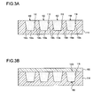
- Fig. 3A is a horizontal cross sectional view showing the schematic structure of the light emitting member and the light emitting member accommodating unit of the automotive lamp according to variation 1.
- the light emitting member accommodating unit 114 of the automotive lamp 1 according to variation 1 is provided with a plurality of recesses 116.
- the light emitting member 150 is accommodated in each of the plurality of recesses 116.
- the light incidence surfaces 150a and the side surfaces 150c of the light emitting member are in contact with the light emitting member accommodating unit 114.
- the variation represents a case in which the light emitting member 150 of the first embodiment is divided into a plurality of segments and respectively accommodated in the recesses 116.
- the variation increases the total area of contact between the light emitting members 150 and the light emitting member accommodating unit 114 and so increases the heat dissipating efficiency of the light emitting member 150. Also, the volume of the light emitting member 150 accommodated in each of the recesses 116 is reduced so that the heat dissipating efficiency of the light emitting member 150 is further improved. Accordingly, degradation in light emitting efficiency of the light emitting member 150 is further mitigated.
- Fig. 3A shows four light emitting members 150, but the number of members is not limited to this.
- a portion of the light emitting member accommodating unit 114 is interposed between the two adjacent light emitting members 150 as a partition wall.
- the partition wall is inherently translucent so that a portion of the white light W emitted by the adjacent two light emitting members 150 is directed toward the projection lens 170 from the lateral end face of the partition wall facing the space in front of the lamp.
- the surfaces of the recesses 116 in contact with the side surfaces 150c may be provided with a reflecting part formed by, for example, depositing metal. In this case, it is possible to make the light emitting members 150 appear as independent light emitting units and realize a light distribution pattern using the edge portions of the light emitting units.
- Fig. 3B is a horizontal cross sectional view showing the schematic structure of the light emitting member and the light emitting member accommodating unit of the automotive lamp according to variation 2.
- the automotive lamp 1 according to variation 2 is further provided with a cover member 180.
- the cover member 180 is translucent and is in contact with the light emission surface 150b of the light emitting member 150 and with the support member 110.
- the cover member 180 is in contact with the light emitting member accommodating unit 114 of the support member 110.
- the cover member 180 may be in contact only with the body 112 or with the light emitting member accommodating unit 114 and the body 112.
- the cover member 180 is translucent and so is capable of transmitting the white light W emitted by the light emitting member 150.
- the cover member 180 is formed of a material having a higher thermal conductivity than air.
- the cover member 180 may be formed of the same material as can be used for the light emitting member accommodating unit 114.
- the cover member 180 does not substantially contain a phosphor.
- the light emitting member accommodating unit 114 has a structure similar to that of variation 1. In other words, a plurality of recesses 116 are provided. Alternatively, the light emitting member accommodating unit 114 may be provided with the same structure as that of the first embodiment, i.e., may be provided with a single recess 116.
- Fig. 4A is a horizontal cross sectional view showing the schematic structure of the light source, the light guiding member, the light emitting member accommodating unit, and the light emitting member in the automotive lamp according to the second embodiment.
- Fig. 4B schematically shows the shapes of the light incidence surface of the light emitting member and the beam pattern of the laser light.
- the automotive lamp 1 is further provided with the light guiding member 190.
- the light guiding member 190 is formed of a linear member such as an optical fiber.
- a light incidence part 192 at one end of the light guiding member 190 is disposed toward the light source 130, and light emission parts 194 at the other end are disposed toward the light emitting member 150.
- the light guiding member 190 is adapted to guide the laser light L incident from the light incidence part 192 to the light emitting member 150 by emitting the light from the light emission parts 194.
- the laser light L radiated from the light source 130 is incident on the light incidence part 192 of the light guiding member 190 via the condensing lens 140.
- the laser light L incident on the light incidence part 192 travels in the light guiding member 190 and reaches the light emission parts 194.
- the laser light L is emitted from the light emission parts 194 and transmitted through the light emitting member accommodating unit 114, before being incident on the light emitting member 150.
- the light emitting member accommodating unit 114 has a structure similar to that of variation 1. In other words, a plurality of recesses 116 are provided. The number of light emission parts 194 provided in the light guiding member 190 is determined by the number of recesses 116. The light emission parts 194 are adapted to irradiate the light emitting members 150 in the respective recesses 116 with the laser light L.
- the light emitting member accommodating unit 114 has a structure similar to that of the first embodiment. In other words, a single recess 116 is provided.
- the cover member 180 may additionally be provided.
- the beam pattern P of the laser light L emitted from the light guiding member 190 and the light incidence surface 150a of the light emitting member are substantially equal in shape or substantially analogous in shape. More specifically, the light incidence surface 150a of the light emitting member and the beam pattern P on the light incidence surface 150a of the light emitting member are substantially equal in shape or substantially analogous in shape. Further, the light incidence surface 150a of the light emitting member has a shape collapsed in one direction as viewed in the direction of a normal to the light incidence surface 150a of the light emitting member.
- the beam pattern P of the laser light L has a shape collapsed on the light incidence surface 150a of the light emitting member in the same direction as the direction in which the light incidence surface 150a of the light emitting member 150 is collapsed.
- the light incidence surface 150a of the light emitting member and the beam pattern P are both substantially rectangular and are analogous to each other such that the light incidence surface 150a of the light emitting member is larger than the beam pattern P.
- the beam pattern P has a light distribution of a top hat shape.
- the laser light L can be incident on the light emitting member 150 efficiently. This improves the external quantum efficiency of the light emitting member 150 and improves the light emitting efficiency of the light emitting member 150.
- the automotive lamp 1 is configured such that the relationship between the shape of the light incidence surface of the light incidence part 192 and the shape of the beam pattern P is similar to the relationship between the shape of the light incidence surface 150a of the light emitting member and the shape of the beam pattern P.
- the light incidence surface of the light incidence part 192 of the light guiding member 190 and the beam pattern P of the laser light L on the light incidence surface of the light incidence part 192 are substantially equal in shape or substantially analogous in shape.
- the description with reference to Fig. 4B applies to the shapes of the light incidence surface of the light incidence part 192 and the beam pattern P, by replacing the light incidence surface 150a of the light emitting member of Fig. 4B with the light incidence surface of the light incidence part 192 of the light guiding member 190. In this way, the laser light L can be incident on the light guiding member 190 efficiently. Accordingly, the light emitting efficiency of the light emitting member 150 can be improved.
- the lamp unit 100 in the above-described embodiments and variations is a lamp unit of projector type.
- the type of the lamp unit 100 is not limited to this and the lamp unit may be of reflective type.
- the light emitting member 150 is described as radiating the white light W but may alternatively radiate light of other colors such as amber colored light.
- the light source 130 may an LED so long as the light emitting member 150 is used.
- the automotive lamp 1 has a transmission type structure in which the laser light L is incident on one of the surfaces of the light emitting member 150 (the light incidence surface 150a of the light emitting member) and the white light W is emitted from the other surface (the light emission surface 150b) opposite to the surface of incidence.
- the type of the automotive lamp 1 is not limited to this.
- the automotive lamp 1 may have a reflection type structure in which the laser light L is incident on one of the surfaces (e.g., the light emission surface 150b) and the white light W is emitted from the surface of incidence.
- the automotive lamp 1 may be a sine lamp or a tail lamp.
- 1 automotive lamp 110 support member, 114 light emitting member accommodating unit, 114b rough surface area, 116 recess, 130 light source, 150 light emitting member, 150a light incidence surface of light emitting member, 150b light emission surface, 150c side surface, 180 cover member, 190 light guiding member, L laser light, P beam pattern
- the present invention is applicable to automotive lamps.
Landscapes
- Engineering & Computer Science (AREA)
- General Engineering & Computer Science (AREA)
- Physics & Mathematics (AREA)
- Optics & Photonics (AREA)
- Microelectronics & Electronic Packaging (AREA)
- Non-Portable Lighting Devices Or Systems Thereof (AREA)
- Arrangement Of Elements, Cooling, Sealing, Or The Like Of Lighting Devices (AREA)
Abstract
Description
- The present invention relates to an automotive lamp and, more particularly, to an automotive lamp used in a vehicle such as a motorcar.
-
Patent document 1 discloses a light emitting device including a laser diode, and a solid phosphor glass excited by the light emitted by the laser diode and emitting light of a color different from the color of the light emitted by the laser diode. The laser diode in this light emitting device is surrounded by a reflector, and the phosphor glass is supported at an open end of the reflector by a translucent member made of, for example, transparent glass. The translucent member is in contact with the side of the phosphor glass and supports the phosphor glass. - [patent document 1] Pamphlet of
WO07/105647 - We have made intensive study on automotive lamps in which a laser light source is used and found out that there is room for improvement in related-art light emitting devices for use as a laser light source in that degradation in light emitting efficiency of a light emitting member such as a phosphor due to generated heat should be mitigated.
- The present invention addresses the issue and a purpose thereof is to provide a technology for mitigating degradation in light emitting efficiency of a light emitting member.
- An embodiment of the present invention relates to an automotive lamp. The automotive lamp includes: a light source; a light emitting member that receives light from the light source and emits light; and a support member that supports the light emitting member. The support member includes a translucent light emitting member accommodating unit. The light emitting member accommodating unit includes a recess in which the light emitting member is accommodated. A light incidence surface and side surfaces of the light emitting member are in contact with the light emitting member accommodating unit in a state in which the light emitting member is accommodated in the recess.
- According to this embodiment, degradation in light emitting efficiency of a light emitting member is mitigated.
- The light emitting member accommodating unit may include a plurality of recesses, and the light emitting member may be accommodated in each of the plurality of recesses. According to this embodiment, degradation in light emitting efficiency of a light emitting member is mitigated more properly. On a surface of the light emitting member accommodating unit that is contact with the light emitting member is provided a rough surface area having a surface roughness greater than that of a light incidence surface of the light emitting member accommodating unit. According to this embodiment, degradation in light emitting efficiency of a light emitting member is mitigated more properly.
- In any of the foregoing embodiments, the light incidence surface of the light emitting member may have a shape collapsed in one direction as viewed in the direction of a normal to the light incidence surface, and the light source may be a laser light source and a beam pattern of laser light radiated from the light source may have a shape collapsed on the light incidence surface of the light emitting member in the same direction as the direction in which the light incidence surface of the light emitting member is collapsed. According to this embodiment, light emitting efficiency of a light emitting member is improved.
- The automotive lamp according to any of the foregoing embodiments may further include a light guiding member that is disposed such that one end is toward the light source and the other end is toward the light emitting member, and guides light to the light emitting member, wherein the light source is a laser light source, and a beam pattern of laser light emitted from the light guiding member and the light incidence surface of the light emitting member are substantially equal in shape or substantially analogous in shape. According to this embodiment, light emitting efficiency of a light emitting member is improved.
- The automotive lamp according to any of the foregoing embodiments may further include a translucent cover member that is in contact with a light emission surface of the light emitting member and with the support member. According to this embodiment, degradation in light emitting efficiency of a light emitting member is mitigated more properly.
- The present invention provides a technology for mitigating degradation in light emitting efficiency of a light emitting member.
-
-
Fig. 1 is a horizontal cross sectional view showing the schematic structure of the automotive lamp according to the first embodiment; -
Fig. 2A is a horizontal cross sectional view showing the schematic structure of the light emitting member and the light emitting member accommodating unit of the automotive lamp according to the first embodiment;Fig. 2B is a cross sectional view along line A-A ofFig. 2A ; -
Fig. 3A is a horizontal cross sectional view showing the schematic structure of the light emitting member and the light emitting member accommodating unit of the automotive lamp according tovariation 1;Fig. 3B is a horizontal cross sectional view showing the schematic structure of the light emitting member and the light emitting member accommodating unit of the automotive lamp according to variation 2; -
Fig. 4A is a horizontal cross sectional view showing the schematic structure of the light source, the light guiding member, the light emitting member accommodating unit, and the light emitting member in the automotive lamp according to the second embodiment; and -
Fig. 4B schematically shows the shapes of the light incidence surface of the light emitting member and the beam pattern of the laser light. - A description will be given of an embodiment of the present invention with reference to the drawings. Like numerals represent like elements so that the description will be omitted accordingly. The embodiments of the present invention are not limited to those described above and appropriate combinations or replacements of the features of the embodiments are also encompassed by the present invention.
-
Fig. 1 is a horizontal cross sectional view showing the schematic structure of the automotive lamp according to the first embodiment. Anautomotive lamp 1 according to the embodiment is an automotive head lamp apparatus provided with, for example, a pair of head lamp units disposed on the left and right of the front of a vehicle. The pair of head lamp units have substantially the same structure so thatFig. 1 shows the structure of only one of the left and right units to represent theautomotive lamp 1. Theautomotive lamp 1 is provided with a lamp body 2 that opens to a space in front of the vehicle and a translucent cover 4 fitted to cover the opening of the lamp body 2. The translucent cover 4 is formed of translucent resin or glass. Alamp unit 100 is accommodated in a lamp chamber 3 formed by the lamp body 2 and the translucent cover 4. - The
lamp unit 100 is of so-called projection type and is provided with asupport member 110, alight source mount 120, alight source 130, acondensing lens 140, alight emitting member 150, alens holder 160, and aprojection lens 170. - The
support member 110 is a member for supporting thelight emitting member 150. Thesupport member 110 is a substantially plate-shaped member formed of a metal material such as aluminum. The two main surfaces of thesupport member 110 are disposed to face the space in front of and behind the lamp. Thesupport member 110 includes an opening 113 at the center that extends through thesupport member 110 in the front-back direction of the lamp. Thelight emitting member 150 is disposed in the opening 113. Thelight source 130 and thecondensing lens 140 are fixed, via thelight source mount 120, on the main surface of thesupport member 110 facing the space behind the lamp. Theprojection lens 170 is fixed, via thelens holder 160, on the main surface of thesupport member 110 facing the space in front of the lamp. Therefore, thesupport member 110 also functions as a member for supporting thelight source 130, thecondensing lens 140, and theprojection lens 170. - The
support member 110 is provided with thread holes at predetermined positions in the circumferential edge. Aiming screws 6 extending forward through the lamp body 2 are threadably engaged with the thread holes. In this way, thesupport member 110 is mounted in the lamp body 2. Theautomotive lamp 1 is configured such that a light axis O of thelamp unit 100 can be adjusted horizontally or vertically by using the aiming screws 6. - The
light source mount 120 is a member having a shape of a bottomed cylinder formed of a metal material such as aluminum. The open end of thelight source mount 120 is fixed by, for example, welding to the main surface of thesupport member 110 facing the space behind the lamp. Thelight source 130 fixed to the inner surface of the bottom of thelight source mount 120 and a plurality ofheat dissipating fins 102 are fixed to the outer surface of the bottom. The heat generated by thelight source 130 is dissipated via thelight source mount 120 and theheat dissipating fins 102. - The
light source 130 is a laser light source formed by a laser diode (semiconductor laser) emitting laser light L. The structure of the laser diode forming thelight source 130 is publicly known so that a detailed description thereof is omitted. Thelight source 130 is fixed to the inner surface of the bottom of thelight source mount 120 such that the light emission surface faces the space in front of the lamp. The condensinglens 140 condenses the laser light L emitted by thelight source 130. The condensinglens 140 is disposed between thelight source 130 and thelight emitting member 150 and is fixed to thelight source mount 120. The laser light L emitted by thelight source 130 is condensed by the condensinglens 140 and is incident on thelight emitting member 150. Instead of the condensinglens 140, thelamp unit 100 may alternatively be provided with a collimating lens for transforming the laser light L emitted by thelight source 130 into parallel light. - The
light emitting member 150 is a member that receives the light from the light source and emits light. In this embodiment, thelight emitting member 150 is formed by a phosphor configured to receive the laser light L from thelight source 130 and emits light having a wavelength different from the laser light L (e.g., light having a longer wavelength than the laser light L). Thelight emitting member 150 includes alight incidence surface 150a on which the laser light L is incident and alight emission surface 150b from which the light generated inside thelight emitting member 150 is emitted. Thelight emission surface 150b represents the light emission surface of thelight emitting member 150. - The
automotive lamp 1 according to the embodiment is configured to excite thelight emitting member 150 by irradiating thelight emitting member 150 with the laser light L and radiate non-coherent light generated as a result. Exemplary combinations of thelight source 130 and thelight emitting member 150 are described below. - In one combination, the
light source 130 is implemented by a laser diode for radiating blue laser light and thelight emitting member 150 is implemented by a member containing a phosphor adapted to subject the blue laser light to wavelength conversion to produce yellow light. For example, thelight emitting member 150 is formed of a resin that contains a yellow light emitting phosphor and is translucent. Thelight emitting member 150 may be a phosphorescent ceramic produced by sintering a transparent ceramic base containing a phosphor material, or a glass containing a phosphor material. In this combination, when the blue laser light emitted by thelight source 130 is incident on thelight emitting member 150 via thelight incidence surface 150a of thelight emitting member 150, a portion of the light is subject to wavelength conversion by thelight emitting member 150 and turned into yellow light before being emitted from thelight emission surface 150b. Thelight emitting member 150 generates heat as the laser light L is subject to wavelength conversion. The remaining portion of the blue laser light is transmitted through thelight emitting member 150 and emitted from thelight emission surface 150b. The yellow light generated in thelight emitting member 150 and the blue laser light transmitted through thelight emitting member 150 are mixed and turned into white light W, which travels toward theprojection lens 170. - In another combination, the
light source 130 is implemented by a laser diode for radiating ultraviolet laser light and thelight emitting member 150 is implemented by a member containing a blue light emitting phosphor adapted to subject the ultraviolet light to wavelength conversion to produce blue light and a yellow light emitting phosphor adapted to subject the ultraviolet light to wavelength conversion to produce yellow light. In this combination, the ultraviolet light emitted by thelight source 130 is subject to wavelength conversion by thelight emitting member 150 to produce blue light and yellow light. The blue light and the yellow light are subject to additive color mixing and turned into white light W before being emitted by thelight incidence surface 150b. Alternatively, the blue light and the yellow light generated are emitted from thelight emitting member 150 and subject to additive color mixing. The resultant white light W travels toward theprojection lens 170. - The
light emitting member 150 is supported by thesupport member 110 and is disposed between the condensinglens 140 and theprojection lens 170. Thesupport member 110 includes a substantially plate-shapedbody 112 formed of a metal material such as aluminum and a translucent and substantially plate-shaped light emittingmember accommodating unit 114. Thebody 112 includes anopening 113 at the center and thread holes at the circumferential edge. The aiming screws 6 are engaged with the thread holes. A plurality ofheat dissipating fins 102 are fixed to the main surface of thebody 112 facing the space behind the lamp. - The light emitting
member accommodating unit 114 is fitted in theopening 113 and is disposed between the condensinglens 140 and theprojection lens 170. The light emittingmember accommodating unit 114 includes arecess 116 on the main surface thereof facing the space in front of the lamp to accommodate thelight emitting member 150. Thesupport member 110 supports thelight emitting member 150 by accommodating thelight emitting member 150 in therecess 116. The main surface of the light emittingmember accommodating unit 114 facing the space behind the lamp is configured as alight incidence surface 114a of the light emitting member accommodating unit on which the laser light L is incident. The light emittingmember accommodating unit 114 is translucent and so can transmit the laser light L. Further, the light emittingmember accommodating unit 114 does not substantially include a phosphor. - The light emitting
member accommodating unit 114 is translucent and is formed of a material having a higher thermal conductivity than air (thermal conductivity: about 0.02 W/m·k). Examples of the material forming the light emittingmember accommodating unit 114 include polycrystalline alumina (Al2O3, thermal conductivity: 20-30 W/m·k), sapphire (monocrystal Al2O3, thermal conductivity: 20-30 W/m·k), yttria (Y2O3, thermal conductivity: 20-30 W/m·k), YAG (Y3Al5O32, thermal conductivity: 5-15 W/m·k), glass (thermal conductivity: about 1 W/m·k), etc. To meet the need for translucency, rigidity, thermal conductivity, availability, cost, etc., polycrystalline alumina is preferable as a material for forming the light emittingmember accommodating unit 114. It is preferable that the average grain diameter of the crystal grain of polycrystalline alumina be 50-70 µm. By configuring the average grain diameter to be 50 µm or larger, the light emittingmember accommodating unit 114 can be more translucent. By configuring the average grain diameter to be 70 µm or less, the light emittingmember accommodating unit 114 can be more rigid. - The
lens holder 160 is a cylindrical member formed of a metal material such as aluminum. One of the open ends thereof is fixed by, for example, welding to the main surface of thesupport member 110 facing the space in front of the lamp. Theprojection lens 170 is fixed to the open end of thelens holder 160 facing the space in front of the lamp. Theprojection lens 170 is comprised of a plano-convex aspherical lens in which the front surface is convex and the back surface is planar. Theprojection lens 170 projects a light source image formed on the back focal plane including the back focal point of theprojection lens 170 onto a virtual vertical screen in front of the lamp as an inverted image. Theprojection lens 170 is disposed such that the back focal point is located on the light axis O of thelamp unit 100 and in the vicinity of thelight emission surface 150b of thelight emitting member 150. - The laser light L radiated by the
light source 130 is incident on the light emittingmember accommodating unit 114 via the condensinglens 140 and thelight incidence surface 114a of the light emitting member accommodating unit. The laser light L incident on the light emittingmember accommodating unit 114 travels in the light emittingmember accommodating unit 114 and is incident on thelight emitting member 150 via thelight incidence surface 150a of the light emitting member. The laser light L incident on thelight emitting member 150 is subject to wavelength conversion in thelight emitting member 150. The white light W produced as a result is emitted from thelight emission surface 150b of thelight emitting member 150, is incident on theprojection lens 170, and is projected by theprojection lens 170 in front of the lamp as substantially parallel light. - A detailed description will be given of the structure to support the
light emitting member 150 and the heat dissipating mechanism.Fig. 2A is a horizontal cross sectional view showing the schematic structure of the light emitting member and the light emitting member accommodating unit of the automotive lamp according to the first embodiment. As shown inFig. 2A , thelight incidence surface 150a and side surfaces 150c of thelight emitting member 150 are in contact with the light emittingmember accommodating unit 114 in a state in which thelight emitting member 150 is accommodated in therecess 116. Therefore, most of the heat generated as the laser light L is subject to wavelength conversion in thelight emitting member 150 is dissipated in part to the light emittingmember accommodating unit 114 via the side surfaces 150c as indicated by arrow h1 and is also dissipated in part to the light emittingmember accommodating unit 114 via thelight incidence surface 150a of the light emitting member as indicated by arrow h2. The heat dissipated to the light emittingmember accommodating unit 114 is conducted to thebody 112 and theheat dissipating fins 102 and dissipated to the atmosphere. - On the surface of the light emitting
member accommodating unit 114 that is contact with thelight emitting member 150 is provided arough surface area 114b having a surface roughness greater than that of thelight incidence surface 114a of the light emitting member accommodating unit. Of the surfaces of the light emittingmember accommodating unit 114 according to this embodiment, therough surface area 114b is provided on the surface in contact with the side surfaces 150c of thelight emitting member 150. Therough surface area 114b includes micro-asperities and is formed by roughing the surface of the light emittingmember accommodating unit 114 by, for example, etching. It is preferable that therough surface area 114b be formed on the side of therecess 116 rather than on the bottom thereof in order not to block incidence of the laser light L on thelight emitting member 150. Therough surface area 114b may be provided on the bottom of therecess 116. For example, by providing therough surface area 114b on the bottom of therecess 116 as well as on the side thereof, the heat dissipating efficiency of thelight emitting member 150 is improved. - A description will now be given of the relationship between the shape of the
light incidence surface 150a of the light emitting member and the beam pattern of the laser light L radiated by thelight source 130.Fig. 2B is a cross sectional view along line A-A ofFig. 2A. Fig. 2B shows thelight incidence surface 150a of the light emitting member as viewed in the direction of a normal to thelight incidence surface 150a of the light emitting member. As shown inFig. 2B , thelight incidence surface 150a of the light emitting member has a shape collapsed in one direction as viewed in the direction of a normal to thelight incidence surface 150a of the light emitting member. Further, the beam pattern P of the laser light L radiated from thelight source 130 has a shape collapsed on thelight incidence surface 150a of the light emitting member in the same direction as the direction in which thelight incidence surface 150a of the light emitting member is collapsed. - For example, the
light incidence surface 150a of the light emitting member and the beam pattern P of the laser light L have a shape having a longer side and a shorter side, or a longer diameter and a shorter diameter (e.g., rectangle, ellipse, oblong shape) . On thelight incidence surface 150a of the light emitting member, the longer side or the longer diameter of thelight incidence surface 150a of the light emitting member, and the longer side or the longer diameter of the beam pattern P are aligned in a direction defined around the normal Z of thelight incidence surface 150a of the light emitting member (the direction indicated by arrow m in the figure). In other words, the orientation of thelight emitting member 150 with respect to thelight source 130 is defined such that the longer side or the longer diameter of thelight incidence surface 150a of the light emitting member and the longer side or the longer diameter of the beam pattern P are parallel. In this embodiment, thelight incidence surface 150a of the light emitting member is substantially rectangular and the beam pattern P is substantially elliptical or substantially oblong. A longer side 150aL of thelight incidence surface 150a of the light emitting member and a longer diameter PL of the beam pattern P are parallel to each other. Stated otherwise, thelight incidence surface 150a of the light emitting member and the beam pattern P of the laser light L on thelight incidence surface 150a of the light emitting member are substantially equal in shape or substantially analogous in shape. - As described above, the
support member 110 of theautomotive lamp 1 according to the embodiment includes the light emittingmember accommodating unit 114 having therecess 116. Thelight emitting member 150 is accommodated in therecess 116 and thelight incidence surface 150a and the side surfaces 150c of the light emitting member are in contact with the light emittingmember accommodating unit 114. In this embodiment, thelight incidence surface 150a and the fourside surfaces 150c of the light emitting member are in contact with the light emittingmember accommodating unit 114. This allows the heat generated in thelight emitting member 150 to be conducted to the light emittingmember accommodating unit 114 having a high thermal conductivity via thelight incidence surface 150a of the light emitting member as well as via the side surfaces 150c of thelight emitting member 150. Therefore, the heat dissipating performance of thelight emitting member 150 is increased as compared with a structure in which the heat is dissipated to the support member only via the side surfaces of the light emitting member. This mitigates degradation in light emitting efficiency (conversion efficiency of laser light) of thelight emitting member 150 that occurs due to generated heat. Consequently, the luminance of thelight emitting member 150 can be increased and the light irradiation performance of theautomotive lamp 1 is improved. In the case that silicone resin is used for the binder member of the phosphor, the thermal conductivity of thelight emitting member 150 is about 0.2 W/m·k. - For the purpose of increasing the luminance of the
light emitting member 150, it is useful to decrease the area on thelight incidence surface 150a of the light emitting member irradiated by the laser light L. In this case, a small area will be irradiated by high-energy light with the result that the temperature of thelight emitting member 150 is likely to increase. This is addressed by the embodiment by increasing the heat dissipating efficiency of thelight emitting member 150. It is therefore easy to realize a design for increasing the luminance of thelight emitting member 150. - Further, since the
recess 116 holds thelight emitting member 150 in place, the likelihood of dislocation of thelight emitting member 150 from thesupport member 110 is reduced. It also makes it possible to attempt to restrain an increase in the number of components to build theautomotive lamp 1 and the number of steps for assembly. - For example, the
light emitting member 150 is formed as described below. In other words, a phosphor is first mixed with a liquid or gelatinous binder member to produce a phosphor paste. The phosphor paste is then poured into the opening of the support member. The binder member in the phosphor paste is cured by, for example, calcination. Thelight emitting member 150 is formed through the steps described above. Alternatively, the preformedlight emitting member 150 is set in the opening. For example, silicone resin, fluorine resin, etc. is used for the binder member. - The
automotive lamp 1 according to the embodiment is configured such that thelight emitting member 150 is accommodated in therecess 116 of the light emittingmember accommodating unit 114. Therefore, thelight emitting member 150 may be formed by using therecess 116 as a mold form (guide) for the phosphor paste, pouring the phosphor paste into therecess 116, and calcinating the phosphor paste within therecess 116. Therefore, thelight emitting member 150 can be manufactured easily and the steps of manufacturing theautomotive lamp 1 is simplified. Since therecess 116 is used as a mold form, the edge portions of thelight emitting member 150 can be formed accurately. Accordingly, accuracy of dimension of thelight emitting member 150 can be increased. Further, the shape of thelight emitting member 150 can be maintained stably. It should be particularly noted that the thickness of thelight emitting member 150 is normally about 0.7 mm, which is very thin. It is therefore difficult to achieve precision in thickness. By forming thelight emitting member 150 by filling therecess 116 with the phosphor paste, thelight emitting member 150 can be formed with a highly accurately defined thickness. Moreover, the thickness of thelight emitting member 150 can be easily changed by changing the depth of therecess 116. The shapes of thelight incidence surface 150a and thelight emission surface 150b of the light emitting member can be easily changed by changing the shape of therecess 116. - The surface of the light emitting
member accommodating unit 114 that is contact with thelight emitting member 150 is provided with therough surface area 114b having a surface roughness greater than that of thelight incidence surface 114a of the light emitting member accommodating unit. This increases the area of contact between thelight emitting member 150 and the light emittingmember accommodating unit 114 and so can increase the heat dissipating efficiency of thelight emitting member 150 and mitigate degradation in light emitting efficiency of thelight emitting member 150. Also, the likelihood of dislocation of thelight emitting member 150 from thesupport member 110 is reduced. The surface of the light emittingmember accommodating unit 114 that is in contact with thelight emitting member 150 may be provided with a reflecting film in place of or in addition to therough surface area 114b. This increases the luminance of thelight emitting member 150. The reflecting film may be exemplified by a film adapted to reflect light in the entire range of visible light wavelength, or a film adapted to transmit light having a wavelength found in a portion of the visible light wavelength range and reflect light having a wavelength found in the remainder of the visible light wavelength range. The reflecting film adapted to transmit light having a wavelength found in a portion of the visible light wavelength is exemplified by a film adapted to transmit light having a wavelength in a region of blue light (380-480 nm) and reflect light having a wavelength in green, yellow, and red regions (480-780 nm). - In a lamp structure in which the
light emitting member 150 is excited by the laser light L to radiate noncoherent light generated as a result, improvement in utilization ratio of the laser light L is a challenge. This is addressed by the embodiment by configuring thelight emitting member 150 to be collapsed in one direction as viewed in the direction of a normal to thelight incidence surface 150a of the light emitting member. Further, the beam pattern P of the laser light L radiated from thelight source 130 has a shape collapsed on thelight incidence surface 150a of the light emitting member in the same direction as the direction in which thelight emitting member 150 is collapsed. By synchronizing the shapes of thelight incidence surface 150a of the light emitting member and of the beam pattern P in a direction defined around the light axis of the light source 130 (the direction indicated by arrow m in the figure), the laser light L can be incident on thelight emitting member 150 efficiently. This improves the external quantum efficiency of thelight emitting member 150 and improves the light emitting efficiency of thelight emitting member 150. Thelight emission surface 150b of thelight emitting member 150 according to the embodiment is rectangular. Since a light distribution pattern can be formed by using the rectangular light emitting member, light distribution control is simplified. - The following variations to the
automotive lamp 1 according to the embodiment are possible. - The structure of the
automotive lamp 1 according tovariation 1 is similar to that of theautomotive lamp 1 according to the first embodiment except that a plurality ofrecesses 116 are provided. The features that are identical to those of the first embodiment are denoted by the same numerals and a description or illustration thereof is omitted.Fig. 3A is a horizontal cross sectional view showing the schematic structure of the light emitting member and the light emitting member accommodating unit of the automotive lamp according tovariation 1. - The light emitting
member accommodating unit 114 of theautomotive lamp 1 according tovariation 1 is provided with a plurality ofrecesses 116. Thelight emitting member 150 is accommodated in each of the plurality ofrecesses 116. In a state in which thelight emitting members 150 are accommodated in therecesses 116, thelight incidence surfaces 150a and the side surfaces 150c of the light emitting member are in contact with the light emittingmember accommodating unit 114. In other words, given that the total volume of thelight emitting members 150 is equal to the volume of thelight emitting member 150 of the first embodiment, the variation represents a case in which thelight emitting member 150 of the first embodiment is divided into a plurality of segments and respectively accommodated in therecesses 116. - Thus, the variation increases the total area of contact between the
light emitting members 150 and the light emittingmember accommodating unit 114 and so increases the heat dissipating efficiency of thelight emitting member 150. Also, the volume of thelight emitting member 150 accommodated in each of therecesses 116 is reduced so that the heat dissipating efficiency of thelight emitting member 150 is further improved. Accordingly, degradation in light emitting efficiency of thelight emitting member 150 is further mitigated.Fig. 3A shows four light emittingmembers 150, but the number of members is not limited to this. - A portion of the light emitting
member accommodating unit 114 is interposed between the two adjacentlight emitting members 150 as a partition wall. The partition wall is inherently translucent so that a portion of the white light W emitted by the adjacent two light emittingmembers 150 is directed toward theprojection lens 170 from the lateral end face of the partition wall facing the space in front of the lamp. This make the plurality of light emittingmembers 150 appear as one light emitting unit. The surfaces of therecesses 116 in contact with the side surfaces 150c may be provided with a reflecting part formed by, for example, depositing metal. In this case, it is possible to make thelight emitting members 150 appear as independent light emitting units and realize a light distribution pattern using the edge portions of the light emitting units. - The structure of the
automotive lamp 1 according to variation 2 is similar to that of theautomotive lamp 1 according to the first embodiment except that acover member 180 is provided. The features that are identical to those of the first embodiment are denoted by the same numerals and a description or illustration thereof is omitted.Fig. 3B is a horizontal cross sectional view showing the schematic structure of the light emitting member and the light emitting member accommodating unit of the automotive lamp according to variation 2. - The
automotive lamp 1 according to variation 2 is further provided with acover member 180. Thecover member 180 is translucent and is in contact with thelight emission surface 150b of thelight emitting member 150 and with thesupport member 110. In this variation, thecover member 180 is in contact with the light emittingmember accommodating unit 114 of thesupport member 110. Thecover member 180 may be in contact only with thebody 112 or with the light emittingmember accommodating unit 114 and thebody 112. Thecover member 180 is translucent and so is capable of transmitting the white light W emitted by thelight emitting member 150. As well as being translucent, thecover member 180 is formed of a material having a higher thermal conductivity than air. Thecover member 180 may be formed of the same material as can be used for the light emittingmember accommodating unit 114. Thecover member 180 does not substantially contain a phosphor. - Thus, by allowing the
light emission surface 150b of thelight emitting member 150 to be in contact with thecover member 180, the heat generated in thelight emitting member 150 can be conducted from thelight emission surface 150b to supportmember 110 via thecover member 180. This can increase the heat dissipating efficiency of thelight emitting member 150 and mitigate degradation in the light emitting efficiency of thelight emitting member 150 more properly. The light emittingmember accommodating unit 114 according to this variation has a structure similar to that ofvariation 1. In other words, a plurality ofrecesses 116 are provided. Alternatively, the light emittingmember accommodating unit 114 may be provided with the same structure as that of the first embodiment, i.e., may be provided with asingle recess 116. - The structure of the
automotive lamp 1 according to the second embodiment is similar to that of theautomotive lamp 1 according to the first embodiment except that alight guiding member 190 is provided. The features that are identical to those of the first embodiment are denoted by the same numerals and a description or illustration thereof is omitted.Fig. 4A is a horizontal cross sectional view showing the schematic structure of the light source, the light guiding member, the light emitting member accommodating unit, and the light emitting member in the automotive lamp according to the second embodiment.Fig. 4B schematically shows the shapes of the light incidence surface of the light emitting member and the beam pattern of the laser light. - The
automotive lamp 1 according to this embodiment is further provided with thelight guiding member 190. Thelight guiding member 190 is formed of a linear member such as an optical fiber. Alight incidence part 192 at one end of thelight guiding member 190 is disposed toward thelight source 130, andlight emission parts 194 at the other end are disposed toward thelight emitting member 150. Thelight guiding member 190 is adapted to guide the laser light L incident from thelight incidence part 192 to thelight emitting member 150 by emitting the light from thelight emission parts 194. In other words, the laser light L radiated from thelight source 130 is incident on thelight incidence part 192 of thelight guiding member 190 via the condensinglens 140. The laser light L incident on thelight incidence part 192 travels in thelight guiding member 190 and reaches thelight emission parts 194. The laser light L is emitted from thelight emission parts 194 and transmitted through the light emittingmember accommodating unit 114, before being incident on thelight emitting member 150. - The light emitting
member accommodating unit 114 according to this embodiment has a structure similar to that ofvariation 1. In other words, a plurality ofrecesses 116 are provided. The number oflight emission parts 194 provided in thelight guiding member 190 is determined by the number ofrecesses 116. Thelight emission parts 194 are adapted to irradiate thelight emitting members 150 in therespective recesses 116 with the laser light L. The light emittingmember accommodating unit 114 has a structure similar to that of the first embodiment. In other words, asingle recess 116 is provided. Thecover member 180 may additionally be provided. By providing thelight guiding member 190 as described above, the flexibility of arrangement of thelight source 130 and thelight emitting member 150 can be improved. - As shown in
Fig. 4B , the beam pattern P of the laser light L emitted from thelight guiding member 190 and thelight incidence surface 150a of the light emitting member are substantially equal in shape or substantially analogous in shape. More specifically, thelight incidence surface 150a of the light emitting member and the beam pattern P on thelight incidence surface 150a of the light emitting member are substantially equal in shape or substantially analogous in shape. Further, thelight incidence surface 150a of the light emitting member has a shape collapsed in one direction as viewed in the direction of a normal to thelight incidence surface 150a of the light emitting member. The beam pattern P of the laser light L has a shape collapsed on thelight incidence surface 150a of the light emitting member in the same direction as the direction in which thelight incidence surface 150a of thelight emitting member 150 is collapsed. In this variation, thelight incidence surface 150a of the light emitting member and the beam pattern P are both substantially rectangular and are analogous to each other such that thelight incidence surface 150a of the light emitting member is larger than the beam pattern P. The beam pattern P has a light distribution of a top hat shape. - By configuring the beam pattern P and the
light incidence surface 150a of the light emitting member to be substantially equal in shape or substantially analogous in shape, the laser light L can be incident on thelight emitting member 150 efficiently. This improves the external quantum efficiency of thelight emitting member 150 and improves the light emitting efficiency of thelight emitting member 150. - Further, the
automotive lamp 1 according to this variation is configured such that the relationship between the shape of the light incidence surface of thelight incidence part 192 and the shape of the beam pattern P is similar to the relationship between the shape of thelight incidence surface 150a of the light emitting member and the shape of the beam pattern P. In other words, the light incidence surface of thelight incidence part 192 of thelight guiding member 190 and the beam pattern P of the laser light L on the light incidence surface of thelight incidence part 192 are substantially equal in shape or substantially analogous in shape. The description with reference toFig. 4B applies to the shapes of the light incidence surface of thelight incidence part 192 and the beam pattern P, by replacing thelight incidence surface 150a of the light emitting member ofFig. 4B with the light incidence surface of thelight incidence part 192 of thelight guiding member 190. In this way, the laser light L can be incident on thelight guiding member 190 efficiently. Accordingly, the light emitting efficiency of thelight emitting member 150 can be improved. - The embodiments of the present invention are not limited to those described above and the embodiments and variations may be combined, or various further modifications such as design changes may be made based on the knowledge of a skilled person. The embodiments and variations resulting from such combinations or further modification are also within the scope of the present invention. New embodiments created by combinations of the above-described embodiments and variations and by combinations of the following variations with the above-described embodiments and variations provide combined advantages from the embodiments, variations, and further modifications.
- The
lamp unit 100 in the above-described embodiments and variations is a lamp unit of projector type. The type of thelamp unit 100 is not limited to this and the lamp unit may be of reflective type. Thelight emitting member 150 is described as radiating the white light W but may alternatively radiate light of other colors such as amber colored light. Thelight source 130 may an LED so long as thelight emitting member 150 is used. Theautomotive lamp 1 has a transmission type structure in which the laser light L is incident on one of the surfaces of the light emitting member 150 (thelight incidence surface 150a of the light emitting member) and the white light W is emitted from the other surface (thelight emission surface 150b) opposite to the surface of incidence. However, the type of theautomotive lamp 1 is not limited to this. For example, theautomotive lamp 1 may have a reflection type structure in which the laser light L is incident on one of the surfaces (e.g., thelight emission surface 150b) and the white light W is emitted from the surface of incidence. Theautomotive lamp 1 may be a sine lamp or a tail lamp. - 1 automotive lamp, 110 support member, 114 light emitting member accommodating unit, 114b rough surface area, 116 recess, 130 light source, 150 light emitting member, 150a light incidence surface of light emitting member, 150b light emission surface, 150c side surface, 180 cover member, 190 light guiding member, L laser light, P beam pattern
- The present invention is applicable to automotive lamps.
Claims (6)
- An automotive lamp comprising:a light source;a light emitting member that receives light from the light source and emits light; anda support member that supports the light emitting member, whereinthe support member includes a translucent light emitting member accommodating unit,the light emitting member accommodating unit includes a recess in which the light emitting member is accommodated, anda light incidence surface and side surfaces of the light emitting member are in contact with the light emitting member accommodating unit in a state in which the light emitting member is accommodated in the recess.
- The automotive lamp according to claim 1, wherein
the light emitting member accommodating unit includes a plurality of recesses, and
the light emitting member is accommodated in each of the plurality of recesses. - The automotive lamp according to claim 1 or 2, wherein
on a surface of the light emitting member accommodating unit that is contact with the light emitting member is provided a rough surface area having a surface roughness greater than that of a light incidence surface of the light emitting member accommodating unit. - The automotive lamp according to any one of claims 1 through 3, wherein
the light incidence surface of the light emitting member has a shape collapsed in one direction as viewed in the direction of a normal to the light incidence surface, and
the light source is a laser light source and a beam pattern of laser light radiated from the light source has a shape collapsed on the light incidence surface of the light emitting member in the same direction as the direction in which the light incidence surface of the light emitting member is collapsed. - The automotive lamp according to any one of claims 1 through 4, further comprising:a light guiding member that is disposed such that one end is toward the light source and the other end is toward the light emitting member, and guides light to the light emitting member, whereinthe light source is a laser light source, anda beam pattern of laser light emitted from the light guiding member and the light incidence surface of the light emitting member are substantially equal in shape or substantially analogous in shape.
- The automotive lamp according to any one of claims 1 through 5, further comprising:a translucent cover member that is in contact with a light emission surface of the light emitting member and with the support member.
Applications Claiming Priority (2)
| Application Number | Priority Date | Filing Date | Title |
|---|---|---|---|
| JP2013029239 | 2013-02-18 | ||
| PCT/JP2014/000545 WO2014125782A1 (en) | 2013-02-18 | 2014-02-03 | Vehicle light fitting |
Publications (3)
| Publication Number | Publication Date |
|---|---|
| EP2957818A1 true EP2957818A1 (en) | 2015-12-23 |
| EP2957818A4 EP2957818A4 (en) | 2016-11-23 |
| EP2957818B1 EP2957818B1 (en) | 2020-01-01 |
Family
ID=51353798
Family Applications (1)
| Application Number | Title | Priority Date | Filing Date |
|---|---|---|---|
| EP14751006.9A Active EP2957818B1 (en) | 2013-02-18 | 2014-02-03 | Vehicle light fitting |
Country Status (6)
| Country | Link |
|---|---|
| US (1) | US10247381B2 (en) |
| EP (1) | EP2957818B1 (en) |
| JP (1) | JPWO2014125782A1 (en) |
| KR (1) | KR101763503B1 (en) |
| CN (1) | CN104995453B (en) |
| WO (1) | WO2014125782A1 (en) |
Cited By (3)
| Publication number | Priority date | Publication date | Assignee | Title |
|---|---|---|---|---|
| EP2998789A1 (en) * | 2014-09-04 | 2016-03-23 | Koito Manufacturing Co., Ltd. | Vehicle lamp device and abnormality detector of light source thereof |
| FR3047791A1 (en) * | 2016-02-16 | 2017-08-18 | Valeo Vision | MOTOR VEHICLE PROJECTOR LIGHTING MODULE AND PROJECTOR |
| CN110005997A (en) * | 2017-12-29 | 2019-07-12 | Lg电子株式会社 | Use the car light and its control method of light emitting semiconductor device |
Families Citing this family (12)
| Publication number | Priority date | Publication date | Assignee | Title |
|---|---|---|---|---|
| TWI513938B (en) * | 2014-10-01 | 2015-12-21 | 錼創科技股份有限公司 | Optical module |
| JP2017069110A (en) * | 2015-09-30 | 2017-04-06 | パナソニックIpマネジメント株式会社 | Lighting device |
| JP6593189B2 (en) * | 2016-01-21 | 2019-10-23 | 日亜化学工業株式会社 | Light source device |
| JP6821655B2 (en) | 2016-03-18 | 2021-01-27 | 株式会社小糸製作所 | Fluorescent member and light emitting module |
| KR102525592B1 (en) * | 2016-04-25 | 2023-05-03 | 엘지이노텍 주식회사 | Lighting apparatus |
| US10760766B2 (en) * | 2016-06-30 | 2020-09-01 | Ushio Denki Kabushiki Kaisha | Floodlight device with two optical systems that condense and collimate laser light |
| KR101836845B1 (en) | 2016-07-04 | 2018-03-09 | 엘지전자 주식회사 | Lighting device for vehicle |
| CN106080373A (en) * | 2016-08-16 | 2016-11-09 | 华晨汽车集团控股有限公司 | A kind of drag reduction laser position lamp |
| CN106183968A (en) * | 2016-08-17 | 2016-12-07 | 华晨汽车集团控股有限公司 | A kind of laser position lamp |
| JP6776765B2 (en) * | 2016-09-26 | 2020-10-28 | 日亜化学工業株式会社 | Light emitting device |
| JP7295890B2 (en) * | 2019-01-31 | 2023-06-21 | 京セラ株式会社 | OPTICAL COMPONENT, IMAGE DISPLAY DEVICE AND HEAD-UP DISPLAY USING THE SAME |
| US12601460B2 (en) | 2023-10-27 | 2026-04-14 | Flex-N-Gate Advanced Product Development, Llc | Indirect lighting system and method of use |
Family Cites Families (19)
| Publication number | Priority date | Publication date | Assignee | Title |
|---|---|---|---|---|
| JP4379474B2 (en) * | 2004-10-01 | 2009-12-09 | 日亜化学工業株式会社 | Light emitting device |
| JP5124978B2 (en) | 2005-06-13 | 2013-01-23 | 日亜化学工業株式会社 | Light emitting device |
| EP3264542B1 (en) | 2006-03-10 | 2019-06-05 | Nichia Corporation | Light-emitting device |
| WO2009115976A1 (en) * | 2008-03-20 | 2009-09-24 | Koninklijke Philips Electronics N.V. | Illumination system comprising a luminescent element with a heat sink |
| JP4991834B2 (en) * | 2009-12-17 | 2012-08-01 | シャープ株式会社 | Vehicle headlamp |
| JP5577138B2 (en) * | 2010-04-08 | 2014-08-20 | スタンレー電気株式会社 | Vehicle headlamp |
| JP5533203B2 (en) * | 2010-04-30 | 2014-06-25 | 日亜化学工業株式会社 | Light emitting device and method for manufacturing light emitting device |
| JP5781838B2 (en) * | 2010-08-25 | 2015-09-24 | スタンレー電気株式会社 | Light source device and lamp for vehicle |
| US8708537B2 (en) * | 2010-08-31 | 2014-04-29 | Sharp Kabushiki Kaisha | Lighting apparatus, headlamp, and mobile body |
| JP5314093B2 (en) * | 2010-08-31 | 2013-10-16 | シャープ株式会社 | Lighting device, headlamp, and moving object |
| JP5598974B2 (en) * | 2010-09-01 | 2014-10-01 | シャープ株式会社 | Lighting device |
| US9346395B2 (en) | 2011-03-08 | 2016-05-24 | Sharp Kabushiki Kaisha | Light-emitting apparatus, illumination system, vehicle headlamp, projector, and method for manufacturing light-emitting apparatus |
| JP5703531B2 (en) * | 2011-03-23 | 2015-04-22 | スタンレー電気株式会社 | Vehicle lighting |
| JP2012221634A (en) * | 2011-04-05 | 2012-11-12 | Sharp Corp | Lighting system and headlamp |
| JP5369201B2 (en) * | 2011-04-28 | 2013-12-18 | シャープ株式会社 | Floodlight unit and floodlight device |
| JP2012252838A (en) * | 2011-06-01 | 2012-12-20 | Stanley Electric Co Ltd | Vehicular lamp unit |
| JP6012936B2 (en) * | 2011-06-13 | 2016-10-25 | オリンパス株式会社 | Lighting device |
| JP2013030380A (en) | 2011-07-29 | 2013-02-07 | Sharp Corp | Light-emitting device |
| US20130208496A1 (en) * | 2012-01-31 | 2013-08-15 | Sharp Kabushiki Kaisha | Illuminating device |
-
2014
- 2014-02-03 WO PCT/JP2014/000545 patent/WO2014125782A1/en not_active Ceased
- 2014-02-03 KR KR1020157025348A patent/KR101763503B1/en not_active Expired - Fee Related
- 2014-02-03 CN CN201480009258.6A patent/CN104995453B/en not_active Expired - Fee Related
- 2014-02-03 JP JP2015500133A patent/JPWO2014125782A1/en active Pending
- 2014-02-03 EP EP14751006.9A patent/EP2957818B1/en active Active
-
2015
- 2015-08-12 US US14/824,556 patent/US10247381B2/en active Active
Cited By (3)
| Publication number | Priority date | Publication date | Assignee | Title |
|---|---|---|---|---|
| EP2998789A1 (en) * | 2014-09-04 | 2016-03-23 | Koito Manufacturing Co., Ltd. | Vehicle lamp device and abnormality detector of light source thereof |
| FR3047791A1 (en) * | 2016-02-16 | 2017-08-18 | Valeo Vision | MOTOR VEHICLE PROJECTOR LIGHTING MODULE AND PROJECTOR |
| CN110005997A (en) * | 2017-12-29 | 2019-07-12 | Lg电子株式会社 | Use the car light and its control method of light emitting semiconductor device |
Also Published As
| Publication number | Publication date |
|---|---|
| CN104995453A (en) | 2015-10-21 |
| JPWO2014125782A1 (en) | 2017-02-02 |
| KR20150119922A (en) | 2015-10-26 |
| EP2957818A4 (en) | 2016-11-23 |
| WO2014125782A1 (en) | 2014-08-21 |
| US10247381B2 (en) | 2019-04-02 |
| EP2957818B1 (en) | 2020-01-01 |
| CN104995453B (en) | 2017-10-13 |
| KR101763503B1 (en) | 2017-07-31 |
| US20150345728A1 (en) | 2015-12-03 |
Similar Documents
| Publication | Publication Date | Title |
|---|---|---|
| EP2957818B1 (en) | Vehicle light fitting | |
| US10514151B2 (en) | Light-emitting device, illumination device, and vehicle headlamp | |
| US9816677B2 (en) | Light emitting device, vehicle headlamp, illumination device, and laser element | |
| US9863595B2 (en) | Light-emitting unit with optical plate reflecting excitation light and transmitting fluorescent light, and light-emitting device, illumination device, and vehicle headlight including the unit | |
| US8974089B2 (en) | Light emitting device, illumination device, and vehicle headlamp | |
| CN102466187B (en) | Light emitting device, lighting device, headlamp for vehicle, and vehicle | |
| US9494284B2 (en) | Light source device and illumination apparatus | |
| JP5432922B2 (en) | Illumination device comprising an LED and a transmissive support having a luminescent material | |
| JP5656290B2 (en) | Semiconductor light emitting device | |
| EP2363896A1 (en) | Light emission module, light emission module manufacturing method, and lamp unit | |
| EP2827048A1 (en) | Light-emitting device and lighting apparatus for vehicle | |
| JP2013026162A (en) | Lighting system and headlight for vehicle | |
| JP6067629B2 (en) | Light emitting device, lighting device, and vehicle headlamp | |
| JP2012221634A (en) | Lighting system and headlamp | |
| CN107579144A (en) | Sintered body and light-emitting device | |
| JP2017025167A (en) | Luminous body, light source device, and lighting device | |
| JP2014170758A (en) | Lighting device and vehicle headlight | |
| JP6072447B2 (en) | Lighting device and vehicle headlamp | |
| CN112344294A (en) | Substrates for light conversion devices or lighting devices | |
| JP6305967B2 (en) | Light emitting device, lighting device, and vehicle headlamp |
Legal Events
| Date | Code | Title | Description |
|---|---|---|---|
| PUAI | Public reference made under article 153(3) epc to a published international application that has entered the european phase |
Free format text: ORIGINAL CODE: 0009012 |
|
| 17P | Request for examination filed |
Effective date: 20150916 |
|
| AK | Designated contracting states |
Kind code of ref document: A1 Designated state(s): AL AT BE BG CH CY CZ DE DK EE ES FI FR GB GR HR HU IE IS IT LI LT LU LV MC MK MT NL NO PL PT RO RS SE SI SK SM TR |
|
| AX | Request for extension of the european patent |
Extension state: BA ME |
|
| DAX | Request for extension of the european patent (deleted) | ||
| A4 | Supplementary search report drawn up and despatched |
Effective date: 20161024 |
|
| RIC1 | Information provided on ipc code assigned before grant |
Ipc: F21S 8/10 20060101AFI20161018BHEP Ipc: F21W 101/10 20060101ALI20161018BHEP |
|
| REG | Reference to a national code |
Ref country code: DE Ref legal event code: R079 Ref document number: 602014059308 Country of ref document: DE Free format text: PREVIOUS MAIN CLASS: F21S0008100000 Ipc: F21S0041000000 |
|
| RIC1 | Information provided on ipc code assigned before grant |
Ipc: F21S 41/00 20180101AFI20190725BHEP |
|
| GRAP | Despatch of communication of intention to grant a patent |
Free format text: ORIGINAL CODE: EPIDOSNIGR1 |
|
| STAA | Information on the status of an ep patent application or granted ep patent |
Free format text: STATUS: GRANT OF PATENT IS INTENDED |
|
| INTG | Intention to grant announced |
Effective date: 20190910 |
|
| GRAS | Grant fee paid |
Free format text: ORIGINAL CODE: EPIDOSNIGR3 |
|
| GRAA | (expected) grant |
Free format text: ORIGINAL CODE: 0009210 |
|
| STAA | Information on the status of an ep patent application or granted ep patent |
Free format text: STATUS: THE PATENT HAS BEEN GRANTED |
|
| AK | Designated contracting states |
Kind code of ref document: B1 Designated state(s): AL AT BE BG CH CY CZ DE DK EE ES FI FR GB GR HR HU IE IS IT LI LT LU LV MC MK MT NL NO PL PT RO RS SE SI SK SM TR |
|
| REG | Reference to a national code |
Ref country code: GB Ref legal event code: FG4D |
|
| REG | Reference to a national code |
Ref country code: AT Ref legal event code: REF Ref document number: 1220204 Country of ref document: AT Kind code of ref document: T Effective date: 20200115 Ref country code: CH Ref legal event code: EP |
|
| REG | Reference to a national code |
Ref country code: IE Ref legal event code: FG4D |
|
| REG | Reference to a national code |
Ref country code: DE Ref legal event code: R096 Ref document number: 602014059308 Country of ref document: DE |
|
| PGFP | Annual fee paid to national office [announced via postgrant information from national office to epo] |
Ref country code: GB Payment date: 20200212 Year of fee payment: 7 |
|
| REG | Reference to a national code |
Ref country code: NL Ref legal event code: MP Effective date: 20200101 |
|
| REG | Reference to a national code |
Ref country code: LT Ref legal event code: MG4D |
|
| PG25 | Lapsed in a contracting state [announced via postgrant information from national office to epo] |
Ref country code: NL Free format text: LAPSE BECAUSE OF FAILURE TO SUBMIT A TRANSLATION OF THE DESCRIPTION OR TO PAY THE FEE WITHIN THE PRESCRIBED TIME-LIMIT Effective date: 20200101 Ref country code: PT Free format text: LAPSE BECAUSE OF FAILURE TO SUBMIT A TRANSLATION OF THE DESCRIPTION OR TO PAY THE FEE WITHIN THE PRESCRIBED TIME-LIMIT Effective date: 20200527 Ref country code: CZ Free format text: LAPSE BECAUSE OF FAILURE TO SUBMIT A TRANSLATION OF THE DESCRIPTION OR TO PAY THE FEE WITHIN THE PRESCRIBED TIME-LIMIT Effective date: 20200101 Ref country code: NO Free format text: LAPSE BECAUSE OF FAILURE TO SUBMIT A TRANSLATION OF THE DESCRIPTION OR TO PAY THE FEE WITHIN THE PRESCRIBED TIME-LIMIT Effective date: 20200401 Ref country code: RS Free format text: LAPSE BECAUSE OF FAILURE TO SUBMIT A TRANSLATION OF THE DESCRIPTION OR TO PAY THE FEE WITHIN THE PRESCRIBED TIME-LIMIT Effective date: 20200101 Ref country code: FI Free format text: LAPSE BECAUSE OF FAILURE TO SUBMIT A TRANSLATION OF THE DESCRIPTION OR TO PAY THE FEE WITHIN THE PRESCRIBED TIME-LIMIT Effective date: 20200101 Ref country code: LT Free format text: LAPSE BECAUSE OF FAILURE TO SUBMIT A TRANSLATION OF THE DESCRIPTION OR TO PAY THE FEE WITHIN THE PRESCRIBED TIME-LIMIT Effective date: 20200101 |
|
| PG25 | Lapsed in a contracting state [announced via postgrant information from national office to epo] |
Ref country code: BG Free format text: LAPSE BECAUSE OF FAILURE TO SUBMIT A TRANSLATION OF THE DESCRIPTION OR TO PAY THE FEE WITHIN THE PRESCRIBED TIME-LIMIT Effective date: 20200401 Ref country code: IS Free format text: LAPSE BECAUSE OF FAILURE TO SUBMIT A TRANSLATION OF THE DESCRIPTION OR TO PAY THE FEE WITHIN THE PRESCRIBED TIME-LIMIT Effective date: 20200501 Ref country code: LV Free format text: LAPSE BECAUSE OF FAILURE TO SUBMIT A TRANSLATION OF THE DESCRIPTION OR TO PAY THE FEE WITHIN THE PRESCRIBED TIME-LIMIT Effective date: 20200101 Ref country code: SE Free format text: LAPSE BECAUSE OF FAILURE TO SUBMIT A TRANSLATION OF THE DESCRIPTION OR TO PAY THE FEE WITHIN THE PRESCRIBED TIME-LIMIT Effective date: 20200101 Ref country code: GR Free format text: LAPSE BECAUSE OF FAILURE TO SUBMIT A TRANSLATION OF THE DESCRIPTION OR TO PAY THE FEE WITHIN THE PRESCRIBED TIME-LIMIT Effective date: 20200402 Ref country code: HR Free format text: LAPSE BECAUSE OF FAILURE TO SUBMIT A TRANSLATION OF THE DESCRIPTION OR TO PAY THE FEE WITHIN THE PRESCRIBED TIME-LIMIT Effective date: 20200101 |
|
| REG | Reference to a national code |
Ref country code: CH Ref legal event code: PL |
|
| REG | Reference to a national code |
Ref country code: DE Ref legal event code: R097 Ref document number: 602014059308 Country of ref document: DE |
|
| REG | Reference to a national code |
Ref country code: BE Ref legal event code: MM Effective date: 20200229 |
|
| PG25 | Lapsed in a contracting state [announced via postgrant information from national office to epo] |
Ref country code: EE Free format text: LAPSE BECAUSE OF FAILURE TO SUBMIT A TRANSLATION OF THE DESCRIPTION OR TO PAY THE FEE WITHIN THE PRESCRIBED TIME-LIMIT Effective date: 20200101 Ref country code: SM Free format text: LAPSE BECAUSE OF FAILURE TO SUBMIT A TRANSLATION OF THE DESCRIPTION OR TO PAY THE FEE WITHIN THE PRESCRIBED TIME-LIMIT Effective date: 20200101 Ref country code: MC Free format text: LAPSE BECAUSE OF FAILURE TO SUBMIT A TRANSLATION OF THE DESCRIPTION OR TO PAY THE FEE WITHIN THE PRESCRIBED TIME-LIMIT Effective date: 20200101 Ref country code: DK Free format text: LAPSE BECAUSE OF FAILURE TO SUBMIT A TRANSLATION OF THE DESCRIPTION OR TO PAY THE FEE WITHIN THE PRESCRIBED TIME-LIMIT Effective date: 20200101 Ref country code: LU Free format text: LAPSE BECAUSE OF NON-PAYMENT OF DUE FEES Effective date: 20200203 Ref country code: ES Free format text: LAPSE BECAUSE OF FAILURE TO SUBMIT A TRANSLATION OF THE DESCRIPTION OR TO PAY THE FEE WITHIN THE PRESCRIBED TIME-LIMIT Effective date: 20200101 Ref country code: SK Free format text: LAPSE BECAUSE OF FAILURE TO SUBMIT A TRANSLATION OF THE DESCRIPTION OR TO PAY THE FEE WITHIN THE PRESCRIBED TIME-LIMIT Effective date: 20200101 Ref country code: RO Free format text: LAPSE BECAUSE OF FAILURE TO SUBMIT A TRANSLATION OF THE DESCRIPTION OR TO PAY THE FEE WITHIN THE PRESCRIBED TIME-LIMIT Effective date: 20200101 |
|
| PLBE | No opposition filed within time limit |
Free format text: ORIGINAL CODE: 0009261 |
|
| STAA | Information on the status of an ep patent application or granted ep patent |
Free format text: STATUS: NO OPPOSITION FILED WITHIN TIME LIMIT |
|
| REG | Reference to a national code |
Ref country code: AT Ref legal event code: MK05 Ref document number: 1220204 Country of ref document: AT Kind code of ref document: T Effective date: 20200101 |
|
| PG25 | Lapsed in a contracting state [announced via postgrant information from national office to epo] |
Ref country code: CH Free format text: LAPSE BECAUSE OF NON-PAYMENT OF DUE FEES Effective date: 20200229 Ref country code: LI Free format text: LAPSE BECAUSE OF NON-PAYMENT OF DUE FEES Effective date: 20200229 |
|
| 26N | No opposition filed |
Effective date: 20201002 |
|
| PG25 | Lapsed in a contracting state [announced via postgrant information from national office to epo] |
Ref country code: IT Free format text: LAPSE BECAUSE OF FAILURE TO SUBMIT A TRANSLATION OF THE DESCRIPTION OR TO PAY THE FEE WITHIN THE PRESCRIBED TIME-LIMIT Effective date: 20200101 Ref country code: IE Free format text: LAPSE BECAUSE OF NON-PAYMENT OF DUE FEES Effective date: 20200203 Ref country code: AT Free format text: LAPSE BECAUSE OF FAILURE TO SUBMIT A TRANSLATION OF THE DESCRIPTION OR TO PAY THE FEE WITHIN THE PRESCRIBED TIME-LIMIT Effective date: 20200101 |
|
| PG25 | Lapsed in a contracting state [announced via postgrant information from national office to epo] |
Ref country code: PL Free format text: LAPSE BECAUSE OF FAILURE TO SUBMIT A TRANSLATION OF THE DESCRIPTION OR TO PAY THE FEE WITHIN THE PRESCRIBED TIME-LIMIT Effective date: 20200101 Ref country code: SI Free format text: LAPSE BECAUSE OF FAILURE TO SUBMIT A TRANSLATION OF THE DESCRIPTION OR TO PAY THE FEE WITHIN THE PRESCRIBED TIME-LIMIT Effective date: 20200101 Ref country code: BE Free format text: LAPSE BECAUSE OF NON-PAYMENT OF DUE FEES Effective date: 20200229 |
|
| PGFP | Annual fee paid to national office [announced via postgrant information from national office to epo] |
Ref country code: FR Payment date: 20210113 Year of fee payment: 8 |
|
| PGFP | Annual fee paid to national office [announced via postgrant information from national office to epo] |
Ref country code: DE Payment date: 20210119 Year of fee payment: 8 |
|
| GBPC | Gb: european patent ceased through non-payment of renewal fee |
Effective date: 20210203 |
|
| PG25 | Lapsed in a contracting state [announced via postgrant information from national office to epo] |
Ref country code: GB Free format text: LAPSE BECAUSE OF NON-PAYMENT OF DUE FEES Effective date: 20210203 |
|
| PG25 | Lapsed in a contracting state [announced via postgrant information from national office to epo] |
Ref country code: TR Free format text: LAPSE BECAUSE OF FAILURE TO SUBMIT A TRANSLATION OF THE DESCRIPTION OR TO PAY THE FEE WITHIN THE PRESCRIBED TIME-LIMIT Effective date: 20200101 Ref country code: MT Free format text: LAPSE BECAUSE OF FAILURE TO SUBMIT A TRANSLATION OF THE DESCRIPTION OR TO PAY THE FEE WITHIN THE PRESCRIBED TIME-LIMIT Effective date: 20200101 Ref country code: CY Free format text: LAPSE BECAUSE OF FAILURE TO SUBMIT A TRANSLATION OF THE DESCRIPTION OR TO PAY THE FEE WITHIN THE PRESCRIBED TIME-LIMIT Effective date: 20200101 |
|
| PG25 | Lapsed in a contracting state [announced via postgrant information from national office to epo] |
Ref country code: MK Free format text: LAPSE BECAUSE OF FAILURE TO SUBMIT A TRANSLATION OF THE DESCRIPTION OR TO PAY THE FEE WITHIN THE PRESCRIBED TIME-LIMIT Effective date: 20200101 Ref country code: AL Free format text: LAPSE BECAUSE OF FAILURE TO SUBMIT A TRANSLATION OF THE DESCRIPTION OR TO PAY THE FEE WITHIN THE PRESCRIBED TIME-LIMIT Effective date: 20200101 |
|
| REG | Reference to a national code |
Ref country code: DE Ref legal event code: R119 Ref document number: 602014059308 Country of ref document: DE |
|
| PG25 | Lapsed in a contracting state [announced via postgrant information from national office to epo] |
Ref country code: FR Free format text: LAPSE BECAUSE OF NON-PAYMENT OF DUE FEES Effective date: 20220228 |
|
| PG25 | Lapsed in a contracting state [announced via postgrant information from national office to epo] |
Ref country code: DE Free format text: LAPSE BECAUSE OF NON-PAYMENT OF DUE FEES Effective date: 20220901 |