EP2957503A1 - Aircraft with two engines having by-pass air inlet openings and bleed air outlets - Google Patents
Aircraft with two engines having by-pass air inlet openings and bleed air outlets Download PDFInfo
- Publication number
- EP2957503A1 EP2957503A1 EP14400038.7A EP14400038A EP2957503A1 EP 2957503 A1 EP2957503 A1 EP 2957503A1 EP 14400038 A EP14400038 A EP 14400038A EP 2957503 A1 EP2957503 A1 EP 2957503A1
- Authority
- EP
- European Patent Office
- Prior art keywords
- engine
- pass
- operating element
- bleed air
- aircraft
- Prior art date
- Legal status (The legal status is an assumption and is not a legal conclusion. Google has not performed a legal analysis and makes no representation as to the accuracy of the status listed.)
- Granted
Links
Images

Classifications
-
- B—PERFORMING OPERATIONS; TRANSPORTING
- B64—AIRCRAFT; AVIATION; COSMONAUTICS
- B64D—EQUIPMENT FOR FITTING IN OR TO AIRCRAFT; FLIGHT SUITS; PARACHUTES; ARRANGEMENT OR MOUNTING OF POWER PLANTS OR PROPULSION TRANSMISSIONS IN AIRCRAFT
- B64D27/00—Arrangement or mounting of power plants in aircraft; Aircraft characterised by the type or position of power plants
- B64D27/02—Aircraft characterised by the type or position of power plants
- B64D27/10—Aircraft characterised by the type or position of power plants of gas-turbine type
-
- B—PERFORMING OPERATIONS; TRANSPORTING
- B64—AIRCRAFT; AVIATION; COSMONAUTICS
- B64D—EQUIPMENT FOR FITTING IN OR TO AIRCRAFT; FLIGHT SUITS; PARACHUTES; ARRANGEMENT OR MOUNTING OF POWER PLANTS OR PROPULSION TRANSMISSIONS IN AIRCRAFT
- B64D33/00—Arrangement in aircraft of power plant parts or auxiliaries not otherwise provided for
- B64D33/02—Arrangement in aircraft of power plant parts or auxiliaries not otherwise provided for of combustion air intakes
-
- B—PERFORMING OPERATIONS; TRANSPORTING
- B64—AIRCRAFT; AVIATION; COSMONAUTICS
- B64D—EQUIPMENT FOR FITTING IN OR TO AIRCRAFT; FLIGHT SUITS; PARACHUTES; ARRANGEMENT OR MOUNTING OF POWER PLANTS OR PROPULSION TRANSMISSIONS IN AIRCRAFT
- B64D33/00—Arrangement in aircraft of power plant parts or auxiliaries not otherwise provided for
- B64D33/04—Arrangement in aircraft of power plant parts or auxiliaries not otherwise provided for of exhaust outlets or jet pipes
-
- F—MECHANICAL ENGINEERING; LIGHTING; HEATING; WEAPONS; BLASTING
- F02—COMBUSTION ENGINES; HOT-GAS OR COMBUSTION-PRODUCT ENGINE PLANTS
- F02C—GAS-TURBINE PLANTS; AIR INTAKES FOR JET-PROPULSION PLANTS; CONTROLLING FUEL SUPPLY IN AIR-BREATHING JET-PROPULSION PLANTS
- F02C6/00—Plural gas-turbine plants; Combinations of gas-turbine plants with other apparatus; Adaptations of gas-turbine plants for special use
- F02C6/04—Gas-turbine plants providing heated or pressurised working fluid for other apparatus, e.g. without mechanical power output
- F02C6/06—Gas-turbine plants providing heated or pressurised working fluid for other apparatus, e.g. without mechanical power output providing compressed gas
- F02C6/08—Gas-turbine plants providing heated or pressurised working fluid for other apparatus, e.g. without mechanical power output providing compressed gas the gas being bled from the gas-turbine compressor
-
- F—MECHANICAL ENGINEERING; LIGHTING; HEATING; WEAPONS; BLASTING
- F02—COMBUSTION ENGINES; HOT-GAS OR COMBUSTION-PRODUCT ENGINE PLANTS
- F02C—GAS-TURBINE PLANTS; AIR INTAKES FOR JET-PROPULSION PLANTS; CONTROLLING FUEL SUPPLY IN AIR-BREATHING JET-PROPULSION PLANTS
- F02C7/00—Features, components parts, details or accessories, not provided for in, or of interest apart form groups F02C1/00 - F02C6/00; Air intakes for jet-propulsion plants
- F02C7/04—Air intakes for gas-turbine plants or jet-propulsion plants
- F02C7/05—Air intakes for gas-turbine plants or jet-propulsion plants having provisions for obviating the penetration of damaging objects or particles
- F02C7/055—Air intakes for gas-turbine plants or jet-propulsion plants having provisions for obviating the penetration of damaging objects or particles with intake grids, screens or guards
-
- F—MECHANICAL ENGINEERING; LIGHTING; HEATING; WEAPONS; BLASTING
- F02—COMBUSTION ENGINES; HOT-GAS OR COMBUSTION-PRODUCT ENGINE PLANTS
- F02C—GAS-TURBINE PLANTS; AIR INTAKES FOR JET-PROPULSION PLANTS; CONTROLLING FUEL SUPPLY IN AIR-BREATHING JET-PROPULSION PLANTS
- F02C7/00—Features, components parts, details or accessories, not provided for in, or of interest apart form groups F02C1/00 - F02C6/00; Air intakes for jet-propulsion plants
- F02C7/04—Air intakes for gas-turbine plants or jet-propulsion plants
- F02C7/057—Control or regulation
-
- F—MECHANICAL ENGINEERING; LIGHTING; HEATING; WEAPONS; BLASTING
- F02—COMBUSTION ENGINES; HOT-GAS OR COMBUSTION-PRODUCT ENGINE PLANTS
- F02C—GAS-TURBINE PLANTS; AIR INTAKES FOR JET-PROPULSION PLANTS; CONTROLLING FUEL SUPPLY IN AIR-BREATHING JET-PROPULSION PLANTS
- F02C9/00—Controlling gas-turbine plants; Controlling fuel supply in air- breathing jet-propulsion plants
- F02C9/16—Control of working fluid flow
- F02C9/18—Control of working fluid flow by bleeding, bypassing or acting on variable working fluid interconnections between turbines or compressors or their stages
-
- B—PERFORMING OPERATIONS; TRANSPORTING
- B64—AIRCRAFT; AVIATION; COSMONAUTICS
- B64D—EQUIPMENT FOR FITTING IN OR TO AIRCRAFT; FLIGHT SUITS; PARACHUTES; ARRANGEMENT OR MOUNTING OF POWER PLANTS OR PROPULSION TRANSMISSIONS IN AIRCRAFT
- B64D33/00—Arrangement in aircraft of power plant parts or auxiliaries not otherwise provided for
- B64D33/02—Arrangement in aircraft of power plant parts or auxiliaries not otherwise provided for of combustion air intakes
- B64D2033/0246—Arrangement in aircraft of power plant parts or auxiliaries not otherwise provided for of combustion air intakes comprising particle separators
-
- F—MECHANICAL ENGINEERING; LIGHTING; HEATING; WEAPONS; BLASTING
- F05—INDEXING SCHEMES RELATING TO ENGINES OR PUMPS IN VARIOUS SUBCLASSES OF CLASSES F01-F04
- F05D—INDEXING SCHEME FOR ASPECTS RELATING TO NON-POSITIVE-DISPLACEMENT MACHINES OR ENGINES, GAS-TURBINES OR JET-PROPULSION PLANTS
- F05D2220/00—Application
- F05D2220/30—Application in turbines
- F05D2220/32—Application in turbines in gas turbines
- F05D2220/329—Application in turbines in gas turbines in helicopters
-
- F—MECHANICAL ENGINEERING; LIGHTING; HEATING; WEAPONS; BLASTING
- F05—INDEXING SCHEMES RELATING TO ENGINES OR PUMPS IN VARIOUS SUBCLASSES OF CLASSES F01-F04
- F05D—INDEXING SCHEME FOR ASPECTS RELATING TO NON-POSITIVE-DISPLACEMENT MACHINES OR ENGINES, GAS-TURBINES OR JET-PROPULSION PLANTS
- F05D2270/00—Control
- F05D2270/01—Purpose of the control system
- F05D2270/09—Purpose of the control system to cope with emergencies
- F05D2270/093—Purpose of the control system to cope with emergencies of one engine in a multi-engine system
-
- F—MECHANICAL ENGINEERING; LIGHTING; HEATING; WEAPONS; BLASTING
- F05—INDEXING SCHEMES RELATING TO ENGINES OR PUMPS IN VARIOUS SUBCLASSES OF CLASSES F01-F04
- F05D—INDEXING SCHEME FOR ASPECTS RELATING TO NON-POSITIVE-DISPLACEMENT MACHINES OR ENGINES, GAS-TURBINES OR JET-PROPULSION PLANTS
- F05D2270/00—Control
- F05D2270/40—Type of control system
- F05D2270/46—Type of control system redundant, i.e. failsafe operation
-
- F—MECHANICAL ENGINEERING; LIGHTING; HEATING; WEAPONS; BLASTING
- F05—INDEXING SCHEMES RELATING TO ENGINES OR PUMPS IN VARIOUS SUBCLASSES OF CLASSES F01-F04
- F05D—INDEXING SCHEME FOR ASPECTS RELATING TO NON-POSITIVE-DISPLACEMENT MACHINES OR ENGINES, GAS-TURBINES OR JET-PROPULSION PLANTS
- F05D2270/00—Control
- F05D2270/60—Control system actuates means
- F05D2270/65—Pneumatic actuators
Definitions
- the invention is related to an aircraft having at least one first and one second engine, each engine comprising a main air inlet opening, a by-pass air inlet opening and a bleed air outlet, said aircraft comprising the features of claim 1.
- Main air inlet openings of engines in aircrafts and, more particularly, of gas turbine engines in aircrafts, such as e.g. turbo-shaft engines in rotary wing aircrafts, are frequently provided with inlet barrier filter systems comprising air filtration devices that are arranged in the main air paths of the engines for filtering main air streams through the main air inlet openings into the engines.
- inlet barrier filter systems offer a very effective possibility for protecting the engines. However, they are exposed to multiple different operating and background conditions, which may amongst others lead to a clogging of the air filtration devices after a certain time of operation. If this happens during flight operation, a respective power provided by an affected engine could potentially be decreased to an extent where the necessary power to safely continue operation would not be guaranteed any more.
- inlet barrier filter systems e.g. especially for so-called CAT A capable helicopters, i.e. helicopters corresponding to the category A definition of the EASA Comment Response Document CRD b.2 Annex I, which may lead to operational limitations for such helicopters. Therefore, already for certification purposes, the inlet barrier filter systems of such helicopters and, more generally, the inlet barrier filter systems on gas turbine engines of aircrafts in general, are provided with by-pass air systems that are adapted to feed the engines with air whenever a clogging of corresponding air filtration devices of the inlet barrier filter systems occurs during flight operation.
- a by-pass air system of a gas turbine engine defines a secondary air path of the engine, which is realized without any air filtration device. More specifically, a by-pass air system of a gas turbine engine usually consists of a by-pass air inlet opening that is provided with a by-pass door, which is operable by an associated operating element, i.e. can be opened if required to enable a by-pass air stream through the by-pass air inlet opening into the engine.
- gas turbine engines of aircrafts can also be provided with air outlet systems by means of so-called bleed air outlets for creating an outgoing bleed air stream going out of the engine in operation.
- bleed air outlets are generally arranged downstream of compressor stages of the gas turbine engines, which are upstream of their respective fuel burning sections, so that compressed air, the so-called "bleed air”, can be derived from the gas turbine engines to form the outgoing bleed air stream.
- This outgoing bleed air stream can advantageously be used e.g. for cross-starting another engine, cabin pressurization, airframe and engine anti-icing, air conditioning and so on.
- the document US 2007/0025838 A1 describes an aircraft and, more particularly, a helicopter having a gas turbine engine that is provided with an air induction system.
- the air induction system is provided with a housing having four openings that comprise primary entryways for receiving air and are located on top and lateral surfaces of the housing.
- a flat filter panel with a porous filter media is mounted across each opening to define an inlet barrier filter system.
- the housing further comprises two hollow extensions, each having an opening that, in turn, comprises a bypass opening for receiving intake air into the housing that supplements or replaces primary intake air received through the flat filter panels.
- a hinged door covers each by-pass opening and is controllably rotatable by a motorized actuator between a closed position, wherein the by-pass opening is closed, and an open position, wherein intake air may enter the housing through the bypass opening.
- the motorized actuator is implemented as an electromechanical actuator.
- the document WO 2008/016341 A2 describes an aircraft and, more particularly, a helicopter having a gas turbine engine that is also provided with an air induction system.
- the air induction system includes a cowling and a filtering unit that is generally enclosed within the cowling.
- the filtering unit comprises two barrier filter panels with pleated, porous barrier filter elements that are provided with filter media, such as cotton grid fabric, and arranged in a main air intake path for filtering main air streams prior to intake into the engines.
- the air induction system is further provided with one or more by-pass openings that are covered by associated hinged by-pass doors. Each hinged by-pass door is opened and closed by an actuator that is implemented as an electromechanical actuator.
- the document WO 2008/076471 A2 describes an inlet barrier filter system for an aircraft engine, which includes a filter panel with a filter media for filtering a main air stream prior to intake into the engine.
- the filter panel can be pivoted by means of an associated actuator to form a by-pass air inlet opening, such that air is allowed to bypass the filter panel for streaming via said bypass air inlet opening into the engine.
- the filter panel itself implements the by-pass door of the by-pass air inlet opening.
- the actuator is implemented as an electromechanical actuator.
- the document FR 1 548 724 A1 describes an aircraft and, more particularly, a helicopter having an aircraft engine with an inlet barrier filter system and a by-pass air system.
- the inlet barrier filter system comprises filter panels for filtering a main air stream prior to intake into the engine and the by-pass air system is provided with by-pass doors that cover associated by-pass air inlet openings.
- the filter panels can be pivoted to create the by-pass air inlet openings such that air is allowed to bypass the filter panels for streaming via said by-pass air inlet openings into the engine.
- the filter panels or the by-pass doors can be pivoted by means of associated actuators that are implemented as electrical or hydraulic actuators.
- the document US 2013/0092798 A1 describes an aircraft and, more particularly, a helicopter having an aircraft engine that may include a turbine engine, a piston engine, or another type of engine suitable for generating rotation of associated rotor blades, in order to provide thrust for the aircraft.
- the aircraft engine includes two intakes for receiving air flow for use by the aircraft engine in a combustion process.
- the helicopter includes two filter systems that are respectively coupled to an associated one of the intakes, such that intake air passes through the filter system prior to entering the air intake of the aircraft engine.
- Each filter system includes a by-pass closure, which is disposed adjacent to a filter assembly of the filter system.
- the by-pass closure is movable relative to the filter assembly between a first position, in which the by-pass closure covers and seals the by-pass opening of the filter assembly, and a second position, in which the by-pass closure is spaced apart from the filter assembly.
- the filter system further includes an actuator for causing relative movement of the by-pass closure between the first and second positions.
- This actuator may include an electrical actuator, a fluid actuator, a pneumatic actuator or another suitable device.
- the document US 3,411,272 describes a helicopter with a turbine engine having an air inlet that is positioned to receive air from an inlet compartment or plenum.
- the air inlet is provided with a pair of fixed side filter assemblies and a movable top filter assembly.
- the side filter assemblies are positionally fixed to constantly provide filtering action.
- the top filter assembly is of a louvered construction including a plurality of fixed louvers and a plurality of pivotably movable louvers having filters, which can be of a conventional construction to capture harmful dirt particles, while passage of air is permitted.
- the movable louvers cooperate with the stationary louvers in a closed position to completely close the air inlet through an upper portion of the inlet compartment.
- the movable louvers are pivotally mounted at their lower extremities about associated pivots.
- the movable louvers can be pivoted into a position, in which a passage through the top filter assembly is opened, so that air will pass freely there through while bypassing the filters of the louvers.
- Movement of the movable louvers can be provided by means of an actuator that can be implemented by a pneumatic piston assembly, which can be actuated by a 4-way pneumatic valve, which in turn is actuated by an electric solenoid.
- the actuation of the solenoid, and hence the pneumatic valve and the movable louvers, is controlled by electrical circuitry.
- a cumulated time of failure detection in the case of a failure of the aircraft engine, or a One Engine Inoperative (OEI)-detection in the case of a failure of an aircraft engine of a multi-engine aircraft, and a subsequent activation of the above described actuators in order to fully open respective bypass air inlet openings is comparatively long and can take up to six seconds.
- barrier inlet filter and/or by-pass air systems use actuating systems that are, at least to some extent, electrically operated or activated, so that they require provision of electrical power supply systems.
- actuating systems that are, at least to some extent, electrically operated or activated, so that they require provision of electrical power supply systems.
- electrical power supply systems and the complexity of the respective actuating systems are, however, themselves potential sources of error and failure.
- an object of the present invention to provide an aircraft that comprises at least one first and one second engine, each engine comprising a main air inlet opening, a by-pass air inlet opening and a bleed air outlet, and that overcomes the above described drawbacks.
- an aircraft having at least one first and one second engine comprising a main air inlet opening, a by-pass air inlet opening and a bleed air outlet.
- the main air inlet opening is provided with an inlet barrier filter for filtering a main air stream through said main air inlet opening into the engine.
- the by-pass air inlet opening is provided with a by-pass door that is operable by an associated operating element to enable a by-pass air stream through said bypass air inlet opening into the engine.
- the bleed air outlet is provided for creating an outgoing bleed air stream going out of the engine in operation.
- the associated operating element of the at least one first engine is connected to the bleed air outlet of the at least one second engine and controllable by the outgoing bleed air stream that goes out of the at least one second engine in operation
- the associated operating element of the at least one second engine is connected to the bleed air outlet of the at least one first engine and controllable by the outgoing bleed air stream that goes out of the at least one first engine in operation.
- the outgoing bleed air stream of the at least one first engine is used to keep the by-pass door of the at least one second engine closed and the outgoing bleed air stream of the at least one second engine is used to keep the by-pass door of the at least one first engine closed.
- the at least one first engine fails, a corresponding pressure of the outgoing bleed air stream of the at least one first engine would abruptly decrease so that this outgoing bleed air stream could not keep the by-pass door of the at least one second engine closed any more.
- the by-pass door of the at least one second engine is opened so that the latter is operated in order to generate a maximally available power output.
- the at least one second engine fails, a corresponding pressure of the outgoing bleed air stream of the at least one second engine would abruptly decrease so that this outgoing bleed air stream could not keep the by-pass door of the at least one first engine closed any more.
- the by-pass door of the at least one first engine is opened so that the latter is operated in order to generate a maximally available power output.
- the by-pass air system has a simple mechanical/pneumatic construction that uses comparatively simple constituting components.
- this by-pass air system does not require any electrical power supply, so that provision of an associated electrical power supply system and, thus, dedicated electrical wiring required for such an associated electrical power supply and control of corresponding, electrically controlled and driven actuators, can be omitted.
- the inventive by-pass air system functions by means of bleed air that is re-routed from the at least one first and second engines and used to drive associated pneumatic actuators that are adapted to generate motion that can be rotary or linear, depending on the type of actuator, e.g. rod cylinder type or rotary type actuator.
- the inventive by-pass air systems of the at least one first and second engines preferably use pneumatic actuators and/or lamellar motors and/or pressure rod cylinder units that are driven by compressed air, i.e. bleed air that is re-routed from the at least one first and second engines themselves.
- Bleed air is particularly advantageous and used on many aircraft systems, as it is easily available, reliable, and a potent source of power.
- so-called air turbine starters that are used to start large gas turbine engines using bleed air can be designed much smaller and lighter than electric motors of equivalent power output.
- bleed air is available throughout the operating range of the engine from which it is re-routed and a bleed air outlet is serial standard for almost all gas turbine engines and, in particular, turbo-shaft engines that are intended for aeronautical application.
- the inventive by-pass air system with pneumatic actuators has less latency time in transition, compared to e.g. a by-pass system with electrical actuators, due to a potential for very fast operation.
- the inventive by-pass air system puts less restrictions on aircrafts that are equipped therewith, in particular on helicopters that are intended for certification for CAT A operation.
- a by-pass door blocking system that keeps the by-pass doors of the at least one first and second engines closed during cranking, i.e. starting of the engines. This can be useful in order to avoid foreign object damages of the at least one first and second engines during cranking.
- the associated operating element of the at least one first engine is configured to open the by-pass door of the at least one first engine in operation at least if a given clogging rate of the inlet barrier filter of the at least one second engine exceeds a predetermined threshold.
- the associated operating element of the at least one second engine is configured to open the by-pass door of the at least one second engine in operation at least if a given clogging rate of the inlet barrier filter of the at least one first engine exceeds a predetermined threshold.
- the associated operating element is a pneumatic actuator.
- the associated operating element of the at least one first engine is connected to the bleed air outlet of the at least one second engine by means of a first connecting hose
- the associated operating element of the at least one second engine is connected to the bleed air outlet of the at least one first engine by means of a second connecting hose.
- the associated operating element of the at least one first engine is connected to the bleed air outlet of the at least one second engine via a first associated air pressure accumulator
- the associated operating element of the at least one second engine is connected to the bleed air outlet of the at least one first engine via a second associated air pressure accumulator.
- said pneumatic actuator is a rod cylinder type actuator or a rotary type actuator.
- said by-pass door is spring-loaded by an associated spring element into an opened position and retained by said associated operating element in operation in a closed position.
- said by-pass door is configured to remain in closed position, if said engine is inactive.
- the present invention further provides an engine for an aircraft, comprising a main air inlet opening, a by-pass air inlet opening and a bleed air outlet.
- the main air inlet opening is provided with an inlet barrier filter for filtering a main air stream through said main air inlet opening into said engine.
- the by-pass air inlet opening is provided with a by-pass door that is operable by an associated operating element to enable a by-pass air stream through said by-pass air inlet opening into said engine.
- the bleed air outlet is provided for creating an outgoing bleed air stream going out of said engine in operation.
- the associated operating element is connected to said bleed air outlet and controllable by said outgoing bleed air stream in operation.
- the engine is a gas turbine engine having an upstream rotating compressor, a combustion chamber and a downstream turbine.
- the main air inlet opening with the inlet barrier filter and the by-pass air inlet opening are preferably arranged upstream of and/or radial to the upstream rotating compressor, and the bleed air outlet is preferably arranged downstream of said upstream rotating compressor, but still upstream of the combustion chamber.
- the bleed air outlet is preferentially configured to re-route a comparatively small part of compressed air generated by the upstream rotating compressor via pneumatic hoses to a pneumatic piston or rotary motor which is adapted to open the by-pass door, if required.
- the by-pass door is operated by an operating element that is implemented by means of pneumatic actuators, such as pneumatic motors or pressure cylinders, which will be driven by the bleed air stream.
- pneumatic actuators such as pneumatic motors or pressure cylinders
- the pressure of the bleed air stream depends on a selected engine and can amount up to several hundred kPa, which can be matched with torque-output characteristic curves of readily available pneumatic actuators, so that conventional pneumatic actuators can advantageously be used when implementing the present invention.
- the air temperature after the compressor stage i.e. of the re-routed compressed air is roughly 250-300° Celsius depending on a selected engine, the pneumatic actuators need adequate sealing and housing.
- the bleed air outlet of the engine is connected with a hose to the pneumatic actuator, which will drive the by-pass door.
- the by-pass door or alternatively a by-pass flap, is preferentially opened when the inlet barrier filter is getting clogged or in case of an engine fire.
- the pneumatic actuator is adapted to open and close the by-pass door, so that an underlying pneumatic mechanism has to be convertible.
- so-called double-acting cylinders in rotating or piston design that use the force of the bleed air to move in both extends and retract strokes can be used therefore.
- Suitable conventional double-acting cylinders are readily available and can advantageously be used without requiring structural modifications.
- a multi-port-valve can be used to manage the air flow to/from the pneumatic actuator, so that the by-pass door can be opened and closed as required.
- said associated operating element is configured to open said by-pass door in operation at least if a given clogging rate of said inlet barrier filter exceeds a predetermined threshold.
- said associated operating element is a pneumatic actuator.
- said associated operating element is connected to said bleed air outlet by means of a connecting hose.
- said associated operating element is connected to said bleed air outlet via an associated air pressure accumulator.
- said pneumatic actuator is a rod cylinder type actuator or a rotary type actuator.
- said by-pass door is spring-loaded by an associated spring element into an opened position and retained by said associated operating element in operation in a closed position.
- said by-pass door is configured to remain in closed position, if said engine is inactive.
- Figure 1 shows an aircraft 1 with a fuselage 1a according to the invention.
- the aircraft 1 is preferentially equipped with at least one and, illustratively, two aircraft engines 3a, 3b.
- These two aircraft engines 3a, 3b are preferably embodied, and hereinafter referred to, as gas turbine engines with associated main air inlet openings 9a, 9b, by-pass air intake devices 7a, 7b and bleed air outlets 18a, 18b, respectively.
- the aircraft 1 is a rotary wing aircraft having rotary wings 2a, and the two gas turbine engines 3a, 3b are adapted to drive one or more associated power consumer units 2 that are illustratively defined by the rotary wings 2a. More specifically, the rotary wings 2a are propelled by a propulsion system that comprises the two gas turbine engines 3a, 3b, which are in this case e.g. implemented as turbo-shaft engines. Each one of the gas turbine engines 3a, 3b is connected via an input interface 4, such as a mechanical shaft 4, hydraulic and/or electric means to a main gearbox 5. The main gearbox 5 transmits the power received from the gas turbine engines 3a, 3b via an output interface, such as a power consumer shaft 8, to the rotary wings 2a in order to propel the latter.
- a propulsion system that comprises the two gas turbine engines 3a, 3b, which are in this case e.g. implemented as turbo-shaft engines.
- Each one of the gas turbine engines 3a, 3b is connected via an input interface 4, such as
- the present invention is not limited to rotary wing aircrafts. Instead, the present invention can be applied to any aircraft that comprises gas turbine engines with associated main air inlet openings, by-pass air intake devices and bleed air outlets.
- the aircraft 1 comprises a by-pass air intake device control system 8 that interconnects the by-pass air intake devices 7a, 7b and the bleed air outlets 18a, 18b of the gas turbine engines 3a, 3b.
- the by-pass air intake device control system 8 defines a crossed configuration, wherein the by-pass air intake device 7a of the gas turbine engine 3a is interconnected with the bleed air outlet 18b of the gas turbine engine 3b, and wherein the by-pass air intake device 7b of the gas turbine engine 3b is interconnected with the bleed air outlet 18a of the gas turbine engine 3a.
- the by-pass air intake device control system 8 is, therefore, also referred to as the "crossed by-pass air intake device control system 8", for clarity.
- the crossed by-pass air intake device control system 8 is described in more detail below with reference to Fig. 3 .
- the invention is not limited to such a crossed by-pass air intake device control system 8 that interconnects the two gas turbine engines 3a, 3b in crossed configuration, but may, instead, also be implemented for each one of the gas turbine engines 3a, 3b separately in the form of an in-line configuration by means of an in-line by-pass air intake device control system, as described in the following with reference to Figure 2 .
- Figure 2 shows the gas turbine engine 3a of Figure 1 with the main air inlet opening 9a, the by-pass air intake device 7a and the bleed air outlet 18a.
- the gas turbine engine 3a comprises an engine housing 9 that accommodates, amongst others, an upstream rotating compressor 10 that is adapted to compress an incoming main air stream 14a, a combustion chamber 11 that is adapted to combust fuel using the main air stream 14a, and a downstream turbine 12 that is adapted to exhaust an outgoing air stream 14b.
- the main air inlet opening 9a and the by-pass air intake device 7a are arranged upstream of and/or radial to the upstream rotating compressor 10. Furthermore, downstream of the upstream rotating compressor 10, but still upstream of the combustion chamber 11, the bleed air outlet 18a is arranged downstream of the upstream rotating compressor 10, but still upstream of the combustion chamber 11, the bleed air outlet 18a is arranged downstream of the upstream rotating compressor 10, but still upstream of the combustion chamber 11, the bleed air outlet 18a is arranged downstream of the upstream rotating compressor 10, but still upstream of the combustion chamber 11, the bleed air outlet 18a is arranged downstream of the upstream rotating compressor 10, but still upstream of the combustion chamber 11, the bleed air outlet 18a is arranged downstream of the upstream rotating compressor 10, but still upstream of the combustion chamber 11, the bleed air outlet 18a is arranged downstream of the upstream rotating compressor 10, but still upstream of the combustion chamber 11, the bleed air outlet 18a is arranged downstream of the upstream rotating compressor 10, but still upstream of the combustion chamber 11, the bleed air outlet 18a is
- the main air inlet opening 9a is provided with an inlet barrier filter 13, which can comprise any suitable filter material, for filtering the main air stream 14a through the main air inlet opening 9a into the gas turbine engine 3a and, more particularly, into the upstream rotating compressor 10.
- the by-pass air intake device 7a preferably comprises at least one by-pass air inlet opening 15a that is provided with a by-pass door 15.
- the latter is preferably configured to remain in closed position, if the gas turbine engine 3a is inactive, and preferentially operable by an associated operating element 17 to enable a by-pass air stream 16 through the by-pass air inlet opening 15a into the gas turbine engine 3a, if required.
- the bleed air outlet 18a is preferentially configured to re-route at least a comparatively small part of compressed air generated by the upstream rotating compressor 10 for creating an outgoing bleed air stream 18c that goes out of the gas turbine engine 3a in operation.
- gas turbine engine 3a is also representative of the gas turbine engine 3b of Figure 1 .
- gas turbine engine 3b of Figure 1 is preferably configured similar to the gas turbine engine 3a, at least within predetermined manufacturing tolerances.
- the associated operating element 17 that is provided for operation of the by-pass door 15 is connected to the bleed air outlet 18a by means of a by-pass air intake device control system 28.
- this by-pass air intake device control system 28 interconnects the operating element 17 and the bleed air outlet 18a of the same gas turbine engine, i.e. the gas turbine engine 3a - in contrast to the crossed by-pass air intake device control system 8 of Figure 1 -, it is referred to in the present application as the "in-line by-pass air intake device control system 28", for clarity.
- the in-tine by-pass air intake device control system 28 interconnects the operating element 17 and the bleed air outlet 18a of the gas turbine engine 3a such that the operating element 17 is controllable by the outgoing bleed air stream 18c that goes out of the bleed air outlet 18a in operation.
- the associated operating element 17 is preferentially a pneumatic actuator, such as a rod cylinder type actuator or a rotary type actuator.
- the in-line by-pass air intake device control system 28 comprises a connecting hose 19 that connects the bleed air outlet 18a to the operating element 17, which is configured to open or to allow opening of the by-pass door 15 in operation, e.g. in a by-pass door opening direction 15b, at least if a given clogging rate of the inlet barrier filter 13 exceeds a predetermined threshold.
- the in-line by-pass air intake device control system 28 may further comprise an associated air pressure accumulator (20 in Figure 3 ).
- the by-pass door 15 is spring-loaded by an associated spring element (26 in Figure 3 ) into an opened position and retained by the associated operating element 17 in operation in a closed position.
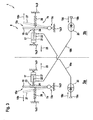
- Figure 3 shows the crossed by-pass air intake device control system 8 of Figure 1 of the aircraft 1, having the two gas turbine engines 3a, 3b of Figure 1 , in greater detail. More specifically, the by-pass air intake devices 74, 7b and the bleed air outlets 18a, 18b that are interconnected as described above with reference to Figure 1 are illustrated in greater detail.
- the gas turbine engines 3a, 3b are provided with similar general configurations, at least within predetermined manufacturing tolerances.
- the by-pass air intake 7a, 7b of each one of the gas turbine engines 3a, 3b is provided with a by-pass door hinge element 15c, with which the respective by-pass door 15 is pivotably mounted to the engine housing 9 of the respective gas turbine engine 3a, 3b or to the fuselage 1 a of the aircraft 1.
- each by-pass door 15 is connected by means of an associated piston connecting point 23 to a piston bearing 24, preferentially a ball bearing, which is mounted to an actuator piston 22.
- the latter is glidingly housed in an actuator housing 21 of the operating element 17, which is illustratively embodied as a pneumatic actuator and, therefore, also referred to as the "pneumatic actuator 17" hereinafter, for clarity.
- each by-pass door 15 is connected to an associated spring element 26 that is configured to spring-load the by-pass door 15.
- Each associated spring element 26 and each actuator housing 21 is mounted to the engine housing 9 of the respective gas turbine engine 3a, 3b or to the fuselage 1a of the aircraft 1.
- each associated spring element 26 is mounted to the respective gas turbine engine 3a, 3b or to the fuselage 1 a of the aircraft 1 such that it spring-loads the respective by-pass door 15 in the by-pass door opening direction 15b of Figure 2 into its opened position, in which the by-pass air inlet opening 15a is opened.
- the by-pass door 15 in its opened position is schematically indicated in broken lines and referred to with the reference sign 27.
- each pneumatic actuator 17 is mounted to the respective gas turbine engine 3a, 3b or to the fuselage 1a of the aircraft 1 such that it pulls the respective bypass door 15 in normal operation of the aircraft 1 in a by-pass door closing direction 25 into its closed position, in which the by-pass air inlet opening 15a is closed.
- each pneumatic actuator 17 retains the respective by-pass door 15 in normal operation of the aircraft 1 in its closed position.
- the pneumatic actuator 17 of the gas turbine engine 3a is connected to the bleed air outlet 18b of the gas turbine engine 3b by means of a connecting hose 19b, preferably via an associated air pressure accumulator 20.
- the pneumatic actuator 17 of the gas turbine engine 3b is connected to the bleed air outlet 18a of the gas turbine engine 3a by means of a connecting hose 19a, preferably also via an associated air pressure accumulator 20.
- the pneumatic actuator 17 of the gas turbine engine 3a is controllable by the outgoing bleed air stream 18d that goes out of the gas turbine engine 3b in operation
- the pneumatic actuator 17 of the gas turbine engine 3b is controllable by the outgoing bleed air stream 18c that goes out of the gas turbine engine 3a in operation.
- each one of the gas turbine engines 3a, 3b functions on the basis of the incoming main air stream 14a of Figure 2 . If, however, a given clogging rate of the inlet barrier filter 13 of one of the gas turbine engines 3a, 3b exceeds a predetermined threshold, the bleed air outlet 18a, 18b of this gas turbine engine 3a, 3b drives the pneumatic actuator 17 of the other one of the gas turbine engines 3b, 3a such that its by-pass door is moved to its opened position. Thus, a maximum air flow through the other one of the gas turbine engines 3b, 3a is established such that it provides a maximally available power output.
- the pneumatic actuator 17 of the gas turbine engine 3a opens the by-pass door 15 of the gas turbine engine 3a. Otherwise, if the clogging rate of the inlet barrier filter 13 of the gas turbine engine 3a exceeds the predetermined threshold, the pneumatic actuator 17 of the gas turbine engine 3b opens the by-pass door 15 of the gas turbine engine 3b.
- the pneumatic actuator of one of the gas turbine engines is adapted and mounted such that it pulls the respective by-pass door in normal operation to retain it in its closed position
- the pneumatic actuator of the other one of the gas turbine engines can be adapted and mounted such that it pushes the respective bypass door in normal operation to retain it in its closed position.
- the pneumatic actuator of each one of the gas turbine engines can be adapted and mounted such that it pushes the respective by-pass door in normal operation to retain it in its closed position. This likewise applies to the spring element of each one of the gas turbine engines 3a, 3b.
- a by-pass door blocking system can be provided that keeps the by-pass door of each one of the gas turbine engines 3a, 3b closed during cranking, i.e. starting of the engines. This can be useful in order to avoid foreign object damages of the gas turbine engines 3a, 3b during cranking.
- Such a by-pass door blocking system can further be adapted to keep the by-pass door of each one of the gas turbine engines 3a, 3b closed during parking of the aircraft 1, i.e. when the gas turbine engines 3a, 3b are shut down.
- the pneumatic actuator may not only be adapted to open the by-pass door, but may further be adapted for closing it, so that an underlying pneumatic mechanism has to be convertible.
- the above described spring elements could advantageously be omitted.
- so-called double-acting cylinders in rotating or piston design that use the force of the bleed air to move in both extends and retract strokes can be used therefore.
- a multi-port-valve can be used to manage the air flow to/from the pneumatic actuator, so that the by-pass door can be opened and closed as required.
Landscapes
- Engineering & Computer Science (AREA)
- Chemical & Material Sciences (AREA)
- Combustion & Propulsion (AREA)
- Mechanical Engineering (AREA)
- General Engineering & Computer Science (AREA)
- Aviation & Aerospace Engineering (AREA)
- Physics & Mathematics (AREA)
- Fluid Mechanics (AREA)
- Filtering Of Dispersed Particles In Gases (AREA)
Abstract
Description
- The invention is related to an aircraft having at least one first and one second engine, each engine comprising a main air inlet opening, a by-pass air inlet opening and a bleed air outlet, said aircraft comprising the features of
claim 1. - Main air inlet openings of engines in aircrafts and, more particularly, of gas turbine engines in aircrafts, such as e.g. turbo-shaft engines in rotary wing aircrafts, are frequently provided with inlet barrier filter systems comprising air filtration devices that are arranged in the main air paths of the engines for filtering main air streams through the main air inlet openings into the engines. Such inlet barrier filter systems offer a very effective possibility for protecting the engines. However, they are exposed to multiple different operating and background conditions, which may amongst others lead to a clogging of the air filtration devices after a certain time of operation. If this happens during flight operation, a respective power provided by an affected engine could potentially be decreased to an extent where the necessary power to safely continue operation would not be guaranteed any more.
- Accordingly, there are strict regulations for certification of inlet barrier filter systems, e.g. especially for so-called CAT A capable helicopters, i.e. helicopters corresponding to the category A definition of the EASA Comment Response Document CRD b.2 Annex I, which may lead to operational limitations for such helicopters. Therefore, already for certification purposes, the inlet barrier filter systems of such helicopters and, more generally, the inlet barrier filter systems on gas turbine engines of aircrafts in general, are provided with by-pass air systems that are adapted to feed the engines with air whenever a clogging of corresponding air filtration devices of the inlet barrier filter systems occurs during flight operation.
- In general, a by-pass air system of a gas turbine engine defines a secondary air path of the engine, which is realized without any air filtration device. More specifically, a by-pass air system of a gas turbine engine usually consists of a by-pass air inlet opening that is provided with a by-pass door, which is operable by an associated operating element, i.e. can be opened if required to enable a by-pass air stream through the by-pass air inlet opening into the engine.
- The above described by-pass air and main air inlet openings define air intake systems. However, gas turbine engines of aircrafts can also be provided with air outlet systems by means of so-called bleed air outlets for creating an outgoing bleed air stream going out of the engine in operation. Such bleed air outlets are generally arranged downstream of compressor stages of the gas turbine engines, which are upstream of their respective fuel burning sections, so that compressed air, the so-called "bleed air", can be derived from the gas turbine engines to form the outgoing bleed air stream. This outgoing bleed air stream can advantageously be used e.g. for cross-starting another engine, cabin pressurization, airframe and engine anti-icing, air conditioning and so on.
- The document
US 2007/0025838 A1 describes an aircraft and, more particularly, a helicopter having a gas turbine engine that is provided with an air induction system. The air induction system is provided with a housing having four openings that comprise primary entryways for receiving air and are located on top and lateral surfaces of the housing. A flat filter panel with a porous filter media is mounted across each opening to define an inlet barrier filter system. The housing further comprises two hollow extensions, each having an opening that, in turn, comprises a bypass opening for receiving intake air into the housing that supplements or replaces primary intake air received through the flat filter panels. A hinged door covers each by-pass opening and is controllably rotatable by a motorized actuator between a closed position, wherein the by-pass opening is closed, and an open position, wherein intake air may enter the housing through the bypass opening. The motorized actuator is implemented as an electromechanical actuator. - The document
WO 2008/016341 A2 describes an aircraft and, more particularly, a helicopter having a gas turbine engine that is also provided with an air induction system. The air induction system includes a cowling and a filtering unit that is generally enclosed within the cowling. The filtering unit comprises two barrier filter panels with pleated, porous barrier filter elements that are provided with filter media, such as cotton grid fabric, and arranged in a main air intake path for filtering main air streams prior to intake into the engines. The air induction system is further provided with one or more by-pass openings that are covered by associated hinged by-pass doors. Each hinged by-pass door is opened and closed by an actuator that is implemented as an electromechanical actuator. - The document
WO 2008/076471 A2 describes an inlet barrier filter system for an aircraft engine, which includes a filter panel with a filter media for filtering a main air stream prior to intake into the engine. The filter panel can be pivoted by means of an associated actuator to form a by-pass air inlet opening, such that air is allowed to bypass the filter panel for streaming via said bypass air inlet opening into the engine. In other words, the filter panel itself implements the by-pass door of the by-pass air inlet opening. The actuator is implemented as an electromechanical actuator. - The
document FR 1 548 724 A1 - The document
US 2013/0092798 A1 describes an aircraft and, more particularly, a helicopter having an aircraft engine that may include a turbine engine, a piston engine, or another type of engine suitable for generating rotation of associated rotor blades, in order to provide thrust for the aircraft. The aircraft engine includes two intakes for receiving air flow for use by the aircraft engine in a combustion process. The helicopter includes two filter systems that are respectively coupled to an associated one of the intakes, such that intake air passes through the filter system prior to entering the air intake of the aircraft engine. Each filter system includes a by-pass closure, which is disposed adjacent to a filter assembly of the filter system. The by-pass closure is movable relative to the filter assembly between a first position, in which the by-pass closure covers and seals the by-pass opening of the filter assembly, and a second position, in which the by-pass closure is spaced apart from the filter assembly. The filter system further includes an actuator for causing relative movement of the by-pass closure between the first and second positions. This actuator may include an electrical actuator, a fluid actuator, a pneumatic actuator or another suitable device. - The document
US 3,411,272 describes a helicopter with a turbine engine having an air inlet that is positioned to receive air from an inlet compartment or plenum. The air inlet is provided with a pair of fixed side filter assemblies and a movable top filter assembly. The side filter assemblies are positionally fixed to constantly provide filtering action. The top filter assembly is of a louvered construction including a plurality of fixed louvers and a plurality of pivotably movable louvers having filters, which can be of a conventional construction to capture harmful dirt particles, while passage of air is permitted. The movable louvers cooperate with the stationary louvers in a closed position to completely close the air inlet through an upper portion of the inlet compartment. The movable louvers are pivotally mounted at their lower extremities about associated pivots. Thus, the movable louvers can be pivoted into a position, in which a passage through the top filter assembly is opened, so that air will pass freely there through while bypassing the filters of the louvers. Movement of the movable louvers can be provided by means of an actuator that can be implemented by a pneumatic piston assembly, which can be actuated by a 4-way pneumatic valve, which in turn is actuated by an electric solenoid. The actuation of the solenoid, and hence the pneumatic valve and the movable louvers, is controlled by electrical circuitry. - However, in all of the above-described barrier inlet filter and/or by-pass air systems, a cumulated time of failure detection in the case of a failure of the aircraft engine, or a One Engine Inoperative (OEI)-detection in the case of a failure of an aircraft engine of a multi-engine aircraft, and a subsequent activation of the above described actuators in order to fully open respective bypass air inlet openings is comparatively long and can take up to six seconds. This applies particularly to electrical and/or electromechanical actuators, which usually further require provision of an associated harness system and additional electrical power supply systems, which makes the construction thereof comparatively complex.
- More generally, all of the above-described barrier inlet filter and/or by-pass air systems use actuating systems that are, at least to some extent, electrically operated or activated, so that they require provision of electrical power supply systems. Such electrical power supply systems and the complexity of the respective actuating systems are, however, themselves potential sources of error and failure.
- These drawbacks must be considered during construction of aircrafts with respect to flight and operation safety. They must further be considered with respect to certification of inlet barrier filter systems of aircrafts, especially with regard to the strict regulations for helicopters with the above mentioned capability for CAT A operation.
- It is, therefore, an object of the present invention to provide an aircraft that comprises at least one first and one second engine, each engine comprising a main air inlet opening, a by-pass air inlet opening and a bleed air outlet, and that overcomes the above described drawbacks.
- According to the invention, an aircraft having at least one first and one second engine is provided, wherein each engine comprises a main air inlet opening, a by-pass air inlet opening and a bleed air outlet. The main air inlet opening is provided with an inlet barrier filter for filtering a main air stream through said main air inlet opening into the engine. The by-pass air inlet opening is provided with a by-pass door that is operable by an associated operating element to enable a by-pass air stream through said bypass air inlet opening into the engine. The bleed air outlet is provided for creating an outgoing bleed air stream going out of the engine in operation. Furthermore, the associated operating element of the at least one first engine is connected to the bleed air outlet of the at least one second engine and controllable by the outgoing bleed air stream that goes out of the at least one second engine in operation, and the associated operating element of the at least one second engine is connected to the bleed air outlet of the at least one first engine and controllable by the outgoing bleed air stream that goes out of the at least one first engine in operation.
- Preferably, the outgoing bleed air stream of the at least one first engine is used to keep the by-pass door of the at least one second engine closed and the outgoing bleed air stream of the at least one second engine is used to keep the by-pass door of the at least one first engine closed. Accordingly, if e.g. the at least one first engine fails, a corresponding pressure of the outgoing bleed air stream of the at least one first engine would abruptly decrease so that this outgoing bleed air stream could not keep the by-pass door of the at least one second engine closed any more. Thus, the by-pass door of the at least one second engine is opened so that the latter is operated in order to generate a maximally available power output. Similarly, if e.g. the at least one second engine fails, a corresponding pressure of the outgoing bleed air stream of the at least one second engine would abruptly decrease so that this outgoing bleed air stream could not keep the by-pass door of the at least one first engine closed any more. Thus, the by-pass door of the at least one first engine is opened so that the latter is operated in order to generate a maximally available power output.
- Advantageously, the by-pass air system according to the invention has a simple mechanical/pneumatic construction that uses comparatively simple constituting components. Preferably, this by-pass air system does not require any electrical power supply, so that provision of an associated electrical power supply system and, thus, dedicated electrical wiring required for such an associated electrical power supply and control of corresponding, electrically controlled and driven actuators, can be omitted.
- Preferably, the inventive by-pass air system functions by means of bleed air that is re-routed from the at least one first and second engines and used to drive associated pneumatic actuators that are adapted to generate motion that can be rotary or linear, depending on the type of actuator, e.g. rod cylinder type or rotary type actuator. More specifically, the inventive by-pass air systems of the at least one first and second engines preferably use pneumatic actuators and/or lamellar motors and/or pressure rod cylinder units that are driven by compressed air, i.e. bleed air that is re-routed from the at least one first and second engines themselves.
- Bleed air is particularly advantageous and used on many aircraft systems, as it is easily available, reliable, and a potent source of power. For example, so-called air turbine starters that are used to start large gas turbine engines using bleed air can be designed much smaller and lighter than electric motors of equivalent power output. Furthermore, bleed air is available throughout the operating range of the engine from which it is re-routed and a bleed air outlet is serial standard for almost all gas turbine engines and, in particular, turbo-shaft engines that are intended for aeronautical application.
- Advantageously, the inventive by-pass air system with pneumatic actuators has less latency time in transition, compared to e.g. a by-pass system with electrical actuators, due to a potential for very fast operation. Thus, the inventive by-pass air system puts less restrictions on aircrafts that are equipped therewith, in particular on helicopters that are intended for certification for CAT A operation.
- According to one aspect of the invention, a by-pass door blocking system is provided that keeps the by-pass doors of the at least one first and second engines closed during cranking, i.e. starting of the engines. This can be useful in order to avoid foreign object damages of the at least one first and second engines during cranking.
- According to a preferred embodiment of the invention, the associated operating element of the at least one first engine is configured to open the by-pass door of the at least one first engine in operation at least if a given clogging rate of the inlet barrier filter of the at least one second engine exceeds a predetermined threshold. Preferably, the associated operating element of the at least one second engine is configured to open the by-pass door of the at least one second engine in operation at least if a given clogging rate of the inlet barrier filter of the at least one first engine exceeds a predetermined threshold.
- According to a further preferred embodiment of the invention, the associated operating element is a pneumatic actuator.
- According to a further preferred embodiment of the invention, the associated operating element of the at least one first engine is connected to the bleed air outlet of the at least one second engine by means of a first connecting hose, and the associated operating element of the at least one second engine is connected to the bleed air outlet of the at least one first engine by means of a second connecting hose.
- According to a further preferred embodiment of the invention, the associated operating element of the at least one first engine is connected to the bleed air outlet of the at least one second engine via a first associated air pressure accumulator, and the associated operating element of the at least one second engine is connected to the bleed air outlet of the at least one first engine via a second associated air pressure accumulator.
- According to a further preferred embodiment of the invention, said pneumatic actuator is a rod cylinder type actuator or a rotary type actuator.
- According to a further preferred embodiment of the invention, said by-pass door is spring-loaded by an associated spring element into an opened position and retained by said associated operating element in operation in a closed position.
- According to a further preferred embodiment of the invention, said by-pass door is configured to remain in closed position, if said engine is inactive.
- The present invention further provides an engine for an aircraft, comprising a main air inlet opening, a by-pass air inlet opening and a bleed air outlet. The main air inlet opening is provided with an inlet barrier filter for filtering a main air stream through said main air inlet opening into said engine. The by-pass air inlet opening is provided with a by-pass door that is operable by an associated operating element to enable a by-pass air stream through said by-pass air inlet opening into said engine. The bleed air outlet is provided for creating an outgoing bleed air stream going out of said engine in operation. Furthermore, the associated operating element is connected to said bleed air outlet and controllable by said outgoing bleed air stream in operation.
- According to one aspect of the invention, the engine is a gas turbine engine having an upstream rotating compressor, a combustion chamber and a downstream turbine. The main air inlet opening with the inlet barrier filter and the by-pass air inlet opening are preferably arranged upstream of and/or radial to the upstream rotating compressor, and the bleed air outlet is preferably arranged downstream of said upstream rotating compressor, but still upstream of the combustion chamber. The bleed air outlet is preferentially configured to re-route a comparatively small part of compressed air generated by the upstream rotating compressor via pneumatic hoses to a pneumatic piston or rotary motor which is adapted to open the by-pass door, if required. The comparatively small part of re-routed compressed air defines the so-called bleed air and even conventional gas turbine engines are usually already equipped with relevant interfaces, so that there are advantageously no structural engine modifications required to allow use of the bleed air stream when conventional gas turbine engines are used to implement the present invention.
- Preferably, the by-pass door is operated by an operating element that is implemented by means of pneumatic actuators, such as pneumatic motors or pressure cylinders, which will be driven by the bleed air stream. The pressure of the bleed air stream depends on a selected engine and can amount up to several hundred kPa, which can be matched with torque-output characteristic curves of readily available pneumatic actuators, so that conventional pneumatic actuators can advantageously be used when implementing the present invention. However, as the air temperature after the compressor stage, i.e. of the re-routed compressed air is roughly 250-300° Celsius depending on a selected engine, the pneumatic actuators need adequate sealing and housing.
- According to one aspect of the invention, the bleed air outlet of the engine is connected with a hose to the pneumatic actuator, which will drive the by-pass door. The by-pass door, or alternatively a by-pass flap, is preferentially opened when the inlet barrier filter is getting clogged or in case of an engine fire.
- Preferably, the pneumatic actuator is adapted to open and close the by-pass door, so that an underlying pneumatic mechanism has to be convertible. For instance, so-called double-acting cylinders in rotating or piston design that use the force of the bleed air to move in both extends and retract strokes can be used therefore. Suitable conventional double-acting cylinders are readily available and can advantageously be used without requiring structural modifications. Preferentially, a multi-port-valve can be used to manage the air flow to/from the pneumatic actuator, so that the by-pass door can be opened and closed as required.
- According to a preferred embodiment of the invention, said associated operating element is configured to open said by-pass door in operation at least if a given clogging rate of said inlet barrier filter exceeds a predetermined threshold.
- According to a further preferred embodiment of the invention, said associated operating element is a pneumatic actuator.
- According to a further preferred embodiment of the invention, said associated operating element is connected to said bleed air outlet by means of a connecting hose.
- According to a further preferred embodiment of the invention, said associated operating element is connected to said bleed air outlet via an associated air pressure accumulator.
- According to a further preferred embodiment of the invention, said pneumatic actuator is a rod cylinder type actuator or a rotary type actuator.
- According to a further preferred embodiment of the invention, said by-pass door is spring-loaded by an associated spring element into an opened position and retained by said associated operating element in operation in a closed position.
- According to a further preferred embodiment of the invention, said by-pass door is configured to remain in closed position, if said engine is inactive.
- Preferred embodiments of the invention are outlined by way of example in the following description with reference to the attached drawings. In these attached drawings, identical or identically functioning components and elements are labeled with identical reference sign and are, consequently, only described once in the following description.
-
Figure 1 shows a schematic view of an aircraft with a crossed by-pass air intake device control system according to a first embodiment of the invention, -
Figure 2 shows a schematic view of a gas turbine engine with an in-line by-pass air intake device control system according to a second embodiment of the invention, and -
Figure 3 shows the crossed by-pass air intake device control system ofFigure 1 in greater detail. -
Figure 1 shows anaircraft 1 with afuselage 1a according to the invention. Theaircraft 1 is preferentially equipped with at least one and, illustratively, twoaircraft engines aircraft engines air inlet openings air intake devices air outlets - According to one aspect of the invention, the
aircraft 1 is a rotary wing aircraft havingrotary wings 2a, and the twogas turbine engines power consumer units 2 that are illustratively defined by therotary wings 2a. More specifically, therotary wings 2a are propelled by a propulsion system that comprises the twogas turbine engines gas turbine engines input interface 4, such as amechanical shaft 4, hydraulic and/or electric means to amain gearbox 5. Themain gearbox 5 transmits the power received from thegas turbine engines rotary wings 2a in order to propel the latter. - However, it should be noted that the present invention is not limited to rotary wing aircrafts. Instead, the present invention can be applied to any aircraft that comprises gas turbine engines with associated main air inlet openings, by-pass air intake devices and bleed air outlets.
- According to one embodiment of the invention, the
aircraft 1 comprises a by-pass air intake device control system 8 that interconnects the by-passair intake devices bleed air outlets gas turbine engines air intake device 7a of thegas turbine engine 3a is interconnected with thebleed air outlet 18b of thegas turbine engine 3b, and wherein the by-passair intake device 7b of thegas turbine engine 3b is interconnected with thebleed air outlet 18a of thegas turbine engine 3a. The by-pass air intake device control system 8 is, therefore, also referred to as the "crossed by-pass air intake device control system 8", for clarity. - The crossed by-pass air intake device control system 8 is described in more detail below with reference to
Fig. 3 . However, it should be noted that the invention is not limited to such a crossed by-pass air intake device control system 8 that interconnects the twogas turbine engines gas turbine engines Figure 2 . -
Figure 2 shows thegas turbine engine 3a ofFigure 1 with the mainair inlet opening 9a, the by-passair intake device 7a and thebleed air outlet 18a. According to one embodiment, thegas turbine engine 3a comprises anengine housing 9 that accommodates, amongst others, an upstreamrotating compressor 10 that is adapted to compress an incomingmain air stream 14a, acombustion chamber 11 that is adapted to combust fuel using themain air stream 14a, and adownstream turbine 12 that is adapted to exhaust anoutgoing air stream 14b. - Preferably upstream of and/or radial to the upstream
rotating compressor 10, the mainair inlet opening 9a and the by-passair intake device 7a are arranged. Furthermore, downstream of the upstreamrotating compressor 10, but still upstream of thecombustion chamber 11, thebleed air outlet 18a is arranged. - The main
air inlet opening 9a is provided with aninlet barrier filter 13, which can comprise any suitable filter material, for filtering themain air stream 14a through the main air inlet opening 9a into thegas turbine engine 3a and, more particularly, into the upstreamrotating compressor 10. The by-passair intake device 7a preferably comprises at least one by-passair inlet opening 15a that is provided with a by-pass door 15. The latter is preferably configured to remain in closed position, if thegas turbine engine 3a is inactive, and preferentially operable by an associatedoperating element 17 to enable a by-pass air stream 16 through the by-pass air inlet opening 15a into thegas turbine engine 3a, if required. Thebleed air outlet 18a is preferentially configured to re-route at least a comparatively small part of compressed air generated by the upstreamrotating compressor 10 for creating an outgoingbleed air stream 18c that goes out of thegas turbine engine 3a in operation. - It should be noted that the above configuration of the
gas turbine engine 3a as described so far is well-known to the person skilled in the art. Therefore, thegas turbine engine 3a is only illustrated roughly and schematically inFigure 2 and not shown in greater detail. - It should further be noted that the described
gas turbine engine 3a is also representative of thegas turbine engine 3b ofFigure 1 . In other words, thegas turbine engine 3b ofFigure 1 is preferably configured similar to thegas turbine engine 3a, at least within predetermined manufacturing tolerances. - According to one embodiment, the associated operating
element 17 that is provided for operation of the by-pass door 15 is connected to thebleed air outlet 18a by means of a by-pass air intakedevice control system 28. As this by-pass air intakedevice control system 28 interconnects the operatingelement 17 and thebleed air outlet 18a of the same gas turbine engine, i.e. thegas turbine engine 3a - in contrast to the crossed by-pass air intake device control system 8 ofFigure 1 -, it is referred to in the present application as the "in-line by-pass air intakedevice control system 28", for clarity. - Preferably, the in-tine by-pass air intake
device control system 28 interconnects the operatingelement 17 and thebleed air outlet 18a of thegas turbine engine 3a such that the operatingelement 17 is controllable by the outgoingbleed air stream 18c that goes out of thebleed air outlet 18a in operation. In order to enable such a control by the outgoingbleed air stream 18c, the associated operatingelement 17 is preferentially a pneumatic actuator, such as a rod cylinder type actuator or a rotary type actuator. - According to one aspect of the invention, the in-line by-pass air intake
device control system 28 comprises a connectinghose 19 that connects thebleed air outlet 18a to theoperating element 17, which is configured to open or to allow opening of the by-pass door 15 in operation, e.g. in a by-passdoor opening direction 15b, at least if a given clogging rate of theinlet barrier filter 13 exceeds a predetermined threshold. The in-line by-pass air intakedevice control system 28 may further comprise an associated air pressure accumulator (20 inFigure 3 ). According to one embodiment, the by-pass door 15 is spring-loaded by an associated spring element (26 inFigure 3 ) into an opened position and retained by the associated operatingelement 17 in operation in a closed position. - In operation of the gas turbine engine, when e.g. a given clogging rate of the
inlet barrier filter 13 exceeds a predetermined threshold, pressure and streaming volume of the incoming main air stream 14 decreases and, consequently, also pressure and streaming volume of the outgoingbleed air stream 18c decreases. Thus, the associated operatingelement 17 cannot retain thebypass door 15 in its closed position, so that the spring-load of the associated spring element (26 inFigure 3 ) suffices to move thebypass door 15 in the by-passdoor opening direction 15b into its opened position, so that the by-pass air stream 16 can stream through the by-pass air inlet opening 15a into thegas turbine engine 3a. -
Figure 3 shows the crossed by-pass air intake device control system 8 ofFigure 1 of theaircraft 1, having the twogas turbine engines Figure 1 , in greater detail. More specifically, the by-passair intake devices 74, 7b and thebleed air outlets Figure 1 are illustrated in greater detail. - As was mentioned above, the
gas turbine engines pass air intake gas turbine engines door hinge element 15c, with which the respective by-pass door 15 is pivotably mounted to theengine housing 9 of the respectivegas turbine engine fuselage 1 a of theaircraft 1. - Preferably, each by-
pass door 15 is connected by means of an associatedpiston connecting point 23 to apiston bearing 24, preferentially a ball bearing, which is mounted to anactuator piston 22. The latter is glidingly housed in anactuator housing 21 of the operatingelement 17, which is illustratively embodied as a pneumatic actuator and, therefore, also referred to as the "pneumatic actuator 17" hereinafter, for clarity. Furthermore, each by-pass door 15 is connected to an associatedspring element 26 that is configured to spring-load the by-pass door 15. Each associatedspring element 26 and eachactuator housing 21 is mounted to theengine housing 9 of the respectivegas turbine engine fuselage 1a of theaircraft 1. - In the illustrated embodiment, each associated
spring element 26 is mounted to the respectivegas turbine engine fuselage 1 a of theaircraft 1 such that it spring-loads the respective by-pass door 15 in the by-passdoor opening direction 15b ofFigure 2 into its opened position, in which the by-passair inlet opening 15a is opened. The by-pass door 15 in its opened position is schematically indicated in broken lines and referred to with thereference sign 27. Furthermore, eachpneumatic actuator 17 is mounted to the respectivegas turbine engine fuselage 1a of theaircraft 1 such that it pulls therespective bypass door 15 in normal operation of theaircraft 1 in a by-passdoor closing direction 25 into its closed position, in which the by-passair inlet opening 15a is closed. Preferably, eachpneumatic actuator 17 retains the respective by-pass door 15 in normal operation of theaircraft 1 in its closed position. - According to one aspect of the invention, the
pneumatic actuator 17 of thegas turbine engine 3a is connected to thebleed air outlet 18b of thegas turbine engine 3b by means of a connectinghose 19b, preferably via an associatedair pressure accumulator 20. Similarly, thepneumatic actuator 17 of thegas turbine engine 3b is connected to thebleed air outlet 18a of thegas turbine engine 3a by means of a connectinghose 19a, preferably also via an associatedair pressure accumulator 20. Thus, thepneumatic actuator 17 of thegas turbine engine 3a is controllable by the outgoingbleed air stream 18d that goes out of thegas turbine engine 3b in operation, and thepneumatic actuator 17 of thegas turbine engine 3b is controllable by the outgoingbleed air stream 18c that goes out of thegas turbine engine 3a in operation. - More specifically, in normal operation of the
aircraft 1, when bothgas turbine engines rotary wings 2a ofFigure 1 , each one of thegas turbine engines main air stream 14a ofFigure 2 . If, however, a given clogging rate of theinlet barrier filter 13 of one of thegas turbine engines bleed air outlet gas turbine engine pneumatic actuator 17 of the other one of thegas turbine engines gas turbine engines - In other words, if the clogging rate of the
inlet barrier filter 13 of thegas turbine engine 3b exceeds the predetermined threshold, thepneumatic actuator 17 of thegas turbine engine 3a opens the by-pass door 15 of thegas turbine engine 3a. Otherwise, if the clogging rate of theinlet barrier filter 13 of thegas turbine engine 3a exceeds the predetermined threshold, thepneumatic actuator 17 of thegas turbine engine 3b opens the by-pass door 15 of thegas turbine engine 3b. - It should be noted that the above operation is only described by way of example with respect to a clogging of an inlet barrier filter of one of the
gas turbine engines gas turbine engines gas turbine engines gas turbine engines - It should further be noted that the constituting components of the
gas turbine engines Figure 3 are designated with identical reference signs for simplicity and as they convey an identical functioning. However, it should be clear to the person skilled in the art that each one of thegas turbine engines - It should also be noted that the above described, preferred embodiments are merely described to illustrate possible embodiments of the present invention, but not in order to restrict the present invention thereto. Instead, multiple modifications and variations of the invention are possible and should, therefore, also be considered as being part of the invention. In particular, while the configurations of the
gas turbine engines Figure 3 , the pneumatic actuator of the other one of the gas turbine engines can be adapted and mounted such that it pushes the respective bypass door in normal operation to retain it in its closed position. Still alternatively, the pneumatic actuator of each one of the gas turbine engines can be adapted and mounted such that it pushes the respective by-pass door in normal operation to retain it in its closed position. This likewise applies to the spring element of each one of thegas turbine engines - Furthermore, a by-pass door blocking system can be provided that keeps the by-pass door of each one of the
gas turbine engines gas turbine engines gas turbine engines aircraft 1, i.e. when thegas turbine engines - Moreover, the pneumatic actuator may not only be adapted to open the by-pass door, but may further be adapted for closing it, so that an underlying pneumatic mechanism has to be convertible. In this case, the above described spring elements could advantageously be omitted. For instance, so-called double-acting cylinders in rotating or piston design that use the force of the bleed air to move in both extends and retract strokes can be used therefore. Furthermore, a multi-port-valve can be used to manage the air flow to/from the pneumatic actuator, so that the by-pass door can be opened and closed as required.
-
- 1
- aircraft
- 1a
- fuselage
- 2
- power consumer unit
- 3a, 3b
- aircraft engines
- 4
- link from aircraft engines to main gearbox
- 5
- main gearbox
- 6
- power consumer shaft
- 7a, 7b
- by-pass air intake devices
- 8
- crossed by-pass air intake device control system
- 9
- engine housing
- 9a, 9b
- main air inlet openings
- 10
- upstream rotating compressor
- 11
- combustion chamber
- 12
- downstream turbine
- 13
- inlet barrier filter
- 14a
- incoming air stream
- 14b
- outgoing air stream
- 15
- by-pass door
- 15a
- by-pass air inlet opening
- 15b
- by-pass door opening direction
- 15c
- by-pass door hinge element
- 16
- incoming by-pass air stream
- 17
- by-pass door actuator
- 18a, 18b
- bleed air outlets
- 18c, 18d
- bleed air streams
- 19, 19a, 19b
- connecting hoses
- 20
- air pressure accumulators
- 21
- by-pass door actuator housing
- 22
- actuator piston
- 23
- piston connecting point
- 24
- ball bearing
- 25
- by-pass door closing direction
- 26
- opening springs
- 27
- opened by-pass door
- 28
- in-line by-pass air intake device control system
Claims (16)
- An aircraft (1) having at least one first and one second engine (3a, 3b), each engine (3a, 3b) comprising a main air inlet opening (9a, 9b), a by-pass air inlet opening (15a) and a bleed air outlet (18a, 18b), said main air inlet opening (9a, 9b) being provided with an inlet barrier filter (13) for filtering a main air stream (14a) through said main air inlet opening (9a, 9b) into the engine (3a, 3b), said by-pass air inlet opening (15a) being provided with a by-pass door (15) that is operable by an associated operating element (17) to enable a by-pass air stream (16) through said by-pass air inlet opening (15a) into the engine (3a, 3b), and said bleed air outlet (18a, 18b) being provided for creating an outgoing bleed air stream (18c, 18d) going out of the engine (3a, 3b) in operation, characterized in that the associated operating element (17) of the at least one first engine (3a) is connected to the bleed air outlet (18b) of the at least one second engine (3b) and controllable by the outgoing bleed air stream (18d) that goes out of the at least one second engine (3b) in operation, and the associated operating element (17) of the at least one second engine (3b) is connected to the bleed air outlet (18a) of the at least one first engine (3a) and controllable by the outgoing bleed air stream (18c) that goes out of the at least one first engine (3a) in operation.
- The aircraft (1) according to claim 1, characterized in that the associated operating element (17) of the at least one first engine (3a) is configured to open the by-pass door (15) of the at least one first engine (3a) in operation at least if a given clogging rate of the inlet barrier filter (13) of the at least one second engine (3b) exceeds a predetermined threshold, and the associated operating element (17) of the at least one second engine (3b) is configured to open the by-pass door (15) of the at least one second engine (3b) in operation at least if a given clogging rate of the inlet barrier filter (13) of the at least one first engine (3a) exceeds a predetermined threshold.
- The aircraft (1) according to claim 1, characterized in that the associated operating element (17) is a pneumatic actuator.
- The aircraft (1) according to claim 3, characterized in that the associated operating element (17) of the at least one first engine (3a) is connected to the bleed air outlet (18b) of the at least one second engine (3b) by means of a first connecting hose (19b), and the associated operating element (17) of the at least one second engine (3b) is connected to the bleed air outlet (18a) of the at least one first engine (3a) by means of a second connecting hose (19a).
- The aircraft (1) according to claim 3, characterized in that the associated operating element (17) of the at least one first engine (3a) is connected to the bleed air outlet (18b) of the at least one second engine (3b) via a first associated air pressure accumulator (20), and the associated operating element (17) of the at least one second engine (3b) is connected to the bleed air outlet (18a) of the at least one first engine (3a) via a second associated air pressure accumulator (20).
- The aircraft (1) according to claim 3, characterized in that said pneumatic actuator (17) is a rod cylinder type actuator or a rotary type actuator.
- The aircraft (1) according to claim 1, characterized in that said by-pass door (15) is spring-loaded by an associated spring element (26) into an opened position and retained by said associated operating element (17) in operation in a closed position.
- The aircraft (1) according to claim 1, characterized in that said by-pass door (15) is configured to remain in closed position, if said engine (3a, 3b) is inactive.
- An engine (3a) for an aircraft (1), comprising a main air inlet opening (9a), a by-pass air inlet opening (15a) and a bleed air outlet (18a), said main air inlet opening (9a) being provided with an inlet barrier filter (13) for filtering a main air stream (14a) through said main air inlet opening (9a) into said engine (3a), said by-pass air inlet opening (15a) being provided with a by-pass door (15) that is operable by an associated operating element (17) to enable a by-pass air stream (16) through said by-pass air inlet opening (15a) into said engine (3a), and said bleed air outlet (18a) being provided for creating an outgoing bleed air stream (18c) going out of said engine (3a) in operation, characterized in that said associated operating element (17) is connected to said bleed air outlet (18a) and controllable by said outgoing bleed air stream (18c) in operation.
- The engine (3a) according to claim 9, characterized in that said associated operating element (17) is configured to open said by-pass door (15) in operation at least if a given clogging rate of said inlet barrier filter (13) exceeds a predetermined threshold.
- The engine (3a) according to claim 9, characterized in that said associated operating element (17) is a pneumatic actuator.
- The engine (3a) according to claim 11, characterized in that said associated operating element (17) is connected to said bleed air outlet (18a) by means of a connecting hose (19).
- The engine (3a) according to claim 11, characterized in that said associated operating element (17) is connected to said bleed air outlet (18a) via an associated air pressure accumulator (20).
- The engine (3a) according to claim 11, characterized in that said pneumatic actuator (17) is a rod cylinder type actuator or a rotary type actuator.
- The engine (3a) according to claim 9, characterized in that said by-pass door (15) is spring-loaded by an associated spring element (26) into an opened position and retained by said associated operating element (17) in operation in a closed position.
- The engine (3a) according to claim 9, characterized in that said by-pass door (15) is configured to remain in closed position, if said engine (3a) is inactive.
Priority Applications (3)
| Application Number | Priority Date | Filing Date | Title |
|---|---|---|---|
| EP14400038.7A EP2957503B1 (en) | 2014-06-19 | 2014-06-19 | Aircraft with two engines having by-pass air inlet openings and bleed air outlets as well as engine for an aircraft |
| CA2888262A CA2888262C (en) | 2014-06-19 | 2015-04-15 | Aircraft with an engine having a by-pass air inlet opening and a bleed air outlet |
| US14/730,367 US9902500B2 (en) | 2014-06-19 | 2015-06-04 | Aircraft with an engine having a by-pass air inlet opening and a bleed air outlet |
Applications Claiming Priority (1)
| Application Number | Priority Date | Filing Date | Title |
|---|---|---|---|
| EP14400038.7A EP2957503B1 (en) | 2014-06-19 | 2014-06-19 | Aircraft with two engines having by-pass air inlet openings and bleed air outlets as well as engine for an aircraft |
Publications (2)
| Publication Number | Publication Date |
|---|---|
| EP2957503A1 true EP2957503A1 (en) | 2015-12-23 |
| EP2957503B1 EP2957503B1 (en) | 2016-08-17 |
Family
ID=51518732
Family Applications (1)
| Application Number | Title | Priority Date | Filing Date |
|---|---|---|---|
| EP14400038.7A Active EP2957503B1 (en) | 2014-06-19 | 2014-06-19 | Aircraft with two engines having by-pass air inlet openings and bleed air outlets as well as engine for an aircraft |
Country Status (3)
| Country | Link |
|---|---|
| US (1) | US9902500B2 (en) |
| EP (1) | EP2957503B1 (en) |
| CA (1) | CA2888262C (en) |
Cited By (2)
| Publication number | Priority date | Publication date | Assignee | Title |
|---|---|---|---|---|
| EP3822172A1 (en) * | 2019-11-14 | 2021-05-19 | Airbus Helicopters | System for controlling a check valve of an aircraft, aircraft provided with such a control system and associated control method |
| IT202200015141A1 (en) * | 2022-07-19 | 2024-01-19 | Bmc Srl | AIR INTAKE UNIT FOR A VEHICLE POWERTRAIN |
Families Citing this family (10)
| Publication number | Priority date | Publication date | Assignee | Title |
|---|---|---|---|---|
| CN105822433B (en) * | 2016-03-11 | 2017-10-20 | 奇瑞汽车股份有限公司 | A kind of aero-engine redundancy ECU controllers and its control method |
| US10889384B2 (en) | 2017-09-20 | 2021-01-12 | Textron Innovations Inc. | Rotorcraft engine inlet configuration to optimize performance in both hover and high speed flight |
| US11111024B2 (en) * | 2018-01-12 | 2021-09-07 | Honeywell International Inc. | Foldable RAM air inlet filter |
| US11274599B2 (en) | 2019-03-27 | 2022-03-15 | Pratt & Whitney Canada Corp. | Air system switching system to allow aero-engines to operate in standby mode |
| US11391219B2 (en) | 2019-04-18 | 2022-07-19 | Pratt & Whitney Canada Corp. | Health monitor for air switching system |
| US11274611B2 (en) | 2019-05-31 | 2022-03-15 | Pratt & Whitney Canada Corp. | Control logic for gas turbine engine fuel economy |
| US11859563B2 (en) | 2019-05-31 | 2024-01-02 | Pratt & Whitney Canada Corp. | Air system of multi-engine aircraft |
| US11555456B2 (en) | 2019-07-24 | 2023-01-17 | Pratt & Whitney Canada Corp. | Fuel delivery system and method |
| US11326525B2 (en) | 2019-10-11 | 2022-05-10 | Pratt & Whitney Canada Corp. | Aircraft bleed air systems and methods |
| CN111261458B (en) * | 2020-03-08 | 2022-06-07 | 陕西航空电气有限责任公司 | Contactor control method adopting non-similar dual processors in aviation power distribution system |
Citations (8)
| Publication number | Priority date | Publication date | Assignee | Title |
|---|---|---|---|---|
| US3411272A (en) | 1966-02-07 | 1968-11-19 | Michigan Dynamics Inc | Automatic fluid bypass sensing, actuating, and indicating system |
| FR1548724A (en) | 1966-11-15 | 1968-12-06 | ||
| US4250703A (en) * | 1979-03-15 | 1981-02-17 | Avco Corporation | Swinging door particle separator and deicing system |
| US20050229558A1 (en) * | 2004-04-14 | 2005-10-20 | Aerospace Filtration Systems, Inc. | Engine air filter and sealing system |
| US20070025838A1 (en) | 2005-07-29 | 2007-02-01 | Aerospace Filtration Systems, Inc. | Control of engine intake door |
| WO2008016341A2 (en) | 2005-05-31 | 2008-02-07 | Aerospace Filtration Systems, Inc. | Engine intake system with accessible, interchangeable air filters |
| WO2008076471A2 (en) | 2006-07-14 | 2008-06-26 | Aerospace Filtration Systems, Inc. | Aircraft engine inlet pivotable barrier filter |
| US20130092798A1 (en) | 2011-10-17 | 2013-04-18 | Aerospace Filtration Systems, Inc. | Filter Systems For Air Intakes Of Aircraft Engines and Related Methods |
Family Cites Families (11)
| Publication number | Priority date | Publication date | Assignee | Title |
|---|---|---|---|---|
| US2385366A (en) * | 1938-04-19 | 1945-09-25 | Jarvis C Marble | Power plant for aircraft |
| FR995990A (en) * | 1945-04-04 | 1951-12-11 | Rateau Soc | Improvement in gas turbines driving an overhead propeller |
| US3108767A (en) * | 1960-03-14 | 1963-10-29 | Rolls Royce | By-pass gas turbine engine with air bleed means |
| US3421296A (en) * | 1966-11-15 | 1969-01-14 | United Aircraft Corp | Engine inlet air particle separator |
| US4329114A (en) * | 1979-07-25 | 1982-05-11 | The United States Of America As Represented By The Administrator Of The National Aeronautics And Space Administration | Active clearance control system for a turbomachine |
| US5540252A (en) * | 1994-07-21 | 1996-07-30 | United Technologies Corporation | Pneumatically stabilized inline valve |
| CA2133793A1 (en) * | 1994-10-06 | 1996-04-07 | William E. Carscallen | Inter compressor duct variable geometry annular diffuser/bleed valve |
| US5662292A (en) * | 1995-05-03 | 1997-09-02 | Greene; Andrew T. | Helicopter engine filter system |
| US6152978A (en) * | 1996-02-02 | 2000-11-28 | Pall Corporation | Soot filter |
| US7607308B2 (en) * | 2005-12-08 | 2009-10-27 | General Electric Company | Shrouded turbofan bleed duct |
| US7946104B2 (en) * | 2006-05-12 | 2011-05-24 | Rohr, Inc. | Bleed air relief system for engines |
-
2014
- 2014-06-19 EP EP14400038.7A patent/EP2957503B1/en active Active
-
2015
- 2015-04-15 CA CA2888262A patent/CA2888262C/en active Active
- 2015-06-04 US US14/730,367 patent/US9902500B2/en active Active
Patent Citations (8)
| Publication number | Priority date | Publication date | Assignee | Title |
|---|---|---|---|---|
| US3411272A (en) | 1966-02-07 | 1968-11-19 | Michigan Dynamics Inc | Automatic fluid bypass sensing, actuating, and indicating system |
| FR1548724A (en) | 1966-11-15 | 1968-12-06 | ||
| US4250703A (en) * | 1979-03-15 | 1981-02-17 | Avco Corporation | Swinging door particle separator and deicing system |
| US20050229558A1 (en) * | 2004-04-14 | 2005-10-20 | Aerospace Filtration Systems, Inc. | Engine air filter and sealing system |
| WO2008016341A2 (en) | 2005-05-31 | 2008-02-07 | Aerospace Filtration Systems, Inc. | Engine intake system with accessible, interchangeable air filters |
| US20070025838A1 (en) | 2005-07-29 | 2007-02-01 | Aerospace Filtration Systems, Inc. | Control of engine intake door |
| WO2008076471A2 (en) | 2006-07-14 | 2008-06-26 | Aerospace Filtration Systems, Inc. | Aircraft engine inlet pivotable barrier filter |
| US20130092798A1 (en) | 2011-10-17 | 2013-04-18 | Aerospace Filtration Systems, Inc. | Filter Systems For Air Intakes Of Aircraft Engines and Related Methods |
Cited By (5)
| Publication number | Priority date | Publication date | Assignee | Title |
|---|---|---|---|---|
| EP3822172A1 (en) * | 2019-11-14 | 2021-05-19 | Airbus Helicopters | System for controlling a check valve of an aircraft, aircraft provided with such a control system and associated control method |
| FR3103177A1 (en) * | 2019-11-14 | 2021-05-21 | Airbus Helicopters | Control system for a shutter valve of an aircraft, aircraft equipped with such a control system and associated control method |
| US11220350B2 (en) | 2019-11-14 | 2022-01-11 | Airbus Helicopters | Control system for controlling a shut-off valve of an aircraft, an aircraft equipped with such a control system, and an associated control method |
| IT202200015141A1 (en) * | 2022-07-19 | 2024-01-19 | Bmc Srl | AIR INTAKE UNIT FOR A VEHICLE POWERTRAIN |
| US12352227B2 (en) | 2022-07-19 | 2025-07-08 | Bmc S.R.L. | Air intake unit for a vehicle engine |
Also Published As
| Publication number | Publication date |
|---|---|
| US9902500B2 (en) | 2018-02-27 |
| CA2888262C (en) | 2017-01-03 |
| US20150367945A1 (en) | 2015-12-24 |
| CA2888262A1 (en) | 2015-12-19 |
| EP2957503B1 (en) | 2016-08-17 |
Similar Documents
| Publication | Publication Date | Title |
|---|---|---|
| EP2957503B1 (en) | Aircraft with two engines having by-pass air inlet openings and bleed air outlets as well as engine for an aircraft | |
| US11077957B2 (en) | Selectable barrier filtration system | |
| EP3281876B1 (en) | Inlet duct selector for tiltrotor barrier filter | |
| US9517842B2 (en) | Filters for aircraft engine inlets | |
| EP1847458B1 (en) | Diffusing air inlet door assembly | |
| EP3385510A1 (en) | Control method for operating a precooler in an aircraft and aircraft engine | |
| EP2423488A2 (en) | Fuel actuated bleed air system | |
| KR102122624B1 (en) | Device and method for temporarily increasing power | |
| EP2987985A1 (en) | Actively controlled cooling air exhaust door on aircraft engine nacelle | |
| EP2743178A1 (en) | An air inlet combining a filter and a bypass device for use with a turbine engine | |
| CN110506156A (en) | Trhrust-reversal device flow-limiting valve | |
| EP2860113A1 (en) | Engine mounted inlet plenum for a rotorcraft | |
| CN109131900A (en) | The method of anti-thruster component and operation aircraft for aircraft | |
| US20240271564A1 (en) | Inlet air management system | |
| CA2510218A1 (en) | Hingeless flapper valve for flow control | |
| US11542028B2 (en) | Aircraft comprising an air intake | |
| EP3170750A1 (en) | Bi-fold thrust recovery outflow valve with a ram air flap | |
| CN102395777B (en) | Thrust reversal device | |
| EP3392150B1 (en) | Variable-geometry boundary layer diverter | |
| US10829237B2 (en) | Tiltrotor aircraft inlet-barrier filter method and apparatus | |
| EP4617484A1 (en) | Air inlet barrier filter for a helicopter | |
| EP3023330B1 (en) | Heat exchanger assembly for aircraft ecs | |
| CN110027714B (en) | Foldable ram air inlet filter | |
| US20110057141A1 (en) | Poppet valve for cabin pressure control systems | |
| US12234024B2 (en) | Ram filter purge system |
Legal Events
| Date | Code | Title | Description |
|---|---|---|---|
| PUAI | Public reference made under article 153(3) epc to a published international application that has entered the european phase |
Free format text: ORIGINAL CODE: 0009012 |
|
| 17P | Request for examination filed |
Effective date: 20150206 |
|
| AK | Designated contracting states |
Kind code of ref document: A1 Designated state(s): AL AT BE BG CH CY CZ DE DK EE ES FI FR GB GR HR HU IE IS IT LI LT LU LV MC MK MT NL NO PL PT RO RS SE SI SK SM TR |
|
| AX | Request for extension of the european patent |
Extension state: BA ME |
|
| GRAP | Despatch of communication of intention to grant a patent |
Free format text: ORIGINAL CODE: EPIDOSNIGR1 |
|
| RIC1 | Information provided on ipc code assigned before grant |
Ipc: F02C 9/18 20060101ALI20160321BHEP Ipc: F02C 7/057 20060101ALI20160321BHEP Ipc: F02C 6/08 20060101ALI20160321BHEP Ipc: F02C 7/055 20060101ALI20160321BHEP Ipc: B64D 33/02 20060101AFI20160321BHEP |
|
| INTG | Intention to grant announced |
Effective date: 20160428 |
|
| GRAS | Grant fee paid |
Free format text: ORIGINAL CODE: EPIDOSNIGR3 |
|
| GRAA | (expected) grant |
Free format text: ORIGINAL CODE: 0009210 |
|
| AK | Designated contracting states |
Kind code of ref document: B1 Designated state(s): AL AT BE BG CH CY CZ DE DK EE ES FI FR GB GR HR HU IE IS IT LI LT LU LV MC MK MT NL NO PL PT RO RS SE SI SK SM TR |
|
| REG | Reference to a national code |
Ref country code: GB Ref legal event code: FG4D |
|
| REG | Reference to a national code |
Ref country code: CH Ref legal event code: EP |
|
| REG | Reference to a national code |
Ref country code: IE Ref legal event code: FG4D |
|
| REG | Reference to a national code |
Ref country code: AT Ref legal event code: REF Ref document number: 820790 Country of ref document: AT Kind code of ref document: T Effective date: 20160915 |
|
| REG | Reference to a national code |
Ref country code: DE Ref legal event code: R096 Ref document number: 602014003122 Country of ref document: DE |
|
| REG | Reference to a national code |
Ref country code: NL Ref legal event code: MP Effective date: 20160817 |
|
| REG | Reference to a national code |
Ref country code: LT Ref legal event code: MG4D |
|
| REG | Reference to a national code |
Ref country code: AT Ref legal event code: MK05 Ref document number: 820790 Country of ref document: AT Kind code of ref document: T Effective date: 20160817 |
|
| PG25 | Lapsed in a contracting state [announced via postgrant information from national office to epo] |
Ref country code: NL Free format text: LAPSE BECAUSE OF FAILURE TO SUBMIT A TRANSLATION OF THE DESCRIPTION OR TO PAY THE FEE WITHIN THE PRESCRIBED TIME-LIMIT Effective date: 20160817 Ref country code: HR Free format text: LAPSE BECAUSE OF FAILURE TO SUBMIT A TRANSLATION OF THE DESCRIPTION OR TO PAY THE FEE WITHIN THE PRESCRIBED TIME-LIMIT Effective date: 20160817 Ref country code: LT Free format text: LAPSE BECAUSE OF FAILURE TO SUBMIT A TRANSLATION OF THE DESCRIPTION OR TO PAY THE FEE WITHIN THE PRESCRIBED TIME-LIMIT Effective date: 20160817 Ref country code: FI Free format text: LAPSE BECAUSE OF FAILURE TO SUBMIT A TRANSLATION OF THE DESCRIPTION OR TO PAY THE FEE WITHIN THE PRESCRIBED TIME-LIMIT Effective date: 20160817 Ref country code: RS Free format text: LAPSE BECAUSE OF FAILURE TO SUBMIT A TRANSLATION OF THE DESCRIPTION OR TO PAY THE FEE WITHIN THE PRESCRIBED TIME-LIMIT Effective date: 20160817 Ref country code: IT Free format text: LAPSE BECAUSE OF FAILURE TO SUBMIT A TRANSLATION OF THE DESCRIPTION OR TO PAY THE FEE WITHIN THE PRESCRIBED TIME-LIMIT Effective date: 20160817 Ref country code: NO Free format text: LAPSE BECAUSE OF FAILURE TO SUBMIT A TRANSLATION OF THE DESCRIPTION OR TO PAY THE FEE WITHIN THE PRESCRIBED TIME-LIMIT Effective date: 20161117 |
|
| PG25 | Lapsed in a contracting state [announced via postgrant information from national office to epo] |
Ref country code: ES Free format text: LAPSE BECAUSE OF FAILURE TO SUBMIT A TRANSLATION OF THE DESCRIPTION OR TO PAY THE FEE WITHIN THE PRESCRIBED TIME-LIMIT Effective date: 20160817 Ref country code: GR Free format text: LAPSE BECAUSE OF FAILURE TO SUBMIT A TRANSLATION OF THE DESCRIPTION OR TO PAY THE FEE WITHIN THE PRESCRIBED TIME-LIMIT Effective date: 20161118 Ref country code: LV Free format text: LAPSE BECAUSE OF FAILURE TO SUBMIT A TRANSLATION OF THE DESCRIPTION OR TO PAY THE FEE WITHIN THE PRESCRIBED TIME-LIMIT Effective date: 20160817 Ref country code: PT Free format text: LAPSE BECAUSE OF FAILURE TO SUBMIT A TRANSLATION OF THE DESCRIPTION OR TO PAY THE FEE WITHIN THE PRESCRIBED TIME-LIMIT Effective date: 20161219 Ref country code: PL Free format text: LAPSE BECAUSE OF FAILURE TO SUBMIT A TRANSLATION OF THE DESCRIPTION OR TO PAY THE FEE WITHIN THE PRESCRIBED TIME-LIMIT Effective date: 20160817 Ref country code: AT Free format text: LAPSE BECAUSE OF FAILURE TO SUBMIT A TRANSLATION OF THE DESCRIPTION OR TO PAY THE FEE WITHIN THE PRESCRIBED TIME-LIMIT Effective date: 20160817 Ref country code: SE Free format text: LAPSE BECAUSE OF FAILURE TO SUBMIT A TRANSLATION OF THE DESCRIPTION OR TO PAY THE FEE WITHIN THE PRESCRIBED TIME-LIMIT Effective date: 20160817 |
|
| PG25 | Lapsed in a contracting state [announced via postgrant information from national office to epo] |
Ref country code: EE Free format text: LAPSE BECAUSE OF FAILURE TO SUBMIT A TRANSLATION OF THE DESCRIPTION OR TO PAY THE FEE WITHIN THE PRESCRIBED TIME-LIMIT Effective date: 20160817 Ref country code: RO Free format text: LAPSE BECAUSE OF FAILURE TO SUBMIT A TRANSLATION OF THE DESCRIPTION OR TO PAY THE FEE WITHIN THE PRESCRIBED TIME-LIMIT Effective date: 20160817 |
|
| REG | Reference to a national code |
Ref country code: DE Ref legal event code: R097 Ref document number: 602014003122 Country of ref document: DE |
|
| PG25 | Lapsed in a contracting state [announced via postgrant information from national office to epo] |
Ref country code: CZ Free format text: LAPSE BECAUSE OF FAILURE TO SUBMIT A TRANSLATION OF THE DESCRIPTION OR TO PAY THE FEE WITHIN THE PRESCRIBED TIME-LIMIT Effective date: 20160817 Ref country code: SM Free format text: LAPSE BECAUSE OF FAILURE TO SUBMIT A TRANSLATION OF THE DESCRIPTION OR TO PAY THE FEE WITHIN THE PRESCRIBED TIME-LIMIT Effective date: 20160817 Ref country code: DK Free format text: LAPSE BECAUSE OF FAILURE TO SUBMIT A TRANSLATION OF THE DESCRIPTION OR TO PAY THE FEE WITHIN THE PRESCRIBED TIME-LIMIT Effective date: 20160817 Ref country code: BG Free format text: LAPSE BECAUSE OF FAILURE TO SUBMIT A TRANSLATION OF THE DESCRIPTION OR TO PAY THE FEE WITHIN THE PRESCRIBED TIME-LIMIT Effective date: 20161117 Ref country code: BE Free format text: LAPSE BECAUSE OF FAILURE TO SUBMIT A TRANSLATION OF THE DESCRIPTION OR TO PAY THE FEE WITHIN THE PRESCRIBED TIME-LIMIT Effective date: 20160817 Ref country code: SK Free format text: LAPSE BECAUSE OF FAILURE TO SUBMIT A TRANSLATION OF THE DESCRIPTION OR TO PAY THE FEE WITHIN THE PRESCRIBED TIME-LIMIT Effective date: 20160817 |
|
| REG | Reference to a national code |
Ref country code: FR Ref legal event code: PLFP Year of fee payment: 4 |
|
| PLBE | No opposition filed within time limit |
Free format text: ORIGINAL CODE: 0009261 |
|
| STAA | Information on the status of an ep patent application or granted ep patent |
Free format text: STATUS: NO OPPOSITION FILED WITHIN TIME LIMIT |
|
| 26N | No opposition filed |
Effective date: 20170518 |
|
| PG25 | Lapsed in a contracting state [announced via postgrant information from national office to epo] |
Ref country code: SI Free format text: LAPSE BECAUSE OF FAILURE TO SUBMIT A TRANSLATION OF THE DESCRIPTION OR TO PAY THE FEE WITHIN THE PRESCRIBED TIME-LIMIT Effective date: 20160817 |
|
| PG25 | Lapsed in a contracting state [announced via postgrant information from national office to epo] |
Ref country code: MC Free format text: LAPSE BECAUSE OF FAILURE TO SUBMIT A TRANSLATION OF THE DESCRIPTION OR TO PAY THE FEE WITHIN THE PRESCRIBED TIME-LIMIT Effective date: 20160817 |
|
| REG | Reference to a national code |
Ref country code: CH Ref legal event code: PL |
|
| REG | Reference to a national code |
Ref country code: IE Ref legal event code: MM4A |
|
| PG25 | Lapsed in a contracting state [announced via postgrant information from national office to epo] |
Ref country code: CH Free format text: LAPSE BECAUSE OF NON-PAYMENT OF DUE FEES Effective date: 20170630 Ref country code: LU Free format text: LAPSE BECAUSE OF NON-PAYMENT OF DUE FEES Effective date: 20170619 Ref country code: IE Free format text: LAPSE BECAUSE OF NON-PAYMENT OF DUE FEES Effective date: 20170619 Ref country code: LI Free format text: LAPSE BECAUSE OF NON-PAYMENT OF DUE FEES Effective date: 20170630 |
|
| REG | Reference to a national code |
Ref country code: FR Ref legal event code: PLFP Year of fee payment: 5 |
|
| PG25 | Lapsed in a contracting state [announced via postgrant information from national office to epo] |
Ref country code: MT Free format text: LAPSE BECAUSE OF NON-PAYMENT OF DUE FEES Effective date: 20170619 |
|
| PG25 | Lapsed in a contracting state [announced via postgrant information from national office to epo] |
Ref country code: AL Free format text: LAPSE BECAUSE OF FAILURE TO SUBMIT A TRANSLATION OF THE DESCRIPTION OR TO PAY THE FEE WITHIN THE PRESCRIBED TIME-LIMIT Effective date: 20160817 |
|
| PG25 | Lapsed in a contracting state [announced via postgrant information from national office to epo] |
Ref country code: HU Free format text: LAPSE BECAUSE OF FAILURE TO SUBMIT A TRANSLATION OF THE DESCRIPTION OR TO PAY THE FEE WITHIN THE PRESCRIBED TIME-LIMIT; INVALID AB INITIO Effective date: 20140619 |
|
| PG25 | Lapsed in a contracting state [announced via postgrant information from national office to epo] |
Ref country code: CY Free format text: LAPSE BECAUSE OF FAILURE TO SUBMIT A TRANSLATION OF THE DESCRIPTION OR TO PAY THE FEE WITHIN THE PRESCRIBED TIME-LIMIT Effective date: 20160817 |
|
| PG25 | Lapsed in a contracting state [announced via postgrant information from national office to epo] |
Ref country code: MK Free format text: LAPSE BECAUSE OF FAILURE TO SUBMIT A TRANSLATION OF THE DESCRIPTION OR TO PAY THE FEE WITHIN THE PRESCRIBED TIME-LIMIT Effective date: 20160817 |
|
| PG25 | Lapsed in a contracting state [announced via postgrant information from national office to epo] |
Ref country code: TR Free format text: LAPSE BECAUSE OF FAILURE TO SUBMIT A TRANSLATION OF THE DESCRIPTION OR TO PAY THE FEE WITHIN THE PRESCRIBED TIME-LIMIT Effective date: 20160817 |
|
| PG25 | Lapsed in a contracting state [announced via postgrant information from national office to epo] |
Ref country code: IS Free format text: LAPSE BECAUSE OF FAILURE TO SUBMIT A TRANSLATION OF THE DESCRIPTION OR TO PAY THE FEE WITHIN THE PRESCRIBED TIME-LIMIT Effective date: 20161217 |
|
| PGFP | Annual fee paid to national office [announced via postgrant information from national office to epo] |
Ref country code: GB Payment date: 20220627 Year of fee payment: 9 Ref country code: DE Payment date: 20220620 Year of fee payment: 9 |
|
| P01 | Opt-out of the competence of the unified patent court (upc) registered |
Effective date: 20230530 |
|
| REG | Reference to a national code |
Ref country code: DE Ref legal event code: R119 Ref document number: 602014003122 Country of ref document: DE |
|
| GBPC | Gb: european patent ceased through non-payment of renewal fee |
Effective date: 20230619 |
|
| PG25 | Lapsed in a contracting state [announced via postgrant information from national office to epo] |
Ref country code: DE Free format text: LAPSE BECAUSE OF NON-PAYMENT OF DUE FEES Effective date: 20240103 Ref country code: GB Free format text: LAPSE BECAUSE OF NON-PAYMENT OF DUE FEES Effective date: 20230619 |
|
| PGFP | Annual fee paid to national office [announced via postgrant information from national office to epo] |
Ref country code: FR Payment date: 20260626 Year of fee payment: 13 |