EP2957435A1 - Heavy duty tire - Google Patents
Heavy duty tire Download PDFInfo
- Publication number
- EP2957435A1 EP2957435A1 EP14751297.4A EP14751297A EP2957435A1 EP 2957435 A1 EP2957435 A1 EP 2957435A1 EP 14751297 A EP14751297 A EP 14751297A EP 2957435 A1 EP2957435 A1 EP 2957435A1
- Authority
- EP
- European Patent Office
- Prior art keywords
- belt layer
- tire
- width
- cord
- circumferential direction
- Prior art date
- Legal status (The legal status is an assumption and is not a legal conclusion. Google has not performed a legal analysis and makes no representation as to the accuracy of the status listed.)
- Granted
Links
Images

Classifications
-
- B—PERFORMING OPERATIONS; TRANSPORTING
- B60—VEHICLES IN GENERAL
- B60C—VEHICLE TYRES; TYRE INFLATION; TYRE CHANGING; CONNECTING VALVES TO INFLATABLE ELASTIC BODIES IN GENERAL; DEVICES OR ARRANGEMENTS RELATED TO TYRES
- B60C9/00—Reinforcements or ply arrangement of pneumatic tyres
- B60C9/18—Structure or arrangement of belts or breakers, crown-reinforcing or cushioning layers
- B60C9/20—Structure or arrangement of belts or breakers, crown-reinforcing or cushioning layers built-up from rubberised plies each having all cords arranged substantially parallel
-
- B—PERFORMING OPERATIONS; TRANSPORTING
- B60—VEHICLES IN GENERAL
- B60C—VEHICLE TYRES; TYRE INFLATION; TYRE CHANGING; CONNECTING VALVES TO INFLATABLE ELASTIC BODIES IN GENERAL; DEVICES OR ARRANGEMENTS RELATED TO TYRES
- B60C11/00—Tyre tread bands; Tread patterns; Anti-skid inserts
- B60C11/03—Tread patterns
- B60C11/0306—Patterns comprising block rows or discontinuous ribs
-
- B—PERFORMING OPERATIONS; TRANSPORTING
- B60—VEHICLES IN GENERAL
- B60C—VEHICLE TYRES; TYRE INFLATION; TYRE CHANGING; CONNECTING VALVES TO INFLATABLE ELASTIC BODIES IN GENERAL; DEVICES OR ARRANGEMENTS RELATED TO TYRES
- B60C3/00—Tyres characterised by the transverse section
- B60C3/04—Tyres characterised by the transverse section characterised by the relative dimensions of the section, e.g. low profile
-
- B—PERFORMING OPERATIONS; TRANSPORTING
- B60—VEHICLES IN GENERAL
- B60C—VEHICLE TYRES; TYRE INFLATION; TYRE CHANGING; CONNECTING VALVES TO INFLATABLE ELASTIC BODIES IN GENERAL; DEVICES OR ARRANGEMENTS RELATED TO TYRES
- B60C9/00—Reinforcements or ply arrangement of pneumatic tyres
- B60C9/18—Structure or arrangement of belts or breakers, crown-reinforcing or cushioning layers
- B60C9/1835—Rubber strips or cushions at the belt edges
- B60C9/185—Rubber strips or cushions at the belt edges between adjacent or radially below the belt plies
-
- B—PERFORMING OPERATIONS; TRANSPORTING
- B60—VEHICLES IN GENERAL
- B60C—VEHICLE TYRES; TYRE INFLATION; TYRE CHANGING; CONNECTING VALVES TO INFLATABLE ELASTIC BODIES IN GENERAL; DEVICES OR ARRANGEMENTS RELATED TO TYRES
- B60C9/00—Reinforcements or ply arrangement of pneumatic tyres
- B60C9/18—Structure or arrangement of belts or breakers, crown-reinforcing or cushioning layers
- B60C9/20—Structure or arrangement of belts or breakers, crown-reinforcing or cushioning layers built-up from rubberised plies each having all cords arranged substantially parallel
- B60C9/2003—Structure or arrangement of belts or breakers, crown-reinforcing or cushioning layers built-up from rubberised plies each having all cords arranged substantially parallel characterised by the materials of the belt cords
- B60C9/2006—Structure or arrangement of belts or breakers, crown-reinforcing or cushioning layers built-up from rubberised plies each having all cords arranged substantially parallel characterised by the materials of the belt cords consisting of steel cord plies only
-
- B—PERFORMING OPERATIONS; TRANSPORTING
- B60—VEHICLES IN GENERAL
- B60C—VEHICLE TYRES; TYRE INFLATION; TYRE CHANGING; CONNECTING VALVES TO INFLATABLE ELASTIC BODIES IN GENERAL; DEVICES OR ARRANGEMENTS RELATED TO TYRES
- B60C9/00—Reinforcements or ply arrangement of pneumatic tyres
- B60C9/18—Structure or arrangement of belts or breakers, crown-reinforcing or cushioning layers
- B60C9/20—Structure or arrangement of belts or breakers, crown-reinforcing or cushioning layers built-up from rubberised plies each having all cords arranged substantially parallel
- B60C9/22—Structure or arrangement of belts or breakers, crown-reinforcing or cushioning layers built-up from rubberised plies each having all cords arranged substantially parallel the plies being arranged with all cords disposed along the circumference of the tyre
-
- B—PERFORMING OPERATIONS; TRANSPORTING
- B60—VEHICLES IN GENERAL
- B60C—VEHICLE TYRES; TYRE INFLATION; TYRE CHANGING; CONNECTING VALVES TO INFLATABLE ELASTIC BODIES IN GENERAL; DEVICES OR ARRANGEMENTS RELATED TO TYRES
- B60C9/00—Reinforcements or ply arrangement of pneumatic tyres
- B60C9/18—Structure or arrangement of belts or breakers, crown-reinforcing or cushioning layers
- B60C9/28—Structure or arrangement of belts or breakers, crown-reinforcing or cushioning layers characterised by the belt or breaker dimensions or curvature relative to carcass
-
- B—PERFORMING OPERATIONS; TRANSPORTING
- B60—VEHICLES IN GENERAL
- B60C—VEHICLE TYRES; TYRE INFLATION; TYRE CHANGING; CONNECTING VALVES TO INFLATABLE ELASTIC BODIES IN GENERAL; DEVICES OR ARRANGEMENTS RELATED TO TYRES
- B60C9/00—Reinforcements or ply arrangement of pneumatic tyres
- B60C9/18—Structure or arrangement of belts or breakers, crown-reinforcing or cushioning layers
- B60C9/20—Structure or arrangement of belts or breakers, crown-reinforcing or cushioning layers built-up from rubberised plies each having all cords arranged substantially parallel
- B60C2009/2012—Structure or arrangement of belts or breakers, crown-reinforcing or cushioning layers built-up from rubberised plies each having all cords arranged substantially parallel with particular configuration of the belt cords in the respective belt layers
- B60C2009/2016—Structure or arrangement of belts or breakers, crown-reinforcing or cushioning layers built-up from rubberised plies each having all cords arranged substantially parallel with particular configuration of the belt cords in the respective belt layers comprising cords at an angle of 10 to 30 degrees to the circumferential direction
-
- B—PERFORMING OPERATIONS; TRANSPORTING
- B60—VEHICLES IN GENERAL
- B60C—VEHICLE TYRES; TYRE INFLATION; TYRE CHANGING; CONNECTING VALVES TO INFLATABLE ELASTIC BODIES IN GENERAL; DEVICES OR ARRANGEMENTS RELATED TO TYRES
- B60C9/00—Reinforcements or ply arrangement of pneumatic tyres
- B60C9/18—Structure or arrangement of belts or breakers, crown-reinforcing or cushioning layers
- B60C9/20—Structure or arrangement of belts or breakers, crown-reinforcing or cushioning layers built-up from rubberised plies each having all cords arranged substantially parallel
- B60C2009/2012—Structure or arrangement of belts or breakers, crown-reinforcing or cushioning layers built-up from rubberised plies each having all cords arranged substantially parallel with particular configuration of the belt cords in the respective belt layers
- B60C2009/2019—Structure or arrangement of belts or breakers, crown-reinforcing or cushioning layers built-up from rubberised plies each having all cords arranged substantially parallel with particular configuration of the belt cords in the respective belt layers comprising cords at an angle of 30 to 60 degrees to the circumferential direction
-
- B—PERFORMING OPERATIONS; TRANSPORTING
- B60—VEHICLES IN GENERAL
- B60C—VEHICLE TYRES; TYRE INFLATION; TYRE CHANGING; CONNECTING VALVES TO INFLATABLE ELASTIC BODIES IN GENERAL; DEVICES OR ARRANGEMENTS RELATED TO TYRES
- B60C9/00—Reinforcements or ply arrangement of pneumatic tyres
- B60C9/18—Structure or arrangement of belts or breakers, crown-reinforcing or cushioning layers
- B60C9/20—Structure or arrangement of belts or breakers, crown-reinforcing or cushioning layers built-up from rubberised plies each having all cords arranged substantially parallel
- B60C2009/2074—Physical properties or dimension of the belt cord
-
- B—PERFORMING OPERATIONS; TRANSPORTING
- B60—VEHICLES IN GENERAL
- B60C—VEHICLE TYRES; TYRE INFLATION; TYRE CHANGING; CONNECTING VALVES TO INFLATABLE ELASTIC BODIES IN GENERAL; DEVICES OR ARRANGEMENTS RELATED TO TYRES
- B60C11/00—Tyre tread bands; Tread patterns; Anti-skid inserts
- B60C11/03—Tread patterns
- B60C2011/0337—Tread patterns characterised by particular design features of the pattern
- B60C2011/0339—Grooves
- B60C2011/0341—Circumferential grooves
- B60C2011/0344—Circumferential grooves provided at the equatorial plane
-
- B—PERFORMING OPERATIONS; TRANSPORTING
- B60—VEHICLES IN GENERAL
- B60C—VEHICLE TYRES; TYRE INFLATION; TYRE CHANGING; CONNECTING VALVES TO INFLATABLE ELASTIC BODIES IN GENERAL; DEVICES OR ARRANGEMENTS RELATED TO TYRES
- B60C11/00—Tyre tread bands; Tread patterns; Anti-skid inserts
- B60C11/03—Tread patterns
- B60C2011/0337—Tread patterns characterised by particular design features of the pattern
- B60C2011/0339—Grooves
- B60C2011/0381—Blind or isolated grooves
-
- B—PERFORMING OPERATIONS; TRANSPORTING
- B60—VEHICLES IN GENERAL
- B60C—VEHICLE TYRES; TYRE INFLATION; TYRE CHANGING; CONNECTING VALVES TO INFLATABLE ELASTIC BODIES IN GENERAL; DEVICES OR ARRANGEMENTS RELATED TO TYRES
- B60C11/00—Tyre tread bands; Tread patterns; Anti-skid inserts
- B60C11/03—Tread patterns
- B60C2011/0337—Tread patterns characterised by particular design features of the pattern
- B60C2011/0386—Continuous ribs
- B60C2011/039—Continuous ribs provided at the shoulder portion
-
- B—PERFORMING OPERATIONS; TRANSPORTING
- B60—VEHICLES IN GENERAL
- B60C—VEHICLE TYRES; TYRE INFLATION; TYRE CHANGING; CONNECTING VALVES TO INFLATABLE ELASTIC BODIES IN GENERAL; DEVICES OR ARRANGEMENTS RELATED TO TYRES
- B60C2200/00—Tyres specially adapted for particular applications
- B60C2200/06—Tyres specially adapted for particular applications for heavy duty vehicles
-
- Y—GENERAL TAGGING OF NEW TECHNOLOGICAL DEVELOPMENTS; GENERAL TAGGING OF CROSS-SECTIONAL TECHNOLOGIES SPANNING OVER SEVERAL SECTIONS OF THE IPC; TECHNICAL SUBJECTS COVERED BY FORMER USPC CROSS-REFERENCE ART COLLECTIONS [XRACs] AND DIGESTS
- Y10—TECHNICAL SUBJECTS COVERED BY FORMER USPC
- Y10T—TECHNICAL SUBJECTS COVERED BY FORMER US CLASSIFICATION
- Y10T152/00—Resilient tires and wheels
- Y10T152/10—Tires, resilient
- Y10T152/10495—Pneumatic tire or inner tube
- Y10T152/10765—Characterized by belt or breaker structure
-
- Y—GENERAL TAGGING OF NEW TECHNOLOGICAL DEVELOPMENTS; GENERAL TAGGING OF CROSS-SECTIONAL TECHNOLOGIES SPANNING OVER SEVERAL SECTIONS OF THE IPC; TECHNICAL SUBJECTS COVERED BY FORMER USPC CROSS-REFERENCE ART COLLECTIONS [XRACs] AND DIGESTS
- Y10—TECHNICAL SUBJECTS COVERED BY FORMER USPC
- Y10T—TECHNICAL SUBJECTS COVERED BY FORMER US CLASSIFICATION
- Y10T152/00—Resilient tires and wheels
- Y10T152/10—Tires, resilient
- Y10T152/10495—Pneumatic tire or inner tube
- Y10T152/10765—Characterized by belt or breaker structure
- Y10T152/10792—Structure where each bias angle reinforcing cord ply has no opposingly angled ply
-
- Y—GENERAL TAGGING OF NEW TECHNOLOGICAL DEVELOPMENTS; GENERAL TAGGING OF CROSS-SECTIONAL TECHNOLOGIES SPANNING OVER SEVERAL SECTIONS OF THE IPC; TECHNICAL SUBJECTS COVERED BY FORMER USPC CROSS-REFERENCE ART COLLECTIONS [XRACs] AND DIGESTS
- Y10—TECHNICAL SUBJECTS COVERED BY FORMER USPC
- Y10T—TECHNICAL SUBJECTS COVERED BY FORMER US CLASSIFICATION
- Y10T152/00—Resilient tires and wheels
- Y10T152/10—Tires, resilient
- Y10T152/10495—Pneumatic tire or inner tube
- Y10T152/10765—Characterized by belt or breaker structure
- Y10T152/10801—Structure made up of two or more sets of plies wherein the reinforcing cords in one set lie in a different angular position relative to those in other sets
Definitions
- the present disclosure relates to a heavy load tire including a pair of bead portions, a carcass extending toroidally between the pair of bead cores, and belt layers located on an outer circumferential side of a crown region of the carcass.
- Heavy load tires used in trucks and buses include, for example, a pneumatic tire described in Patent Literature 1.
- the pneumatic tire of Patent Literature 1 is capable of improving fatigue resistance of cords used, in particular, in end portions of circumferential belt layers in the widthwise direction while preventing occurrence of local wear of a tread surface.
- the present disclosure is to solve the above problem effectively and to provide a tire that is capable of reducing shoulder edge wear sufficiently.
- the heavy load tire that includes a pair of bead portions and a carcass extending toroidally between the pair of bead portions.
- the heavy load tire on an outer circumferential side of a crown region of the carcass, includes: the first belt layer including a cord extending in the tire circumferential direction; the second belt layer including a cord extending to be inclined with respect to the tire circumferential direction; and the third belt layer including a cord extending to be inclined at an angle of 30° or less with respect to the tire circumferential direction in a direction opposite to that of the cord of the second belt layer.
- the first belt layer, the second belt layer, and the third belt layer are arranged in the stated order from the inner side to the outer side in the tire radial direction.
- the third belt layer has a width w 3 that is 80 % or more of a tread width w
- the second belt layer has a width w 2 .
- the width w 2 and the width w 3 satisfy the relation w 2 ⁇ w 3 .
- dimensions such as the widths of the belt layers are measured in a state where the tire is assembled with an application rim and inflated with a specified internal pressure, with no load being applied thereon.
- the "tread width” herein refers to a length between tread ends in the tire width direction measured in the above state.
- the “tread end” refers to an outermost ground contact position of a footprint in the tire width direction in a state where the tire is assembled with the application rim and inflated with the specified internal pressure, with a load corresponding to the maximum load capacity being applied thereon.
- the cord of the belt layer "extending in the tire circumferential direction" herein encompass not only the cord of the belt layer extending in the tire circumferential direction, but also the cord of the belt layer extending substantially in the tread circumferential direction by being inclined at an angle of less than 10° with respect to the tire circumferential direction.
- an "application rim” represents a rim prescribed for each tire size by the standard described below.
- an “application rim” represents a standard rim (which is also called an “approved rim” or a “recommended rim”) in an applicable size prescribed by an industrial standard which is valid in an area where the tire is manufactured and used.
- the industrial standard include: The Tire And Rim Association Inc., "YEAR BOOK” in the United States; The European Tyre And Rim Technical Organization, “STANDARDS MANUAL” in Europe; the Japan Automobile Tire Manufacturers Association Inc., "JATMA YEAR BOOK” in Japan and the like.
- a “specified internal pressure” represents an air pressure specified by the above standard in correspondence with the maximum load capacity of the tire, and the “maximum load capacity” represents the maximum mass that may be applied to the tire according to the above standard.
- the heavy load tire according to the present disclosure is capable of reducing shoulder edge wear sufficiently.
- a heavy load tire 10 of the embodiment illustrated in FIG. 1 is used preferably in trucks and buses.
- the heavy load tire 10 includes a pair of bead portions 1 and a carcass 2 composed of at least one carcass ply extending toroidally between the pair of bead portions 1.
- the heavy load tire 10 also includes the first to the fourth belt layer 3a to 3d arranged in the stated order from the inner side to the outer side in the tire radial direction. Tread rubber is also located outward of the first to the fourth belt layer 3a to 3d in the tire radial direction.
- the crown region of the carcass, the first to the fourth belt layer 3a to 3d, and the tread rubber as a whole form a tread portion 5, which constitutes a crown region of the tire.
- the heavy load tire 10 further includes a reinforcing rubber layer 4 on both sides in the tire width direction.
- Each reinforcing rubber layer 4 is located inward of the second belt layer 3b in the tire radial direction and extends from a position that is outward of the first belt layer 3a in the tire width direction to, in the present embodiment, an outer end portion of a sidewall portion in the tire radial direction.
- the tread portion 5 has an outer surface that is formed with five circumferential grooves 6a to 6e extending in the tire circumferential direction, fine grooves 7a and 7b extending in the tire circumferential direction, and fine grooves 8a to 8c extending in a zigzag form by being inclined at a small angle with respect to the tire width direction.
- the fine groove 8a communicates with the three circumferential grooves 6b to 6d that are located in the vicinity of a tire equatorial plane CL and with the fine grooves 7a and 7b.
- the fine grooves 8b and 8c each communicate with the two circumferential grooves (6a and 6b, or 6d and 6e) that are located on the outer side in the tire width direction and with the fine grooves 7a and 7b.
- the circumferential grooves 6a and 6e that are located on the outer sides in the tire width direction are respectively formed with bumps 9a and 9b extending in the tire circumferential direction.
- the bumps 9a and 9b are each formed with a plurality of sipes extending in the tire width direction.
- a tread pattern formed on the outer surface of the tread portion 5 in the present embodiment is not limited to the aforementioned configuration.
- the first to the fourth belt layer 3a to 3d illustrated in FIG. 1 are each formed of one or more cords that are covered with rubber.
- the cord of the first belt layer 3a extends in the tire circumferential direction.
- the cord of the second belt layer 3b extends to be inclined with respect to the tire circumferential direction.
- the cord of the third belt layer 3c extends to be inclined at an angle of 30° or less with respect to the tire circumferential direction in a direction opposite to that of the cord of the second belt layer 3b.
- the cord of the fourth belt layer 3d extends to be inclined with respect to the tire circumferential direction.
- the center line of amplitude of the cord is construed as the direction in which the cord extends.
- any of the belt layers that include the cords extending at relatively small angles with respect to the tire circumferential direction may be formed by helically winding a strip of one or more cords made of steel or like that are covered with rubber, around the outer circumferential side of the carcass 2.
- the third belt layer has a width w 3 that is 80 % or more of the tread width w.
- the second and the third belt layer respectively have widths w 2 and w 3 , which satisfy the relation w 2 ⁇ w 3 .
- a pneumatic tire has a tread portion whose radius is gradually decreased from the center to the shoulder portion.
- Such a radius difference causes a difference in rolling speed between the center portion and the shoulder portion during rotation of the tire, and shear force acting in the braking direction is generated in the shoulder portion because, in the shoulder portion, the rolling speed is slow relative to the travelling distance on a road surface.
- the generated shear force has often resulted in partial wear in the shoulder portion.
- the cord of the third belt layer 3c is configured to be inclined with respect to the tire circumferential direction in the direction opposite to the direction in which the cord of the second belt layer 3b is inclined.
- This configuration allows the cord of the second belt layer 3b to intersect with the cord of the third belt layer 3c, thereby improving in-plane bending stiffness (that is, stiffness against bending of the layered belts in an in-plane direction).
- the inclination angle of the cord of the third belt layer 3c with respect to the tire circumferential direction is preferably set to be 10°or more.
- the cord of the third belt layer 3c is configured to be inclined at an angle of 30° or less with respect to the tire circumferential direction, and the width w 3 of the third belt layer 3c is set to be greater than the width w 2 of the second belt layer 3b, and moreover, the width w 3 is set to be 80 % or more of the tread width.
- the above configurations make it possible to secure out-of-plane bending stiffness (that is, stiffness against bending of the shoulder portion of the belt in the tire radial direction) even in the vicinity of the tread ends 5a and to mitigate shear force acting in the braking direction in the vicinity of the tread ends 5a by positioning flexural center further outward in the tire radial direction, that is, in the vicinity of the third belt layer 3c in the present embodiment, even near the tread ends 5a.
- the heavy load tire 10 of the present embodiment reduces shoulder edge wear.
- the width w 3 of the third belt layer 3c is preferably set to be 90 % or more of the tread width so that the flexural centers in regions that are even closer to the tread ends are positioned outward in the tire radial direction, and the inclination of the third belt layer 3c with respect to the tire circumferential direction is preferably set to be 25° or less. Furthermore, the inclination of the cord of the second belt layer 3b with respect to the circumferential direction is preferably set to be 55° or less. In the present embodiment, the width w 2 of the second belt layer 3b is preferably set to be 100 % or less of the tread width.
- the width w 3 of the third belt layer 3c is preferably set to be 105 % or less of the tread width.
- the cord of the first belt layer 3a extends in the tire circumferential direction.
- the cord of the first belt layer 3a is subject to tension and acts to prevent the tire from undergoing expansion and deformation. As a result, the shape of the tire is maintained.
- the width w 1 of the first belt layer 3a is set to be preferably 50 % or more, and more preferably 60 % or more, of the tread width.
- the cord of the first belt layer 3a preferably extends in a wave form.
- a high elongation cord for example, a cord having an elongation of 4. 5 to 5. 5 % upon rupture
- the cord of the first belt layer 3a is preferably used as the cord of the first belt layer 3a.
- the cord of the second belt layer 3b is configured to be inclined with respect to the tire circumferential direction. This configuration makes it possible to secure plunger durability (that is, durability against bump input) of the tire.
- the inclination angle of the cord of the second belt layer 3b with respect to the tire circumferential direction is preferably set to be greater than 45° and less than or equal to 55°
- the width w 2 of the second belt layer is set to be preferably 70 % or more, and more preferably 85 % or more, of the tread width. Setting the width w 2 of the second belt layer to be 70 % or more of the tread width also improves steering stability further.
- the fourth belt layer 3d is located outward of the third belt layer 3c in the tire radial direction, and the fourth belt layer 3d extends to be inclined with respect to the tire circumferential direction.
- the belt width w 4 of the fourth belt layer 3d and the direction in which the cord of the fourth belt layer 3d extends may be determined unrestrictedly in accordance with an action to be enhanced.
- the fourth belt layer 3d acts to further reduce shoulder edge wear and to improve steering stability.
- the cord of the fourth belt layer 3d is preferably configured to be inclined with respect to the tire circumferential direction in the direction opposite to that of the third belt layer 3c in a manner such that the cord of the third belt layer 3c intersects with the cord of the fourth belt layer 3d.
- the inclination angle of the cord of the fourth belt layer 3d with respect to the tire circumferential direction is set to be preferably 70° or less, and more preferably from 15° to 55°.
- the width w 4 of the fourth belt layer 3d is set to be preferably 20 % or more, and more preferably 30 % or more, of the tread width w.
- the width w 4 of the fourth belt layer 3d is preferably set to be less than the width w 1 of the first belt layer 3a, and the width w 4 of the fourth belt layer 3d is set to be preferably 70 % or less (and more preferably 55 % or less) of the tread width w.
- the width w 1 of the first belt layer 3a is set to be less than the width w 2 of the second belt layer 3b, and the reinforcing rubber layers 4 are located inward of the second belt layer 3b in the tire radial direction and each extend from the position that is adjacent to the corresponding outer side of the first belt layer 3a in the tire width direction toward the outer side in the tire width direction. That is to say, the width w 1 of the first belt layer 3a is less than the width w 2 of the second belt layer 3b, and the widths w 1 to w 3 of the first to the third belt layer satisfy the relation w 1 ⁇ w 2 ⁇ w 3 .
- the reinforcing rubber layers need to be located inward of the first belt layer in the tire radial direction, each reinforcing rubber layer extending from the position that is adjacent to the corresponding outer side of the first belt layer in the tire width direction toward the outer side in the tire width direction.
- additional reinforcing rubber layers need to be located inward of the third belt layer in the tire radial direction, each reinforcing rubber layer extending from a position that is adjacent to the corresponding outer side of the second belt layer in the tire width direction toward the outer side in the tire width direction.
- steel cords are preferable from the perspective of strength.
- a steel cord is not limited to a particular type, a cord that, when not being covered with rubber, has a relative elongation of, for example, 0.3 % to 2 % under tensile force equal to 10 % of a breaking load may be used.
- the present embodiment is suitably used in a tire having an aspect ratio of 65 or less to reduce shoulder edge wear particularly effectively.
- Example tires and Comparative Example tires having a size of 355/50R22.5 with the specifications shown below were produced experimentally, and each test tire was subjected to examination of shoulder edge wear resistance, examination of plunger durability, examination of durability in end portions of belt layers, and examination of steering stability as described below.
- Example tires 1 to 13 each include a pair of bead portions and a carcass extending toroidally between the pair of bead portions and also include, on an outer circumferential side of a crown region of the carcass, the first belt layer including a cord extending in the tire circumferential direction, the second belt layer including a cord extending to be inclined with respect to the tire circumferential direction, and the third belt layer including a cord extending to be inclined at an angle of 30° or less with respect to the tire circumferential direction in a direction opposite to that of the cord of the second belt layer.
- the first, the second, and the third belt layer are arranged in the stated order from the inner side to the outer side in the tire radial direction.
- the widths w 2 and w 3 of the second and the third belt layer satisfy the relation w 2 ⁇ w 3 .
- a steel cord that, when not being covered with rubber, has a relative elongation of 0.46 % under tensile force equal to 10 % of a breaking load is used.
- Example tires 1 and 3 to 13 each also include the fourth belt layer having the width w 4 .
- the cord of the second belt layer included in each of Example tires 1 to 12 is configured to extend in a wave form in the tire circumferential direction.
- the cord of the second belt layer included in Example tire 13 is configured to extend in a straight line form in the tire circumferential direction.
- Comparative Example tire 1 has substantially the same configuration as that of Example tire 1 except for that the width w 3 of the third belt layer is 74 % of the tread width w (the width w 3 being 226 mm).
- Comparative Example 2 has substantially the same configuration as that of Example tire 1 except for that the cord of the third belt layer extends to be inclined at an angle of 52° with respect to the tire circumferential direction in a direction opposite to that of the cord of the first belt layer.
- Comparative Example tire 3 includes a pair of bead portions and a carcass extending toroidally between the pair of bead portions and also include, on an outer circumferential side of a crown region of the carcass, the first and the second belt layer each including a cord extending in the tire circumferential direction, the third belt layer including a cord extending to be inclined at an angle of 52° with respect to the tire circumferential direction, and the fourth belt layer including a cord extending to be inclined at an angle of 52° with respect to the tire circumferential direction in a direction opposite to that of the cord of the third belt layer.
- the first, the second, the third, and the fourth belt layer are arranged in the stated order from the inner side to the outer side in the tire radial direction.
- the widths w 1 to w 4 of the first to the fourth belt layer are respectively 74 % (226 mm), 74 % (226 mm), 95 % (290 mm), and 85 % (260 mm) of the tread width w (305 mm). Except for the above differences, Comparative Example tire 3 has the same configuration as that of Example tire 1.
- Table 1 shows the specifications of Example tires and Comparative Example tires mentioned above.
- signs assigned to the inclination angles of the cords of the first to the fourth belt layer with respect to the tire circumferential direction shown in Table 1 basically represent, when plus, that the cords are inclined with respect to the tire circumferential direction in a direction same as that of the cord of the second belt layer, and represent, when minus, that the cords are inclined with respect to the tire circumferential direction in the direction opposite to that of the cord of the second belt layer.
- the inclination angle of the cord of the third belt layer is defined as plus, and the signs shows that the cord of the third belt layer and the cord of the fourth belt layer are inclined in directions opposite to each other with respect to the tire circumferential direction.
- Each test tire was assembled with a rim having a rim size of 11.75 inches, inflated at 900 kPa, and applied with a load of 4000 kgf, and then, was subjected to the following examinations.
- Example tires 1 to 13 and Comparative Example tires 1 to 3 were each assembled to a steering axis of a vehicle, and the vehicle was driven on an actual public road for 100,000 km. Subsequently, shoulder edge wear resistance was evaluated by measuring, for each tire, a wear amount (that is, an amount of change in height in the tire radial direction, hereinafter the same) of a tread end portion and a wear amount (that is, an amount of change in depth of a shoulder main groove) of a center block, and by comparing respective inverses of differences between the wear amounts measured for the tires. The evaluation results are shown in Table 1 based on the evaluation result of Comparative Example tire 3 being 100. Larger numerical values represent better shoulder edge wear resistance.
- Example tires 1 to 4 and 13 were each assembled to an outside drum-type tester and driven for 20,000 km. Subsequently, for each tire, the length of a crack occurring between an end of the second belt layer in the tire width direction and an end of the third belt layer in the tire width direction was measured, and then, durability in the end portions of the belt layers was evaluated by comparing the respective inverses of the lengths measured for the test tires. The evaluation results are shown in Table 1 based on the evaluation result of Comparative Example tire 2 being 100. Larger numerical values represent better durability in the end portions of the belt layers.
- Example tire 1 Example tire 2
- Example tire 3 Example tire 4
- Example tire 5 Example tire 6
- Example tire 7 Example tire 8
- Example tire 9 Example tire 10
- Example tire 11 Examples tire 12
- Example tire 13 Comparative Example tire 1 Comparative Example tire 2 Comparative Example tire 3
- First belt layer Inclination angle of cord (°) 0 0 0 0 0 0 0 0 0 0 0 0 0 0 0 0 0 0 w 1 /w(%)
- 60 74
- Example tires 1 to 13 exhibit improved shoulder edge wear resistance compared with Comparative Examples 1 to 3.
- Example tires 1, 3, and 4 each of which includes the fourth belt layer, exhibit improved steering stability compared with Example tire 2 which does not include the fourth belt layer.
- Example tire 1 was varied to simulate shear force applied to the shoulder portion in the braking direction.
- the simulation results are shown in FIG. 3 . Shoulder edge wear is less likely to occur as shear force acting in the braking direction is closer to zero.
Landscapes
- Engineering & Computer Science (AREA)
- Mechanical Engineering (AREA)
- Tires In General (AREA)
Abstract
Description
- The present disclosure relates to a heavy load tire including a pair of bead portions, a carcass extending toroidally between the pair of bead cores, and belt layers located on an outer circumferential side of a crown region of the carcass.
- Heavy load tires used in trucks and buses include, for example, a pneumatic tire described in Patent Literature 1. The pneumatic tire of Patent Literature 1 is capable of improving fatigue resistance of cords used, in particular, in end portions of circumferential belt layers in the widthwise direction while preventing occurrence of local wear of a tread surface.
- PL1:
JP2011-162023A - There have been needs for better technologies for reducing shoulder edge wear (which refers to wear occurring in the vicinity of ground contact ends of shoulder portions), which is a kind of partial wear.
- The present disclosure is to solve the above problem effectively and to provide a tire that is capable of reducing shoulder edge wear sufficiently.
- One aspect of the present disclosure provides a heavy load tire that includes a pair of bead portions and a carcass extending toroidally between the pair of bead portions. The heavy load tire, on an outer circumferential side of a crown region of the carcass, includes: the first belt layer including a cord extending in the tire circumferential direction; the second belt layer including a cord extending to be inclined with respect to the tire circumferential direction; and the third belt layer including a cord extending to be inclined at an angle of 30° or less with respect to the tire circumferential direction in a direction opposite to that of the cord of the second belt layer. The first belt layer, the second belt layer, and the third belt layer are arranged in the stated order from the inner side to the outer side in the tire radial direction. The third belt layer has a width w3 that is 80 % or more of a tread width w, and the second belt layer has a width w2 . The width w2 and the width w3 satisfy the relation w2 < w3 .
- Herein, dimensions such as the widths of the belt layers are measured in a state where the tire is assembled with an application rim and inflated with a specified internal pressure, with no load being applied thereon.
- The "tread width" herein refers to a length between tread ends in the tire width direction measured in the above state. The "tread end" refers to an outermost ground contact position of a footprint in the tire width direction in a state where the tire is assembled with the application rim and inflated with the specified internal pressure, with a load corresponding to the maximum load capacity being applied thereon.
- The cord of the belt layer "extending in the tire circumferential direction" herein encompass not only the cord of the belt layer extending in the tire circumferential direction, but also the cord of the belt layer extending substantially in the tread circumferential direction by being inclined at an angle of less than 10° with respect to the tire circumferential direction.
- Herein, an "application rim" represents a rim prescribed for each tire size by the standard described below. In detail, an "application rim" represents a standard rim (which is also called an "approved rim" or a "recommended rim") in an applicable size prescribed by an industrial standard which is valid in an area where the tire is manufactured and used. Examples of the industrial standard include: The Tire And Rim Association Inc., "YEAR BOOK" in the United States; The European Tyre And Rim Technical Organization, "STANDARDS MANUAL" in Europe; the Japan Automobile Tire Manufacturers Association Inc., "JATMA YEAR BOOK" in Japan and the like. A "specified internal pressure" represents an air pressure specified by the above standard in correspondence with the maximum load capacity of the tire, and the "maximum load capacity" represents the maximum mass that may be applied to the tire according to the above standard.
- The heavy load tire according to the present disclosure is capable of reducing shoulder edge wear sufficiently.
- In the accompanying drawings:
-
FIG. 1 is a sectional view in the tire width direction illustrating one embodiment of a heavy load tire according to the present disclosure; -
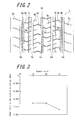
FIG. 2 is a partial development view of a tread pattern of the heavy load tire illustrated inFIG. 1 ; and -
FIG. 3 is a graph illustrating a relation between an aspect ratio and shear force in the braking direction in a heavy load tire according to the present disclosure. - An exemplary embodiment of a heavy load tire according to the present disclosure will be described below with reference to the drawings.
- A
heavy load tire 10 of the embodiment illustrated inFIG. 1 is used preferably in trucks and buses. Theheavy load tire 10 includes a pair of bead portions 1 and acarcass 2 composed of at least one carcass ply extending toroidally between the pair of bead portions 1. In a crown region of thecarcass 2, theheavy load tire 10 also includes the first to thefourth belt layer 3a to 3d arranged in the stated order from the inner side to the outer side in the tire radial direction. Tread rubber is also located outward of the first to thefourth belt layer 3a to 3d in the tire radial direction. The crown region of the carcass, the first to thefourth belt layer 3a to 3d, and the tread rubber as a whole form atread portion 5, which constitutes a crown region of the tire. Theheavy load tire 10 further includes a reinforcingrubber layer 4 on both sides in the tire width direction. Each reinforcingrubber layer 4 is located inward of thesecond belt layer 3b in the tire radial direction and extends from a position that is outward of thefirst belt layer 3a in the tire width direction to, in the present embodiment, an outer end portion of a sidewall portion in the tire radial direction. - As illustrated in
FIG. 2 , thetread portion 5 has an outer surface that is formed with fivecircumferential grooves 6a to 6e extending in the tire circumferential direction,fine grooves fine grooves 8a to 8c extending in a zigzag form by being inclined at a small angle with respect to the tire width direction. Thefine groove 8a communicates with the threecircumferential grooves 6b to 6d that are located in the vicinity of a tire equatorial plane CL and with thefine grooves fine grooves fine grooves - The
circumferential grooves bumps bumps - However, a tread pattern formed on the outer surface of the
tread portion 5 in the present embodiment is not limited to the aforementioned configuration. - The first to the
fourth belt layer 3a to 3d illustrated inFIG. 1 are each formed of one or more cords that are covered with rubber. The cord of thefirst belt layer 3a extends in the tire circumferential direction. The cord of thesecond belt layer 3b extends to be inclined with respect to the tire circumferential direction. The cord of thethird belt layer 3c extends to be inclined at an angle of 30° or less with respect to the tire circumferential direction in a direction opposite to that of the cord of thesecond belt layer 3b. The cord of thefourth belt layer 3d extends to be inclined with respect to the tire circumferential direction. - When a cord extends in a wave form, the center line of amplitude of the cord is construed as the direction in which the cord extends.
- Herein, any of the belt layers that include the cords extending at relatively small angles with respect to the tire circumferential direction, such as, especially, the
first belt layer 3a, may be formed by helically winding a strip of one or more cords made of steel or like that are covered with rubber, around the outer circumferential side of thecarcass 2. - The third belt layer has a width w3 that is 80 % or more of the tread width w. The second and the third belt layer respectively have widths w2 and w3 , which satisfy the relation w2 < w3 .
- The following describes an advantageous effect of the
heavy load tire 10 according to the present embodiment. - Generally, a pneumatic tire has a tread portion whose radius is gradually decreased from the center to the shoulder portion. Such a radius difference causes a difference in rolling speed between the center portion and the shoulder portion during rotation of the tire, and shear force acting in the braking direction is generated in the shoulder portion because, in the shoulder portion, the rolling speed is slow relative to the travelling distance on a road surface. The generated shear force has often resulted in partial wear in the shoulder portion.
- In this regard, in the
heavy load tire 10 of the present embodiment, the cord of thethird belt layer 3c is configured to be inclined with respect to the tire circumferential direction in the direction opposite to the direction in which the cord of thesecond belt layer 3b is inclined. This configuration allows the cord of thesecond belt layer 3b to intersect with the cord of thethird belt layer 3c, thereby improving in-plane bending stiffness (that is, stiffness against bending of the layered belts in an in-plane direction). To enhance this action, the inclination angle of the cord of thethird belt layer 3c with respect to the tire circumferential direction is preferably set to be 10°or more. - Furthermore, the cord of the
third belt layer 3c is configured to be inclined at an angle of 30° or less with respect to the tire circumferential direction, and the width w3 of thethird belt layer 3c is set to be greater than the width w2 of thesecond belt layer 3b, and moreover, the width w3 is set to be 80 % or more of the tread width. The above configurations make it possible to secure out-of-plane bending stiffness (that is, stiffness against bending of the shoulder portion of the belt in the tire radial direction) even in the vicinity of thetread ends 5a and to mitigate shear force acting in the braking direction in the vicinity of thetread ends 5a by positioning flexural center further outward in the tire radial direction, that is, in the vicinity of thethird belt layer 3c in the present embodiment, even near thetread ends 5a. - As a result of these actions, the
heavy load tire 10 of the present embodiment reduces shoulder edge wear. - To further enhance the advantageous effect of reducing shoulder edge wear, the width w3 of the
third belt layer 3c is preferably set to be 90 % or more of the tread width so that the flexural centers in regions that are even closer to the tread ends are positioned outward in the tire radial direction, and the inclination of thethird belt layer 3c with respect to the tire circumferential direction is preferably set to be 25° or less. Furthermore, the inclination of the cord of thesecond belt layer 3b with respect to the circumferential direction is preferably set to be 55° or less. In the present embodiment, the width w2 of thesecond belt layer 3b is preferably set to be 100 % or less of the tread width. - Meanwhile, from the viewpoint of securing durability of the tire, the width w3 of the
third belt layer 3c is preferably set to be 105 % or less of the tread width. - The cord of the
first belt layer 3a extends in the tire circumferential direction. - In a state where the tire has been inflated with the inner pressure, especially at the time of rotation of the tire under load, the cord of the
first belt layer 3a is subject to tension and acts to prevent the tire from undergoing expansion and deformation. As a result, the shape of the tire is maintained. To enhance this action, the width w1 of thefirst belt layer 3a is set to be preferably 50 % or more, and more preferably 60 % or more, of the tread width. - Furthermore, from the viewpoint of improving breaking strength of the cord, the cord of the
first belt layer 3a preferably extends in a wave form. Similarly from the viewpoint of improving fracture resistance of the cord, a high elongation cord (for example, a cord having an elongation of 4. 5 to 5. 5 % upon rupture) is preferably used as the cord of thefirst belt layer 3a. - The cord of the
second belt layer 3b is configured to be inclined with respect to the tire circumferential direction. This configuration makes it possible to secure plunger durability (that is, durability against bump input) of the tire. To further improve plunger durability, the inclination angle of the cord of thesecond belt layer 3b with respect to the tire circumferential direction is preferably set to be greater than 45° and less than or equal to 55°, and the width w2 of the second belt layer is set to be preferably 70 % or more, and more preferably 85 % or more, of the tread width. Setting the width w2 of the second belt layer to be 70 % or more of the tread width also improves steering stability further. - In the
heavy load tire 10 of the present embodiment, thefourth belt layer 3d is located outward of thethird belt layer 3c in the tire radial direction, and thefourth belt layer 3d extends to be inclined with respect to the tire circumferential direction. The belt width w4 of thefourth belt layer 3d and the direction in which the cord of thefourth belt layer 3d extends may be determined unrestrictedly in accordance with an action to be enhanced. For example, thefourth belt layer 3d acts to further reduce shoulder edge wear and to improve steering stability. - From the viewpoints of further reducing shoulder edge wear by further improving in-plane shear stiffness and of improving steering stability by increasing side force, the cord of the
fourth belt layer 3d is preferably configured to be inclined with respect to the tire circumferential direction in the direction opposite to that of thethird belt layer 3c in a manner such that the cord of thethird belt layer 3c intersects with the cord of thefourth belt layer 3d. To further enhance these effects, the inclination angle of the cord of thefourth belt layer 3d with respect to the tire circumferential direction is set to be preferably 70° or less, and more preferably from 15° to 55°. Furthermore, the width w4 of thefourth belt layer 3d is set to be preferably 20 % or more, and more preferably 30 % or more, of the tread width w. - From the viewpoint of improving durability of end portions of the belt layers by preventing the end portions of the belt layers from overlapping with each other, the width w4 of the
fourth belt layer 3d is preferably set to be less than the width w1 of thefirst belt layer 3a, and the width w4 of thefourth belt layer 3d is set to be preferably 70 % or less (and more preferably 55 % or less) of the tread width w. - In the
heavy load tire 10 of the present embodiment, the width w1 of thefirst belt layer 3a is set to be less than the width w2 of thesecond belt layer 3b, and the reinforcingrubber layers 4 are located inward of thesecond belt layer 3b in the tire radial direction and each extend from the position that is adjacent to the corresponding outer side of thefirst belt layer 3a in the tire width direction toward the outer side in the tire width direction. That is to say, the width w1 of thefirst belt layer 3a is less than the width w2 of thesecond belt layer 3b, and the widths w1 to w3 of the first to the third belt layer satisfy the relation w1 < w2 < w3 . Thus, the further outward a belt layer is located in the tire radial direction, the greater the width of the belt layer. Consequently, as illustrated inFIG. 1 , the single reinforcingrubber layer 4 located inward of thesecond belt layer 3b on each of both ends of thefirst belt layer 3a being closest to thecarcass 2 in the tire width direction suffices to maintain the shapes of the belt layers. - In contrast, when, for example, the relations w1 > w2 and w3 > w2 apply, the reinforcing rubber layers need to be located inward of the first belt layer in the tire radial direction, each reinforcing rubber layer extending from the position that is adjacent to the corresponding outer side of the first belt layer in the tire width direction toward the outer side in the tire width direction. Besides, additional reinforcing rubber layers need to be located inward of the third belt layer in the tire radial direction, each reinforcing rubber layer extending from a position that is adjacent to the corresponding outer side of the second belt layer in the tire width direction toward the outer side in the tire width direction.
- Accordingly, by satisfying the relation w1 < w2 < w3 , the number of the reinforcing rubber layers required for maintaining the shapes of the belt layers is reduced, resulting in reduction in manufacturing cost of the tire.
- Additionally, as the cords used in the
second belt layer 3b and/or thethird belt layer 3c, steel cords are preferable from the perspective of strength. Although such a steel cord is not limited to a particular type, a cord that, when not being covered with rubber, has a relative elongation of, for example, 0.3 % to 2 % under tensile force equal to 10 % of a breaking load may be used. - The present embodiment is suitably used in a tire having an aspect ratio of 65 or less to reduce shoulder edge wear particularly effectively.
- Example tires and Comparative Example tires having a size of 355/50R22.5 with the specifications shown below were produced experimentally, and each test tire was subjected to examination of shoulder edge wear resistance, examination of plunger durability, examination of durability in end portions of belt layers, and examination of steering stability as described below.
- As illustrated in
FIGs. 1 and2 , Example tires 1 to 13 each include a pair of bead portions and a carcass extending toroidally between the pair of bead portions and also include, on an outer circumferential side of a crown region of the carcass, the first belt layer including a cord extending in the tire circumferential direction, the second belt layer including a cord extending to be inclined with respect to the tire circumferential direction, and the third belt layer including a cord extending to be inclined at an angle of 30° or less with respect to the tire circumferential direction in a direction opposite to that of the cord of the second belt layer. The first, the second, and the third belt layer are arranged in the stated order from the inner side to the outer side in the tire radial direction. The widths w2 and w3 of the second and the third belt layer satisfy the relation w2 <w3 . In each of the second and the third belt layer, a steel cord that, when not being covered with rubber, has a relative elongation of 0.46 % under tensile force equal to 10 % of a breaking load is used. - Example tires 1 and 3 to 13 each also include the fourth belt layer having the width w4 .
- The cord of the second belt layer included in each of Example tires 1 to 12 is configured to extend in a wave form in the tire circumferential direction. On the other hand, the cord of the second belt layer included in Example tire 13 is configured to extend in a straight line form in the tire circumferential direction.
- On the other hand, Comparative Example tire 1 has substantially the same configuration as that of Example tire 1 except for that the width w3 of the third belt layer is 74 % of the tread width w (the width w3 being 226 mm).
- Comparative Example 2 has substantially the same configuration as that of Example tire 1 except for that the cord of the third belt layer extends to be inclined at an angle of 52° with respect to the tire circumferential direction in a direction opposite to that of the cord of the first belt layer.
- Comparative Example tire 3 includes a pair of bead portions and a carcass extending toroidally between the pair of bead portions and also include, on an outer circumferential side of a crown region of the carcass, the first and the second belt layer each including a cord extending in the tire circumferential direction, the third belt layer including a cord extending to be inclined at an angle of 52° with respect to the tire circumferential direction, and the fourth belt layer including a cord extending to be inclined at an angle of 52° with respect to the tire circumferential direction in a direction opposite to that of the cord of the third belt layer. The first, the second, the third, and the fourth belt layer are arranged in the stated order from the inner side to the outer side in the tire radial direction. The widths w1 to w4 of the first to the fourth belt layer are respectively 74 % (226 mm), 74 % (226 mm), 95 % (290 mm), and 85 % (260 mm) of the tread width w (305 mm). Except for the above differences, Comparative Example tire 3 has the same configuration as that of Example tire 1.
- Table 1 shows the specifications of Example tires and Comparative Example tires mentioned above. Note that signs assigned to the inclination angles of the cords of the first to the fourth belt layer with respect to the tire circumferential direction shown in Table 1 basically represent, when plus, that the cords are inclined with respect to the tire circumferential direction in a direction same as that of the cord of the second belt layer, and represent, when minus, that the cords are inclined with respect to the tire circumferential direction in the direction opposite to that of the cord of the second belt layer. As for Comparative Example tire 3, however, the inclination angle of the cord of the third belt layer is defined as plus, and the signs shows that the cord of the third belt layer and the cord of the fourth belt layer are inclined in directions opposite to each other with respect to the tire circumferential direction.
- Each test tire was assembled with a rim having a rim size of 11.75 inches, inflated at 900 kPa, and applied with a load of 4000 kgf, and then, was subjected to the following examinations.
- Example tires 1 to 13 and Comparative Example tires 1 to 3 were each assembled to a steering axis of a vehicle, and the vehicle was driven on an actual public road for 100,000 km. Subsequently, shoulder edge wear resistance was evaluated by measuring, for each tire, a wear amount (that is, an amount of change in height in the tire radial direction, hereinafter the same) of a tread end portion and a wear amount (that is, an amount of change in depth of a shoulder main groove) of a center block, and by comparing respective inverses of differences between the wear amounts measured for the tires. The evaluation results are shown in Table 1 based on the evaluation result of Comparative Example tire 3 being 100. Larger numerical values represent better shoulder edge wear resistance.
- In accordance with the breaking energy test specified by JIS D 4230, for each of Example tires 1 to 11 and Comparative Example tires 1 to 3, the plunger was pressed against the tread portion, and then, pushing force of the plunger immediately before the tire broke down and a travelling distance were examined, and the product of both values examined was obtained. The examination results were indexed with the examination result of Comparative Example tire 3 being defined as 100 for relative evaluation. Table 1 shows results of the evaluation. Larger numerical values represent better plunger durability.
- Example tires 1 to 4 and 13 were each assembled to an outside drum-type tester and driven for 20,000 km. Subsequently, for each tire, the length of a crack occurring between an end of the second belt layer in the tire width direction and an end of the third belt layer in the tire width direction was measured, and then, durability in the end portions of the belt layers was evaluated by comparing the respective inverses of the lengths measured for the test tires. The evaluation results are shown in Table 1 based on the evaluation result of
Comparative Example tire 2 being 100. Larger numerical values represent better durability in the end portions of the belt layers. - Cornering power of each of Example tires 1 to 4 and 13 was measured by using a flat-belt cornering tester. The cornering power of
Example tire 2 was defined as 100 for relative evaluation of steering stability. Table 1 shows results of the evaluation. Larger numerical values represent better steering stability.[Table 1] Example tire 1 Example tire 2 Example tire 3 Example tire 4 Examples tire 5 Example tire 6 Example tire 7 Example tire 8 Example tire 9 Example tire 10 Example tire 11 Examples tire 12 Example tire 13 Comparative Example tire 1 Comparative Example tire 2 Comparative Example tire 3 First belt layer Inclination angle of cord (°) 0 0 0 0 0 0 0 0 0 0 0 0 0 0 0 0 w1 /w(%) 74 74 74 74 74 74 60 74 74 74 74 74 74 74 74 74 Second belt layer Inclination angle of cord (°) +50 +50 +50 +50 +16 +50 +50 +50 +50 +50 +50 +50 +50 +50 +50 0 w2 /w(%) 91 91 91 91 91 60 70 85 91 91 91 100 91 91 91 74 Third belt layer Inclination angle of cord (°) -16 -16 -16 -16 -16 -16 -16 -16 -16 -16 -30 -16 -16 -16 -52 +52 w3 /w(%) 95 95 95 95 95 95 80 90 100 105 95 105 95 74 95 95 Fourth belt layer Inclination angle of cord (°) +16 - +16 -16 +16 +16 +16 +16 +16 +16 +16 +16 +16 +16 +16 -52 w4 /w(%) 46 - 85 46 46 46 46 46 46 46 46 46 46 46 46 85 Shoulder edge wear resistance 129 118 132 118 130 108 108 114 131 131 115 130 129 90 90 100 Plunger Durability 108 105 110 108 90 104 106 106 109 108 106 108 107 111 100 Durability in end portions of belt layers 98 100 85 102 98 Steering stability 105 100 108 101 105 - It has been found from Table 1 that Example tires 1 to 13 exhibit improved shoulder edge wear resistance compared with Comparative Examples 1 to 3.
- Furthermore, Example tires 1 to 4, 7 to 11, and 13, in each of which the cord of the second belt layer is inclined at an angle that is greater than 45° with respect to the tire circumferential direction and which the width
w2 of the second belt layer is 70 % or more of the tread width, exhibit improved plunger durability compared withExample tires 5 and 6. - Moreover,
Example tires 1, 3, and 4, each of which includes the fourth belt layer, exhibit improved steering stability compared withExample tire 2 which does not include the fourth belt layer. - Besides, although each tire subjected to the aforementioned examinations had an aspect ratio of 50, the aspect ratio of Example tire 1 described above was varied to simulate shear force applied to the shoulder portion in the braking direction. The simulation results are shown in
FIG. 3 . Shoulder edge wear is less likely to occur as shear force acting in the braking direction is closer to zero. - As is clearly seen from
FIG. 3 , in the heavy load tire of the present embodiment, as the aspect ratio is decreased, shear force acting in the braking direction is closer to zero, and shoulder edge wear is further prevented. -
- 1: bead portion
- 2: carcass
- 3a to 3d: first to fourth belt layers
- 4: reinforcing rubber layer
- w1 to w4 : widths of first to fourth belt layers
- w: tread width
- 10: heavy load tire
Claims (6)
- A heavy load tire that includes a pair of bead portions and a carcass extending toroidally between the pair of bead portions, the heavy load tire, on an outer circumferential side of a crown region of the carcass, comprising:a first belt layer comprising a cord extending in a tire circumferential direction;a second belt layer comprising a cord extending to be inclined with respect to the tire circumferential direction; anda third belt layer comprising a cord extending to be inclined at an angle of 30° or less with respect to the tire circumferential direction in a direction opposite to that of the cord of the second belt layer, the first belt layer, the second belt layer, and the third belt layer being arranged in the stated order from an inner side to an outer side in a tire radial direction, whereinthe third belt layer has a width w3 that is 80 % or more of a tread width w, andthe second belt layer has a width w2 , the width w2 and the width w3 satisfying the relation w2 < w3 .
- The heavy load tire of claim 1, wherein the width w3 of the third belt layer is 90 % or more of the tread width w.
- The heavy load tire of claim 1 or 2, wherein the cord of the second belt layer is inclined at an angle of greater than 45° with respect to the tire circumferential direction.
- The heavy load tire of any one of claims 1 to 3, wherein the width w2 of the second belt layer is 70 % or more of the tread width w.
- The heavy load tire of any one of claims 1 to 4, further comprising:a fourth belt layer comprising a cord extending to be inclined with respect to the tire circumferential direction, the fourth layer being located outward of the third belt layer in the tire radial direction.
- The heavy load tire of any one of claims 1 to 5, further comprising:a reinforcing rubber layer located inward of the second belt layer in the tire radial direction, the reinforcing rubber layer extending from a position located outward of the first belt layer in a tire width direction toward an outer side in the tire width direction, whereinthe first belt layer has a width w1 that is less than the width w2 of the second belt layer.
Applications Claiming Priority (2)
| Application Number | Priority Date | Filing Date | Title |
|---|---|---|---|
| JP2013024528A JP5628946B2 (en) | 2013-02-12 | 2013-02-12 | Heavy duty tire |
| PCT/JP2014/000611 WO2014125794A1 (en) | 2013-02-12 | 2014-02-05 | Heavy duty tire |
Publications (3)
| Publication Number | Publication Date |
|---|---|
| EP2957435A1 true EP2957435A1 (en) | 2015-12-23 |
| EP2957435A4 EP2957435A4 (en) | 2016-09-28 |
| EP2957435B1 EP2957435B1 (en) | 2019-01-16 |
Family
ID=51353807
Family Applications (1)
| Application Number | Title | Priority Date | Filing Date |
|---|---|---|---|
| EP14751297.4A Not-in-force EP2957435B1 (en) | 2013-02-12 | 2014-02-05 | Heavy duty tire |
Country Status (5)
| Country | Link |
|---|---|
| US (1) | US10569602B2 (en) |
| EP (1) | EP2957435B1 (en) |
| JP (1) | JP5628946B2 (en) |
| CN (1) | CN104995039B (en) |
| WO (1) | WO2014125794A1 (en) |
Families Citing this family (8)
| Publication number | Priority date | Publication date | Assignee | Title |
|---|---|---|---|---|
| DE102014209423A1 (en) * | 2014-05-19 | 2015-11-19 | Continental Reifen Deutschland Gmbh | Vehicle tires |
| JP6317633B2 (en) * | 2014-06-20 | 2018-04-25 | 住友ゴム工業株式会社 | Airless tire |
| JP6848510B2 (en) * | 2017-02-20 | 2021-03-24 | 住友ゴム工業株式会社 | Pneumatic tires for heavy loads |
| CN109866555A (en) * | 2017-12-04 | 2019-06-11 | 正新橡胶工业股份有限公司 | A kind of tire of tyre surface optimization structure |
| CN110203020B (en) * | 2019-06-14 | 2021-11-09 | 青岛科技大学 | All-steel radial tire with 90-degree belt structure |
| JP7121695B2 (en) * | 2019-06-19 | 2022-08-18 | 株式会社ブリヂストン | tire |
| CN110626124B (en) * | 2019-10-31 | 2025-07-25 | 中策橡胶集团股份有限公司 | Heavy-duty radial tire with endless woven multi-layer winding belt structure |
| KR102521630B1 (en) * | 2021-01-04 | 2023-04-14 | 한국타이어앤테크놀로지 주식회사 | A heavy duty tire |
Family Cites Families (26)
| Publication number | Priority date | Publication date | Assignee | Title |
|---|---|---|---|---|
| US2225042A (en) * | 1937-10-08 | 1940-12-17 | Goodrich Co B F | Tire |
| GB1483053A (en) * | 1973-09-22 | 1977-08-17 | Dunlop Ltd | Pneumatic tyres |
| JPS59124408A (en) * | 1982-12-29 | 1984-07-18 | Bridgestone Corp | Pneumatic flat radial tire for heavy load and preparation thereof |
| JP2648940B2 (en) | 1988-09-27 | 1997-09-03 | 株式会社ブリヂストン | Pneumatic tire |
| JP3016622B2 (en) * | 1991-04-27 | 2000-03-06 | 株式会社ブリヂストン | Pneumatic radial tire |
| JPH06183206A (en) * | 1992-12-16 | 1994-07-05 | Sumitomo Rubber Ind Ltd | Pneumatic tire |
| JPH07125507A (en) * | 1993-11-02 | 1995-05-16 | Bridgestone Corp | Radial tire for heavy load |
| JPH07164818A (en) * | 1993-12-16 | 1995-06-27 | Bridgestone Corp | Pneumatic radial tire |
| FR2754769B1 (en) * | 1996-10-23 | 1998-12-11 | Michelin & Cie | SUMMIT FRAME FOR TIRE-HEAVY TIRE WITH SHAPE RATIO <0.60 |
| JP4073081B2 (en) * | 1998-05-08 | 2008-04-09 | 株式会社ブリヂストン | Pneumatic radial tire |
| FR2778367B1 (en) * | 1998-05-11 | 2000-06-16 | Michelin & Cie | TIRE WITH TRIANGULAR TOP FRAME |
| US6708747B1 (en) | 1998-08-19 | 2004-03-23 | Bridgestone Corporation | Pneumatic radial tires |
| JP4190059B2 (en) * | 1998-08-19 | 2008-12-03 | 株式会社ブリヂストン | Pneumatic radial tire |
| JP2000062441A (en) * | 1998-08-25 | 2000-02-29 | Denso Corp | Vehicle air conditioner |
| US6561241B2 (en) * | 2001-04-23 | 2003-05-13 | The Goodyear Tire & Rubber Company | Two piece tire with improved tire tread belt and carcass |
| JP4046502B2 (en) | 2001-11-20 | 2008-02-13 | 株式会社ブリヂストン | Pneumatic radial tire |
| US7404425B2 (en) * | 2002-04-24 | 2008-07-29 | The Goodyear Tire & Rubber Company | Belt package for super single truck tires |
| BRPI0412723B1 (en) | 2003-07-18 | 2013-12-24 | Michelin Rech Tech | RADIAL HOUSING PNEUMATIC |
| JP4478104B2 (en) * | 2005-12-26 | 2010-06-09 | 住友ゴム工業株式会社 | Heavy duty tire |
| JP5087269B2 (en) * | 2006-12-22 | 2012-12-05 | 株式会社ブリヂストン | Pneumatic radial tire |
| JP4220569B1 (en) | 2007-11-05 | 2009-02-04 | 住友ゴム工業株式会社 | Pneumatic tire |
| JP5330820B2 (en) * | 2008-12-16 | 2013-10-30 | 株式会社ブリヂストン | Pneumatic tire |
| US9168789B2 (en) * | 2008-12-19 | 2015-10-27 | The Goodyear Tire & Rubber Company | Truck tire |
| JP2011162023A (en) | 2010-02-08 | 2011-08-25 | Bridgestone Corp | Pneumatic tire |
| FR2966384A1 (en) * | 2010-10-22 | 2012-04-27 | Michelin Soc Tech | PNEUMATIC COMPRISING A BUFFER ZONE BETWEEN THE CARCASE FRAME AND THE TOP FRAME |
| DE102011054975A1 (en) * | 2011-11-01 | 2013-05-02 | Continental Reifen Deutschland Gmbh | Vehicle tires |
-
2013
- 2013-02-12 JP JP2013024528A patent/JP5628946B2/en not_active Expired - Fee Related
-
2014
- 2014-02-05 CN CN201480008272.4A patent/CN104995039B/en not_active Expired - Fee Related
- 2014-02-05 US US14/763,682 patent/US10569602B2/en active Active
- 2014-02-05 EP EP14751297.4A patent/EP2957435B1/en not_active Not-in-force
- 2014-02-05 WO PCT/JP2014/000611 patent/WO2014125794A1/en not_active Ceased
Also Published As
| Publication number | Publication date |
|---|---|
| US20150352901A1 (en) | 2015-12-10 |
| CN104995039B (en) | 2017-07-11 |
| JP2014151818A (en) | 2014-08-25 |
| JP5628946B2 (en) | 2014-11-19 |
| WO2014125794A1 (en) | 2014-08-21 |
| EP2957435B1 (en) | 2019-01-16 |
| EP2957435A4 (en) | 2016-09-28 |
| US10569602B2 (en) | 2020-02-25 |
| CN104995039A (en) | 2015-10-21 |
Similar Documents
| Publication | Publication Date | Title |
|---|---|---|
| EP2957435B1 (en) | Heavy duty tire | |
| EP2781373B1 (en) | Pneumatic tire | |
| EP3205515B1 (en) | Pneumatic radial tire for passenger vehicle | |
| EP2628612B1 (en) | Pneumatic tire | |
| US9108472B2 (en) | Pneumatic heavy-duty tire having circumferential reinforcing layer and sipes | |
| US9415637B2 (en) | Pneumatic tire | |
| CN103813913B (en) | Pneumatic tire | |
| CN103764411B (en) | Pneumatic tire | |
| EP2982518B1 (en) | Pneumatic tire | |
| US9789732B2 (en) | Heavy load tire | |
| CN103813911A (en) | Pneumatic tire | |
| WO2014073285A1 (en) | Pneumatic tire | |
| EP3176009B1 (en) | Pneumatic tyre | |
| EP3332991B1 (en) | Pneumatic tire | |
| EP2979900A1 (en) | Heavy duty pneumatic tire | |
| EP3381719B1 (en) | Pneumatic tire | |
| EP3213929A1 (en) | Pneumatic tire for passenger cars | |
| EP1712377A1 (en) | Pneumatic tire | |
| JP7124494B2 (en) | Pneumatic tire and pneumatic tire manufacturing method | |
| US11633988B2 (en) | Pneumatic tire | |
| JP7323789B2 (en) | pneumatic tire | |
| JP7323790B2 (en) | pneumatic tire | |
| EP2248682A1 (en) | Studless tire |
Legal Events
| Date | Code | Title | Description |
|---|---|---|---|
| PUAI | Public reference made under article 153(3) epc to a published international application that has entered the european phase |
Free format text: ORIGINAL CODE: 0009012 |
|
| 17P | Request for examination filed |
Effective date: 20150731 |
|
| AK | Designated contracting states |
Kind code of ref document: A1 Designated state(s): AL AT BE BG CH CY CZ DE DK EE ES FI FR GB GR HR HU IE IS IT LI LT LU LV MC MK MT NL NO PL PT RO RS SE SI SK SM TR |
|
| AX | Request for extension of the european patent |
Extension state: BA ME |
|
| DAX | Request for extension of the european patent (deleted) | ||
| A4 | Supplementary search report drawn up and despatched |
Effective date: 20160831 |
|
| RIC1 | Information provided on ipc code assigned before grant |
Ipc: B60C 9/28 20060101ALI20160825BHEP Ipc: B60C 9/22 20060101ALI20160825BHEP Ipc: B60C 9/20 20060101AFI20160825BHEP |
|
| REG | Reference to a national code |
Ref country code: DE Ref legal event code: R079 Ref document number: 602014040022 Country of ref document: DE Free format text: PREVIOUS MAIN CLASS: B60C0009180000 Ipc: B60C0009200000 |
|
| GRAP | Despatch of communication of intention to grant a patent |
Free format text: ORIGINAL CODE: EPIDOSNIGR1 |
|
| STAA | Information on the status of an ep patent application or granted ep patent |
Free format text: STATUS: GRANT OF PATENT IS INTENDED |
|
| RIC1 | Information provided on ipc code assigned before grant |
Ipc: B60C 9/22 20060101ALI20180801BHEP Ipc: B60C 9/20 20060101AFI20180801BHEP Ipc: B60C 9/28 20060101ALI20180801BHEP |
|
| INTG | Intention to grant announced |
Effective date: 20180824 |
|
| GRAS | Grant fee paid |
Free format text: ORIGINAL CODE: EPIDOSNIGR3 |
|
| GRAA | (expected) grant |
Free format text: ORIGINAL CODE: 0009210 |
|
| STAA | Information on the status of an ep patent application or granted ep patent |
Free format text: STATUS: THE PATENT HAS BEEN GRANTED |
|
| AK | Designated contracting states |
Kind code of ref document: B1 Designated state(s): AL AT BE BG CH CY CZ DE DK EE ES FI FR GB GR HR HU IE IS IT LI LT LU LV MC MK MT NL NO PL PT RO RS SE SI SK SM TR |
|
| REG | Reference to a national code |
Ref country code: GB Ref legal event code: FG4D |
|
| REG | Reference to a national code |
Ref country code: CH Ref legal event code: EP |
|
| REG | Reference to a national code |
Ref country code: IE Ref legal event code: FG4D |
|
| REG | Reference to a national code |
Ref country code: DE Ref legal event code: R096 Ref document number: 602014040022 Country of ref document: DE |
|
| REG | Reference to a national code |
Ref country code: AT Ref legal event code: REF Ref document number: 1089438 Country of ref document: AT Kind code of ref document: T Effective date: 20190215 |
|
| REG | Reference to a national code |
Ref country code: NL Ref legal event code: MP Effective date: 20190116 |
|
| REG | Reference to a national code |
Ref country code: LT Ref legal event code: MG4D |
|
| PG25 | Lapsed in a contracting state [announced via postgrant information from national office to epo] |
Ref country code: NL Free format text: LAPSE BECAUSE OF FAILURE TO SUBMIT A TRANSLATION OF THE DESCRIPTION OR TO PAY THE FEE WITHIN THE PRESCRIBED TIME-LIMIT Effective date: 20190116 |
|
| REG | Reference to a national code |
Ref country code: AT Ref legal event code: MK05 Ref document number: 1089438 Country of ref document: AT Kind code of ref document: T Effective date: 20190116 |
|
| PG25 | Lapsed in a contracting state [announced via postgrant information from national office to epo] |
Ref country code: SE Free format text: LAPSE BECAUSE OF FAILURE TO SUBMIT A TRANSLATION OF THE DESCRIPTION OR TO PAY THE FEE WITHIN THE PRESCRIBED TIME-LIMIT Effective date: 20190116 Ref country code: PL Free format text: LAPSE BECAUSE OF FAILURE TO SUBMIT A TRANSLATION OF THE DESCRIPTION OR TO PAY THE FEE WITHIN THE PRESCRIBED TIME-LIMIT Effective date: 20190116 Ref country code: NO Free format text: LAPSE BECAUSE OF FAILURE TO SUBMIT A TRANSLATION OF THE DESCRIPTION OR TO PAY THE FEE WITHIN THE PRESCRIBED TIME-LIMIT Effective date: 20190416 Ref country code: PT Free format text: LAPSE BECAUSE OF FAILURE TO SUBMIT A TRANSLATION OF THE DESCRIPTION OR TO PAY THE FEE WITHIN THE PRESCRIBED TIME-LIMIT Effective date: 20190516 Ref country code: FI Free format text: LAPSE BECAUSE OF FAILURE TO SUBMIT A TRANSLATION OF THE DESCRIPTION OR TO PAY THE FEE WITHIN THE PRESCRIBED TIME-LIMIT Effective date: 20190116 Ref country code: ES Free format text: LAPSE BECAUSE OF FAILURE TO SUBMIT A TRANSLATION OF THE DESCRIPTION OR TO PAY THE FEE WITHIN THE PRESCRIBED TIME-LIMIT Effective date: 20190116 Ref country code: LT Free format text: LAPSE BECAUSE OF FAILURE TO SUBMIT A TRANSLATION OF THE DESCRIPTION OR TO PAY THE FEE WITHIN THE PRESCRIBED TIME-LIMIT Effective date: 20190116 |
|
| PG25 | Lapsed in a contracting state [announced via postgrant information from national office to epo] |
Ref country code: IS Free format text: LAPSE BECAUSE OF FAILURE TO SUBMIT A TRANSLATION OF THE DESCRIPTION OR TO PAY THE FEE WITHIN THE PRESCRIBED TIME-LIMIT Effective date: 20190516 Ref country code: RS Free format text: LAPSE BECAUSE OF FAILURE TO SUBMIT A TRANSLATION OF THE DESCRIPTION OR TO PAY THE FEE WITHIN THE PRESCRIBED TIME-LIMIT Effective date: 20190116 Ref country code: LV Free format text: LAPSE BECAUSE OF FAILURE TO SUBMIT A TRANSLATION OF THE DESCRIPTION OR TO PAY THE FEE WITHIN THE PRESCRIBED TIME-LIMIT Effective date: 20190116 Ref country code: HR Free format text: LAPSE BECAUSE OF FAILURE TO SUBMIT A TRANSLATION OF THE DESCRIPTION OR TO PAY THE FEE WITHIN THE PRESCRIBED TIME-LIMIT Effective date: 20190116 Ref country code: GR Free format text: LAPSE BECAUSE OF FAILURE TO SUBMIT A TRANSLATION OF THE DESCRIPTION OR TO PAY THE FEE WITHIN THE PRESCRIBED TIME-LIMIT Effective date: 20190417 Ref country code: BG Free format text: LAPSE BECAUSE OF FAILURE TO SUBMIT A TRANSLATION OF THE DESCRIPTION OR TO PAY THE FEE WITHIN THE PRESCRIBED TIME-LIMIT Effective date: 20190416 |
|
| REG | Reference to a national code |
Ref country code: CH Ref legal event code: PL |
|
| REG | Reference to a national code |
Ref country code: DE Ref legal event code: R097 Ref document number: 602014040022 Country of ref document: DE |
|
| PG25 | Lapsed in a contracting state [announced via postgrant information from national office to epo] |
Ref country code: LU Free format text: LAPSE BECAUSE OF NON-PAYMENT OF DUE FEES Effective date: 20190205 Ref country code: AL Free format text: LAPSE BECAUSE OF FAILURE TO SUBMIT A TRANSLATION OF THE DESCRIPTION OR TO PAY THE FEE WITHIN THE PRESCRIBED TIME-LIMIT Effective date: 20190116 Ref country code: CZ Free format text: LAPSE BECAUSE OF FAILURE TO SUBMIT A TRANSLATION OF THE DESCRIPTION OR TO PAY THE FEE WITHIN THE PRESCRIBED TIME-LIMIT Effective date: 20190116 Ref country code: RO Free format text: LAPSE BECAUSE OF FAILURE TO SUBMIT A TRANSLATION OF THE DESCRIPTION OR TO PAY THE FEE WITHIN THE PRESCRIBED TIME-LIMIT Effective date: 20190116 Ref country code: DK Free format text: LAPSE BECAUSE OF FAILURE TO SUBMIT A TRANSLATION OF THE DESCRIPTION OR TO PAY THE FEE WITHIN THE PRESCRIBED TIME-LIMIT Effective date: 20190116 Ref country code: IT Free format text: LAPSE BECAUSE OF FAILURE TO SUBMIT A TRANSLATION OF THE DESCRIPTION OR TO PAY THE FEE WITHIN THE PRESCRIBED TIME-LIMIT Effective date: 20190116 Ref country code: AT Free format text: LAPSE BECAUSE OF FAILURE TO SUBMIT A TRANSLATION OF THE DESCRIPTION OR TO PAY THE FEE WITHIN THE PRESCRIBED TIME-LIMIT Effective date: 20190116 Ref country code: EE Free format text: LAPSE BECAUSE OF FAILURE TO SUBMIT A TRANSLATION OF THE DESCRIPTION OR TO PAY THE FEE WITHIN THE PRESCRIBED TIME-LIMIT Effective date: 20190116 Ref country code: SK Free format text: LAPSE BECAUSE OF FAILURE TO SUBMIT A TRANSLATION OF THE DESCRIPTION OR TO PAY THE FEE WITHIN THE PRESCRIBED TIME-LIMIT Effective date: 20190116 Ref country code: MC Free format text: LAPSE BECAUSE OF FAILURE TO SUBMIT A TRANSLATION OF THE DESCRIPTION OR TO PAY THE FEE WITHIN THE PRESCRIBED TIME-LIMIT Effective date: 20190116 |
|
| REG | Reference to a national code |
Ref country code: BE Ref legal event code: MM Effective date: 20190228 |
|
| PLBE | No opposition filed within time limit |
Free format text: ORIGINAL CODE: 0009261 |
|
| STAA | Information on the status of an ep patent application or granted ep patent |
Free format text: STATUS: NO OPPOSITION FILED WITHIN TIME LIMIT |
|
| REG | Reference to a national code |
Ref country code: IE Ref legal event code: MM4A |
|
| PG25 | Lapsed in a contracting state [announced via postgrant information from national office to epo] |
Ref country code: SM Free format text: LAPSE BECAUSE OF FAILURE TO SUBMIT A TRANSLATION OF THE DESCRIPTION OR TO PAY THE FEE WITHIN THE PRESCRIBED TIME-LIMIT Effective date: 20190116 |
|
| 26N | No opposition filed |
Effective date: 20191017 |
|
| GBPC | Gb: european patent ceased through non-payment of renewal fee |
Effective date: 20190416 |
|
| PG25 | Lapsed in a contracting state [announced via postgrant information from national office to epo] |
Ref country code: CH Free format text: LAPSE BECAUSE OF NON-PAYMENT OF DUE FEES Effective date: 20190228 Ref country code: LI Free format text: LAPSE BECAUSE OF NON-PAYMENT OF DUE FEES Effective date: 20190228 |
|
| PG25 | Lapsed in a contracting state [announced via postgrant information from national office to epo] |
Ref country code: IE Free format text: LAPSE BECAUSE OF NON-PAYMENT OF DUE FEES Effective date: 20190205 Ref country code: GB Free format text: LAPSE BECAUSE OF NON-PAYMENT OF DUE FEES Effective date: 20190416 |
|
| PG25 | Lapsed in a contracting state [announced via postgrant information from national office to epo] |
Ref country code: SI Free format text: LAPSE BECAUSE OF FAILURE TO SUBMIT A TRANSLATION OF THE DESCRIPTION OR TO PAY THE FEE WITHIN THE PRESCRIBED TIME-LIMIT Effective date: 20190116 Ref country code: BE Free format text: LAPSE BECAUSE OF NON-PAYMENT OF DUE FEES Effective date: 20190228 |
|
| PG25 | Lapsed in a contracting state [announced via postgrant information from national office to epo] |
Ref country code: TR Free format text: LAPSE BECAUSE OF FAILURE TO SUBMIT A TRANSLATION OF THE DESCRIPTION OR TO PAY THE FEE WITHIN THE PRESCRIBED TIME-LIMIT Effective date: 20190116 |
|
| PG25 | Lapsed in a contracting state [announced via postgrant information from national office to epo] |
Ref country code: MT Free format text: LAPSE BECAUSE OF NON-PAYMENT OF DUE FEES Effective date: 20190205 |
|
| PG25 | Lapsed in a contracting state [announced via postgrant information from national office to epo] |
Ref country code: CY Free format text: LAPSE BECAUSE OF FAILURE TO SUBMIT A TRANSLATION OF THE DESCRIPTION OR TO PAY THE FEE WITHIN THE PRESCRIBED TIME-LIMIT Effective date: 20190116 |
|
| PG25 | Lapsed in a contracting state [announced via postgrant information from national office to epo] |
Ref country code: HU Free format text: LAPSE BECAUSE OF FAILURE TO SUBMIT A TRANSLATION OF THE DESCRIPTION OR TO PAY THE FEE WITHIN THE PRESCRIBED TIME-LIMIT; INVALID AB INITIO Effective date: 20140205 |
|
| PG25 | Lapsed in a contracting state [announced via postgrant information from national office to epo] |
Ref country code: MK Free format text: LAPSE BECAUSE OF FAILURE TO SUBMIT A TRANSLATION OF THE DESCRIPTION OR TO PAY THE FEE WITHIN THE PRESCRIBED TIME-LIMIT Effective date: 20190116 |
|
| P01 | Opt-out of the competence of the unified patent court (upc) registered |
Effective date: 20230531 |
|
| PGFP | Annual fee paid to national office [announced via postgrant information from national office to epo] |
Ref country code: DE Payment date: 20240219 Year of fee payment: 11 |
|
| PGFP | Annual fee paid to national office [announced via postgrant information from national office to epo] |
Ref country code: FR Payment date: 20240221 Year of fee payment: 11 |
|
| REG | Reference to a national code |
Ref country code: DE Ref legal event code: R119 Ref document number: 602014040022 Country of ref document: DE |
|
| PG25 | Lapsed in a contracting state [announced via postgrant information from national office to epo] |
Ref country code: DE Free format text: LAPSE BECAUSE OF NON-PAYMENT OF DUE FEES Effective date: 20250902 |
|
| PG25 | Lapsed in a contracting state [announced via postgrant information from national office to epo] |
Ref country code: FR Free format text: LAPSE BECAUSE OF NON-PAYMENT OF DUE FEES Effective date: 20250228 |