EP2957269A1 - Process and apparatus for supply of particulate material to a particulate printing process - Google Patents
Process and apparatus for supply of particulate material to a particulate printing process Download PDFInfo
- Publication number
- EP2957269A1 EP2957269A1 EP14172729.7A EP14172729A EP2957269A1 EP 2957269 A1 EP2957269 A1 EP 2957269A1 EP 14172729 A EP14172729 A EP 14172729A EP 2957269 A1 EP2957269 A1 EP 2957269A1
- Authority
- EP
- European Patent Office
- Prior art keywords
- particulate material
- particulate
- hopper
- transfer device
- discharge zone
- Prior art date
- Legal status (The legal status is an assumption and is not a legal conclusion. Google has not performed a legal analysis and makes no representation as to the accuracy of the status listed.)
- Withdrawn
Links
Images

Classifications
-
- A—HUMAN NECESSITIES
- A61—MEDICAL OR VETERINARY SCIENCE; HYGIENE
- A61F—FILTERS IMPLANTABLE INTO BLOOD VESSELS; PROSTHESES; DEVICES PROVIDING PATENCY TO, OR PREVENTING COLLAPSING OF, TUBULAR STRUCTURES OF THE BODY, e.g. STENTS; ORTHOPAEDIC, NURSING OR CONTRACEPTIVE DEVICES; FOMENTATION; TREATMENT OR PROTECTION OF EYES OR EARS; BANDAGES, DRESSINGS OR ABSORBENT PADS; FIRST-AID KITS
- A61F13/00—Bandages or dressings; Absorbent pads
- A61F13/15—Absorbent pads, e.g. sanitary towels, swabs or tampons for external or internal application to the body; Supporting or fastening means therefor; Tampon applicators
- A61F13/53—Absorbent pads, e.g. sanitary towels, swabs or tampons for external or internal application to the body; Supporting or fastening means therefor; Tampon applicators characterised by the absorbing medium
- A61F13/531—Absorbent pads, e.g. sanitary towels, swabs or tampons for external or internal application to the body; Supporting or fastening means therefor; Tampon applicators characterised by the absorbing medium having a homogeneous composition through the thickness of the pad
- A61F13/532—Absorbent pads, e.g. sanitary towels, swabs or tampons for external or internal application to the body; Supporting or fastening means therefor; Tampon applicators characterised by the absorbing medium having a homogeneous composition through the thickness of the pad inhomogeneous in the plane of the pad
- A61F13/5323—Absorbent pads, e.g. sanitary towels, swabs or tampons for external or internal application to the body; Supporting or fastening means therefor; Tampon applicators characterised by the absorbing medium having a homogeneous composition through the thickness of the pad inhomogeneous in the plane of the pad having absorbent material located in discrete regions, e.g. pockets
-
- A—HUMAN NECESSITIES
- A61—MEDICAL OR VETERINARY SCIENCE; HYGIENE
- A61F—FILTERS IMPLANTABLE INTO BLOOD VESSELS; PROSTHESES; DEVICES PROVIDING PATENCY TO, OR PREVENTING COLLAPSING OF, TUBULAR STRUCTURES OF THE BODY, e.g. STENTS; ORTHOPAEDIC, NURSING OR CONTRACEPTIVE DEVICES; FOMENTATION; TREATMENT OR PROTECTION OF EYES OR EARS; BANDAGES, DRESSINGS OR ABSORBENT PADS; FIRST-AID KITS
- A61F13/00—Bandages or dressings; Absorbent pads
- A61F13/15—Absorbent pads, e.g. sanitary towels, swabs or tampons for external or internal application to the body; Supporting or fastening means therefor; Tampon applicators
- A61F13/15577—Apparatus or processes for manufacturing
- A61F13/15617—Making absorbent pads from fibres or pulverulent material with or without treatment of the fibres
- A61F13/15658—Forming continuous, e.g. composite, fibrous webs, e.g. involving the application of pulverulent material on parts thereof
-
- B—PERFORMING OPERATIONS; TRANSPORTING
- B05—SPRAYING OR ATOMISING IN GENERAL; APPLYING FLUENT MATERIALS TO SURFACES, IN GENERAL
- B05C—APPARATUS FOR APPLYING FLUENT MATERIALS TO SURFACES, IN GENERAL
- B05C19/00—Apparatus specially adapted for applying particulate materials to surfaces
- B05C19/06—Storage, supply or control of the application of particulate material; Recovery of excess particulate material
-
- B—PERFORMING OPERATIONS; TRANSPORTING
- B65—CONVEYING; PACKING; STORING; HANDLING THIN OR FILAMENTARY MATERIAL
- B65G—TRANSPORT OR STORAGE DEVICES, e.g. CONVEYORS FOR LOADING OR TIPPING, SHOP CONVEYOR SYSTEMS OR PNEUMATIC TUBE CONVEYORS
- B65G65/00—Loading or unloading
- B65G65/30—Methods or devices for filling or emptying bunkers, hoppers, tanks, or like containers, of interest apart from their use in particular chemical or physical processes or their application in particular machines, e.g. not covered by a single other subclass
- B65G65/34—Emptying devices
- B65G65/40—Devices for emptying otherwise than from the top
- B65G65/48—Devices for emptying otherwise than from the top using other rotating means, e.g. rotating pressure sluices in pneumatic systems
- B65G65/4881—Devices for emptying otherwise than from the top using other rotating means, e.g. rotating pressure sluices in pneumatic systems rotating about a substantially horizontal axis
-
- A—HUMAN NECESSITIES
- A61—MEDICAL OR VETERINARY SCIENCE; HYGIENE
- A61F—FILTERS IMPLANTABLE INTO BLOOD VESSELS; PROSTHESES; DEVICES PROVIDING PATENCY TO, OR PREVENTING COLLAPSING OF, TUBULAR STRUCTURES OF THE BODY, e.g. STENTS; ORTHOPAEDIC, NURSING OR CONTRACEPTIVE DEVICES; FOMENTATION; TREATMENT OR PROTECTION OF EYES OR EARS; BANDAGES, DRESSINGS OR ABSORBENT PADS; FIRST-AID KITS
- A61F13/00—Bandages or dressings; Absorbent pads
- A61F13/15—Absorbent pads, e.g. sanitary towels, swabs or tampons for external or internal application to the body; Supporting or fastening means therefor; Tampon applicators
- A61F13/15577—Apparatus or processes for manufacturing
- A61F2013/15821—Apparatus or processes for manufacturing characterized by the apparatus for manufacturing
Definitions
- the present invention relates to a process and apparatus for supplying a particulate material to a particulate printing process, in particular at high process speeds.
- the present invention is particularly applicable to processes and apparatus for laying down predetermined patterns of superabsorbent particulates in order to form an absorbent core suitable for use in absorbent articles such as diapers, infant training pants, incontinence products, feminine hygiene products, sanitary napkins, for example.
- Composite structures comprising particulate material are well known in the art.
- Composite structures typically comprise an absorbent core for an absorbent product which has an absorbent particulate material that is immobilized when wet.
- the absorbent core comprises a substrate layer with an absorbent material, such as an absorbent polymer material.
- EP-A-1 621 165 published February 1st 2006 , discloses a process for producing absorbent structures.
- the process comprises a step of pre-metering an amount of particulate material by means of a transfer device having recesses on the surface which, in number, size and position, determine the pattern of particulate material taken up by the transfer device; moving the transfer device between a loading position and a meeting position; and expelling the particulate material onto a carrier layer at the meeting position so that a profiled distribution of particulate material is retained on the carrier layer.
- a transfer device having recesses on the surface which, in number, size and position, determine the pattern of particulate material taken up by the transfer device; moving the transfer device between a loading position and a meeting position; and expelling the particulate material onto a carrier layer at the meeting position so that a profiled distribution of particulate material is retained on the carrier layer.
- the present invention relates to a process for depositing particulate material in a predetermined pattern onto a moving surface comprising the steps of:
- the present invention further relates to an apparatus comprising:
- the present invention provides a profiled distribution of a particulate material which is accurate and reproducible even at high process speeds.
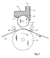
- FIG 1 shows a hopper (10) filled with a bulk of particulate material (12).
- the hopper (10) has a supply opening (14) on the upper side and a delivery opening (16) at the bottom.
- the hopper forms one embodiment of what is called “bulk” in the present context.
- a printing roll (18) enters into the opening (16) in the hopper (10) in a way that the bottom of the hopper surrounding the opening (16) closely follows the contour of the roller (18) and an unintended loss of particulate material is prevented.
- the printing roll (18) is provided with holes or recesses (22) on the surface thereof which are filled with particulate material (12) from the discharge zone (20) of the bulk of particulate (12) in the hopper (10), while the surface of the roll (18) passes through the particulate material (12) inside the hopper (10).
- the number, the size and the position of the recesses (22) are selected such that the volume and the pattern of the recesses correspond to the intended pattern and distribution profile of the particulate material which is to be received by the printing roll and to be transferred to a carrier layer as will be explained below.
- the printing roll (18) forms one embodiment of a transfer device according to the present invention.
- Another embodiment could for instance be formed by a belt having recesses in the surface thereof for receiving particulate material.
- Alternative methods of transferring the particulate material to the carrier layer may comprise air assisted transfer, transfer by centrifugal forces or electrical charge, for example.
- a rotatable printing roll is however a preferred embodiment as described in more detail, below.
- the particulate material is taken up by the recesses (22) of the printing roll (18) when one or more of the recesses (22) on the transfer roll (18) are in this loading position.
- the absorbent material is retained in these recesses on the way from the hopper (10) to a position called the deposition zone, where the printing roll (18) which is rotated in counter clockwise direction in Fig. 1 is in a position immediately adjacent the surface of a carrier layer (24).
- the carrier layer (24) is supported by a rotating support roll (25).
- the carrier layer is, for instance, a web material onto which the absorbent material are deposited or laid down (by gravity) from the printing roll.
- glue is applied, preferably slot-coated or sprayed, onto the carrier layer (24) upstream of the deposition zone between the printing roll (18) and the carrier layer (24), which upstream position is designated by reference numeral (26). Because the glue is applied in this upstream position (26) onto the carrier layer (24), the particulate material is retained on the carrier layer (24).
- Particularly preferred glue for retaining the absorbent material on the carrier layer (24) is a hot melt adhesive material applied through nozzles such as are commercially available from Nordson Company, Dawsonville, Georgia, USA.
- the support roll (25) which could alternatively also be provided by a moving belt, is also holding the absorbent material down onto the carrier, especially by use of a pressure differential (vacuum) through a screen forming the cylindrical surface of the support roll (25).
- glue is, optionally, sprayed onto the particulate material on the carrier layer (24).
- the glue is a microfilament glue entering like fibers between the granules of the particulate material to hold the whole deposit together.
- the cylindrical support roll surface may be advantageous to use materials for the cylindrical support roll surface, which have a low or no tendency to accumulate adhesive residue. This may be achieved by topological surface modification of surfaces (for instance at nano-scale), by ceramic coatings, or by a combination of both, e.g. Teflon TM coated surfaces or if a belt instead of a support roll is used, silicon rubber materials.
- the surface of the support roll can be made of a silicon rubber screen (preferably metal reinforced).
- gas is supplied under pressure to the bulk of particulate material within the hopper discharge zone.
- the gas assists the filling of the recesses.
- Figure 2 shows an enlarged view of the hopper (10) and the printing roll (18).
- Supply conduit (50) supplies gas (52) under pressure to the bulk of particulate material within the hopper discharge zone.
- the gas brings the particulate material to an expanded state and improves powder flowability in the hopper discharge zone.
- the gas is air, but other gasses could equally well be used. In the present invention this is referred to as air-assisted filling of the particulate material.
- the gas (52) is supplied under pressure within the bulk of particulate material within the hopper (10).
- a conduit (50) e.g. a pipe, carries the gas through the wall of the hopper (10) and into the bulk of the particulate material, and the gas (52) exits the conduit (50) through suitable holes, e.g. nozzles, located within the bulk of particulate material.
- the feed rate of the particulate material varies across the width of the opening (16) in the machine direction (i.e. in the direction tangential to the rotation of the printing roll (18) at the opening (16)). In some areas across the width of the opening, the flow rate of particulate material may be reduced to very low rates, or even to zero ("stagnation"). This can lead to inaccurate and inconsistent filling of the recesses in the printing roll (18) especially at high process speeds. It is believed that the introduction of the air-assisted filling gas (52) improves powder flowability which, in turn, causes more even flow rates of particulate material right across the width of the opening (16).
- Scraping means (32) may be provided at the edge of the bottom of the hopper as shown in Fig. 2 .
- the carrier layer is a web material.
- web material refers to an essentially endless material in one direction, i.e. the longitudinal extension, or the length, or the x-direction in Cartesian coordinates relative to the web material. Included in this term is an essentially unlimited sequence of pieces cut or otherwise separated from an essentially endless material.
- the web materials will have a thickness dimension (i.e. the z-direction) which is significantly smaller than the longitudinal extension (i.e. in x-direction).
- the width of web materials (the y-direction) will be significantly larger than the thickness, but less than the length.
- the thickness and the width of such materials is essentially constant along the length of the web.
- such web materials may be cellulosic fiber materials, tissues, woven or non-woven materials and the like.
- web materials are supplied in roll form, or on spools, or in a folded state in boxes. The individual deliveries may then be spliced together to form the essentially endless structure.
- a web material may be composed of several web materials, such as multilayer non-woven, coated tissues, non-woven/film laminates. Web materials may comprise other materials, such as added binding material, particles, hydrophilizing agents and the like.
- the particulate material preferably comprises absorbent gelling material.
- absorbent gelling material or “AGM”, “super absorbent material” or “SAM”, “superabsorbent”, “absorbent polymer material” are used herein interchangeably, and refer to polymeric material that can absorb at least 10 times (and typically at least 15 times, or at least 20 times) their weight of an aqueous 0.9% saline solution as measured using the Centrifuge Retention Capacity test (Edana 441.2-02)., i.e. having a CRC of at least 10 g/g, and typically at least 15 g/g or at least 20 g/g.
- Absorbent gelling material may be blended with other components, such as pulp fibres or "fluff”, but preferably absorbent gelling materials alone are fed in the process of the present invention through the hopper.
- the particulate material (12) may be held in the recesses (22) by means of a vacuum applied to the inner side of the transfer device (18), in combination with suction holes in (the bottom) of the recesses (22), to apply the vacuum suction to the particulate material.
- the vacuum is preferably released just before or at the deposition zone, e.g. the point where the transfer device (18) is adjacent to the carrier layer (24).
- the vacuum (60) may be any vacuum pressure such as for example at least 4 kPa, preferably at least 10 kPa, or even at least 20 kPa. A practical upper limit of 25 kPa vacuum is foressen, although vacuum in excess of this value are not excluded.
- the vacuum (60) may be provided by providing a plurality of vacuum chambers in the transfer device (18) (e.g. in its interior), where vacuum can be applied or released (connected or disconnected), depending on the position thereof in the process, e.g. when the vacuum chamber reaches the deposition zone, the vacuum may be disconnected and the particulate material (12) can flow from the transfer device (18) to the carrier layer (24), whilst when the chamber reaches the meeting point where the particulate material (12) flows from the feeder (10) to the recesses (22), the vacuum is applied (connected).
- the rate of gas input is approximately balanced with the rate of gas withdrawn through the print roll by the vacuum.
- Additional air pressure may be applied to the particulate material (12) close to or at the deposition zone, to ensure that the material flows from the reservoir (22) to the carrier layer (24).
- a three dimensional plate is employed to maintain the particulate material (12) within the recesses (22) while the particulate material (12) is being transferred.
- the plate is positioned adjacent to the feeder (10), downstream from the meeting point/area, and is positioned adjacent to, and in close proximity to, the transfer device (18).
- the feeder (10) is positioned before the plate, in direction of the process, e.g. in the direction of movement of the transfer device (18) (i.e. machine direction).
- the transfer device (18) i.e. machine direction
- the hopper (10) is vibrated, for example by means of an electro-magnetic vibrator connected to the wall of the hopper (10). Vibration of the hopper (10), in some circumstances, and especially at higher process speeds, further helps to improve filling of the recesses.
- the vibration frequency is from 10-500 Hz, more preferably from 30-70 Hz, and most preferably about 50 Hz.
- the bulk of the particulate material may be vibrated by an internal vibrator.
- the process speed may be conveniently defined by reference to the linear speed of the carrier layer (24).
- the linear speed of the carrier layer (24) corresponds approximately to the tangential speed of the printing roll (18) as the printing roll (18) and the carrier layer (24) are approximately, but not necessarily exactly, matched for speed at the deposition zone.
- the linear speed of the carrier layer (24) is at least 4.5 m/s, or at least 6 m/s, or at least 8 m/s, or at least 10 m/s.
- Such process speeds enable absorbent articles, or components thereof, to be manufactured at the rate of at least 1000, or at least 1200, or at least 1400 parts per minute, or higher.
Landscapes
- Health & Medical Sciences (AREA)
- Engineering & Computer Science (AREA)
- Vascular Medicine (AREA)
- Epidemiology (AREA)
- Biomedical Technology (AREA)
- Heart & Thoracic Surgery (AREA)
- Life Sciences & Earth Sciences (AREA)
- Animal Behavior & Ethology (AREA)
- General Health & Medical Sciences (AREA)
- Public Health (AREA)
- Veterinary Medicine (AREA)
- Manufacturing & Machinery (AREA)
- Mechanical Engineering (AREA)
- Absorbent Articles And Supports Therefor (AREA)
- Printing Methods (AREA)
Abstract
feeding the particulate material under gravity from a hopper to a discharge zone containing an feed opening;
supplying a gas under pressure to the bulk of particulate material within the hopper discharge zone;
transferring the particulate material through the feed opening to the surface of a transfer device, wherein the outer surface of the transfer device contains a pattern of particulate-receiving recesses;
rotating the transfer device to a deposition zone and transferring the particulate material to a carrier layer.
a hopper comprising a discharge zone, the discharge zone comprising a feed opening, and
wherein the discharge zone further comprises a gas supply assembly to supply gas under pressure into particulate material within the discharge zone;
a transfer device adjacent to the feed opening, wherein the outer surface of the transfer device contains a pattern of particulate-receiving recesses.
Description
- The present invention relates to a process and apparatus for supplying a particulate material to a particulate printing process, in particular at high process speeds. The present invention is particularly applicable to processes and apparatus for laying down predetermined patterns of superabsorbent particulates in order to form an absorbent core suitable for use in absorbent articles such as diapers, infant training pants, incontinence products, feminine hygiene products, sanitary napkins, for example.
- Composite structures comprising particulate material are well known in the art. Composite structures typically comprise an absorbent core for an absorbent product which has an absorbent particulate material that is immobilized when wet. The absorbent core comprises a substrate layer with an absorbent material, such as an absorbent polymer material.
-
US 4,863,076, issued on September 5th 1989 , discloses an apparatus and method for feeding particulate material from an aerated hopper into a process stream at a controlled flow rate. Whilst the flow rate of particulate material is controlled, this process is not capable of delivering a profiled distribution of the particulate material into the subsequent stage of the process. -
EP-A-1 621 165, published February 1st 2006 , discloses a process for producing absorbent structures. The process comprises a step of pre-metering an amount of particulate material by means of a transfer device having recesses on the surface which, in number, size and position, determine the pattern of particulate material taken up by the transfer device; moving the transfer device between a loading position and a meeting position; and expelling the particulate material onto a carrier layer at the meeting position so that a profiled distribution of particulate material is retained on the carrier layer. However, at ever-increasing process speeds, reliable and consistent transfer of the particulate material from the hopper into the recesses of the transfer device becomes difficult. In this case the recesses may not be consistently filled to the same level each and every time they are filled below the hopper and the accuracy and reproducibility of the profiled distribution on the carrier layer may be compromised. - There remains a need for a process and apparatus to accurately and reproducibly provide a profiled distribution of a particulate material, in particular and absorbent particulate material, to a carrier layer, even in a high speed process.
- The present invention relates to a process for depositing particulate material in a predetermined pattern onto a moving surface comprising the steps of:
- feeding the particulate material under gravity from a hopper to a discharge zone containing an feed opening;
- supplying a gas under pressure to the bulk of particulate material within the hopper discharge zone;
- transferring the particulate material through the feed opening to the surface of a transfer device, wherein the outer surface of the transfer device contains a pattern of particulate-receiving recesses;
- rotating the transfer device to a deposition zone and transferring the particulate material to a carrier layer.
- The present invention further relates to an apparatus comprising:
- a hopper comprising a discharge zone, the discharge zone comprising a feed opening, and
- wherein the discharge zone further comprises a gas supply assembly to supply gas under pressure into particulate material within the discharge zone;
- a transfer device adjacent to the feed opening, wherein the outer surface of the transfer device contains a pattern of particulate-receiving recesses.
-
- Figure 1
- illustrates one embodiment of the present invention;
- Figure 2
- is a diagrammatic illustration of the embodiment of
Figure 1 showing additional detail. - The present invention provides a profiled distribution of a particulate material which is accurate and reproducible even at high process speeds.
- Preferred embodiments of the present invention are explained below with reference to the Figures.
-
Figure 1 shows a hopper (10) filled with a bulk of particulate material (12). The hopper (10) has a supply opening (14) on the upper side and a delivery opening (16) at the bottom. The hopper forms one embodiment of what is called "bulk" in the present context. - A printing roll (18) enters into the opening (16) in the hopper (10) in a way that the bottom of the hopper surrounding the opening (16) closely follows the contour of the roller (18) and an unintended loss of particulate material is prevented.
- The printing roll (18) is provided with holes or recesses (22) on the surface thereof which are filled with particulate material (12) from the discharge zone (20) of the bulk of particulate (12) in the hopper (10), while the surface of the roll (18) passes through the particulate material (12) inside the hopper (10). The number, the size and the position of the recesses (22) are selected such that the volume and the pattern of the recesses correspond to the intended pattern and distribution profile of the particulate material which is to be received by the printing roll and to be transferred to a carrier layer as will be explained below.
- The printing roll (18) forms one embodiment of a transfer device according to the present invention. Another embodiment could for instance be formed by a belt having recesses in the surface thereof for receiving particulate material. Alternative methods of transferring the particulate material to the carrier layer may comprise air assisted transfer, transfer by centrifugal forces or electrical charge, for example. A rotatable printing roll is however a preferred embodiment as described in more detail, below.
- The particulate material is taken up by the recesses (22) of the printing roll (18) when one or more of the recesses (22) on the transfer roll (18) are in this loading position. The absorbent material is retained in these recesses on the way from the hopper (10) to a position called the deposition zone, where the printing roll (18) which is rotated in counter clockwise direction in
Fig. 1 is in a position immediately adjacent the surface of a carrier layer (24). The carrier layer (24) is supported by a rotating support roll (25). - The carrier layer is, for instance, a web material onto which the absorbent material are deposited or laid down (by gravity) from the printing roll. For holding the absorbent material on the carrier layer (24), glue is applied, preferably slot-coated or sprayed, onto the carrier layer (24) upstream of the deposition zone between the printing roll (18) and the carrier layer (24), which upstream position is designated by reference numeral (26). Because the glue is applied in this upstream position (26) onto the carrier layer (24), the particulate material is retained on the carrier layer (24). Particularly preferred glue for retaining the absorbent material on the carrier layer (24) is a hot melt adhesive material applied through nozzles such as are commercially available from Nordson Company, Dawsonville, Georgia, USA.
- It is preferred that the support roll (25), which could alternatively also be provided by a moving belt, is also holding the absorbent material down onto the carrier, especially by use of a pressure differential (vacuum) through a screen forming the cylindrical surface of the support roll (25). In another position downstream the transfer position between the printing roll (18) and the carrier layer (24), which position is designated by (28), glue is, optionally, sprayed onto the particulate material on the carrier layer (24). In a preferred embodiment the glue is a microfilament glue entering like fibers between the granules of the particulate material to hold the whole deposit together. In one embodiment it is also possible to apply a cover layer carrying glue onto the particulate material.
- It may be advantageous to use materials for the cylindrical support roll surface, which have a low or no tendency to accumulate adhesive residue. This may be achieved by topological surface modification of surfaces (for instance at nano-scale), by ceramic coatings, or by a combination of both, e.g. Teflon ™ coated surfaces or if a belt instead of a support roll is used, silicon rubber materials. Especially in case the carrier layer (24) is exposed to a vacuum on the inside of the support roll the surface of the support roll can be made of a silicon rubber screen (preferably metal reinforced).
- According to the present invention, gas is supplied under pressure to the bulk of particulate material within the hopper discharge zone. The gas assists the filling of the recesses.
-
Figure 2 shows an enlarged view of the hopper (10) and the printing roll (18). Supply conduit (50) supplies gas (52) under pressure to the bulk of particulate material within the hopper discharge zone. The gas brings the particulate material to an expanded state and improves powder flowability in the hopper discharge zone. Preferably the gas is air, but other gasses could equally well be used. In the present invention this is referred to as air-assisted filling of the particulate material. - In a preferred embodiment the gas (52) is supplied under pressure within the bulk of particulate material within the hopper (10). In this context it is meant that a conduit (50), e.g. a pipe, carries the gas through the wall of the hopper (10) and into the bulk of the particulate material, and the gas (52) exits the conduit (50) through suitable holes, e.g. nozzles, located within the bulk of particulate material.
- Without being bound by theory it is believed that the feed rate of the particulate material varies across the width of the opening (16) in the machine direction (i.e. in the direction tangential to the rotation of the printing roll (18) at the opening (16)). In some areas across the width of the opening, the flow rate of particulate material may be reduced to very low rates, or even to zero ("stagnation"). This can lead to inaccurate and inconsistent filling of the recesses in the printing roll (18) especially at high process speeds. It is believed that the introduction of the air-assisted filling gas (52) improves powder flowability which, in turn, causes more even flow rates of particulate material right across the width of the opening (16).
- There is a certain risk that additional particulate material beyond those filling the recesses are carried out of the hopper between the surface of the printing roll (18) and adjacent edge of the bottom of the hopper. Scraping means (32) may be provided at the edge of the bottom of the hopper as shown in
Fig. 2 . - As used herein the following terms have the following meanings:
- "Absorbent article" refers to devices that absorb and contain liquid, and more specifically, refers to devices that are placed against or in proximity to the body of the wearer to absorb and contain the various exudates discharged from the body. Absorbent articles include but are not limited to diapers, adult incontinence briefs, training pants, diaper holders and liners, sanitary napkins and the like.
- "Diaper" refers to an absorbent article generally worn by infants and incontinent persons about the lower torso.
- "Disposable" is used herein to describe articles that are generally not intended to be laundered or otherwise restored or reused (i.e., they are intended to be discarded after a single use and, preferably, to be recycled, composted or otherwise disposed of in an environmentally compatible manner).
- "Comprise," "comprising," and "comprises" is an open ended term that specifies the presence of what follows e.g. a component but does not preclude the presents of other features, elements, steps or components known in the art, or disclosed herein.
- Preferably the carrier layer is a web material. The term "web material" refers to an essentially endless material in one direction, i.e. the longitudinal extension, or the length, or the x-direction in Cartesian coordinates relative to the web material. Included in this term is an essentially unlimited sequence of pieces cut or otherwise separated from an essentially endless material. Often, though not necessarily, the web materials will have a thickness dimension (i.e. the z-direction) which is significantly smaller than the longitudinal extension (i.e. in x-direction). Typically, the width of web materials (the y-direction) will be significantly larger than the thickness, but less than the length. Often, though not necessarily, the thickness and the width of such materials is essentially constant along the length of the web. Without intending any limitation, such web materials may be cellulosic fiber materials, tissues, woven or non-woven materials and the like. Typically, though not necessarily, web materials are supplied in roll form, or on spools, or in a folded state in boxes. The individual deliveries may then be spliced together to form the essentially endless structure. A web material may be composed of several web materials, such as multilayer non-woven, coated tissues, non-woven/film laminates. Web materials may comprise other materials, such as added binding material, particles, hydrophilizing agents and the like.
- In the present invention the particulate material preferably comprises absorbent gelling material. The terms "absorbent gelling material" or "AGM", "super absorbent material" or "SAM", "superabsorbent", "absorbent polymer material" are used herein interchangeably, and refer to polymeric material that can absorb at least 10 times (and typically at least 15 times, or at least 20 times) their weight of an aqueous 0.9% saline solution as measured using the Centrifuge Retention Capacity test (Edana 441.2-02)., i.e. having a CRC of at least 10 g/g, and typically at least 15 g/g or at least 20 g/g. Absorbent gelling material may be blended with other components, such as pulp fibres or "fluff", but preferably absorbent gelling materials alone are fed in the process of the present invention through the hopper.
- According to one embodiment of the present invention, the particulate material (12) may be held in the recesses (22) by means of a vacuum applied to the inner side of the transfer device (18), in combination with suction holes in (the bottom) of the recesses (22), to apply the vacuum suction to the particulate material. The vacuum is preferably released just before or at the deposition zone, e.g. the point where the transfer device (18) is adjacent to the carrier layer (24). The vacuum (60) may be any vacuum pressure such as for example at least 4 kPa, preferably at least 10 kPa, or even at least 20 kPa. A practical upper limit of 25 kPa vacuum is foressen, although vacuum in excess of this value are not excluded.
- The vacuum (60) may be provided by providing a plurality of vacuum chambers in the transfer device (18) (e.g. in its interior), where vacuum can be applied or released (connected or disconnected), depending on the position thereof in the process, e.g. when the vacuum chamber reaches the deposition zone, the vacuum may be disconnected and the particulate material (12) can flow from the transfer device (18) to the carrier layer (24), whilst when the chamber reaches the meeting point where the particulate material (12) flows from the feeder (10) to the recesses (22), the vacuum is applied (connected).
- Ideally the rate of gas input is approximately balanced with the rate of gas withdrawn through the print roll by the vacuum.
- Additional air pressure may be applied to the particulate material (12) close to or at the deposition zone, to ensure that the material flows from the reservoir (22) to the carrier layer (24).
- In another embodiment of the invention, a three dimensional plate is employed to maintain the particulate material (12) within the recesses (22) while the particulate material (12) is being transferred. The plate is positioned adjacent to the feeder (10), downstream from the meeting point/area, and is positioned adjacent to, and in close proximity to, the transfer device (18). Thus, the feeder (10) is positioned before the plate, in direction of the process, e.g. in the direction of movement of the transfer device (18) (i.e. machine direction). Thus, it should be understood that at least part of the particulate material (12) contacts the surface of the transfer device (18) prior to contacting the first surface area of the plate.
- Further details of the three dimensional plate are disclosed in
EP-A-2 329 803, published on July 8th 2011 , and incorporated herein by reference. - It is particularly preferred to combine both of the embodiments described above, namely the vacuum embodiment and the three-dimensional plate embodiment, in a single process/apparatus.
- In one embodiment of the present invention the hopper (10) is vibrated, for example by means of an electro-magnetic vibrator connected to the wall of the hopper (10). Vibration of the hopper (10), in some circumstances, and especially at higher process speeds, further helps to improve filling of the recesses. Preferably the vibration frequency is from 10-500 Hz, more preferably from 30-70 Hz, and most preferably about 50 Hz.
- In another embodiment the bulk of the particulate material may be vibrated by an internal vibrator.
- The process speed may be conveniently defined by reference to the linear speed of the carrier layer (24). Note that the linear speed of the carrier layer (24) corresponds approximately to the tangential speed of the printing roll (18) as the printing roll (18) and the carrier layer (24) are approximately, but not necessarily exactly, matched for speed at the deposition zone. Preferably the linear speed of the carrier layer (24) is at least 4.5 m/s, or at least 6 m/s, or at least 8 m/s, or at least 10 m/s. Such process speeds enable absorbent articles, or components thereof, to be manufactured at the rate of at least 1000, or at least 1200, or at least 1400 parts per minute, or higher.
- In trials, the process shown in
Figures 1 and2 and described above was operated with and without air-assisted filling. The trials were carried out at a process speed of 1400 parts per minute and a vacuum within the print roll of 20kPa. The average loading of AGM per absorbent article, without any air-assisted filling used, was 6.5 grams. The average loading of AGM per absorbent article with air-assisted filling was 8 grams.
Claims (15)
- A process for depositing particulate material (12) in a predetermined pattern onto a carrier layer (24) comprising the steps of:feeding the particulate material (12) under gravity from a hopper (10) to a discharge zone (20) containing an feed opening (16);supplying a gas (52) under pressure to the bulk of particulate material (12) within the hopper discharge zone (20);transferring the particulate material (12) through the feed opening (16) to the surface of a transfer device (18), wherein the outer surface of the transfer device (18) contains a pattern of particulate-receiving recesses (22);rotating the transfer device (18) to a deposition zone and transferring the particulate material (12) to a carrier layer (24).
- The process according to claim 1 wherein the gas (52) is supplied under pressure within the bulk of particulate material (12) within the hopper discharge zone (20).
- The process according to either of claims 1 or 2 wherein the gas (52) under pressure is air.
- The process according to any of claims 1 to 3 further comprising the step of retaining the particulate material (12) within the particulate-receiving recesses (22) by vacuum.
- The process of claim 4 wherein the vacuum is between 4kPa and 25kPa.
- The process according to any of claims 1 to 5 further comprising the step of retaining the particulate material (12) within the particulate-receiving recesses (22) by a plate adjacent to, and in close proximity to, the surface of the transfer device (18).
- The process according to any of claims 1 to 6 further comprising the step of vibrating the hopper (10) at a frequency of from 10 to 500Hz, preferably from 30 to 70Hz.
- The process according to any of claims 1 to 7 wherein the particulate material (12) is absorbent gelling material.
- An apparatus comprising:a hopper (10) comprising a discharge zone (20), the discharge zone (20) comprising a feed opening (16), and wherein the discharge zone (20) further comprises a gas supply assembly (50) to supply gas (52) under pressure into a bulk of particulate material (12) within the discharge zone (20);a transfer device (18) adjacent to the feed opening (16), wherein the outer surface of the transfer device (18) contains a pattern of particulate-receiving recesses (22).
- The apparatus of claim 9 wherein the gas supply assembly (50) comprises a conduit within the hopper discharge zone (20) to supply gas under pressure within the bulk of particulate material (12) therein.
- The apparatus of either of claims 9 or 10 the wherein the gas (52) under pressure is air.
- The apparatus of any of claims 9 to 11 further comprising a source of vacuum to the particulate-receiving recesses (22) to retain the particulate material (12) therein.
- The apparatus according to any of claims 9 to 12 further comprising a plate adjacent to, and in close proximity to, the surface of the transfer device (18), to retain the particulate material (12) within the particulate receiving recesses (22) of the transfer device (18).
- The apparatus according to any of claims 9 to 13 further comprising a vibrator.
- The apparatus according to claim 14 wherein the vibrator comprises an electro-magnetic vibrator connected to the wall of the hopper (10) to vibrate the hopper.
Priority Applications (5)
| Application Number | Priority Date | Filing Date | Title |
|---|---|---|---|
| EP14172729.7A EP2957269A1 (en) | 2014-06-17 | 2014-06-17 | Process and apparatus for supply of particulate material to a particulate printing process |
| CN201580032574.XA CN106456391A (en) | 2014-06-17 | 2015-06-12 | Process and apparatus for supply of particulate material to particulate printing process |
| PCT/US2015/035495 WO2015195473A2 (en) | 2014-06-17 | 2015-06-12 | Process and apparatus for supply of particulate material to a particulate printing process |
| JP2016571340A JP2017516600A (en) | 2014-06-17 | 2015-06-12 | Process and apparatus for supplying particulate material to a particle printing process |
| US14/740,315 US9914149B2 (en) | 2014-06-17 | 2015-06-16 | Process and apparatus for supply of particulate material to a particulate printing process |
Applications Claiming Priority (1)
| Application Number | Priority Date | Filing Date | Title |
|---|---|---|---|
| EP14172729.7A EP2957269A1 (en) | 2014-06-17 | 2014-06-17 | Process and apparatus for supply of particulate material to a particulate printing process |
Publications (1)
| Publication Number | Publication Date |
|---|---|
| EP2957269A1 true EP2957269A1 (en) | 2015-12-23 |
Family
ID=51167570
Family Applications (1)
| Application Number | Title | Priority Date | Filing Date |
|---|---|---|---|
| EP14172729.7A Withdrawn EP2957269A1 (en) | 2014-06-17 | 2014-06-17 | Process and apparatus for supply of particulate material to a particulate printing process |
Country Status (5)
| Country | Link |
|---|---|
| US (1) | US9914149B2 (en) |
| EP (1) | EP2957269A1 (en) |
| JP (1) | JP2017516600A (en) |
| CN (1) | CN106456391A (en) |
| WO (1) | WO2015195473A2 (en) |
Families Citing this family (8)
| Publication number | Priority date | Publication date | Assignee | Title |
|---|---|---|---|---|
| BR112018068096B1 (en) | 2016-03-31 | 2022-08-16 | Kimberly-Clark Worldwide, Inc | METHOD FOR FORMATION OF AN ABSORBENT CORE |
| KR102554740B1 (en) | 2016-03-31 | 2023-07-13 | 킴벌리-클라크 월드와이드, 인크. | Absorbent cores and methods for forming absorbent cores |
| US11141320B2 (en) | 2016-03-31 | 2021-10-12 | Kimberly-Clark Worldwide, Inc. | Absorbent cores and methods for forming absorbent cores |
| RU2698084C1 (en) | 2016-03-31 | 2019-08-21 | Кимберли-Кларк Ворлдвайд, Инк. | Absorbent cores and methods for forming absorbent cores |
| CN112691862A (en) * | 2020-03-09 | 2021-04-23 | 斯佩(新昌)科技有限公司 | Inflatable stretching dispersion type anti-counterfeiting particle printing method |
| CN115836013A (en) * | 2020-07-30 | 2023-03-21 | 宝洁公司 | Absorbent article packaging material with natural fibers |
| CN116261440B (en) | 2020-08-25 | 2026-02-13 | 金伯利-克拉克环球有限公司 | Absorption structures and methods for manufacturing absorption structures |
| CN121060761B (en) * | 2025-10-17 | 2026-01-27 | 江苏希诚新材料科技有限公司 | A coating apparatus and coating method for conductive pastes |
Citations (5)
| Publication number | Priority date | Publication date | Assignee | Title |
|---|---|---|---|---|
| US4863076A (en) | 1987-07-13 | 1989-09-05 | The Ohio State University | Particulate material feeder utilizing vibration and aeration |
| EP1621165A1 (en) | 2004-07-28 | 2006-02-01 | The Procter & Gamble Company | Indirect printing of AGM |
| WO2010103453A1 (en) * | 2009-03-09 | 2010-09-16 | Gdm S.P.A. | A unit for making absorbent nappy/diaper pads |
| EP2329803A1 (en) | 2009-12-02 | 2011-06-08 | The Procter & Gamble Company | Apparatus and method for transferring particulate material |
| EP2554144A1 (en) * | 2010-03-26 | 2013-02-06 | Uni-Charm Corporation | Apparatus and method for manufacturing absorbing body |
Family Cites Families (6)
| Publication number | Priority date | Publication date | Assignee | Title |
|---|---|---|---|---|
| DE3234431A1 (en) * | 1982-09-17 | 1984-03-22 | Roderich Wilhelm Dr.-Ing. 6100 Darmstadt Gräff | METHOD AND DEVICE FOR REMOVING GASES AND STEAMS FROM DRYING FUNNELS FILLED WITH BULK MATERIAL |
| US4604313A (en) * | 1984-04-23 | 1986-08-05 | Kimberly-Clark Corporation | Selective layering of superabsorbents in meltblown substrates |
| US5560878A (en) * | 1994-11-30 | 1996-10-01 | The Procter & Gamble Company | Method and apparatus for making stretchable absorbent articles |
| DE60325672D1 (en) * | 2002-06-10 | 2009-02-26 | Kao Corp | An absorbent core and method of making the same |
| US8148598B2 (en) * | 2006-02-22 | 2012-04-03 | Dsg Technology Holdings Limited | Method of making an absorbent composite and absorbent articles employing the same |
| US8206533B2 (en) * | 2008-08-26 | 2012-06-26 | The Procter & Gamble Company | Method and apparatus for making disposable absorbent article with absorbent particulate polymer material and article made therewith |
-
2014
- 2014-06-17 EP EP14172729.7A patent/EP2957269A1/en not_active Withdrawn
-
2015
- 2015-06-12 JP JP2016571340A patent/JP2017516600A/en not_active Ceased
- 2015-06-12 WO PCT/US2015/035495 patent/WO2015195473A2/en not_active Ceased
- 2015-06-12 CN CN201580032574.XA patent/CN106456391A/en active Pending
- 2015-06-16 US US14/740,315 patent/US9914149B2/en active Active
Patent Citations (6)
| Publication number | Priority date | Publication date | Assignee | Title |
|---|---|---|---|---|
| US4863076A (en) | 1987-07-13 | 1989-09-05 | The Ohio State University | Particulate material feeder utilizing vibration and aeration |
| EP1621165A1 (en) | 2004-07-28 | 2006-02-01 | The Procter & Gamble Company | Indirect printing of AGM |
| EP2292199A1 (en) * | 2004-07-28 | 2011-03-09 | The Procter & Gamble Company | Indirect printing of agm |
| WO2010103453A1 (en) * | 2009-03-09 | 2010-09-16 | Gdm S.P.A. | A unit for making absorbent nappy/diaper pads |
| EP2329803A1 (en) | 2009-12-02 | 2011-06-08 | The Procter & Gamble Company | Apparatus and method for transferring particulate material |
| EP2554144A1 (en) * | 2010-03-26 | 2013-02-06 | Uni-Charm Corporation | Apparatus and method for manufacturing absorbing body |
Also Published As
| Publication number | Publication date |
|---|---|
| WO2015195473A3 (en) | 2016-03-17 |
| WO2015195473A2 (en) | 2015-12-23 |
| JP2017516600A (en) | 2017-06-22 |
| US9914149B2 (en) | 2018-03-13 |
| US20150359683A1 (en) | 2015-12-17 |
| CN106456391A (en) | 2017-02-22 |
Similar Documents
| Publication | Publication Date | Title |
|---|---|---|
| US9914149B2 (en) | Process and apparatus for supply of particulate material to a particulate printing process | |
| AU2005269573B2 (en) | Indirect printing of AGM | |
| US11185451B2 (en) | Indirect printing of AGM | |
| RU2613159C2 (en) | Method and device for production of environmentally safe absorbing structure | |
| MX2007001002A (en) | Process for producing absorbent core structures. | |
| JP2002516191A (en) | Method and apparatus for forming an air-blown fiber absorbent core | |
| JP2013524942A (en) | Apparatus and method for receiving and moving solid materials | |
| US11464679B2 (en) | High speed SAP particle applicator | |
| KR20110127673A (en) | Units for making absorbent diaper pads | |
| WO2014188302A1 (en) | Machine and method for making absorbent sanitary articles | |
| GB2539668A (en) | Method for applying particles to a moving web and apparatus therefor | |
| HK1100635A (en) | Indirect printing of agm |
Legal Events
| Date | Code | Title | Description |
|---|---|---|---|
| PUAI | Public reference made under article 153(3) epc to a published international application that has entered the european phase |
Free format text: ORIGINAL CODE: 0009012 |
|
| AK | Designated contracting states |
Kind code of ref document: A1 Designated state(s): AL AT BE BG CH CY CZ DE DK EE ES FI FR GB GR HR HU IE IS IT LI LT LU LV MC MK MT NL NO PL PT RO RS SE SI SK SM TR |
|
| AX | Request for extension of the european patent |
Extension state: BA ME |
|
| 17P | Request for examination filed |
Effective date: 20160607 |
|
| RBV | Designated contracting states (corrected) |
Designated state(s): AL AT BE BG CH CY CZ DE DK EE ES FI FR GB GR HR HU IE IS IT LI LT LU LV MC MK MT NL NO PL PT RO RS SE SI SK SM TR |
|
| 17Q | First examination report despatched |
Effective date: 20170307 |
|
| STAA | Information on the status of an ep patent application or granted ep patent |
Free format text: STATUS: THE APPLICATION IS DEEMED TO BE WITHDRAWN |
|
| 18D | Application deemed to be withdrawn |
Effective date: 20190618 |