EP2957230A1 - Remote control for patient support system - Google Patents
Remote control for patient support system Download PDFInfo
- Publication number
- EP2957230A1 EP2957230A1 EP15170780.9A EP15170780A EP2957230A1 EP 2957230 A1 EP2957230 A1 EP 2957230A1 EP 15170780 A EP15170780 A EP 15170780A EP 2957230 A1 EP2957230 A1 EP 2957230A1
- Authority
- EP
- European Patent Office
- Prior art keywords
- control unit
- axis
- patient support
- support system
- oriented
- Prior art date
- Legal status (The legal status is an assumption and is not a legal conclusion. Google has not performed a legal analysis and makes no representation as to the accuracy of the status listed.)
- Granted
Links
Images




Classifications
-
- A—HUMAN NECESSITIES
- A61—MEDICAL OR VETERINARY SCIENCE; HYGIENE
- A61G—TRANSPORT, PERSONAL CONVEYANCES, OR ACCOMMODATION SPECIALLY ADAPTED FOR PATIENTS OR DISABLED PERSONS; OPERATING TABLES OR CHAIRS; CHAIRS FOR DENTISTRY; FUNERAL DEVICES
- A61G13/00—Operating tables; Auxiliary appliances therefor
- A61G13/02—Adjustable operating tables; Controls therefor
-
- A—HUMAN NECESSITIES
- A61—MEDICAL OR VETERINARY SCIENCE; HYGIENE
- A61B—DIAGNOSIS; SURGERY; IDENTIFICATION
- A61B6/00—Apparatus or devices for radiation diagnosis; Apparatus or devices for radiation diagnosis combined with radiation therapy equipment
- A61B6/04—Positioning of patients; Tiltable beds or the like
- A61B6/0407—Supports, e.g. tables or beds, for the body or parts of the body
-
- A—HUMAN NECESSITIES
- A61—MEDICAL OR VETERINARY SCIENCE; HYGIENE
- A61B—DIAGNOSIS; SURGERY; IDENTIFICATION
- A61B6/00—Apparatus or devices for radiation diagnosis; Apparatus or devices for radiation diagnosis combined with radiation therapy equipment
- A61B6/04—Positioning of patients; Tiltable beds or the like
- A61B6/0487—Motor-assisted positioning
-
- A—HUMAN NECESSITIES
- A61—MEDICAL OR VETERINARY SCIENCE; HYGIENE
- A61G—TRANSPORT, PERSONAL CONVEYANCES, OR ACCOMMODATION SPECIALLY ADAPTED FOR PATIENTS OR DISABLED PERSONS; OPERATING TABLES OR CHAIRS; CHAIRS FOR DENTISTRY; FUNERAL DEVICES
- A61G13/00—Operating tables; Auxiliary appliances therefor
- A61G13/02—Adjustable operating tables; Controls therefor
- A61G13/04—Adjustable operating tables; Controls therefor tiltable around transverse or longitudinal axis
-
- A—HUMAN NECESSITIES
- A61—MEDICAL OR VETERINARY SCIENCE; HYGIENE
- A61G—TRANSPORT, PERSONAL CONVEYANCES, OR ACCOMMODATION SPECIALLY ADAPTED FOR PATIENTS OR DISABLED PERSONS; OPERATING TABLES OR CHAIRS; CHAIRS FOR DENTISTRY; FUNERAL DEVICES
- A61G13/00—Operating tables; Auxiliary appliances therefor
- A61G13/02—Adjustable operating tables; Controls therefor
- A61G13/06—Adjustable operating tables; Controls therefor raising or lowering of the whole table surface
-
- A—HUMAN NECESSITIES
- A61—MEDICAL OR VETERINARY SCIENCE; HYGIENE
- A61N—ELECTROTHERAPY; MAGNETOTHERAPY; RADIATION THERAPY; ULTRASOUND THERAPY
- A61N5/00—Radiation therapy
- A61N5/10—X-ray therapy; Gamma-ray therapy; Particle-irradiation therapy
- A61N5/1048—Monitoring, verifying, controlling systems and methods
- A61N5/1049—Monitoring, verifying, controlling systems and methods for verifying the position of the patient with respect to the radiation beam
-
- A—HUMAN NECESSITIES
- A61—MEDICAL OR VETERINARY SCIENCE; HYGIENE
- A61G—TRANSPORT, PERSONAL CONVEYANCES, OR ACCOMMODATION SPECIALLY ADAPTED FOR PATIENTS OR DISABLED PERSONS; OPERATING TABLES OR CHAIRS; CHAIRS FOR DENTISTRY; FUNERAL DEVICES
- A61G2203/00—General characteristics of devices
- A61G2203/10—General characteristics of devices characterised by specific control means, e.g. for adjustment or steering
- A61G2203/12—Remote controls
-
- A—HUMAN NECESSITIES
- A61—MEDICAL OR VETERINARY SCIENCE; HYGIENE
- A61N—ELECTROTHERAPY; MAGNETOTHERAPY; RADIATION THERAPY; ULTRASOUND THERAPY
- A61N5/00—Radiation therapy
- A61N5/10—X-ray therapy; Gamma-ray therapy; Particle-irradiation therapy
- A61N5/1048—Monitoring, verifying, controlling systems and methods
- A61N5/1049—Monitoring, verifying, controlling systems and methods for verifying the position of the patient with respect to the radiation beam
- A61N2005/1051—Monitoring, verifying, controlling systems and methods for verifying the position of the patient with respect to the radiation beam using an active marker
Definitions
- This invention relates to a patient support system and, in particular, to a means for manipulating the patient support system.
- a patient support may be used in a medical environment to support a patient who is undergoing examination or a medical procedure, for example a radiotherapy procedure.
- a known patient support includes an upper surface upon which a patient can sit or lie while a procedure is carried out.
- the upper surface may be mounted upon a base and may include functionality to enable the upper surface of the support to be moved relative to the base of the support.
- a patient may need to be positioned so that a body portion, for example the left lung, is positioned over the centre of the base of the patient support. This may be achieved by translating the upper surface of the support to the right with respect to the base, so that the left lung of the patient is positioned centrally relative to the base of the support.
- a first aspect of the invention provides a patient support system, comprising a patient support having a base and an upper surface, the upper surface moveable relative to the base in a direction along at least one of a first axis, a second axis orthogonal to the first axis, and a third axis orthogonal to the first and second axes; and a control unit for controlling movement of the upper surface, the control unit defining a longitudinal axis; wherein the direction of movement of the upper surface relative to the base is determined by the orientation of the longitudinal axis of the control unit relative to the patient support.
- the upper surface When the control unit is oriented such that its longitudinal axis is parallel to or within a defined angular range of the first axis, the upper surface may be moveable along the first axis. When the control unit is oriented such that its longitudinal axis is parallel to or within a defined angular range of the second axis, the upper surface may be moveable along the second axis. When the control unit is oriented such that its longitudinal axis is parallel to or within a defined angular range of the third axis, the upper surface may be moveable along the third axis.
- control of the movement of the upper surface by the control unit may be prohibited.
- the upper surface may be moveable in a direction corresponding to a combination of movements along two or more of the first, second and third axes.
- the control unit is oriented such that its longitudinal axis has components in two or more of the first, second and third axes (and outside the defined angular ranges of those axes)
- the upper surface may be moveable in a direction having respective components along the two or more of the first, second and third axes.
- the defined angular range about each axis may be a range of 30 degrees.
- the control unit may comprise a first user interface for receiving a user input.
- the upper surface may be configured to move in response to a user input received via the first user interface.
- the first user interface may comprise a sliding input device, the sliding input device moveable along a track.
- the control unit may have a front end and a rear end.
- the sliding input device may be movable between a front end of the track and a rear end of the track, the front end and the rear end of the track corresponding to the front end and the rear end of the control unit respectively.
- the sliding input device may be biased towards a central position along the track.
- the direction of movement of the upper surface along the particular axis may correspond to a direction of movement of the sliding input device along the track.
- the upper surface may be rotationally moveable relative to the base about at least one of the first axis, the second axis, and the third axis.
- the control unit may further comprise a toggle switch, moveable between a first position and a second position.
- the toggle switch When the toggle switch is in the first position, the first user interface may be configured to effect linear movement of the upper surface and, when the toggle switch is in the second position, the first user interface may be configured to effect rotational movement of the upper surface.
- the upper surface When the control unit is oriented such that its longitudinal axis is parallel to or within the defined angular range of the first axis, the upper surface may be rotatable about one of first, second or third axes. When the control unit is oriented such that its longitudinal axis is parallel to or within the defined angular range of the second axis, the upper surface may be rotatable about another of the first, second or third axes. When the control unit is oriented such that its longitudinal axis is parallel to or within the defined angular range of the third axis, the upper surface may be rotatable about the other of the first, second or third axes.
- the sliding input device may be rotatable with respect to the control unit.
- the sliding input device may be configured such that rotating the sliding input device effects rotation of the upper surface relative to the base of the patient support.
- the control unit may include at least one transmitter and the patient support may include at least one receiver.
- the at least one transmitter may be configured to communicate with the at least one receiver in order for the orientation of the control unit relative to the patient support to be determined.
- the at least one transmitter may comprise an ultrasound transmitter, infrared transmitter and/or an RFID transmitter and the at least one receiver may comprise an ultrasound receiver, an infrared receiver and/or an RFID receiver.
- the control unit may comprise an inertial measurement device for determining one or more of the orientation and position of the control unit relative to the patient support.
- the inertial measurement device may comprise one or more of an accelerometer, a gyroscope, a compass and a magnetometer.
- the position and orientation of the control unit may be determined by one or more external sensors.
- the position and orientation of the patient support may be determined by one or more external sensors.
- the control unit may comprise an activation switch moveable between a first position and a second position, and biased towards the second position.
- an activation switch moveable between a first position and a second position, and biased towards the second position.
- Figure 1 shows a patient support system 100 that includes a patient support 102 having an upper surface 104 on which a patient can sit or lie down for examination or for treatment.
- the upper surface 104 is moveably mounted onto a base 106.
- the upper surface 104 may be moved relative to the base 106 by a mechanism (not shown) located between, or within one or more of, the upper surface and the base.
- the base 106 may also be moveable, for example along a surface, or adjustable, for example to increase or reduce the height of the upper surface 104 above the ground.
- Movement of the upper surface 104 relative to the base 106 is achieved using a control unit 200 which may be connected to the patient support 102 by a cable or wirelessly using a known wireless communication standard such as IEEE 802.11a, 802.11g, 802.11n, Bluetooth or RFID.
- the control unit 200 will be discussed in more detail with reference to Figures 2A and 2B .
- Figure 1B shows the possible directions of movement of the upper surface 104 relative to the base 106 and the possible rotational movements of the upper surface.
- Movement in the +z direction represents a linear movement of the upper surface 104 upwards, away from the base 106
- movement in the -z direction represents a linear movement of the upper surface downwards, towards the base.
- Movement in the +y direction represents a linear movement of the upper surface 104 in that direction relative to the base 106
- movement in the -y direction represents a linear movement of the upper surface in that direction relative to the base.
- movement in the +y and -y directions represent linear movement along a longitudinal axis of the patient support 102, and perpendicular to the x and z axes.
- Movement in the +x direction represents a linear movement of the upper surface 104 in that direction relative to the base 106
- movement in the -x direction represents a linear movement of the upper surface 104 in that direction relative to the base 106.
- movement in the +x and -x directions represents movement of the upper surface 104 in a direction perpendicular to the y and z axes.
- the base 106 may include a mechanism (not shown) to enable it to extend or retract in the +z or -z directions, along the z axis, for example to increase its height.
- movement of the upper surface 104 along the z axis may be achieved by extending or retracting the base along the z axis, while the upper surface 104 is not moved relative to the base.
- rotation of the upper surface relative to the base can also be effected.
- a rotation in the +a direction represents a rotational movement of the upper surface 104 about the x axis, so as to raise the head of a patient lying on the bed and to lower the feet of the patient.
- a movement in the -a direction represents a rotational movement of the upper surface 104 relative to the base 106 about the x axis so as to raise the feet of a patient lying on the upper surface and to lower the patient's head.
- Movement in the +b direction represents a rotational movement of the upper surface 104 relative to the base 106 about the y axis
- movement in the -b direction represents a rotational movement of the upper surface in a direction opposite to the +b direction.
- Movement in the +c direction represents a rotational movement of the upper surface 104 relative to the base 106 about the z axis
- movement in the -c direction represents a rotational movement of the upper surface about the z axis in a direction opposite to the +c direction.
- Rotation in the +a and -a directions about the x axis can be considered to adjust the pitch of the upper surface 104; rotation in the +b and -b direction about the y axis can be considered to adjust the roll of the upper surface; and rotation in the +c and -c directions about the z axis can be considered to adjust to yaw of the upper surface.
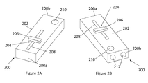
- Figures 2A and 2B show the control unit 200 from two different angles; Figure 2A shows a rear end 200a of the control unit in a perspective view, and Figure 2B shows a front end 200b of the control unit in a perspective view.
- the control unit 200 is a handheld unit intended to be held in one hand of an operator, such as technician or medical professional.
- the control unit 200 has a housing 202 which, in the embodiment shown, is generally rectangular cuboidal in shape. In other embodiments, however, the housing 202 may be formed in a more ergonomic shape, for example to fit comfortably into the hand of an operator.
- the control unit 200 has two interfaces via which a user can input commands.
- a first interface 204 is, in this embodiment, in the form of a slider switch which includes an actuator 206 moveable along a track 208.
- biasing means within the housing 202 act to urge the actuator 206 to a central position along the track 208 such that, when an operator removes his or her finger from the actuator, the actuator returns to its central position along the track, as shown in Figures 2A and 2B .
- An operator is able to slide the actuator 206 in either direction (that is, towards the rear end 200a or towards the front end 200b) along the track 208 in order to effect movement of the upper surface 104 of the patient support 102, as will be discussed with reference to Figures 3 to 7 .
- a second user interface 210 takes the form of a button which functions as a toggle switch.
- the button 210 enables an operator to toggle between linear movement and rotational movement. That is to say, when the button 210 is pressed, the first user interface is configured to effect rotational movement of the upper surface 104 (in directions +a, -a, +b, -b, +c and -c), and when the button is not pressed, the first user interface can be used to effect linear movement of the upper surface (in directions +x, -x, +y, -y, +z and -z).
- Use of the control unit 200 to effect movement of the upper surface 104 will be discussed in greater detail with reference to Figures 3 to 7 .
- the control unit 200 may include an indicator, such as a light (not shown), to indicate to an operator when the button 210 is depressed.
- an indicator such as a light (not shown) to indicate to an operator when the button 210 is depressed.
- the light may be illuminated when the button 210 is depressed and, therefore, causes the first user interface to effect rotational movement of the patient support 102.
- a pair of ultrasound emitters 212 are provided on the front end 200b of the control unit 200. In other embodiments, the ultrasound emitters 212 may be located elsewhere on the control unit 200.
- the ultrasound emitters 212 are configured to communicate with a pair of ultrasound receivers 214 (see Figure 1A ) located on the base 106 of the patient 102.
- the base 16 includes multiple pairs of ultrasound receivers 214 which are in communication with the ultrasound emitters 212.
- a single pair of ultrasound receivers 214 is shown located on an end of the base 106.
- the ultrasound receivers 214 may, in other embodiments, be located elsewhere on the patient support 102, for example on another surface of the base or on the upper surface 104.
- the purpose of the ultrasound emitters 212 and the ultrasound receivers 214 is to enable a determination to be made of the approximate location of the control unit 200 relative to the patient support 102 and of the orientation of the control unit relative to the patient support.
- the control unit 200 may additionally or alternatively include radio frequency identification (RFID) beacons or emitters, which can communicate with RFID trackers or receivers on the patient support 102, the base 106, or elsewhere near to the patient support, in order to determine the orientation of the control unit with respect to the base 106.
- RFID radio frequency identification
- control unit may include infrared emitters which can communicate with infrared receivers on the patient support 102, the base 106, or elsewhere near to the patient support, in order to determine the orientation of the control unit with respect to the base 106.
- control unit 200 may, in some embodiments, include one or more additional sensors such as an inertial measurement device (not shown) to enable a determination to be made of the orientation of the control unit 200 relative to the patient support 102.
- the inertial measurement device may comprise one or more of an accelerometer, a gyroscope, a compass and a magnetometer.
- At least one emitter/transmitter is configured to communicate with at least one receiver.
- an external sensor system may be used to track one or more of the orientation and position of the control unit 200, and one or more of the orientation and position of the patient support 102. The external sensor system may then compare the position and/or orientation of the control unit 200 relative to the position and/or orientation of the patient support 102, and thus determine the direction of movement of the upper surface 104 as controlled by the control unit 200 (for which, see below).
- control unit may be achieved using a wired or cable connection (not shown).
- emitters 212 and receivers 214 communicate with each other using ultrasound, in other embodiments, different communication modalities may be used.
- Figures 3A to 3D show, diagrammatically, how the upper surface 104 of the patent support 102 may be moved along the x and y axes.
- Figure 3A shows the upper surface 104 as viewed from above.
- the direction of linear movement of the upper surface 104 is determined by the orientation of the control unit 200 relative to the patient support 102.
- the control unit 200 is considered to define a longitudinal axis and, in order for the control unit to effect linear movement of the upper surface 104 one of the x or y axes, the control unit must be oriented such that its longitudinal axis is parallel to or substantially parallel to that axis along which movement is desired.
- control unit 200 For example, to enable the control unit 200 to be used to move the upper surface 104 along the y axis, the control unit must be held in such an orientation that its longitudinal axis is parallel to or substantially parallel to the y axis, as shown in Figure 3B .
- the control unit is considered to be oriented substantially parallel to a particular axis if it is oriented within a defined angular range of that axis, for example within a 30 degree range.
- the orientation of the control unit 200 relative to the upper surface 104 is determined by the communication between the ultrasound emitters 212 on the control unit and the ultrasound receivers 214 on the base 106 of the patient support 102.
- the time-of-flight of signals emitted from each of the emitters 212 and detected by each of the receivers 214 can be used to determine the distance of each emitter from each receiver. This information, combined with the known distances between the emitters 212 and between the receivers 214, allows the relative orientation of the control unit 200 with respect to the patient support 102 to be determined.
- the emitters and receivers in pairs it is possible to differentiate between the signals transmitted and received by each transmitter/receiver in a pair.
- the transmitters in a pair are positioned sufficiently far apart from one another that a determination can be made of how the transmitters are positioned relative to one another and, therefore, how the control unit 200 is oriented with respect to the patient support 102.
- the transmitters in a pair can communicate using different frequencies in order to be distinguished from each other, and thus determine how the control unit 200 is oriented with respect to the patient support 102.
- the orientation of the control unit 200 may additionally or alternatively be determined using one or more sensors, such as an inertial measurement device located within the housing 202 of the control unit, or RFID beacons located in the control unit and RFID trackers located on or near to the base.
- sensors such as an inertial measurement device located within the housing 202 of the control unit, or RFID beacons located in the control unit and RFID trackers located on or near to the base.
- a user With the control unit 200 oriented in the manner shown in Figure 3B (that is parallel to or substantially parallel to the y axis), a user is able to move the upper surface in the +y direction by sliding the actuator 206 along the track 208 in the +y direction (that is towards the front end 202b of the control unit), and is able to move the upper surface in the -y direction by sliding the actuator along the track in the -y direction (that is towards the rear end 202a of the control unit).
- control unit 200 is oriented parallel to the y axis, with the front end 202b of the control unit aimed in the +y direction. If the control unit is held facing the opposite direction, with the front end 202b of the control unit aimed in the -y direction, then the direction of movement effected by the actuator 206 is reversed; sliding the actuator along the track 208 towards the front end of the control unit will cause the upper surface 104 to move in the -y direction. Similarly, movement of the actuator 206 along the track 208 towards the rear end 202a of the control unit 200 will cause the upper surface 104 to move in the +y direction.
- the control unit 200 In order to move the upper surface 104 along the x axis, the control unit 200 must be oriented parallel to or substantially parallel to the x axis, as shown in Figure 3C .
- a user is able to move the upper surface 104 of the patient support 102 in the +x direction by sliding the actuator 206 along the track 208 in the +x direction (that is towards the front end 202b of the control unit) and is able to move the upper surface in the -x direction by sliding the actuator along the track in the -x direction (that is towards the rear end 202a of the control unit).
- control unit 200 is oriented parallel to the x axis, with the front end 202b of the control unit aimed in the +x direction. If the control unit is held facing the opposite direction, with the front end 202b of the control unit aimed in the -x direction, then the direction of movement effected by the actuator 206 is reversed; sliding the actuator along the track 208 towards the front end of the control unit will cause the upper surface 104 to move in the -x direction. Similarly, movement of the actuator 206 along the track 208 towards the rear end 202a of the control unit 200 will cause the upper surface 104 to move in the +x direction.
- control unit 200 is oriented parallel to or substantially parallel to an axis, then movement of the actuator 206 along the track 208 in a particular direction will cause the upper surface 104 to move in a corresponding direction along the axis.
- the patient support system 100 is configured, in one embodiment, such that the upper surface will not move if the control unit is not oriented parallel to or substantially parallel to the direction of movement.
- the controller 200 is oriented such that it is not parallel to or within a defined angular range of a direction of motion (that is, if the control unit is not oriented parallel to or within a defined angular range of the x or y axes), such as in Figure 3D , then sliding the actuator 206 along the track 208 will not cause any movement of the upper surface 104.
- the defined angular range may be +/- 30 degrees (that is, an arc of 30 degrees either side of the axis). Preferably, the angular range will be no less than +/- 10 degrees.
- Regions 300 in Figure 3A denote so called "dead zones". If the control unit 200 is oriented such that its longitudinal axis is parallel to an axis within a dead zone 300, then movement of the actuator 206 along the track 208 will have no effect on the position of the upper surface 104.
- the upper surface may be moveable in a direction corresponding to a combination of movements along two or more of the first, second and third axes.
- the control unit when the control unit is oriented such that its longitudinal axis has components in two or more of the first, second and third axes (and outside the defined angular ranges of those axes), the upper surface may be moveable in a direction having respective components along the two or more of the first, second and third axes.
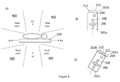
- Figures 4A to D show diagrammatically how the upper surface 104 of the patent support 102 may be moved along the y and z axes.
- Figure 4A shows the upper surface 104 as viewed from the side.
- the control unit 200 in order for the control unit 200 to effect linear movement of the upper surface 104 one of the y or z axes, the control unit must be oriented such that its longitudinal axis is parallel to or substantially parallel to that axis along which movement is desired. In other words, to enable the control unit 200 to be used to move the upper surface 104 along the z axis, the control unit must be held in an orientation parallel to or substantially parallel to the z axis, as shown in Figure 4B .
- a user With the control unit 200 oriented in the manner shown in Figure 4B (substantially parallel to the z axis), a user is able to move the upper surface in the +z direction by sliding the actuator 206 along the track 208 in the +z direction (that is towards the front end 202b of the control unit), and is able to move the upper surface in the -z direction by sliding the actuator along the track in the -z direction (that is towards the rear end 202a of the control unit).
- control unit 200 is oriented parallel to the z axis, with the front end 202b of the control unit aimed in the +z direction. If the control unit is held facing the opposite direction, with the front end 202b of the control unit aimed in the -z direction, then the direction of movement effected by the actuator 206 is effectively reversed; sliding the actuator along the track 208 towards the front end of the control unit will cause the upper surface 104 to move in the -z direction. Similarly, movement of the actuator 206 along the track 208 towards the rear end 202a of the control unit 200 will cause the upper surface 104 to move in the +z direction.
- Figures 5A and 5B show how the upper surface 104 of the patient support 102 may be rotated in the +c and -c directions, about the z axis.
- the upper surface 104 shown in plan view, is oriented with its longitudinal axis parallel to the y axis.
- the button 210 on the control unit 200 must be pressed which, effectively, puts the control unit into rotation mode.
- the actuator 206 can be used to rotate the upper surface 104 in the +c and -c directions.
- orienting the control unit 200 in the opposite way by aiming the front end 202b in the -y direction, does not change the functionality of the actuator 206; with the control unit 200 oriented in this way (that is with the front end 202b aimed in the -y direction), sliding the actuator in the -y direction (towards the front end of the control unit) will cause the upper surface 104 to rotate in the +c direction, and sliding the actuator in the +y direction (towards the rear end 202a of the control unit) will cause the upper surface to rotate in the -c direction.
- the actuator 206 is rotatable with respect to the control unit 200 and/or to the track 208.
- the actuator may be rotatable around its point of contact with the track 208. In some embodiments, this rotation may only be possible once the button 210 is depressed. In other embodiments, rotation may be possible when the button 210 is not depressed, but no rotation signal is transmitted unless the button is depressed. If the control unit is oriented substantially parallel with respect to the y axis, then rotating the actuator 206 in the +c direction will cause the upper surface 104 of the upper surface 104 of the patient support to rotate in the +c direction.
- Figures 6A and 6B show the upper surface 104 of the patient support 102 may be rotated in the +a and -a directions, about the x axis.
- the upper surface 104 shown in a side view, is oriented with its longitudinal axis parallel to the y axis.
- the actuator 206 can be used to rotate the upper surface 104 in the +a and -a directions.
- the control unit 200 oriented as shown in Figure 6B , along the z axis, and with the front end 202b aimed in the +z direction, then sliding the actuator in the +z direction (towards the front end of the control unit) causes the upper surface to rotate in the +a direction.
- orienting the control unit 200 in the opposite way does not change the functionality of the actuator 206; with the control unit 200 oriented in this way (that is with the front end 202b aimed in the -z direction), sliding the actuator in the -z direction (towards the front end of the control unit) will cause the upper surface 104 to rotate in the +a direction, and sliding the actuator in the +z direction (towards the rear end 202a of the control unit) will cause the upper surface to rotate in the -a direction.
- the actuator 206 is rotatable with respect to the control unit 200 and/or to the track 208. If the control unit is oriented substantially parallel with respect to the z axis, then rotating the actuator 206 in the +a direction will cause the upper surface 104 of the upper surface 104 of the patient support to rotate in the +a direction. Similarly, rotating the actuator in the -a direction will cause the upper surface 104 of the patient support to rotate in the -a direction.
- Figures 7A and 7B show how the upper surface 104 of the patient support 102 may be rotated in the +b and -b directions, about the y axis.
- the upper surface 104 shown in an end view, is oriented with its longitudinal axis parallel to the y axis.
- the actuator 206 can be used to rotate the upper surface 104 in the +b and -b directions.
- the control unit 200 oriented as shown in Figure 7B , along the x axis, and with the front end 202b aimed in the +x direction, then sliding the actuator in the +x direction (towards the front end of the control unit) causes the upper surface to rotate in the +b direction.
- orienting the control unit 200 in the opposite way does not change the functionality of the actuator 206; with the control unit 200 oriented in this way (that is with the front end 202b aimed in the -x direction), sliding the actuator in the -x direction (towards the front end of the control unit) will cause the upper surface 104 to rotate in the +b direction, and sliding the actuator in the +x direction (towards the rear end 202a of the control unit) will cause the upper surface to rotate in the -b direction.
- orienting the control unit 200 in a particular way with respect to the patient support 102 causes the upper surface 104 to move in a particular direction
- those directions may be reversed or varied.
- orienting the control unit 200 such that it is parallel to the y axis may cause movement of the upper surface 104 along the x or z axes.
- the actuator 206 is rotatable with respect to the control unit 200 and/or to the track 208. If the control unit is oriented substantially parallel with respect to the x axis, then rotating the actuator 206 in the +b direction will cause the upper surface 104 of the upper surface 104 of the patient support to rotate in the +b direction. Similarly, rotating the actuator in the -b direction will cause the upper surface 104 of the patient support to rotate in the -b direction.
- Figures 8A and 8B show a control unit 800 constructed in accordance with an alternative embodiment of the invention.
- Figure 8A is a side view of the control unit 800 which includes an actuator 802 and a button 804, which correspond to the actuator 206 and the button 210 of the control unit 200 of Figures 2A and 2B .
- the control unit 800 includes a spring-loaded switch 806 extending from a bottom wall 808 of a housing 810 of the control unit.
- the switch 806 functions as a "dead man's switch" so that functionality of the actuator 802 and the button 804 is only enabled if the switch 806 is pressed.
- the location of the switch 806 enables a user to press the switch with his or her finger while holding the control unit 800.
- a user holding the control unit 800 is able to press the switch 806 with his or her finger and, simultaneously, control the actuator 802 and the button 804 with his or her thumb.
- the switch 806 is spring-loaded such that, if the user removes his or her finger from the switch, for example if the user drops the control unit 800, and pressure on the switch is removed, then the switch rapidly opens, thereby preventing further movement of the upper surface 104 of the patient support 102.
Landscapes
- Health & Medical Sciences (AREA)
- Life Sciences & Earth Sciences (AREA)
- Engineering & Computer Science (AREA)
- Biomedical Technology (AREA)
- Animal Behavior & Ethology (AREA)
- General Health & Medical Sciences (AREA)
- Public Health (AREA)
- Veterinary Medicine (AREA)
- Medical Informatics (AREA)
- Radiology & Medical Imaging (AREA)
- Nuclear Medicine, Radiotherapy & Molecular Imaging (AREA)
- Pathology (AREA)
- High Energy & Nuclear Physics (AREA)
- Biophysics (AREA)
- Optics & Photonics (AREA)
- Physics & Mathematics (AREA)
- Heart & Thoracic Surgery (AREA)
- Molecular Biology (AREA)
- Surgery (AREA)
- Accommodation For Nursing Or Treatment Tables (AREA)
Abstract
Description
- This invention relates to a patient support system and, in particular, to a means for manipulating the patient support system.
- A patient support may be used in a medical environment to support a patient who is undergoing examination or a medical procedure, for example a radiotherapy procedure.
- A known patient support includes an upper surface upon which a patient can sit or lie while a procedure is carried out. The upper surface may be mounted upon a base and may include functionality to enable the upper surface of the support to be moved relative to the base of the support. For example, a patient may need to be positioned so that a body portion, for example the left lung, is positioned over the centre of the base of the patient support. This may be achieved by translating the upper surface of the support to the right with respect to the base, so that the left lung of the patient is positioned centrally relative to the base of the support.
- Existing control systems used for manipulating the position of a bed of a patient support or manipulating the position of the entire patient support can be complicated and the use of such control systems is often not intuitive. Thus, it can be difficult to move the patient into the required position.
- A first aspect of the invention provides a patient support system, comprising a patient support having a base and an upper surface, the upper surface moveable relative to the base in a direction along at least one of a first axis, a second axis orthogonal to the first axis, and a third axis orthogonal to the first and second axes; and a control unit for controlling movement of the upper surface, the control unit defining a longitudinal axis; wherein the direction of movement of the upper surface relative to the base is determined by the orientation of the longitudinal axis of the control unit relative to the patient support.
- When the control unit is oriented such that its longitudinal axis is parallel to or within a defined angular range of the first axis, the upper surface may be moveable along the first axis. When the control unit is oriented such that its longitudinal axis is parallel to or within a defined angular range of the second axis, the upper surface may be moveable along the second axis. When the control unit is oriented such that its longitudinal axis is parallel to or within a defined angular range of the third axis, the upper surface may be moveable along the third axis.
- When the control unit is oriented such that its longitudinal axis is outside the defined angular ranges, control of the movement of the upper surface by the control unit may be prohibited. Alternatively, when the control unit is oriented such that its longitudinal axis is outside the defined angular ranges, the upper surface may be moveable in a direction corresponding to a combination of movements along two or more of the first, second and third axes. For example, when the control unit is oriented such that its longitudinal axis has components in two or more of the first, second and third axes (and outside the defined angular ranges of those axes), the upper surface may be moveable in a direction having respective components along the two or more of the first, second and third axes.
- The defined angular range about each axis may be a range of 30 degrees.
- The control unit may comprise a first user interface for receiving a user input. The upper surface may be configured to move in response to a user input received via the first user interface.
- The first user interface may comprise a sliding input device, the sliding input device moveable along a track.
- The control unit may have a front end and a rear end. The sliding input device may be movable between a front end of the track and a rear end of the track, the front end and the rear end of the track corresponding to the front end and the rear end of the control unit respectively.
- The sliding input device may be biased towards a central position along the track.
- When the control unit is oriented such that its longitudinal axis is parallel to or within the defined angular range of a particular one of the first, second and third axes, the direction of movement of the upper surface along the particular axis may correspond to a direction of movement of the sliding input device along the track.
- The upper surface may be rotationally moveable relative to the base about at least one of the first axis, the second axis, and the third axis.
- The control unit may further comprise a toggle switch, moveable between a first position and a second position. When the toggle switch is in the first position, the first user interface may be configured to effect linear movement of the upper surface and, when the toggle switch is in the second position, the first user interface may be configured to effect rotational movement of the upper surface.
- When the control unit is oriented such that its longitudinal axis is parallel to or within the defined angular range of the first axis, the upper surface may be rotatable about one of first, second or third axes. When the control unit is oriented such that its longitudinal axis is parallel to or within the defined angular range of the second axis, the upper surface may be rotatable about another of the first, second or third axes. When the control unit is oriented such that its longitudinal axis is parallel to or within the defined angular range of the third axis, the upper surface may be rotatable about the other of the first, second or third axes.
- The sliding input device may be rotatable with respect to the control unit. The sliding input device may be configured such that rotating the sliding input device effects rotation of the upper surface relative to the base of the patient support.
- The control unit may include at least one transmitter and the patient support may include at least one receiver. The at least one transmitter may be configured to communicate with the at least one receiver in order for the orientation of the control unit relative to the patient support to be determined.
- The at least one transmitter may comprise an ultrasound transmitter, infrared transmitter and/or an RFID transmitter and the at least one receiver may comprise an ultrasound receiver, an infrared receiver and/or an RFID receiver. The control unit may comprise an inertial measurement device for determining one or more of the orientation and position of the control unit relative to the patient support. The inertial measurement device may comprise one or more of an accelerometer, a gyroscope, a compass and a magnetometer.
- The position and orientation of the control unit may be determined by one or more external sensors. Similarly, the position and orientation of the patient support may be determined by one or more external sensors.
- The control unit may comprise an activation switch moveable between a first position and a second position, and biased towards the second position. When the activation switch is in the first position, functionality of the first user interface may be enabled and, when the activation switch is in the second position, functionality of the first user interface may be prevented.
- It will be appreciated that features of the various aspects of the invention may be combined with those of other aspects of the invention.
- Embodiments of the invention will now be described, strictly by way of example only, with reference to the accompanying drawings, of which:
-
Figure 1A is a perspective view of a patient support system; -
Figure 1B is a diagram showing possible directions of movement of the patient support system ofFigure 1A ; -
Figures 2A and 2B are perspective views of a control unit for manipulating the position of a patient support system; -
Figure 3 is a schematic view of a patient support system and a control unit constructed in accordance with an embodiment of the invention; -
Figure 4 is a schematic view of a patient support system and a control unit constructed in accordance with an alternative embodiment of the invention; -
Figures 5 ,6 and7 are schematic views of a patient support system and a control unit constructed in accordance with various embodiments of the invention; -
Figure 8A is a side view of a control unit constructed in accordance with an embodiment of the invention; and -
Figure 8B is a perspective view of the control unit ofFigure 8A . - Referring to the drawings,
Figure 1 shows apatient support system 100 that includes apatient support 102 having anupper surface 104 on which a patient can sit or lie down for examination or for treatment. Theupper surface 104 is moveably mounted onto abase 106. Theupper surface 104 may be moved relative to thebase 106 by a mechanism (not shown) located between, or within one or more of, the upper surface and the base. Thebase 106 may also be moveable, for example along a surface, or adjustable, for example to increase or reduce the height of theupper surface 104 above the ground. Movement of theupper surface 104 relative to thebase 106 is achieved using acontrol unit 200 which may be connected to thepatient support 102 by a cable or wirelessly using a known wireless communication standard such as IEEE 802.11a, 802.11g, 802.11n, Bluetooth or RFID. Thecontrol unit 200 will be discussed in more detail with reference toFigures 2A and 2B . - Depending on the use of the patient support system, it may be necessary to accurately move the patient being examined or treated in one or more number of directions.
Figure 1B shows the possible directions of movement of theupper surface 104 relative to thebase 106 and the possible rotational movements of the upper surface. Movement in the +z direction represents a linear movement of theupper surface 104 upwards, away from thebase 106, and movement in the -z direction represents a linear movement of the upper surface downwards, towards the base. Movement in the +y direction represents a linear movement of theupper surface 104 in that direction relative to thebase 106, and movement in the -y direction represents a linear movement of the upper surface in that direction relative to the base. In this embodiment, and using this notation, it will be appreciated that movement in the +y and -y directions represent linear movement along a longitudinal axis of thepatient support 102, and perpendicular to the x and z axes. Movement in the +x direction represents a linear movement of theupper surface 104 in that direction relative to thebase 106, and movement in the -x direction represents a linear movement of theupper surface 104 in that direction relative to thebase 106. Again, in this embodiment, and using this notation, it will be appreciated that movement in the +x and -x directions represents movement of theupper surface 104 in a direction perpendicular to the y and z axes. - The base 106 may include a mechanism (not shown) to enable it to extend or retract in the +z or -z directions, along the z axis, for example to increase its height. Similarly, movement of the
upper surface 104 along the z axis may be achieved by extending or retracting the base along the z axis, while theupper surface 104 is not moved relative to the base. - In addition to linear movement of the
upper surface 104 relative to thebase 106, rotation of the upper surface relative to the base can also be effected. A rotation in the +a direction represents a rotational movement of theupper surface 104 about the x axis, so as to raise the head of a patient lying on the bed and to lower the feet of the patient. A movement in the -a direction represents a rotational movement of theupper surface 104 relative to the base 106 about the x axis so as to raise the feet of a patient lying on the upper surface and to lower the patient's head. Movement in the +b direction represents a rotational movement of theupper surface 104 relative to the base 106 about the y axis, and movement in the -b direction represents a rotational movement of the upper surface in a direction opposite to the +b direction. Movement in the +c direction represents a rotational movement of theupper surface 104 relative to the base 106 about the z axis, and movement in the -c direction represents a rotational movement of the upper surface about the z axis in a direction opposite to the +c direction. - Rotation in the +a and -a directions about the x axis can be considered to adjust the pitch of the
upper surface 104; rotation in the +b and -b direction about the y axis can be considered to adjust the roll of the upper surface; and rotation in the +c and -c directions about the z axis can be considered to adjust to yaw of the upper surface. -
Figures 2A and 2B show thecontrol unit 200 from two different angles;Figure 2A shows arear end 200a of the control unit in a perspective view, andFigure 2B shows afront end 200b of the control unit in a perspective view. In the described embodiment, thecontrol unit 200 is a handheld unit intended to be held in one hand of an operator, such as technician or medical professional. Thecontrol unit 200 has ahousing 202 which, in the embodiment shown, is generally rectangular cuboidal in shape. In other embodiments, however, thehousing 202 may be formed in a more ergonomic shape, for example to fit comfortably into the hand of an operator. - The
control unit 200 has two interfaces via which a user can input commands. Afirst interface 204 is, in this embodiment, in the form of a slider switch which includes anactuator 206 moveable along atrack 208. In one embodiment, biasing means (not shown) within thehousing 202 act to urge theactuator 206 to a central position along thetrack 208 such that, when an operator removes his or her finger from the actuator, the actuator returns to its central position along the track, as shown inFigures 2A and 2B . An operator is able to slide theactuator 206 in either direction (that is, towards therear end 200a or towards thefront end 200b) along thetrack 208 in order to effect movement of theupper surface 104 of thepatient support 102, as will be discussed with reference toFigures 3 to 7 . - A
second user interface 210, in this embodiment, takes the form of a button which functions as a toggle switch. Thebutton 210 enables an operator to toggle between linear movement and rotational movement. That is to say, when thebutton 210 is pressed, the first user interface is configured to effect rotational movement of the upper surface 104 (in directions +a, -a, +b, -b, +c and -c), and when the button is not pressed, the first user interface can be used to effect linear movement of the upper surface (in directions +x, -x, +y, -y, +z and -z). Use of thecontrol unit 200 to effect movement of theupper surface 104 will be discussed in greater detail with reference toFigures 3 to 7 . - The
control unit 200 may include an indicator, such as a light (not shown), to indicate to an operator when thebutton 210 is depressed. For example, the light may be illuminated when thebutton 210 is depressed and, therefore, causes the first user interface to effect rotational movement of thepatient support 102. - With reference to
Figure 2B , a pair ofultrasound emitters 212 are provided on thefront end 200b of thecontrol unit 200. In other embodiments, theultrasound emitters 212 may be located elsewhere on thecontrol unit 200. Theultrasound emitters 212 are configured to communicate with a pair of ultrasound receivers 214 (seeFigure 1A ) located on thebase 106 of thepatient 102. In some embodiments, the base 16 includes multiple pairs ofultrasound receivers 214 which are in communication with theultrasound emitters 212. In this embodiment, a single pair ofultrasound receivers 214 is shown located on an end of thebase 106. However, it will be appreciated that theultrasound receivers 214 may, in other embodiments, be located elsewhere on thepatient support 102, for example on another surface of the base or on theupper surface 104. The purpose of theultrasound emitters 212 and theultrasound receivers 214 is to enable a determination to be made of the approximate location of thecontrol unit 200 relative to thepatient support 102 and of the orientation of the control unit relative to the patient support. - The
control unit 200 may additionally or alternatively include radio frequency identification (RFID) beacons or emitters, which can communicate with RFID trackers or receivers on thepatient support 102, thebase 106, or elsewhere near to the patient support, in order to determine the orientation of the control unit with respect to thebase 106. - In an alternative embodiment, the control unit may include infrared emitters which can communicate with infrared receivers on the
patient support 102, thebase 106, or elsewhere near to the patient support, in order to determine the orientation of the control unit with respect to thebase 106. - In addition to the
ultrasound emitters 212 and theultrasound receivers 214, thecontrol unit 200 may, in some embodiments, include one or more additional sensors such as an inertial measurement device (not shown) to enable a determination to be made of the orientation of thecontrol unit 200 relative to thepatient support 102. The inertial measurement device may comprise one or more of an accelerometer, a gyroscope, a compass and a magnetometer. - It will be appreciated that, in alternative embodiments, fewer or more emitters and transmitters may be used. Thus, in the illustrated embodiment, at least one emitter/transmitter is configured to communicate with at least one receiver.
- In alternative embodiments, an external sensor system (not illustrated) may be used to track one or more of the orientation and position of the
control unit 200, and one or more of the orientation and position of thepatient support 102. The external sensor system may then compare the position and/or orientation of thecontrol unit 200 relative to the position and/or orientation of thepatient support 102, and thus determine the direction of movement of theupper surface 104 as controlled by the control unit 200 (for which, see below). - It will be appreciated that communication between the control unit and the patient support may be achieved using a wired or cable connection (not shown).
- It will be appreciated that, while
emitters 212 andreceivers 214 communicate with each other using ultrasound, in other embodiments, different communication modalities may be used. - Movement of the
upper surface 104 of thepatient support 102 using thecontrol unit 200 will now be discussed with reference toFigures 3 ,4 ,5 ,6 and7 . -
Figures 3A to 3D show, diagrammatically, how theupper surface 104 of thepatent support 102 may be moved along the x and y axes.Figure 3A shows theupper surface 104 as viewed from above. The direction of linear movement of theupper surface 104 is determined by the orientation of thecontrol unit 200 relative to thepatient support 102. Thecontrol unit 200 is considered to define a longitudinal axis and, in order for the control unit to effect linear movement of theupper surface 104 one of the x or y axes, the control unit must be oriented such that its longitudinal axis is parallel to or substantially parallel to that axis along which movement is desired. For example, to enable thecontrol unit 200 to be used to move theupper surface 104 along the y axis, the control unit must be held in such an orientation that its longitudinal axis is parallel to or substantially parallel to the y axis, as shown inFigure 3B . The control unit is considered to be oriented substantially parallel to a particular axis if it is oriented within a defined angular range of that axis, for example within a 30 degree range. The orientation of thecontrol unit 200 relative to theupper surface 104 is determined by the communication between theultrasound emitters 212 on the control unit and theultrasound receivers 214 on thebase 106 of thepatient support 102. For example, the time-of-flight of signals emitted from each of theemitters 212 and detected by each of thereceivers 214 can be used to determine the distance of each emitter from each receiver. This information, combined with the known distances between theemitters 212 and between thereceivers 214, allows the relative orientation of thecontrol unit 200 with respect to thepatient support 102 to be determined. - By including the emitters and receivers in pairs, it is possible to differentiate between the signals transmitted and received by each transmitter/receiver in a pair. The transmitters in a pair are positioned sufficiently far apart from one another that a determination can be made of how the transmitters are positioned relative to one another and, therefore, how the
control unit 200 is oriented with respect to thepatient support 102. Alternatively, the transmitters in a pair can communicate using different frequencies in order to be distinguished from each other, and thus determine how thecontrol unit 200 is oriented with respect to thepatient support 102. In an alternative embodiment, as is mentioned above, the orientation of thecontrol unit 200 may additionally or alternatively be determined using one or more sensors, such as an inertial measurement device located within thehousing 202 of the control unit, or RFID beacons located in the control unit and RFID trackers located on or near to the base. - With the
control unit 200 oriented in the manner shown inFigure 3B (that is parallel to or substantially parallel to the y axis), a user is able to move the upper surface in the +y direction by sliding theactuator 206 along thetrack 208 in the +y direction (that is towards thefront end 202b of the control unit), and is able to move the upper surface in the -y direction by sliding the actuator along the track in the -y direction (that is towards therear end 202a of the control unit). - In this embodiment, the
control unit 200 is oriented parallel to the y axis, with thefront end 202b of the control unit aimed in the +y direction. If the control unit is held facing the opposite direction, with thefront end 202b of the control unit aimed in the -y direction, then the direction of movement effected by theactuator 206 is reversed; sliding the actuator along thetrack 208 towards the front end of the control unit will cause theupper surface 104 to move in the -y direction. Similarly, movement of theactuator 206 along thetrack 208 towards therear end 202a of thecontrol unit 200 will cause theupper surface 104 to move in the +y direction. - In order to move the
upper surface 104 along the x axis, thecontrol unit 200 must be oriented parallel to or substantially parallel to the x axis, as shown inFigure 3C . When thecontrol unit 200 is oriented in this way, a user is able to move theupper surface 104 of thepatient support 102 in the +x direction by sliding theactuator 206 along thetrack 208 in the +x direction (that is towards thefront end 202b of the control unit) and is able to move the upper surface in the -x direction by sliding the actuator along the track in the -x direction (that is towards therear end 202a of the control unit). - In this embodiment, the
control unit 200 is oriented parallel to the x axis, with thefront end 202b of the control unit aimed in the +x direction. If the control unit is held facing the opposite direction, with thefront end 202b of the control unit aimed in the -x direction, then the direction of movement effected by theactuator 206 is reversed; sliding the actuator along thetrack 208 towards the front end of the control unit will cause theupper surface 104 to move in the -x direction. Similarly, movement of theactuator 206 along thetrack 208 towards therear end 202a of thecontrol unit 200 will cause theupper surface 104 to move in the +x direction. - In general, therefore, if the
control unit 200 is oriented parallel to or substantially parallel to an axis, then movement of theactuator 206 along thetrack 208 in a particular direction will cause theupper surface 104 to move in a corresponding direction along the axis. - To ensure that the
upper surface 104 will only move in a particular direction when thecontrol unit 200 is oriented substantially parallel to that direction, thepatient support system 100 is configured, in one embodiment, such that the upper surface will not move if the control unit is not oriented parallel to or substantially parallel to the direction of movement. Thus, if thecontroller 200 is oriented such that it is not parallel to or within a defined angular range of a direction of motion (that is, if the control unit is not oriented parallel to or within a defined angular range of the x or y axes), such as inFigure 3D , then sliding theactuator 206 along thetrack 208 will not cause any movement of theupper surface 104. The defined angular range may be +/- 30 degrees (that is, an arc of 30 degrees either side of the axis). Preferably, the angular range will be no less than +/- 10 degrees.Regions 300 inFigure 3A denote so called "dead zones". If thecontrol unit 200 is oriented such that its longitudinal axis is parallel to an axis within adead zone 300, then movement of theactuator 206 along thetrack 208 will have no effect on the position of theupper surface 104. - Alternatively, when the
control unit 200 is oriented such that its longitudinal axis is outside the defined angular ranges, the upper surface may be moveable in a direction corresponding to a combination of movements along two or more of the first, second and third axes. For example, when the control unit is oriented such that its longitudinal axis has components in two or more of the first, second and third axes (and outside the defined angular ranges of those axes), the upper surface may be moveable in a direction having respective components along the two or more of the first, second and third axes. -
Figures 4A to D show diagrammatically how theupper surface 104 of thepatent support 102 may be moved along the y and z axes.Figure 4A shows theupper surface 104 as viewed from the side. As is discussed above, in order for thecontrol unit 200 to effect linear movement of theupper surface 104 one of the y or z axes, the control unit must be oriented such that its longitudinal axis is parallel to or substantially parallel to that axis along which movement is desired. In other words, to enable thecontrol unit 200 to be used to move theupper surface 104 along the z axis, the control unit must be held in an orientation parallel to or substantially parallel to the z axis, as shown inFigure 4B . - With the
control unit 200 oriented in the manner shown inFigure 4B (substantially parallel to the z axis), a user is able to move the upper surface in the +z direction by sliding theactuator 206 along thetrack 208 in the +z direction (that is towards thefront end 202b of the control unit), and is able to move the upper surface in the -z direction by sliding the actuator along the track in the -z direction (that is towards therear end 202a of the control unit). - In this embodiment, the
control unit 200 is oriented parallel to the z axis, with thefront end 202b of the control unit aimed in the +z direction. If the control unit is held facing the opposite direction, with thefront end 202b of the control unit aimed in the -z direction, then the direction of movement effected by theactuator 206 is effectively reversed; sliding the actuator along thetrack 208 towards the front end of the control unit will cause theupper surface 104 to move in the -z direction. Similarly, movement of theactuator 206 along thetrack 208 towards therear end 202a of thecontrol unit 200 will cause theupper surface 104 to move in the +z direction. - Again, if the
controller 200 is oriented such that it is not parallel to a direction of motion (that is, if the control unit is not oriented parallel to the y or z axis), such as inFigure 4C , then sliding theactuator 206 along thetrack 208 will not cause any movement of theupper surface 104.Regions 400 inFigure 4A denote so called "dead zones". If thecontrol unit 200 is oriented such that its longitudinal axis is parallel to an axis lying within adead zone 400, then movement of theactuator 206 along thetrack 208 will have no effect on the position of theupper surface 104. -
Figures 5A and 5B show how theupper surface 104 of thepatient support 102 may be rotated in the +c and -c directions, about the z axis. InFigure 5A , theupper surface 104, shown in plan view, is oriented with its longitudinal axis parallel to the y axis. As is mentioned above, to effect rotational movement of theupper surface 104, thebutton 210 on thecontrol unit 200 must be pressed which, effectively, puts the control unit into rotation mode. With rotation mode selected, theactuator 206 can be used to rotate theupper surface 104 in the +c and -c directions. In this embodiment, with thecontrol unit 200 oriented as shown inFigure 5B , along the y axis, and with thefront end 202b aimed in the +y direction, then sliding the actuator in the +y direction (towards the front end of the control unit, as shown inFigure 5B ) causes the upper surface to rotate in the +c direction towards the position shown by a dashed line. Conversely, sliding theactuator 206 along thetrack 208 in the -y direction (towards therear end 202a of the control unit 200) causes theupper surface 104 to rotate in the -c direction. - In this embodiment, orienting the
control unit 200 in the opposite way, by aiming thefront end 202b in the -y direction, does not change the functionality of theactuator 206; with thecontrol unit 200 oriented in this way (that is with thefront end 202b aimed in the -y direction), sliding the actuator in the -y direction (towards the front end of the control unit) will cause theupper surface 104 to rotate in the +c direction, and sliding the actuator in the +y direction (towards therear end 202a of the control unit) will cause the upper surface to rotate in the -c direction. In other words, when the control unit is in rotation mode, and is oriented substantially parallel to the y axis, sliding theactuator 206 towards thefront end 202b of the control unit causes theupper surface 104 to rotate clockwise when viewed from above (as inFigure 5A ). - In an alternative embodiment, as shown in
Figure 5C , theactuator 206 is rotatable with respect to thecontrol unit 200 and/or to thetrack 208. For example, the actuator may be rotatable around its point of contact with thetrack 208. In some embodiments, this rotation may only be possible once thebutton 210 is depressed. In other embodiments, rotation may be possible when thebutton 210 is not depressed, but no rotation signal is transmitted unless the button is depressed. If the control unit is oriented substantially parallel with respect to the y axis, then rotating theactuator 206 in the +c direction will cause theupper surface 104 of theupper surface 104 of the patient support to rotate in the +c direction. Similarly, rotating the actuator in the -c direction will cause theupper surface 104 of the patient support to rotate in the -c direction. Releasing thebutton 210 will allow the user to return theactuator 206 to a neutral position with respect to thetrack 208 without moving theupper surface 104. This may be useful when further adjustments to the position of the upper surface are necessary after the upper support has been rotated. -
Figures 6A and 6B show theupper surface 104 of thepatient support 102 may be rotated in the +a and -a directions, about the x axis. InFigure 6A , theupper surface 104, shown in a side view, is oriented with its longitudinal axis parallel to the y axis. With rotation mode selected, theactuator 206 can be used to rotate theupper surface 104 in the +a and -a directions. In this embodiment, with thecontrol unit 200 oriented as shown inFigure 6B , along the z axis, and with thefront end 202b aimed in the +z direction, then sliding the actuator in the +z direction (towards the front end of the control unit) causes the upper surface to rotate in the +a direction. Conversely, sliding theactuator 206 along thetrack 208 in the -z direction (towards therear end 202a of thecontrol unit 200, as shown inFigure 6B ) causes theupper surface 104 to rotate in the -a direction, towards the position shown by the dashed line inFigure 6A . - In this embodiment, orienting the
control unit 200 in the opposite way, by aiming thefront end 202b in the -z direction, does not change the functionality of theactuator 206; with thecontrol unit 200 oriented in this way (that is with thefront end 202b aimed in the -z direction), sliding the actuator in the -z direction (towards the front end of the control unit) will cause theupper surface 104 to rotate in the +a direction, and sliding the actuator in the +z direction (towards therear end 202a of the control unit) will cause the upper surface to rotate in the -a direction. In other words, when the control unit is in rotation mode, and is oriented substantially parallel to the z axis, sliding theactuator 206 towards thefront end 202b of the control unit causes theupper surface 104 to rotate clockwise when viewed from the side (as inFigure 6A ). - In an alternative embodiment, as shown in
Figure 6C , theactuator 206 is rotatable with respect to thecontrol unit 200 and/or to thetrack 208. If the control unit is oriented substantially parallel with respect to the z axis, then rotating theactuator 206 in the +a direction will cause theupper surface 104 of theupper surface 104 of the patient support to rotate in the +a direction. Similarly, rotating the actuator in the -a direction will cause theupper surface 104 of the patient support to rotate in the -a direction. -
Figures 7A and 7B show how theupper surface 104 of thepatient support 102 may be rotated in the +b and -b directions, about the y axis. InFigure 7A , theupper surface 104, shown in an end view, is oriented with its longitudinal axis parallel to the y axis. With rotation mode selected, theactuator 206 can be used to rotate theupper surface 104 in the +b and -b directions. In this embodiment, with thecontrol unit 200 oriented as shown inFigure 7B , along the x axis, and with thefront end 202b aimed in the +x direction, then sliding the actuator in the +x direction (towards the front end of the control unit) causes the upper surface to rotate in the +b direction. Conversely, sliding theactuator 206 along thetrack 208 in the -x direction (towards therear end 202a of thecontrol unit 200, as shown inFigure 7B ) causes theupper surface 104 to rotate in the -b direction, towards the position shown by the dashed line inFigure 7A . - In this embodiment, orienting the
control unit 200 in the opposite way, by aiming thefront end 202b in the -x direction, does not change the functionality of theactuator 206; with thecontrol unit 200 oriented in this way (that is with thefront end 202b aimed in the -x direction), sliding the actuator in the -x direction (towards the front end of the control unit) will cause theupper surface 104 to rotate in the +b direction, and sliding the actuator in the +x direction (towards therear end 202a of the control unit) will cause the upper surface to rotate in the -b direction. In other words, when the control unit is in rotation mode, and is oriented substantially parallel to the x axis, sliding theactuator 206 towards thefront end 202b of the control unit causes theupper surface 104 to rotate clockwise when viewed from the end (as inFigure 7A ). - While, in the embodiments described above, orienting the
control unit 200 in a particular way with respect to thepatient support 102 causes theupper surface 104 to move in a particular direction, those directions, in other embodiments, may be reversed or varied. For example, orienting thecontrol unit 200 such that it is parallel to the y axis may cause movement of theupper surface 104 along the x or z axes. - In an alternative embodiment, as shown in
Figure 7C , theactuator 206 is rotatable with respect to thecontrol unit 200 and/or to thetrack 208. If the control unit is oriented substantially parallel with respect to the x axis, then rotating theactuator 206 in the +b direction will cause theupper surface 104 of theupper surface 104 of the patient support to rotate in the +b direction. Similarly, rotating the actuator in the -b direction will cause theupper surface 104 of the patient support to rotate in the -b direction. -
Figures 8A and 8B show acontrol unit 800 constructed in accordance with an alternative embodiment of the invention.Figure 8A is a side view of thecontrol unit 800 which includes anactuator 802 and abutton 804, which correspond to theactuator 206 and thebutton 210 of thecontrol unit 200 ofFigures 2A and 2B . In this embodiment, however, thecontrol unit 800 includes a spring-loadedswitch 806 extending from abottom wall 808 of ahousing 810 of the control unit. Theswitch 806 functions as a "dead man's switch" so that functionality of theactuator 802 and thebutton 804 is only enabled if theswitch 806 is pressed. The location of theswitch 806 enables a user to press the switch with his or her finger while holding thecontrol unit 800. Thus, a user holding thecontrol unit 800 is able to press theswitch 806 with his or her finger and, simultaneously, control theactuator 802 and thebutton 804 with his or her thumb. Theswitch 806 is spring-loaded such that, if the user removes his or her finger from the switch, for example if the user drops thecontrol unit 800, and pressure on the switch is removed, then the switch rapidly opens, thereby preventing further movement of theupper surface 104 of thepatient support 102. - So far, the invention has been described in terms of individual embodiments. However, those skilled in the art will appreciate that various embodiments of the invention, or features from one or more embodiments, may be combined as required. It will be appreciated that various modifications may be made to these embodiments without departing from the scope of the invention, which is defined by the appended claims.
Claims (15)
- A patient support system, comprising:a patient support having a base and an upper surface, the upper surface moveable relative to the base in a direction along at least one of a first axis, a second axis orthogonal to the first axis, and a third axis orthogonal to the first and second axes; anda control unit for controlling movement of the upper surface, the control unit defining a longitudinal axis;wherein the direction of movement of the upper surface relative to the base is determined by the orientation of the longitudinal axis of the control unit relative to the patient support.
- A patient support system according to claim 1, wherein, when the control unit is oriented such that its longitudinal axis is parallel to or within a defined angular range of the first axis, the upper surface is moveable along the first axis, when the control unit is oriented such that its longitudinal axis is parallel to or within a defined angular range of the second axis, the upper surface is moveable along the second axis, and when the control unit is oriented such that its longitudinal axis is parallel to or within a defined angular range of the third axis, the upper surface is moveable along the third axis.
- A patient support system according to claim 2, wherein, when the control unit is oriented such that its longitudinal axis is outside any of the defined angular ranges, control of the movement of the upper surface by the control unit is prohibited.
- A patient support system according to claim 2 or 3, wherein the defined angular range about each axis is a range of 30 degrees.
- A patient support system according to any of the preceding claims, wherein the control unit comprises a first user interface for receiving a user input, and wherein the upper surface is configured to move in response to a user input received via the first user interface.
- A patient support system according to claim 5, wherein the first user interface comprises a sliding input device, the sliding input device moveable along a track.
- A patient support system according to claim 6, wherein the control unit has a front end and a rear end, and the sliding input device is movable between a front end of the track and a rear end of the track, the front end and the rear end of the track corresponding to the front end and the rear end of the control unit respectively.
- A patient support system according to claim 7, wherein, when the control unit is oriented such that its longitudinal axis is parallel to or within the defined angular range of a particular one of the first, second and third axes, the direction of movement of the upper surface along the particular axis corresponds to a direction of movement of the sliding input device along the track.
- A patient support system according to any of claims 6 to 8, wherein the sliding input device is rotatable with respect to the control unit.
- A patient support system according to any of the preceding claims, wherein the upper surface is rotationally moveable relative to the base about at least one of the first axis, the second axis, and the third axis.
- A patient support system according to claim 10, wherein the control unit further comprises a toggle switch, moveable between a first position and a second position, and wherein, when the toggle switch is in the first position, the first user interface is configured to effect linear movement of the upper surface and, when the toggle switch is in the second position, the first user interface is configured to effect rotational movement of the upper surface.
- A patient support system according to claim 10 or claim 11, wherein, when the control unit is oriented such that its longitudinal axis is parallel to or within the defined angular range of the first axis, the upper surface is rotatable about one of the first, second or third axes, when the control unit is oriented such that its longitudinal axis is parallel to or within the defined angular range of the second axis, the upper surface is rotatable about another of the first, second or third axes, and when the control unit is oriented such that its longitudinal axis is parallel to or within the defined angular range of the third axis, the upper surface is rotatable about the other of the first, second or third axes.
- A patient support system according to any of the preceding claims, wherein the control unit includes at least one transmitter and the patient support includes at least one receiver, and wherein the at least one transmitter is configured to communicate with the at least one receiver in order for the orientation of the control unit relative to the patient support to be determined.
- A patient support system according to claim 13, wherein the at least one transmitter comprises an ultrasound transmitter and the at least one receiver comprises an ultrasound receiver, or the at least one transmitter comprises an infrared transmitter and the at least one receiver comprises an infrared receiver, or the at least one transmitter comprises an RFID transmitter and the at least one receiver comprises an RFID receiver.
- A patient support system according to any of claims 1 to 12, wherein the control unit comprises an inertial measurement device for determining the orientation of the control unit relative to the patient support.
Applications Claiming Priority (1)
| Application Number | Priority Date | Filing Date | Title |
|---|---|---|---|
| GB1411011.8A GB2527356B (en) | 2014-06-20 | 2014-06-20 | Patient support system |
Publications (3)
| Publication Number | Publication Date |
|---|---|
| EP2957230A1 true EP2957230A1 (en) | 2015-12-23 |
| EP2957230B1 EP2957230B1 (en) | 2017-12-20 |
| EP2957230B8 EP2957230B8 (en) | 2018-02-07 |
Family
ID=51409889
Family Applications (1)
| Application Number | Title | Priority Date | Filing Date |
|---|---|---|---|
| EP15170780.9A Active EP2957230B8 (en) | 2014-06-20 | 2015-06-05 | Remote control for patient support system |
Country Status (3)
| Country | Link |
|---|---|
| US (1) | US20150366521A1 (en) |
| EP (1) | EP2957230B8 (en) |
| GB (1) | GB2527356B (en) |
Families Citing this family (3)
| Publication number | Priority date | Publication date | Assignee | Title |
|---|---|---|---|---|
| US11337872B2 (en) * | 2017-06-27 | 2022-05-24 | Stryker Corporation | Patient support systems and methods for assisting caregivers with patient care |
| CN107468001A (en) * | 2017-10-17 | 2017-12-15 | 宁波同行者信息科技有限公司 | A kind of intelligent A words shield pillow |
| JP2024059004A (en) * | 2022-10-17 | 2024-04-30 | 株式会社日立製作所 | Radiation therapy couch |
Citations (3)
| Publication number | Priority date | Publication date | Assignee | Title |
|---|---|---|---|---|
| DE4224246C1 (en) * | 1992-07-22 | 1993-08-19 | Siemens Ag, 8000 Muenchen, De | Manual control knob for diagnostic X=ray appts. - has three switches mounted in control knob to adjust aperture stop plates, X=ray tube alignment patient table and spacing between tube and detector |
| US20090126115A1 (en) * | 2007-11-13 | 2009-05-21 | Trumpf Medizin Systeme Gmbh | Remote Controller |
| DE102012220667A1 (en) * | 2012-11-13 | 2014-05-15 | Trumpf Medizin Systeme Gmbh + Co. Kg | Operating unit for a medical device |
Family Cites Families (17)
| Publication number | Priority date | Publication date | Assignee | Title |
|---|---|---|---|---|
| US5926002A (en) * | 1995-02-21 | 1999-07-20 | Getinge/Castle, Inc. | Pendent with safety features for patient handling apparatus |
| US6351678B1 (en) * | 1997-11-07 | 2002-02-26 | Hill-Rom Services, Inc. | Medical equipment controller |
| NO20005119L (en) * | 2000-02-18 | 2001-08-20 | Ziad Badarneh | Interactive system |
| US20030115672A1 (en) * | 2001-12-21 | 2003-06-26 | Newkirk David C. | Dual patient support control system |
| US6722736B2 (en) * | 2002-02-21 | 2004-04-20 | Hickory Springs Manufacturing Company | Movable switch for a motorized recliner |
| US8125318B2 (en) * | 2004-09-10 | 2012-02-28 | Hill-Rom Services, Inc. | Wireless control system for a patient-support apparatus |
| KR100948095B1 (en) * | 2005-02-24 | 2010-03-16 | 노키아 코포레이션 | Motion-input device for a computing terminal and method of its operation |
| DE102005054223A1 (en) * | 2005-11-14 | 2007-05-16 | Maquet Gmbh & Co Kg | Device for adjusting an operating table |
| FR2899460B1 (en) * | 2006-04-10 | 2008-07-11 | Steris Surgical Technologies S | MOTORIZED TABLE GUIDING DEVICE COMPRISING A TABLE COMMANDING UNIT |
| US8926535B2 (en) * | 2006-09-14 | 2015-01-06 | Martin B. Rawls-Meehan | Adjustable bed position control |
| WO2009055432A2 (en) * | 2007-10-22 | 2009-04-30 | Rawls-Meehan Martin B | Adjustable bed position control |
| US8123290B1 (en) * | 2009-06-17 | 2012-02-28 | BreezzAngel, LLC | Portable cooling device |
| JP5451461B2 (en) * | 2010-03-05 | 2014-03-26 | 三菱電機株式会社 | Driving patient table, driving patient table control device, driving patient table control program, and particle beam therapy system using the same |
| US20130158445A1 (en) * | 2010-08-23 | 2013-06-20 | The Regents Of The University Of California | Orthesis system and methods for control of exoskeletons |
| US9662256B2 (en) * | 2012-07-31 | 2017-05-30 | Varian Medical Systems Uk Limited | Patient positioning and support systems |
| CN104013416A (en) * | 2013-02-28 | 2014-09-03 | Ge医疗系统环球技术有限公司 | Remote control unit, remote control system and X-ray system with remote control unit and remote control system |
| DE102013103755B4 (en) * | 2013-04-15 | 2015-05-28 | MAQUET GmbH | Method and device for operating an operating table |
-
2014
- 2014-06-20 GB GB1411011.8A patent/GB2527356B/en active Active
-
2015
- 2015-06-05 EP EP15170780.9A patent/EP2957230B8/en active Active
- 2015-06-19 US US14/744,989 patent/US20150366521A1/en not_active Abandoned
Patent Citations (3)
| Publication number | Priority date | Publication date | Assignee | Title |
|---|---|---|---|---|
| DE4224246C1 (en) * | 1992-07-22 | 1993-08-19 | Siemens Ag, 8000 Muenchen, De | Manual control knob for diagnostic X=ray appts. - has three switches mounted in control knob to adjust aperture stop plates, X=ray tube alignment patient table and spacing between tube and detector |
| US20090126115A1 (en) * | 2007-11-13 | 2009-05-21 | Trumpf Medizin Systeme Gmbh | Remote Controller |
| DE102012220667A1 (en) * | 2012-11-13 | 2014-05-15 | Trumpf Medizin Systeme Gmbh + Co. Kg | Operating unit for a medical device |
Also Published As
| Publication number | Publication date |
|---|---|
| GB201411011D0 (en) | 2014-08-06 |
| GB2527356B (en) | 2017-05-03 |
| EP2957230B1 (en) | 2017-12-20 |
| US20150366521A1 (en) | 2015-12-24 |
| GB2527356A (en) | 2015-12-23 |
| EP2957230B8 (en) | 2018-02-07 |
Similar Documents
| Publication | Publication Date | Title |
|---|---|---|
| US20230280839A1 (en) | Dynamically balanced, multi-degrees-of-freedom hand held controller | |
| US11644859B2 (en) | Multi-axis gimbal mounting for controller providing tactile feedback for the null command | |
| US11199914B2 (en) | Camera and sensor controls for remotely operated vehicles and virtual environments | |
| US20190042004A1 (en) | Camera and Sensor Controls for Remotely Operated Vehicles and Virtual Environments | |
| US9377303B2 (en) | Surveying appliance and method having a targeting functionality which is based on the orientation of a remote control unit and is scalable | |
| EP2436001B1 (en) | Position measurement systems using position sensitive detectors | |
| US10324487B2 (en) | Multi-axis gimbal mounting for controller providing tactile feedback for the null command | |
| US9746544B2 (en) | Position measurement systems using position sensitive detectors | |
| US6806864B2 (en) | Operating device for influencing displayed information | |
| JP5102759B2 (en) | Control device | |
| FI125899B (en) | Procedure for lighting control using a portable indicator and a portable indicator | |
| CN205658920U (en) | X-ray equipment | |
| CN111511449B (en) | Controller with context-aware display | |
| CN111527469A (en) | Dynamic balance type multi-freedom-degree hand-held controller | |
| US20140194742A1 (en) | Ultrasound imaging system and method | |
| CN104142122A (en) | Handheld measuring aid for use with a six-degrees-of-freedom laser tracker | |
| EP2957230B1 (en) | Remote control for patient support system | |
| KR20150092721A (en) | Mobile medical device and method for controlling a movement of the mobile medical device | |
| WO2014032984A1 (en) | Hand-held security scanning device | |
| US20180132699A1 (en) | Endoscope system | |
| US20170293369A1 (en) | Hand-Controllable Signal-Generating Devices and Systems | |
| US12228401B2 (en) | Survey system | |
| US20230092980A1 (en) | Surgical robotic system setup | |
| EP3445246A1 (en) | Mobile radiation image capturing system and method | |
| CN110088712A (en) | Object controller |
Legal Events
| Date | Code | Title | Description |
|---|---|---|---|
| PUAI | Public reference made under article 153(3) epc to a published international application that has entered the european phase |
Free format text: ORIGINAL CODE: 0009012 |
|
| AK | Designated contracting states |
Kind code of ref document: A1 Designated state(s): AL AT BE BG CH CY CZ DE DK EE ES FI FR GB GR HR HU IE IS IT LI LT LU LV MC MK MT NL NO PL PT RO RS SE SI SK SM TR |
|
| AX | Request for extension of the european patent |
Extension state: BA ME |
|
| 17P | Request for examination filed |
Effective date: 20160511 |
|
| RBV | Designated contracting states (corrected) |
Designated state(s): AL AT BE BG CH CY CZ DE DK EE ES FI FR GB GR HR HU IE IS IT LI LT LU LV MC MK MT NL NO PL PT RO RS SE SI SK SM TR |
|
| GRAP | Despatch of communication of intention to grant a patent |
Free format text: ORIGINAL CODE: EPIDOSNIGR1 |
|
| STAA | Information on the status of an ep patent application or granted ep patent |
Free format text: STATUS: GRANT OF PATENT IS INTENDED |
|
| INTG | Intention to grant announced |
Effective date: 20170517 |
|
| GRAJ | Information related to disapproval of communication of intention to grant by the applicant or resumption of examination proceedings by the epo deleted |
Free format text: ORIGINAL CODE: EPIDOSDIGR1 |
|
| STAA | Information on the status of an ep patent application or granted ep patent |
Free format text: STATUS: REQUEST FOR EXAMINATION WAS MADE |
|
| INTC | Intention to grant announced (deleted) | ||
| GRAP | Despatch of communication of intention to grant a patent |
Free format text: ORIGINAL CODE: EPIDOSNIGR1 |
|
| STAA | Information on the status of an ep patent application or granted ep patent |
Free format text: STATUS: GRANT OF PATENT IS INTENDED |
|
| INTG | Intention to grant announced |
Effective date: 20170901 |
|
| GRAS | Grant fee paid |
Free format text: ORIGINAL CODE: EPIDOSNIGR3 |
|
| GRAA | (expected) grant |
Free format text: ORIGINAL CODE: 0009210 |
|
| STAA | Information on the status of an ep patent application or granted ep patent |
Free format text: STATUS: THE PATENT HAS BEEN GRANTED |
|
| AK | Designated contracting states |
Kind code of ref document: B1 Designated state(s): AL AT BE BG CH CY CZ DE DK EE ES FI FR GB GR HR HU IE IS IT LI LT LU LV MC MK MT NL NO PL PT RO RS SE SI SK SM TR |
|
| REG | Reference to a national code |
Ref country code: GB Ref legal event code: FG4D |
|
| RIN1 | Information on inventor provided before grant (corrected) |
Inventor name: TRUTA, MIHAI |
|
| RIN2 | Information on inventor provided after grant (corrected) |
Inventor name: TRUTA, MIHAI |
|
| REG | Reference to a national code |
Ref country code: CH Ref legal event code: EP |
|
| RBV | Designated contracting states (corrected) |
Designated state(s): AL AT BE BG CH CY CZ DE DK EE ES FI FR GR HR HU IE IS IT LI LT LU LV MC MK MT NL NO PL PT RO RS SE SI SK SM TR |
|
| REG | Reference to a national code |
Ref country code: IE Ref legal event code: FG4D |
|
| REG | Reference to a national code |
Ref country code: AT Ref legal event code: REF Ref document number: 955621 Country of ref document: AT Kind code of ref document: T Effective date: 20180115 |
|
| REG | Reference to a national code |
Ref country code: DE Ref legal event code: R096 Ref document number: 602015006763 Country of ref document: DE |
|
| REG | Reference to a national code |
Ref country code: NL Ref legal event code: MP Effective date: 20171220 |
|
| PG25 | Lapsed in a contracting state [announced via postgrant information from national office to epo] |
Ref country code: LT Free format text: LAPSE BECAUSE OF FAILURE TO SUBMIT A TRANSLATION OF THE DESCRIPTION OR TO PAY THE FEE WITHIN THE PRESCRIBED TIME-LIMIT Effective date: 20171220 Ref country code: FI Free format text: LAPSE BECAUSE OF FAILURE TO SUBMIT A TRANSLATION OF THE DESCRIPTION OR TO PAY THE FEE WITHIN THE PRESCRIBED TIME-LIMIT Effective date: 20171220 Ref country code: NO Free format text: LAPSE BECAUSE OF FAILURE TO SUBMIT A TRANSLATION OF THE DESCRIPTION OR TO PAY THE FEE WITHIN THE PRESCRIBED TIME-LIMIT Effective date: 20180320 Ref country code: SE Free format text: LAPSE BECAUSE OF FAILURE TO SUBMIT A TRANSLATION OF THE DESCRIPTION OR TO PAY THE FEE WITHIN THE PRESCRIBED TIME-LIMIT Effective date: 20171220 |
|
| REG | Reference to a national code |
Ref country code: LT Ref legal event code: MG4D |
|
| REG | Reference to a national code |
Ref country code: AT Ref legal event code: MK05 Ref document number: 955621 Country of ref document: AT Kind code of ref document: T Effective date: 20171220 |
|
| PG25 | Lapsed in a contracting state [announced via postgrant information from national office to epo] |
Ref country code: RS Free format text: LAPSE BECAUSE OF FAILURE TO SUBMIT A TRANSLATION OF THE DESCRIPTION OR TO PAY THE FEE WITHIN THE PRESCRIBED TIME-LIMIT Effective date: 20171220 Ref country code: BG Free format text: LAPSE BECAUSE OF FAILURE TO SUBMIT A TRANSLATION OF THE DESCRIPTION OR TO PAY THE FEE WITHIN THE PRESCRIBED TIME-LIMIT Effective date: 20180320 Ref country code: LV Free format text: LAPSE BECAUSE OF FAILURE TO SUBMIT A TRANSLATION OF THE DESCRIPTION OR TO PAY THE FEE WITHIN THE PRESCRIBED TIME-LIMIT Effective date: 20171220 Ref country code: HR Free format text: LAPSE BECAUSE OF FAILURE TO SUBMIT A TRANSLATION OF THE DESCRIPTION OR TO PAY THE FEE WITHIN THE PRESCRIBED TIME-LIMIT Effective date: 20171220 Ref country code: GR Free format text: LAPSE BECAUSE OF FAILURE TO SUBMIT A TRANSLATION OF THE DESCRIPTION OR TO PAY THE FEE WITHIN THE PRESCRIBED TIME-LIMIT Effective date: 20180321 |
|
| REG | Reference to a national code |
Ref country code: FR Ref legal event code: PLFP Year of fee payment: 4 |
|
| PG25 | Lapsed in a contracting state [announced via postgrant information from national office to epo] |
Ref country code: NL Free format text: LAPSE BECAUSE OF FAILURE TO SUBMIT A TRANSLATION OF THE DESCRIPTION OR TO PAY THE FEE WITHIN THE PRESCRIBED TIME-LIMIT Effective date: 20171220 |
|
| PG25 | Lapsed in a contracting state [announced via postgrant information from national office to epo] |
Ref country code: CZ Free format text: LAPSE BECAUSE OF FAILURE TO SUBMIT A TRANSLATION OF THE DESCRIPTION OR TO PAY THE FEE WITHIN THE PRESCRIBED TIME-LIMIT Effective date: 20171220 Ref country code: ES Free format text: LAPSE BECAUSE OF FAILURE TO SUBMIT A TRANSLATION OF THE DESCRIPTION OR TO PAY THE FEE WITHIN THE PRESCRIBED TIME-LIMIT Effective date: 20171220 Ref country code: EE Free format text: LAPSE BECAUSE OF FAILURE TO SUBMIT A TRANSLATION OF THE DESCRIPTION OR TO PAY THE FEE WITHIN THE PRESCRIBED TIME-LIMIT Effective date: 20171220 Ref country code: CY Free format text: LAPSE BECAUSE OF FAILURE TO SUBMIT A TRANSLATION OF THE DESCRIPTION OR TO PAY THE FEE WITHIN THE PRESCRIBED TIME-LIMIT Effective date: 20171220 Ref country code: SK Free format text: LAPSE BECAUSE OF FAILURE TO SUBMIT A TRANSLATION OF THE DESCRIPTION OR TO PAY THE FEE WITHIN THE PRESCRIBED TIME-LIMIT Effective date: 20171220 |
|
| PG25 | Lapsed in a contracting state [announced via postgrant information from national office to epo] |
Ref country code: IS Free format text: LAPSE BECAUSE OF FAILURE TO SUBMIT A TRANSLATION OF THE DESCRIPTION OR TO PAY THE FEE WITHIN THE PRESCRIBED TIME-LIMIT Effective date: 20180420 Ref country code: RO Free format text: LAPSE BECAUSE OF FAILURE TO SUBMIT A TRANSLATION OF THE DESCRIPTION OR TO PAY THE FEE WITHIN THE PRESCRIBED TIME-LIMIT Effective date: 20171220 Ref country code: PL Free format text: LAPSE BECAUSE OF FAILURE TO SUBMIT A TRANSLATION OF THE DESCRIPTION OR TO PAY THE FEE WITHIN THE PRESCRIBED TIME-LIMIT Effective date: 20171220 Ref country code: SM Free format text: LAPSE BECAUSE OF FAILURE TO SUBMIT A TRANSLATION OF THE DESCRIPTION OR TO PAY THE FEE WITHIN THE PRESCRIBED TIME-LIMIT Effective date: 20171220 Ref country code: AT Free format text: LAPSE BECAUSE OF FAILURE TO SUBMIT A TRANSLATION OF THE DESCRIPTION OR TO PAY THE FEE WITHIN THE PRESCRIBED TIME-LIMIT Effective date: 20171220 Ref country code: IT Free format text: LAPSE BECAUSE OF FAILURE TO SUBMIT A TRANSLATION OF THE DESCRIPTION OR TO PAY THE FEE WITHIN THE PRESCRIBED TIME-LIMIT Effective date: 20171220 |
|
| REG | Reference to a national code |
Ref country code: DE Ref legal event code: R097 Ref document number: 602015006763 Country of ref document: DE |
|
| PLBE | No opposition filed within time limit |
Free format text: ORIGINAL CODE: 0009261 |
|
| STAA | Information on the status of an ep patent application or granted ep patent |
Free format text: STATUS: NO OPPOSITION FILED WITHIN TIME LIMIT |
|
| PG25 | Lapsed in a contracting state [announced via postgrant information from national office to epo] |
Ref country code: DK Free format text: LAPSE BECAUSE OF FAILURE TO SUBMIT A TRANSLATION OF THE DESCRIPTION OR TO PAY THE FEE WITHIN THE PRESCRIBED TIME-LIMIT Effective date: 20171220 |
|
| 26N | No opposition filed |
Effective date: 20180921 |
|
| REG | Reference to a national code |
Ref country code: CH Ref legal event code: PL |
|
| PG25 | Lapsed in a contracting state [announced via postgrant information from national office to epo] |
Ref country code: SI Free format text: LAPSE BECAUSE OF FAILURE TO SUBMIT A TRANSLATION OF THE DESCRIPTION OR TO PAY THE FEE WITHIN THE PRESCRIBED TIME-LIMIT Effective date: 20171220 |
|
| REG | Reference to a national code |
Ref country code: BE Ref legal event code: MM Effective date: 20180630 |
|
| REG | Reference to a national code |
Ref country code: IE Ref legal event code: MM4A |
|
| PG25 | Lapsed in a contracting state [announced via postgrant information from national office to epo] |
Ref country code: MC Free format text: LAPSE BECAUSE OF FAILURE TO SUBMIT A TRANSLATION OF THE DESCRIPTION OR TO PAY THE FEE WITHIN THE PRESCRIBED TIME-LIMIT Effective date: 20171220 Ref country code: LU Free format text: LAPSE BECAUSE OF NON-PAYMENT OF DUE FEES Effective date: 20180605 |
|
| PG25 | Lapsed in a contracting state [announced via postgrant information from national office to epo] |
Ref country code: IE Free format text: LAPSE BECAUSE OF NON-PAYMENT OF DUE FEES Effective date: 20180605 Ref country code: CH Free format text: LAPSE BECAUSE OF NON-PAYMENT OF DUE FEES Effective date: 20180630 Ref country code: LI Free format text: LAPSE BECAUSE OF NON-PAYMENT OF DUE FEES Effective date: 20180630 |
|
| PG25 | Lapsed in a contracting state [announced via postgrant information from national office to epo] |
Ref country code: BE Free format text: LAPSE BECAUSE OF NON-PAYMENT OF DUE FEES Effective date: 20180630 |
|
| PG25 | Lapsed in a contracting state [announced via postgrant information from national office to epo] |
Ref country code: MT Free format text: LAPSE BECAUSE OF NON-PAYMENT OF DUE FEES Effective date: 20180605 |
|
| PG25 | Lapsed in a contracting state [announced via postgrant information from national office to epo] |
Ref country code: TR Free format text: LAPSE BECAUSE OF FAILURE TO SUBMIT A TRANSLATION OF THE DESCRIPTION OR TO PAY THE FEE WITHIN THE PRESCRIBED TIME-LIMIT Effective date: 20171220 |
|
| PG25 | Lapsed in a contracting state [announced via postgrant information from national office to epo] |
Ref country code: PT Free format text: LAPSE BECAUSE OF FAILURE TO SUBMIT A TRANSLATION OF THE DESCRIPTION OR TO PAY THE FEE WITHIN THE PRESCRIBED TIME-LIMIT Effective date: 20171220 |
|
| PG25 | Lapsed in a contracting state [announced via postgrant information from national office to epo] |
Ref country code: MK Free format text: LAPSE BECAUSE OF NON-PAYMENT OF DUE FEES Effective date: 20171220 Ref country code: HU Free format text: LAPSE BECAUSE OF FAILURE TO SUBMIT A TRANSLATION OF THE DESCRIPTION OR TO PAY THE FEE WITHIN THE PRESCRIBED TIME-LIMIT; INVALID AB INITIO Effective date: 20150605 |
|
| PG25 | Lapsed in a contracting state [announced via postgrant information from national office to epo] |
Ref country code: AL Free format text: LAPSE BECAUSE OF FAILURE TO SUBMIT A TRANSLATION OF THE DESCRIPTION OR TO PAY THE FEE WITHIN THE PRESCRIBED TIME-LIMIT Effective date: 20171220 |
|
| REG | Reference to a national code |
Ref country code: DE Ref legal event code: R082 Ref document number: 602015006763 Country of ref document: DE Representative=s name: HL KEMPNER PATENTANWAELTE, SOLICITORS (ENGLAND, DE Ref country code: DE Ref legal event code: R082 Ref document number: 602015006763 Country of ref document: DE Representative=s name: HL KEMPNER PATENTANWALT, RECHTSANWALT, SOLICIT, DE Ref country code: DE Ref legal event code: R082 Ref document number: 602015006763 Country of ref document: DE Representative=s name: HL KEMPNER PARTG MBB, DE |
|
| REG | Reference to a national code |
Ref country code: FR Ref legal event code: PLFP Year of fee payment: 9 |
|
| P01 | Opt-out of the competence of the unified patent court (upc) registered |
Effective date: 20230529 |
|
| PGFP | Annual fee paid to national office [announced via postgrant information from national office to epo] |
Ref country code: DE Payment date: 20250402 Year of fee payment: 11 |
|
| PGFP | Annual fee paid to national office [announced via postgrant information from national office to epo] |
Ref country code: FR Payment date: 20250401 Year of fee payment: 11 |