EP2956044B1 - Floor washing-drying machine with a scraping device - Google Patents
Floor washing-drying machine with a scraping device Download PDFInfo
- Publication number
- EP2956044B1 EP2956044B1 EP13820982.0A EP13820982A EP2956044B1 EP 2956044 B1 EP2956044 B1 EP 2956044B1 EP 13820982 A EP13820982 A EP 13820982A EP 2956044 B1 EP2956044 B1 EP 2956044B1
- Authority
- EP
- European Patent Office
- Prior art keywords
- blade
- belt
- drying machine
- support
- floor washing
- Prior art date
- Legal status (The legal status is an assumption and is not a legal conclusion. Google has not performed a legal analysis and makes no representation as to the accuracy of the status listed.)
- Active
Links
Images




Classifications
-
- A—HUMAN NECESSITIES
- A47—FURNITURE; DOMESTIC ARTICLES OR APPLIANCES; COFFEE MILLS; SPICE MILLS; SUCTION CLEANERS IN GENERAL
- A47L—DOMESTIC WASHING OR CLEANING; SUCTION CLEANERS IN GENERAL
- A47L11/00—Machines for cleaning floors, carpets, furniture, walls, or wall coverings
- A47L11/40—Parts or details of machines not provided for in groups A47L11/02 - A47L11/38, or not restricted to one of these groups, e.g. handles, arrangements of switches, skirts, buffers, levers
- A47L11/4036—Parts or details of the surface treating tools
- A47L11/4044—Vacuuming or pick-up tools; Squeegees
-
- A—HUMAN NECESSITIES
- A47—FURNITURE; DOMESTIC ARTICLES OR APPLIANCES; COFFEE MILLS; SPICE MILLS; SUCTION CLEANERS IN GENERAL
- A47L—DOMESTIC WASHING OR CLEANING; SUCTION CLEANERS IN GENERAL
- A47L11/00—Machines for cleaning floors, carpets, furniture, walls, or wall coverings
- A47L11/29—Floor-scrubbing machines characterised by means for taking-up dirty liquid
- A47L11/30—Floor-scrubbing machines characterised by means for taking-up dirty liquid by suction
-
- A—HUMAN NECESSITIES
- A47—FURNITURE; DOMESTIC ARTICLES OR APPLIANCES; COFFEE MILLS; SPICE MILLS; SUCTION CLEANERS IN GENERAL
- A47L—DOMESTIC WASHING OR CLEANING; SUCTION CLEANERS IN GENERAL
- A47L11/00—Machines for cleaning floors, carpets, furniture, walls, or wall coverings
- A47L11/29—Floor-scrubbing machines characterised by means for taking-up dirty liquid
- A47L11/30—Floor-scrubbing machines characterised by means for taking-up dirty liquid by suction
- A47L11/302—Floor-scrubbing machines characterised by means for taking-up dirty liquid by suction having rotary tools
- A47L11/305—Floor-scrubbing machines characterised by means for taking-up dirty liquid by suction having rotary tools the tools being disc brushes
Definitions
- the present invention relates to a floor washing-drying machine comprising a scraping device provided with a reversible blade fastening system.
- the invention relates to a reversible fastening system of scraping blades which makes it possible to apply the scraping blades to the scraping device in a simple and safe way and as simply to remove them in order to clean them or replace them when worn out.
- floor washing-drying machines fundamentally comprise two different operating units: a head provided with brushes and with feeding of washing liquid for washing and a scraping device connected to a suction system for the collecting of dirty water and for the floor drying.
- the scraping device is a device which scrapes the floor following the machine, collecting the washing liquid by means of at least a blade mounted on a suitable support provided with a hole or suction passage.
- the blade is a strip of natural or synthetic rubber material which is pressed against the floor surface so as to scrape it in order to obtain the cleaning effect.
- the blades are two, curved and parallel, spaced so as to form a suction chamber.
- a front blade and a rear blade are mounted onto the support, with respect to the cleaning direction, in order to delimit, together with the floor, said suction chamber.
- the front blade is rubbery but more rigid and thinner than the rear blade and it has the function of collecting and conveying the washing liquid into the suction chamber.
- the rear blade is rubbery but thicker and softer as it has to perform the real drying function.
- the front and the rear blades are mechanically fastened to the support so as to be stuck to it in order to prevent air losses from the suction chamber.
- This fastening has to make it possible an adequate compression of the blades onto the floor and keep them in this position in order to ensure the scraping contact with the floor thereto.
- the technical problem at the basis of the present invention is therefore that of devising a system for hooking and locking the blades to the corresponding support mounted on a scraping device of a floor washing-drying machine, capable of avoiding complex and difficult operations by the user for the normal usage of the same blades.
- FIG 1 with the reference number 10 it is shown an example of floor washing-drying machine.
- the floor washing-drying machines 10 are provided with a washing group 1 in the front and a scraping device 2 in the rear with respect to cleaning direction.
- the scraping device 2 is apt to cleanse, that is to collect and suck in, the washing water used by the washing group for the floor cleaning.
- the scraping device 2 conventionally comprises a support 3 whereon at least a scraping blade 4, 5 is mounted. Moreover, the support 3 delimits, by means of said at least one blade and the floor, a space or suction chamber (not shown) for the dirty washing water.
- the support 3 generally has a curved shape with a first concave surface 31 in the cleaning direction, that is at the front of the machine, and a second convex surface 32 in the direction opposite to that of the cleaning direction, that is at the rear of the machine.
- Both first 31 and second 32 surfaces are provided with support elements 33A and 33B, respectively, completely projecting and aligned along the longitudinal extension of support 3 with a preset pitch.
- these elements, on one or both first 31 and second 32 surfaces have a mushroom shape so as to form an engaging undercut with the edges of the holes of the respective blades 4 and 5, as it will be later explained.
- a preferably hook-shaped fastening element 34A and 34B projects.
- the fastening element 34A projecting from the first surface 31 of the support 3 is generally L-shaped with a segment facing the longitudinal end of the support.
- the fastening element 34B projecting from the second surface 32 of the support 3 is generally L-shaped too but with a segment facing the opposite end with respect to where it is situated.
- At least one scraping blade preferably two, can be mounted on the support 3.
- Said at least one blade can be a first blade 4 mounted on said first surface 31 of the support 3, that is on the concave surface, and/or a second blade 5 mounted on the second surface 32 of the support 3, that is on the convex surface.
- the first blade 4 is a longitudinal strip generally of rubbery material and provided with notches 41 to allow the passage of the liquid into the suction chamber. This blade therefore has the function of collecting the dirty washing liquid. Moreover, it is crossed by a plurality of holes 42 for engaging with the support elements 33A formed on the first surface 31 of the support 3, as it will be explained later.
- the second blade is a longitudinal strip, notoriously, with the function of scraping the floor, that is drying, of rubbery material. Therefore, it has a basically uninterrupted contact edge with the floor and it is crossed by a plurality of holes 51 for engaging with the corresponding support elements 33B.
- the scraping device 2 comprises, moreover, fastening or locking means apt to cooperate with said support elements 33A and 33B in order to keep the blades 4 and 5 pressed against the support 3 of the scraping device.
- said means comprise ( figure 2 ) at least a flexible belt, perforated and provided with at least an elastic end portion 61, 71 with a slot 62, 72 for engaging with the above said fastening element or hook 34A and 34B placed at the end portion of support 3.
- the flexible belt 6, is constituted by a strip of hard plastic but flexible material whose the opposite ends are provided with an elastic end portion 61, preferably having a serpentine shape providing the necessary elasticity for snap-engaging between the slot 62 and the corresponding hook 34A, as later described in detail. Further, the belt 6 is crossed by a plurality of holes 63 apt to be engaged with the corresponding support elements 33A.
- the belt 6 acts as a locking or keeping means of the first blade 4 on the front surface 31 of the support 3 of the scraping device 2.
- the fastening means comprise a flexible belt 7 made of a strip of an elastic and soft polymeric material.
- the material can be natural rubber, India rubber, or synthetic rubber based on elastomeric polymers.
- the slot 72 formed in the elastic end portion 71 elastically engages with the hook 34B.
- the belt 7 is crossed by holes 73 having dimension and distance one from the other, or distance between centres, reduced with respect to the corresponding support elements 33B arranged on the second surface 32 of the scraping device 2.
- the locking of the first blade 4 is carried out mounting the first blade 4 on the surface 31 of the support 3.
- the holes 42 are engaged in the respective support elements 33A in the traditional way.
- it is a snap engaging as the holes 42 are slightly smaller of the same support elements, such as when said elements have a mushroom-shape.
- the first belt 6 is mounted on the first blade 4 engaging first the holes 63 with the same support elements 33A.
- the elastic ends 61 of said belt are placed above the hook 34A, but the respective slot 62 is not aligned with the hook.
- the elastic end 61 is compressed thanks to the serpentine portion so as to align the slot 62 with the hook 34A. Now, it is possible to move this end towards the first blade so that the inner edge of the opening of the slot 62 crosses the undercut defined by the hook. Finally, it is sufficient to release the elastic end 61 to make it possible to engage the slot edge with said undercut, as shown in figure 6 .
- the unlocking and the removal of the first blade 4 are done in a simple and quick way carrying out the just described operations but in the reverse order.
- the flexibility together with the elasticity of its ends makes it possible for the first belt 6 to engage the first concave surface 31 of the support 3 of the scraping device 2 compressing the blade 4 in a suitable way. Further, as the scraping device 2 is curved, such longitudinal compression gives a normal push to the belt 6 which winds up onto the blade keeping it actually adherent to the same scraping device. In fact, when belt 6 is mounted, its length between the end hooks 33A is higher with respect to the length of the arch development of the first surface 31 of the same support 3. In this configuration, the belt 6 is compressed against the first blade 4 ( figure 10 ).
- the locking of the second blade 5 ( figures 7-9 ) is carried out first, mounting the blade 5 on the second surface 32 in exactly the same way as for the mounting of the first blade 4.
- the holes 52 are engaged by the support elements 33B projecting from the second surface 32, preferably providing a snap engaging thanks to the mushroom shape of the same elements.
- the second belt 7 is fastened on the second blade 5 engaging the holes 73 with the support elements 33B.
- this operation occurs by stretching the same belt thanks to its elastic nature in order to lengthen it enough so as to centre said holes with said support elements 33B.
- the mushroom shape of the support elements 33B further ensure the snap-engaging with belt 7, again in order to ensure the necessary compression of the blade against the support 3 of the scraping device 2.
- the hook 34B, on each end of the belt 7, in addition ensures an optimal endurance also in case of frontal shocks/bumps that tend to tear the blade in its rear part ( figure 9 ).
- the belt 7 can be provided with a gripping means (not shown), for example tongue shaped projecting from the plane of the same belt and placed in correspondence of the slot 73, so as to facilitate gripping and handling in the assembling and disassembling stages.
- a gripping means for example tongue shaped projecting from the plane of the same belt and placed in correspondence of the slot 73, so as to facilitate gripping and handling in the assembling and disassembling stages.
- the fastening system according to the present invention avoids using hooking elements made of screws or mobile hooks.
- the support elements 33A and 33B of the support 3 and the corresponding holes 63 and 73, respectively of the first 6 and second 7 fastening belt can be replaced by pressure snap fasteners.
- the support elements can be formed on the fastening means 6 and 7 so as to engage the corresponding seats on the surfaces 31, 32 of the support 3.
- the locking hooks 34A and 34B can be formed on the fastening means 6, 7 and the corresponding slots on the surfaces 31 and 32 of the support 3.
- the support 3 of the scraping device 2 can be provided with a fastening system of the blades comprising one of the two belts 6 and 7 previously described in order to block the respective blade 4 and 5, while the other blade can be blocked by means of a traditional locking means.
- the materials used to make the fastening elements can be traditional hard but flexible plastic materials for the first fastening element 6, such as polyamide polymers, polypropylenes, polyethylene and elastomeric polymers for the second fastening means 7, such as natural rubber, synthetic rubber such as butadienestyrene, polyurethane, silicone rubber.
- the elastic serpentine in correspondence of the ends 61 of the first belt 6 or fastening means can be replaced by a similar elastic means such as a traditional spring suitably fixed to the same belt.
Landscapes
- Accessory Of Washing/Drying Machine, Commercial Washing/Drying Machine, Other Washing/Drying Machine (AREA)
- Vehicle Cleaning, Maintenance, Repair, Refitting, And Outriggers (AREA)
- Cleaning By Liquid Or Steam (AREA)
- Cleaning Implements For Floors, Carpets, Furniture, Walls, And The Like (AREA)
- Nozzles For Electric Vacuum Cleaners (AREA)
Description
- The present invention relates to a floor washing-drying machine comprising a scraping device provided with a reversible blade fastening system. In particular, the invention relates to a reversible fastening system of scraping blades which makes it possible to apply the scraping blades to the scraping device in a simple and safe way and as simply to remove them in order to clean them or replace them when worn out.
- Conventionally, floor washing-drying machines fundamentally comprise two different operating units: a head provided with brushes and with feeding of washing liquid for washing and a scraping device connected to a suction system for the collecting of dirty water and for the floor drying.
- In particular, the scraping device is a device which scrapes the floor following the machine, collecting the washing liquid by means of at least a blade mounted on a suitable support provided with a hole or suction passage. The blade is a strip of natural or synthetic rubber material which is pressed against the floor surface so as to scrape it in order to obtain the cleaning effect.
- Preferably, the blades are two, curved and parallel, spaced so as to form a suction chamber. In particular, a front blade and a rear blade are mounted onto the support, with respect to the cleaning direction, in order to delimit, together with the floor, said suction chamber. In fact, generally, the front blade is rubbery but more rigid and thinner than the rear blade and it has the function of collecting and conveying the washing liquid into the suction chamber. On the contrary, the rear blade is rubbery but thicker and softer as it has to perform the real drying function.
- The front and the rear blades are mechanically fastened to the support so as to be stuck to it in order to prevent air losses from the suction chamber. This fastening has to make it possible an adequate compression of the blades onto the floor and keep them in this position in order to ensure the scraping contact with the floor thereto.
- Due to the continuous scraping on the floor, the blades get dirty and are subjected to wearing out. Therefore they must often be removed to be cleaned or replaced.
- The floor washing machines currently on the market have different ways of fastening the blades usually made with rigid locking means, with shapes complementary to that of the support, mounted by means of screw-like mobile hooked devices. But these systems are complex to assemble and disassemble and require a long time to remove and place the blades. Moreover, the locking means are sometimes difficult to handle, and gloves and tools must be used. An example of such a system is disclosed in
WO 2010/107432 wherein it is described a floor washing drying machine comprising a scraping device according to the preamble of claim 1 of the present invention. - The technical problem at the basis of the present invention is therefore that of devising a system for hooking and locking the blades to the corresponding support mounted on a scraping device of a floor washing-drying machine, capable of avoiding complex and difficult operations by the user for the normal usage of the same blades.
- Such problem is solved by means of a fastening system of the blades to the support provided with simple but efficient hooking/unhooking elements capable of making maintenance simple and quick by the user of the floor washing-drying machine.
- Further characteristics and advantages of the floor washing-drying machine comprising a scraping device provided with a reversible hooking system for the blades according to the invention will become more apparent from the following description of two not limiting forms of embodiment for exemplification only, with reference to the following figures, wherein:
-
Figure 1 shows an axonometric view of a floor washing-drying machine; -
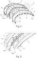
Figure 2 shows an axonometric and exploded view of a scraping device for the blades of a floor washing-drying machine according to the invention; -
Figure 3 shows the view of an end portion particular of the scraping device offigure 2 ; -
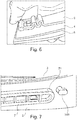
Figure 4 shows an axonometric view of a particular of a first assembling stage of a blade according to a first embodiment; -
Figure 5 shows an axonometric view of the particular infigure 4 in a second assembling stage; -
Figure 6 shows an axonometric view of the particular infigure 4 in the final assembling stage; -
Figure 7 shows a view of a particular of a first assembling stage of a blade according to a second form of embodiment of the invention; -
Figure 8 shows an axonometric view of the particular infigure 7 in a second assembling stage; -
Figure 9 shows an axonometric view of the particular infigure 7 in the final assembling stage; -
Figure 10 shows a rear axonometric view of the assembled scraping device infigure 2 ; -
Figure 11 shows a front axonometric view of the scraping device infigure 10 . - In
figure 1 with thereference number 10 it is shown an example of floor washing-drying machine. The floor washing-drying machines 10 are provided with a washing group 1 in the front and ascraping device 2 in the rear with respect to cleaning direction. Thescraping device 2 is apt to cleanse, that is to collect and suck in, the washing water used by the washing group for the floor cleaning. - The
scraping device 2, better shown in the explodedfigure 2 , conventionally comprises asupport 3 whereon at least ascraping blade support 3 delimits, by means of said at least one blade and the floor, a space or suction chamber (not shown) for the dirty washing water. In particular, thesupport 3 generally has a curved shape with a firstconcave surface 31 in the cleaning direction, that is at the front of the machine, and a secondconvex surface 32 in the direction opposite to that of the cleaning direction, that is at the rear of the machine. Both first 31 and second 32 surfaces are provided withsupport elements support 3 with a preset pitch. Preferably, these elements, on one or both first 31 and second 32 surfaces, have a mushroom shape so as to form an engaging undercut with the edges of the holes of therespective blades - Advantageously, as it will be better shown in
figure 3 , in correspondence with the end portions of thesupport 3 and on both first 31 and second 32 surfaces thereof a preferably hook-shaped fastening element fastening element 34A projecting from thefirst surface 31 of thesupport 3 is generally L-shaped with a segment facing the longitudinal end of the support. On the contrary, thefastening element 34B projecting from thesecond surface 32 of thesupport 3 is generally L-shaped too but with a segment facing the opposite end with respect to where it is situated. - As previously mentioned, at least one scraping blade, preferably two, can be mounted on the
support 3. Said at least one blade can be afirst blade 4 mounted on saidfirst surface 31 of thesupport 3, that is on the concave surface, and/or asecond blade 5 mounted on thesecond surface 32 of thesupport 3, that is on the convex surface. - The
first blade 4 is a longitudinal strip generally of rubbery material and provided with notches 41 to allow the passage of the liquid into the suction chamber. This blade therefore has the function of collecting the dirty washing liquid. Moreover, it is crossed by a plurality ofholes 42 for engaging with thesupport elements 33A formed on thefirst surface 31 of thesupport 3, as it will be explained later. - Similarly, the second blade is a longitudinal strip, notoriously, with the function of scraping the floor, that is drying, of rubbery material. Therefore, it has a basically uninterrupted contact edge with the floor and it is crossed by a plurality of holes 51 for engaging with the
corresponding support elements 33B. - The
scraping device 2 according to the present invention comprises, moreover, fastening or locking means apt to cooperate with saidsupport elements blades support 3 of the scraping device. Advantageously, said means comprise (figure 2 ) at least a flexible belt, perforated and provided with at least anelastic end portion slot hook support 3. - In particular, the
flexible belt 6, according to a first embodiment of the invention, is constituted by a strip of hard plastic but flexible material whose the opposite ends are provided with anelastic end portion 61, preferably having a serpentine shape providing the necessary elasticity for snap-engaging between theslot 62 and thecorresponding hook 34A, as later described in detail. Further, thebelt 6 is crossed by a plurality ofholes 63 apt to be engaged with thecorresponding support elements 33A. - Preferably, the
belt 6 acts as a locking or keeping means of thefirst blade 4 on thefront surface 31 of thesupport 3 of thescraping device 2. - In accordance with a variation of the embodiment of the invention, the fastening means comprise a
flexible belt 7 made of a strip of an elastic and soft polymeric material. The material can be natural rubber, India rubber, or synthetic rubber based on elastomeric polymers. In particular, theslot 72 formed in theelastic end portion 71 elastically engages with thehook 34B. Similarly, thebelt 7 is crossed byholes 73 having dimension and distance one from the other, or distance between centres, reduced with respect to thecorresponding support elements 33B arranged on thesecond surface 32 of thescraping device 2. - With reference to
figures 4-8 , it is herewith described the assembling of thescraping device 2 infigure 1 . Firstly, it is describe the locking of thefirst blade 4 and subsequently that of thesecond blade 5, even though this is not a binding order. - The locking of the
first blade 4 is carried out mounting thefirst blade 4 on thesurface 31 of thesupport 3. In particular, theholes 42 are engaged in therespective support elements 33A in the traditional way. Preferably, it is a snap engaging as theholes 42 are slightly smaller of the same support elements, such as when said elements have a mushroom-shape. - Then, the
first belt 6 is mounted on thefirst blade 4 engaging first theholes 63 with thesame support elements 33A. In this position (figure 4 ), the elastic ends 61 of said belt are placed above thehook 34A, but therespective slot 62 is not aligned with the hook. At this stage, as shown infigure 5 , theelastic end 61 is compressed thanks to the serpentine portion so as to align theslot 62 with thehook 34A. Now, it is possible to move this end towards the first blade so that the inner edge of the opening of theslot 62 crosses the undercut defined by the hook. Finally, it is sufficient to release theelastic end 61 to make it possible to engage the slot edge with said undercut, as shown infigure 6 . - The unlocking and the removal of the
first blade 4 are done in a simple and quick way carrying out the just described operations but in the reverse order. - It is to note that the flexibility together with the elasticity of its ends makes it possible for the
first belt 6 to engage the firstconcave surface 31 of thesupport 3 of thescraping device 2 compressing theblade 4 in a suitable way. Further, as thescraping device 2 is curved, such longitudinal compression gives a normal push to thebelt 6 which winds up onto the blade keeping it actually adherent to the same scraping device. In fact, whenbelt 6 is mounted, its length between the end hooks 33A is higher with respect to the length of the arch development of thefirst surface 31 of thesame support 3. In this configuration, thebelt 6 is compressed against the first blade 4 (figure 10 ). - The locking of the second blade 5 (
figures 7-9 ) is carried out first, mounting theblade 5 on thesecond surface 32 in exactly the same way as for the mounting of thefirst blade 4. In fact, theholes 52 are engaged by thesupport elements 33B projecting from thesecond surface 32, preferably providing a snap engaging thanks to the mushroom shape of the same elements. Subsequently, as shown infigure 8 , thesecond belt 7 is fastened on thesecond blade 5 engaging theholes 73 with thesupport elements 33B. Advantageously, as the distances between theholes 73, or the distances between centres of thesecond belt 7 are reduced with respect to those of therespective support elements 33B, this operation occurs by stretching the same belt thanks to its elastic nature in order to lengthen it enough so as to centre said holes with saidsupport elements 33B. Once the centring has been carried out, in order to obtain the desired engagement, it is enough to push the belt against the support elements and release the belt. Similarly, the undercut of thehook 34B is engaged by theslot 72 pulling the belt and releasing it after the slot has passed said undercut. - It is to note that the elastic traction the belt undergoes in the locking position ensures an adequate compression of the blade along its entire longitudinal extension.
- Advantageously, moreover, the mushroom shape of the
support elements 33B further ensure the snap-engaging withbelt 7, again in order to ensure the necessary compression of the blade against thesupport 3 of thescraping device 2. Thehook 34B, on each end of thebelt 7, in addition ensures an optimal endurance also in case of frontal shocks/bumps that tend to tear the blade in its rear part (figure 9 ). - As previously, the removal is very easy and quick as, thanks to the elasticity of the same belt, it is sufficient to unhook each hole from the locking elements acting in the reverse way with respect to the foregoing.
- Preferably, the
belt 7 can be provided with a gripping means (not shown), for example tongue shaped projecting from the plane of the same belt and placed in correspondence of theslot 73, so as to facilitate gripping and handling in the assembling and disassembling stages. - From the foregoing, it can be understood that the inconveniences described in the introductory part of the present invention have been overcome.
- In particular, the fastening system according to the present invention avoids using hooking elements made of screws or mobile hooks.
- It is not necessary for the user to use any tools and to waste a lot of time assembling the scraping device.
- Consequently, the fastening system has been simplified reducing, on the one hand, the number of components to handle and on the other, simplifying the operations needed when assembling the scraping device.
- Nevertheless, the system reliability has not been hindered at all as the blades are efficiently compressed against the support of the scraping device.
- A lot of modifications can be carried out by the skilled in the field without exiting the protection field of the present invention according to the appended claims.
- For example, the
support elements support 3 and the correspondingholes - The support elements can be formed on the fastening means 6 and 7 so as to engage the corresponding seats on the
surfaces support 3. - Similarly, the locking hooks 34A and 34B can be formed on the fastening means 6, 7 and the corresponding slots on the
surfaces support 3. - The
support 3 of thescraping device 2 can be provided with a fastening system of the blades comprising one of the twobelts respective blade - The materials used to make the fastening elements can be traditional hard but flexible plastic materials for the
first fastening element 6, such as polyamide polymers, polypropylenes, polyethylene and elastomeric polymers for the second fastening means 7, such as natural rubber, synthetic rubber such as butadienestyrene, polyurethane, silicone rubber. - The elastic serpentine in correspondence of the
ends 61 of thefirst belt 6 or fastening means can be replaced by a similar elastic means such as a traditional spring suitably fixed to the same belt.
Claims (10)
- Floor washing drying machine (10) comprising a scraping device (2) provided with a curved support (3) on which at least one perforated scraping blade (4, 5) is mounted in a reversible manner by means of support elements (33A, 33B) and therein reversibly blocked by fastening means (6, 7), said fastening means comprising at least a flexible belt (6,7) provided with holes (63, 73) to engage with said support elements (33A, 33B), characterized in that said fastening means is further provided with at least an elastic end portion (61, 71) bearing a slot (62, 72) to engage with a corresponding fastening element (34A, 34B) formed close to the end portions of the support (3).
- Floor washing drying machine (10) according to claim 1, wherein said at least one said flexible fastening belt (6) of said at least one blade (4) is constituted by a strip of hard plastic material ending on both sides with said elastic end portion (61).
- Floor washing drying machine (10) according to claim 2, wherein said elastic end portion (61) is shaped as an elastically compressible serpentine followed, toward the outer edge, by said slot (62) for snap-engaging with an undercut of said locking element (34A).
- Floor washing drying machine (10) according to any of preceding claims 1 to 3, wherein said at least one belt (6) acts as a fastening device to fasten said blade (4) on a first concave surface (31) of the support (3) of the scraping device (2).
- Floor washing drying machine (10) according to claim 1, wherein said at least one flexible fastening belt (7) of said blade (5) is constituted by a strip of elastomeric material.
- Floor washing drying machine (10) according to claim 5, wherein said holes (73) of said at least one belt (7) for engagement with the support elements (33B) have a distance between each other shorter than that of said support elements and said slot (72) elastically engages with an undercut of said fastening element (34B).
- Floor washing drying machine (10) according to claims 5 or 6, wherein said terminal section (71) of said belt (7) comprises gripping elements.
- Floor washing drying machine (10) according to any one of claims 2 to 7, wherein said at least one belt (7) acts as fastening means for said blade (5) on a second convex surface (32) of the support (3) of the scraping device (2).
- Floor washing drying machine (10) according to any one of claims 1 to 8, wherein said scraping device (2) comprises a first concave surface (31) on which a first blade (4) is mounted for collecting dirt washing liquid, said first blade being herein fastened by means of a first belt (6) according to any one of claims 2 to 4, and a second convex surface (32) on which a second blade (5) is mounted to dry the dirt washing liquid, said second blade being fastened by means of a second belt (7) according to any one of claims 5 to 8.
- Floor washing drying machine (10) according to any one of preceding claims 1 to 9, wherein said support elements (33A, 33B) have a mushroom shape.
Applications Claiming Priority (2)
| Application Number | Priority Date | Filing Date | Title |
|---|---|---|---|
| IT000011A ITPN20130011A1 (en) | 2013-02-15 | 2013-02-15 | FLOOR DRYING AND FLOOR CLEANING MACHINE WITH WASHING DEVICE EQUIPPED WITH A REVERSIBLE STRIPPING SYSTEM |
| PCT/IB2013/060865 WO2014125347A1 (en) | 2013-02-15 | 2013-12-12 | Floor washing-drying machine with a scraping device |
Publications (2)
| Publication Number | Publication Date |
|---|---|
| EP2956044A1 EP2956044A1 (en) | 2015-12-23 |
| EP2956044B1 true EP2956044B1 (en) | 2017-04-26 |
Family
ID=47953586
Family Applications (1)
| Application Number | Title | Priority Date | Filing Date |
|---|---|---|---|
| EP13820982.0A Active EP2956044B1 (en) | 2013-02-15 | 2013-12-12 | Floor washing-drying machine with a scraping device |
Country Status (4)
| Country | Link |
|---|---|
| US (1) | US9516985B2 (en) |
| EP (1) | EP2956044B1 (en) |
| IT (1) | ITPN20130011A1 (en) |
| WO (1) | WO2014125347A1 (en) |
Families Citing this family (3)
| Publication number | Priority date | Publication date | Assignee | Title |
|---|---|---|---|---|
| DE102015109778B3 (en) * | 2015-06-18 | 2016-09-22 | Hako Gmbh | Scrub deck for a floor cleaning machine |
| CN109044213B (en) * | 2018-07-28 | 2021-05-25 | 安徽南博机器人有限公司 | A hand push washing machine |
| CN109106295A (en) * | 2018-07-28 | 2019-01-01 | 安徽南博机器人有限公司 | A kind of floor-cleaning machine scrapes water rake rubber pressing device |
Family Cites Families (4)
| Publication number | Priority date | Publication date | Assignee | Title |
|---|---|---|---|---|
| ITPN20060086A1 (en) * | 2006-11-03 | 2008-05-04 | Cfm Nilfisk Advance S P A | FLOOR WASHING MACHINE |
| US9038237B2 (en) | 2009-03-18 | 2015-05-26 | Nilfisk-Advance, Inc. | Squeegee assembly |
| EP2498660B1 (en) | 2009-11-09 | 2016-11-02 | Tennant Company | Squeegee assembly |
| DE102014107469B3 (en) * | 2014-05-27 | 2015-04-16 | Hako Gmbh | Suction cup for a floor cleaning machine |
-
2013
- 2013-02-15 IT IT000011A patent/ITPN20130011A1/en unknown
- 2013-12-12 EP EP13820982.0A patent/EP2956044B1/en active Active
- 2013-12-12 US US14/761,159 patent/US9516985B2/en active Active
- 2013-12-12 WO PCT/IB2013/060865 patent/WO2014125347A1/en not_active Ceased
Non-Patent Citations (1)
| Title |
|---|
| None * |
Also Published As
| Publication number | Publication date |
|---|---|
| US20150359398A1 (en) | 2015-12-17 |
| ITPN20130011A1 (en) | 2014-08-16 |
| EP2956044A1 (en) | 2015-12-23 |
| WO2014125347A1 (en) | 2014-08-21 |
| US9516985B2 (en) | 2016-12-13 |
Similar Documents
| Publication | Publication Date | Title |
|---|---|---|
| US6564417B2 (en) | Cylindrical brush with locking pin | |
| US9516985B2 (en) | Floor washing-drying machine with a scraping device | |
| EP1871214B1 (en) | Nubby mitt for debris removal | |
| US7716785B2 (en) | Floor cleaning machine | |
| US8661612B2 (en) | Circular liquid wiper device for a floor cleaning machine | |
| US20120048689A1 (en) | Link for a link conveyor | |
| EP1644196B1 (en) | Equipment for cleaning rubber cylinders of continuous printing machines | |
| CN104224057A (en) | Bottom cover structure of sweeper of self-propelled cleaning device and assembling and sweeping methods thereof | |
| CN114845615B (en) | Cleaning devices, mopping cloths and cleaning systems | |
| JP5861953B1 (en) | Belt cleaner | |
| US10376121B2 (en) | Squeegee with seal flap | |
| JP2002307315A (en) | Abrasive paper fixings | |
| US20190053684A1 (en) | Reversable blade squeegee with winglet tips | |
| CN113558537A (en) | Mop assembly of cleaning robot | |
| RU2407345C2 (en) | Cleaning element, unit, cleaning device and methods of engagement and disengagement | |
| JP3661208B2 (en) | Floor nozzle for vacuum cleaner | |
| CN217460026U (en) | Lint cleaning device and clothes treatment equipment | |
| WO2013182918A1 (en) | Floor -cleaning machine having a longlife scrapping blade | |
| CN107877362B (en) | Tool for removing sanding or polishing plates | |
| CN223026018U (en) | Dustpan | |
| CN221997771U (en) | Mop with bendable bottom plate | |
| CN223275369U (en) | Dust collector nozzle and small handheld dust collector | |
| CN113142955A (en) | Combined household bathroom anti-skid mat | |
| CN222521593U (en) | Edge sealing device for processing purification plate | |
| US20160113468A1 (en) | Device for a Ringformed Scraper Intended for a Floor Treatment Machine |
Legal Events
| Date | Code | Title | Description |
|---|---|---|---|
| PUAI | Public reference made under article 153(3) epc to a published international application that has entered the european phase |
Free format text: ORIGINAL CODE: 0009012 |
|
| 17P | Request for examination filed |
Effective date: 20150817 |
|
| AK | Designated contracting states |
Kind code of ref document: A1 Designated state(s): AL AT BE BG CH CY CZ DE DK EE ES FI FR GB GR HR HU IE IS IT LI LT LU LV MC MK MT NL NO PL PT RO RS SE SI SK SM TR |
|
| AX | Request for extension of the european patent |
Extension state: BA ME |
|
| DAX | Request for extension of the european patent (deleted) | ||
| GRAP | Despatch of communication of intention to grant a patent |
Free format text: ORIGINAL CODE: EPIDOSNIGR1 |
|
| INTG | Intention to grant announced |
Effective date: 20170103 |
|
| RIN1 | Information on inventor provided before grant (corrected) |
Inventor name: ODOLI, ANDREA Inventor name: CHIGNOLI, ANDREA |
|
| GRAS | Grant fee paid |
Free format text: ORIGINAL CODE: EPIDOSNIGR3 |
|
| GRAA | (expected) grant |
Free format text: ORIGINAL CODE: 0009210 |
|
| RAP1 | Party data changed (applicant data changed or rights of an application transferred) |
Owner name: NILFISK A/S |
|
| AK | Designated contracting states |
Kind code of ref document: B1 Designated state(s): AL AT BE BG CH CY CZ DE DK EE ES FI FR GB GR HR HU IE IS IT LI LT LU LV MC MK MT NL NO PL PT RO RS SE SI SK SM TR |
|
| REG | Reference to a national code |
Ref country code: GB Ref legal event code: FG4D |
|
| REG | Reference to a national code |
Ref country code: CH Ref legal event code: EP |
|
| REG | Reference to a national code |
Ref country code: AT Ref legal event code: REF Ref document number: 887159 Country of ref document: AT Kind code of ref document: T Effective date: 20170515 |
|
| REG | Reference to a national code |
Ref country code: IE Ref legal event code: FG4D |
|
| REG | Reference to a national code |
Ref country code: DE Ref legal event code: R096 Ref document number: 602013020418 Country of ref document: DE |
|
| REG | Reference to a national code |
Ref country code: NL Ref legal event code: MP Effective date: 20170426 |
|
| REG | Reference to a national code |
Ref country code: LT Ref legal event code: MG4D |
|
| REG | Reference to a national code |
Ref country code: AT Ref legal event code: MK05 Ref document number: 887159 Country of ref document: AT Kind code of ref document: T Effective date: 20170426 |
|
| PG25 | Lapsed in a contracting state [announced via postgrant information from national office to epo] |
Ref country code: NL Free format text: LAPSE BECAUSE OF FAILURE TO SUBMIT A TRANSLATION OF THE DESCRIPTION OR TO PAY THE FEE WITHIN THE PRESCRIBED TIME-LIMIT Effective date: 20170426 |
|
| PG25 | Lapsed in a contracting state [announced via postgrant information from national office to epo] |
Ref country code: FI Free format text: LAPSE BECAUSE OF FAILURE TO SUBMIT A TRANSLATION OF THE DESCRIPTION OR TO PAY THE FEE WITHIN THE PRESCRIBED TIME-LIMIT Effective date: 20170426 Ref country code: ES Free format text: LAPSE BECAUSE OF FAILURE TO SUBMIT A TRANSLATION OF THE DESCRIPTION OR TO PAY THE FEE WITHIN THE PRESCRIBED TIME-LIMIT Effective date: 20170426 Ref country code: HR Free format text: LAPSE BECAUSE OF FAILURE TO SUBMIT A TRANSLATION OF THE DESCRIPTION OR TO PAY THE FEE WITHIN THE PRESCRIBED TIME-LIMIT Effective date: 20170426 Ref country code: GR Free format text: LAPSE BECAUSE OF FAILURE TO SUBMIT A TRANSLATION OF THE DESCRIPTION OR TO PAY THE FEE WITHIN THE PRESCRIBED TIME-LIMIT Effective date: 20170727 Ref country code: LT Free format text: LAPSE BECAUSE OF FAILURE TO SUBMIT A TRANSLATION OF THE DESCRIPTION OR TO PAY THE FEE WITHIN THE PRESCRIBED TIME-LIMIT Effective date: 20170426 Ref country code: AT Free format text: LAPSE BECAUSE OF FAILURE TO SUBMIT A TRANSLATION OF THE DESCRIPTION OR TO PAY THE FEE WITHIN THE PRESCRIBED TIME-LIMIT Effective date: 20170426 Ref country code: NO Free format text: LAPSE BECAUSE OF FAILURE TO SUBMIT A TRANSLATION OF THE DESCRIPTION OR TO PAY THE FEE WITHIN THE PRESCRIBED TIME-LIMIT Effective date: 20170726 |
|
| PG25 | Lapsed in a contracting state [announced via postgrant information from national office to epo] |
Ref country code: RS Free format text: LAPSE BECAUSE OF FAILURE TO SUBMIT A TRANSLATION OF THE DESCRIPTION OR TO PAY THE FEE WITHIN THE PRESCRIBED TIME-LIMIT Effective date: 20170426 Ref country code: SE Free format text: LAPSE BECAUSE OF FAILURE TO SUBMIT A TRANSLATION OF THE DESCRIPTION OR TO PAY THE FEE WITHIN THE PRESCRIBED TIME-LIMIT Effective date: 20170426 Ref country code: BG Free format text: LAPSE BECAUSE OF FAILURE TO SUBMIT A TRANSLATION OF THE DESCRIPTION OR TO PAY THE FEE WITHIN THE PRESCRIBED TIME-LIMIT Effective date: 20170726 Ref country code: LV Free format text: LAPSE BECAUSE OF FAILURE TO SUBMIT A TRANSLATION OF THE DESCRIPTION OR TO PAY THE FEE WITHIN THE PRESCRIBED TIME-LIMIT Effective date: 20170426 Ref country code: IS Free format text: LAPSE BECAUSE OF FAILURE TO SUBMIT A TRANSLATION OF THE DESCRIPTION OR TO PAY THE FEE WITHIN THE PRESCRIBED TIME-LIMIT Effective date: 20170826 Ref country code: PL Free format text: LAPSE BECAUSE OF FAILURE TO SUBMIT A TRANSLATION OF THE DESCRIPTION OR TO PAY THE FEE WITHIN THE PRESCRIBED TIME-LIMIT Effective date: 20170426 |
|
| REG | Reference to a national code |
Ref country code: FR Ref legal event code: PLFP Year of fee payment: 5 |
|
| REG | Reference to a national code |
Ref country code: DE Ref legal event code: R097 Ref document number: 602013020418 Country of ref document: DE |
|
| PG25 | Lapsed in a contracting state [announced via postgrant information from national office to epo] |
Ref country code: SK Free format text: LAPSE BECAUSE OF FAILURE TO SUBMIT A TRANSLATION OF THE DESCRIPTION OR TO PAY THE FEE WITHIN THE PRESCRIBED TIME-LIMIT Effective date: 20170426 Ref country code: CZ Free format text: LAPSE BECAUSE OF FAILURE TO SUBMIT A TRANSLATION OF THE DESCRIPTION OR TO PAY THE FEE WITHIN THE PRESCRIBED TIME-LIMIT Effective date: 20170426 Ref country code: DK Free format text: LAPSE BECAUSE OF FAILURE TO SUBMIT A TRANSLATION OF THE DESCRIPTION OR TO PAY THE FEE WITHIN THE PRESCRIBED TIME-LIMIT Effective date: 20170426 Ref country code: RO Free format text: LAPSE BECAUSE OF FAILURE TO SUBMIT A TRANSLATION OF THE DESCRIPTION OR TO PAY THE FEE WITHIN THE PRESCRIBED TIME-LIMIT Effective date: 20170426 Ref country code: EE Free format text: LAPSE BECAUSE OF FAILURE TO SUBMIT A TRANSLATION OF THE DESCRIPTION OR TO PAY THE FEE WITHIN THE PRESCRIBED TIME-LIMIT Effective date: 20170426 |
|
| PG25 | Lapsed in a contracting state [announced via postgrant information from national office to epo] |
Ref country code: SM Free format text: LAPSE BECAUSE OF FAILURE TO SUBMIT A TRANSLATION OF THE DESCRIPTION OR TO PAY THE FEE WITHIN THE PRESCRIBED TIME-LIMIT Effective date: 20170426 |
|
| PLBE | No opposition filed within time limit |
Free format text: ORIGINAL CODE: 0009261 |
|
| STAA | Information on the status of an ep patent application or granted ep patent |
Free format text: STATUS: NO OPPOSITION FILED WITHIN TIME LIMIT |
|
| 26N | No opposition filed |
Effective date: 20180129 |
|
| PG25 | Lapsed in a contracting state [announced via postgrant information from national office to epo] |
Ref country code: SI Free format text: LAPSE BECAUSE OF FAILURE TO SUBMIT A TRANSLATION OF THE DESCRIPTION OR TO PAY THE FEE WITHIN THE PRESCRIBED TIME-LIMIT Effective date: 20170426 |
|
| REG | Reference to a national code |
Ref country code: CH Ref legal event code: PL |
|
| REG | Reference to a national code |
Ref country code: IE Ref legal event code: MM4A |
|
| PG25 | Lapsed in a contracting state [announced via postgrant information from national office to epo] |
Ref country code: MT Free format text: LAPSE BECAUSE OF NON-PAYMENT OF DUE FEES Effective date: 20171212 Ref country code: LU Free format text: LAPSE BECAUSE OF NON-PAYMENT OF DUE FEES Effective date: 20171212 |
|
| REG | Reference to a national code |
Ref country code: BE Ref legal event code: MM Effective date: 20171231 |
|
| PG25 | Lapsed in a contracting state [announced via postgrant information from national office to epo] |
Ref country code: IE Free format text: LAPSE BECAUSE OF NON-PAYMENT OF DUE FEES Effective date: 20171212 |
|
| PG25 | Lapsed in a contracting state [announced via postgrant information from national office to epo] |
Ref country code: LI Free format text: LAPSE BECAUSE OF NON-PAYMENT OF DUE FEES Effective date: 20171231 Ref country code: BE Free format text: LAPSE BECAUSE OF NON-PAYMENT OF DUE FEES Effective date: 20171231 Ref country code: CH Free format text: LAPSE BECAUSE OF NON-PAYMENT OF DUE FEES Effective date: 20171231 |
|
| PG25 | Lapsed in a contracting state [announced via postgrant information from national office to epo] |
Ref country code: MC Free format text: LAPSE BECAUSE OF FAILURE TO SUBMIT A TRANSLATION OF THE DESCRIPTION OR TO PAY THE FEE WITHIN THE PRESCRIBED TIME-LIMIT Effective date: 20170426 Ref country code: HU Free format text: LAPSE BECAUSE OF FAILURE TO SUBMIT A TRANSLATION OF THE DESCRIPTION OR TO PAY THE FEE WITHIN THE PRESCRIBED TIME-LIMIT; INVALID AB INITIO Effective date: 20131212 |
|
| PG25 | Lapsed in a contracting state [announced via postgrant information from national office to epo] |
Ref country code: CY Free format text: LAPSE BECAUSE OF FAILURE TO SUBMIT A TRANSLATION OF THE DESCRIPTION OR TO PAY THE FEE WITHIN THE PRESCRIBED TIME-LIMIT Effective date: 20170426 |
|
| PG25 | Lapsed in a contracting state [announced via postgrant information from national office to epo] |
Ref country code: MK Free format text: LAPSE BECAUSE OF FAILURE TO SUBMIT A TRANSLATION OF THE DESCRIPTION OR TO PAY THE FEE WITHIN THE PRESCRIBED TIME-LIMIT Effective date: 20170426 |
|
| PG25 | Lapsed in a contracting state [announced via postgrant information from national office to epo] |
Ref country code: TR Free format text: LAPSE BECAUSE OF FAILURE TO SUBMIT A TRANSLATION OF THE DESCRIPTION OR TO PAY THE FEE WITHIN THE PRESCRIBED TIME-LIMIT Effective date: 20170426 |
|
| PG25 | Lapsed in a contracting state [announced via postgrant information from national office to epo] |
Ref country code: PT Free format text: LAPSE BECAUSE OF FAILURE TO SUBMIT A TRANSLATION OF THE DESCRIPTION OR TO PAY THE FEE WITHIN THE PRESCRIBED TIME-LIMIT Effective date: 20170426 |
|
| PG25 | Lapsed in a contracting state [announced via postgrant information from national office to epo] |
Ref country code: AL Free format text: LAPSE BECAUSE OF FAILURE TO SUBMIT A TRANSLATION OF THE DESCRIPTION OR TO PAY THE FEE WITHIN THE PRESCRIBED TIME-LIMIT Effective date: 20170426 |
|
| P01 | Opt-out of the competence of the unified patent court (upc) registered |
Effective date: 20230515 |
|
| REG | Reference to a national code |
Ref country code: DE Ref legal event code: R081 Ref document number: 602013020418 Country of ref document: DE Owner name: NILFISK A/S, DK Free format text: FORMER OWNER: NILFISK A/S, BROENDBY, DK |
|
| PGFP | Annual fee paid to national office [announced via postgrant information from national office to epo] |
Ref country code: DE Payment date: 20251126 Year of fee payment: 13 |
|
| PGFP | Annual fee paid to national office [announced via postgrant information from national office to epo] |
Ref country code: GB Payment date: 20251119 Year of fee payment: 13 |
|
| PGFP | Annual fee paid to national office [announced via postgrant information from national office to epo] |
Ref country code: IT Payment date: 20251119 Year of fee payment: 13 |
|
| PGFP | Annual fee paid to national office [announced via postgrant information from national office to epo] |
Ref country code: FR Payment date: 20251120 Year of fee payment: 13 |