EP2955912B1 - Portable device and manipulation method for triggering different functions with a manipulation input - Google Patents
Portable device and manipulation method for triggering different functions with a manipulation input Download PDFInfo
- Publication number
- EP2955912B1 EP2955912B1 EP15169540.0A EP15169540A EP2955912B1 EP 2955912 B1 EP2955912 B1 EP 2955912B1 EP 15169540 A EP15169540 A EP 15169540A EP 2955912 B1 EP2955912 B1 EP 2955912B1
- Authority
- EP
- European Patent Office
- Prior art keywords
- manipulation
- switch button
- camera unit
- portable device
- video
- Prior art date
- Legal status (The legal status is an assumption and is not a legal conclusion. Google has not performed a legal analysis and makes no representation as to the accuracy of the status listed.)
- Active
Links
Images


Classifications
-
- H—ELECTRICITY
- H04—ELECTRIC COMMUNICATION TECHNIQUE
- H04N—PICTORIAL COMMUNICATION, e.g. TELEVISION
- H04N23/00—Cameras or camera modules comprising electronic image sensors; Control thereof
- H04N23/60—Control of cameras or camera modules
- H04N23/62—Control of parameters via user interfaces
-
- G—PHYSICS
- G06—COMPUTING OR CALCULATING; COUNTING
- G06F—ELECTRIC DIGITAL DATA PROCESSING
- G06F3/00—Input arrangements for transferring data to be processed into a form capable of being handled by the computer; Output arrangements for transferring data from processing unit to output unit, e.g. interface arrangements
- G06F3/01—Input arrangements or combined input and output arrangements for interaction between user and computer
- G06F3/011—Arrangements for interaction with the human body, e.g. for user immersion in virtual reality
-
- H—ELECTRICITY
- H04—ELECTRIC COMMUNICATION TECHNIQUE
- H04N—PICTORIAL COMMUNICATION, e.g. TELEVISION
- H04N21/00—Selective content distribution, e.g. interactive television or video on demand [VOD]
- H04N21/40—Client devices specifically adapted for the reception of or interaction with content, e.g. set-top-box [STB]; Operations thereof
- H04N21/41—Structure of client; Structure of client peripherals
- H04N21/422—Input-only peripherals, i.e. input devices connected to specially adapted client devices, e.g. global positioning system [GPS]
- H04N21/4223—Cameras
-
- H—ELECTRICITY
- H04—ELECTRIC COMMUNICATION TECHNIQUE
- H04N—PICTORIAL COMMUNICATION, e.g. TELEVISION
- H04N23/00—Cameras or camera modules comprising electronic image sensors; Control thereof
- H04N23/60—Control of cameras or camera modules
- H04N23/667—Camera operation mode switching, e.g. between still and video, sport and normal or high- and low-resolution modes
-
- H—ELECTRICITY
- H04—ELECTRIC COMMUNICATION TECHNIQUE
- H04N—PICTORIAL COMMUNICATION, e.g. TELEVISION
- H04N5/00—Details of television systems
- H04N5/38—Transmitter circuitry for the transmission of television signals according to analogue transmission standards
-
- H—ELECTRICITY
- H04—ELECTRIC COMMUNICATION TECHNIQUE
- H04N—PICTORIAL COMMUNICATION, e.g. TELEVISION
- H04N5/00—Details of television systems
- H04N5/76—Television signal recording
- H04N5/765—Interface circuits between an apparatus for recording and another apparatus
- H04N5/77—Interface circuits between an apparatus for recording and another apparatus between a recording apparatus and a television camera
- H04N5/772—Interface circuits between an apparatus for recording and another apparatus between a recording apparatus and a television camera the recording apparatus and the television camera being placed in the same enclosure
Definitions
- the invention relates to a manipulation method. More particularly, the invention relates to a manipulation method of selecting between different functional modes according to a manipulation input.
- a portable device e.g., smart phones, digital cameras, sports cameras, tablets, or similar handheld devices
- the portable device has ten different functions and each of the functions requires an individual button to manipulate (e.g., trigger, control, configure, etc), the portable device must has at least ten individual buttons. In this case, each of the ten buttons will be small, hard to locate and easy to be damaged. On the other hand, the size of the portable device must be enlarged for accommodating these buttons. It is a dilemma between increasing the mobility or the manoeuvrability of the portable device. However, the cutting-edge portable device must be capable to fulfil many functions within a compact size.
- a multi-purpose input sensor e.g., button, key, switch, etc.
- the portable device includes a camera unit, a first sensor and a control module.
- the camera unit has a plurality of functional modes.
- the functional modes include a photo-capturing mode and a video-recording mode.
- the first sensor is disposed on the portable device and configured for sensing a manipulation input.
- the manipulation input has a manipulation pattern and duration information of aforesaid manipulation pattern.
- the control module is coupled with the camera unit and the first sensor. The control module is configured for selecting one of the functional modes corresponding to the manipulation pattern and the duration information sensed by the first sensor, and triggering the camera unit into the selected functional mode.
- At least one embodiment of the disclosure provides a manipulation method, which is suitable for the portable device includes a camera unit.
- the camera unit has a plurality of functional modes including a photo-capturing mode and a video-recording mode.
- the manipulation method includes steps of: sensing a manipulation input; extracting a manipulation pattern and duration information of aforesaid manipulation pattern from the manipulation input; selecting one of the functional modes corresponding to the manipulation pattern according to the manipulation pattern and the duration information; and, triggering the camera unit into the selected functional mode.
- Another aspect of the disclosure is to provide a non-transitory computer readable storage medium with a computer program to execute aforesaid manipulation method.
- FIG. 1 is a schematic diagram illustrating a portable device 100 according to an embodiment of this disclosure.
- the portable device 100 includes a camera unit 120, a first sensor 140 and a control module 160.
- the portable device 100 can be a sports camera, a versatile camera, a smart phone, a digital camera, a tablet, or a similar handheld device.
- the camera unit 120 of the portable device 100 includes lens, an optical sensor component, a focusing motor and/or a digital signal processor (DSP) for processing an image or a video captured by the camera unit 120.
- DSP digital signal processor
- the camera unit 120 has several functional modes.
- the functional modes at least include a photo-capturing mode and a video-recording mode.
- the camera unit 120 is able to capture a photograph in response to a photo-shooting command (e.g., a manipulation input from a user).
- a photo-shooting command e.g., a manipulation input from a user
- the camera unit 120 is able to record a video in response to a video-recording command (e.g., another manipulation input from the user).
- the camera unit 120 is not limited to aforesaid two functional modes.
- the camera unit 120 may further have a burst-capturing mode, which is utilized to capture a series of photographs in sequence; and, the camera unit 120 may further have a broadcasting mode, which is utilized to live broadcasting a streaming video recorded by the camera unit 120.
- the portable device 100 further includes a communication unit 180 for exchanging information with at least one external terminal (e.g., a server of Youtube, Twitch, HTC ZOE, or any equivalent streaming video terminal).
- the streaming video recorded by the camera unit 120 can be transmitted to the external terminal.
- buttons e.g., a shutter button and a recording button
- the first sensor 140 is a switch button disposed on the portable device 100.
- the switch button can be manipulated by the user (e.g., click, double click, press down, press and hold, etc.). Based on how the user manipulates the switch button, the first sensor 140 will generate a corresponding manipulation input.
- the first sensor 140 is utilized to generate different commands (e.g., the photo-shooting command, the video-recording command, etc.), for triggering the camera unit 120 into different functional modes with only one switch button.
- the manipulation input generated by the first sensor 140 has a manipulation pattern and duration information of aforesaid manipulation pattern.
- the manipulation pattern is related to a behavior, a count, a distribution about how the user manipulates the switch button (e.g., the user clicks the switch button once, the user clicks the switch button several times in a row, the user presses the switch button down and holds the switch button).
- the duration information of the manipulation pattern is related to how long the switch button has been pressed down. In some embodiments, the duration information is counted separately for each time the switch button is pressed.
- the control module 160 is coupled with the camera unit 120 and the first sensor 140.
- the control module 160 is configured for selecting one of the functional modes corresponding to the manipulation pattern and the duration information sensed by the first sensor, and triggering the camera unit into the selected functional mode.
- the control module 160 is a processor, a central processing unit, a control integrated chip, or a System-on-Chip (SoC) for executing some programs/instructions, performing computations and/or managing some processes of the portable device 100.
- SoC System-on-Chip
- the portable device 100 further includes a second sensor 142.
- the second sensor 142 is disposed on the portable device 100.
- the second sensor 142 is a pressure sensor and configured for sensing a pressure value on a surface of the portable device 100.
- the control module 160 is further coupled with the second sensor 142 and configured for determining whether the portable device 100 is gripped by the user.
- the first sensor 140 is deactivated in response to the portable device 100 is not gripped by the user.
- FIG. 2 to FIG. 5 are schematic diagrams illustrating the manipulation input MP1/MP2/MP3/MP4 sensed by the first sensor 140 in four different examples according to the embodiment.
- the first sensor 120 generates the manipulation input MP1, which indicates that the switch button is pressed down (at the time point T1a) and then released (at the time point T2a) within a first predetermined duration PD1.
- the first predetermined duration is utilized as a reference to identify the manipulation pattern of the manipulation input MP1 ⁇ MP4.
- the first predetermined duration PD1 in the example is about 1 second for demonstration, but the first predetermined duration PD1 is not limited to 1 second.
- the press-and-hold duration D1 between the time points T1a and T2a is shorter than the first predetermined duration PD1. Therefore, the manipulation pattern of the manipulation input MP1 corresponding to the press-and-hold duration D1 is regarded as a "click" pattern.
- the photo-capturing mode is selected by the control module 160, and the camera unit 120 is triggered to capture a photo PHO1 corresponding to the press-and-hold duration D1.
- the photo PHO1 can be pre-captured at time point T1 a (at the moment when the switch button is just pressed), or the photo PHO1 can be captured at time point T2a (right after the switch button is just released).
- the switch button is pressed down again (at the time point T3a) and then released again (at the time point T4a) within the first predetermined duration PD1.
- the press-and-hold duration D2 between the time points T3a and T4a is also shorter than the first predetermined duration PD1. Therefore, the manipulation pattern of the manipulation input MP1 corresponding to the press-and-hold duration D2 is also regarded as another "click" pattern.
- the photo-capturing mode is selected by the control module 160, and the camera unit 120 is triggered to capture another photo PHO2 corresponding to the press-and-hold duration D2.
- the photo PHO2 can be captured at time point T3a or T4a.
- the switch button is pressed down again (at the time point T5a) and then released again (at the time point T6a) within the first predetermined duration PD1.
- the manipulation pattern of the manipulation input MP1 corresponding to the press-and-hold duration D3 (between T5a and T6a) is also regarded as another "click" pattern.
- the photo-capturing mode is selected by the control module 160, and the camera unit 120 is triggered to capture another photo corresponding to the press-and-hold duration D3.
- the photo PHO3 can be captured at time point T5a or T6a.
- the manipulation input MP1 includes any press-and-hold duration D1/D2/D3 shorter than the first predetermined duration PD1, the press-and-hold duration D1/D2/D3 will be viewed as a "click" pattern.
- the camera unit 120 is triggered to capture one photo PHO1/PHO2/PHO3
- the video-recording mode is selected by the control module 140, and the camera unit 120 is triggered into the video-recording mode for recording a video VDO1 in response to the manipulation input.
- the first sensor 120 generates the manipulation input MP2, which indicates that the switch button is pressed down (at the time point T1 b), held over the first predetermined duration PD1, and then released (at the time point T3b) within a second predetermined duration PD2.
- the second predetermined duration PD2 is longer than the first predetermined duration PD1.
- the second predetermined duration PD2 is also utilized as a reference to identify the manipulation pattern of the manipulation input MP1 ⁇ MP4.
- the second predetermined duration PD2 in the example is about 3 seconds for demonstration, and not limited to 3 seconds.
- the press-and-hold duration D4 between the time points T1b and T3b is longer than the first predetermined duration PD1 and shorter than the second predetermined duration PD2.
- the manipulation pattern of the manipulation input MP2 corresponding to the press-and-hold duration D4 is regarded as a "short-press" pattern.
- the video-recording mode is selected by the control module 160, and the camera unit 120 is triggered to record the video VDO1 started from the time point T2b (at the moment when the switch button is pressed and held after the predetermined duration PD1).
- the video-recording mode of the camera unit 120 is stopped when the switch button is released (at the time point T3b).
- a photo PHO4 is captured by the camera unit 120 at the time point T1 b in addition to the video VDO1.
- the first sensor 120 generates the manipulation input MP3, which indicates that the switch button is pressed down (at the time point T1c), held over the first predetermined duration PD1 and the second predetermined duration PD2, and then released at the time point T3c.
- the press-and-hold duration D5 between the time points T1c and T3c is longer than the first predetermined duration PD1 and the second predetermined duration PD2.
- the manipulation pattern of the manipulation input MP3 corresponding to the press-and-hold duration D5 is regarded as a "long-press" pattern.
- the video-recording mode is selected by the control module 160, and the camera unit 120 is triggered to record the video VDO2 started from the time point T2b (at the moment when the switch button is pressed and held after the predetermined duration PD1).
- the camera unit 120 is locked (e.g., continuously operated) in the video-recording mode and keeps on recording the video VDO2.
- the manipulation input MP3 further indicates that the switch button is pressed down (at the time point T4c) and released within the first predetermined duration PD1 (at the time point T5c).
- the press-and-hold duration D6 between the time points T4c and T5c is shorter than the first predetermined duration PD1.
- the manipulation pattern of the manipulation input MP3 corresponding to the press-and-hold duration D6 is regarded as a "click" pattern.
- the video-recording mode of the camera unit 120 is stopped when the switch button is released (at the time point T5c) corresponding to the "click" pattern.
- the "long-press" pattern of the manipulation input MP3 is configured to trigger the camera unit 120 into the video-recording mode, and the camera unit 120 is locked in the video-recording mode until the "click" pattern of the manipulation input MP3.
- a photo PHO5 is captured by the camera unit 120 at the time point T1c in addition to the video VDO2.
- the first sensor 120 generates the manipulation input MP4, which indicates that the switch button is pressed down (at the time point T1d), held over the first predetermined duration PD1 and the second predetermined duration PD2, and then released at the time point T3d.
- the press-and-hold duration D7 between the time points T1d and T3d is longer than the first predetermined duration PD1 and the second predetermined duration PD2.
- the manipulation pattern of the manipulation input MP4 corresponding to the press-and-hold duration D7 is regarded as a "long-press" pattern.
- the video-recording mode is selected by the control module 160, and the camera unit 120 is triggered to record the video VDO3 started from the time point T2d (at the moment when the switch button is pressed and held after the predetermined duration PD1).
- the camera unit 120 is locked in the video-recording mode and keeps on recording the video VDO3.
- the manipulation input MP4 further indicates that the switch button is pressed down (at the time point T4d) and held over the first predetermined duration PD1.
- the press-and-hold duration D8 between the time points T4d and T6d is longer than the first predetermined duration PD1 and regarded as a "short-press" pattern.
- the camera unit 120 is triggered into a broadcasting mode and the portable device 100 broadcasts a streaming video SVDO currently recorded by the camera unit 120 (started from the time point T5d).
- the streaming video SVDO is transmitted to the at least one external terminal (a server of Youtube, Twitch, HTC ZOE, or any equivalent streaming video terminal) through the communication unit 180.
- FIG. 2, FIG. 3, FIG. 4 and FIG. 5 demonstrate an example about how to activate/trigger multiple functions (including a photo-capturing, a video-recording, a stream-broadcasting, etc) with one switch button (i.e., the first sensor 140).
- this disclosure is not limited to the relationship between the manipulation patterns and the functions as the embodiments shown in FIG. 2 to FIG. 5 , and any equivalent configurations are also possible to manipulate even more functions with one switch buttons according to different manipulation patterns (a combination of click, double click, soft press, hard press, short press and/or long press).
- FIG. 6 is a flow chart diagram illustrating a manipulation method 300 according to an embodiment of the disclosure.
- the manipulation method 300 is suitable to be utilized on the portable device 100 as disclosed in aforesaid embodiments.
- the manipulation method 300 executes step S304 for sensing a manipulation input (by the first sensor 140 shown in FIG. 1 ).
- Step S305 is executed for extracting a manipulation pattern and duration information of the manipulation pattern from the manipulation input.
- Step S306 is executed for selecting one of the functional modes corresponding to the manipulation pattern according to the manipulation pattern and the duration information. Details about the manipulation pattern, the duration information and how to select the functional mode accordingly (about steps S306 and S307) are disclosed in aforesaid embodiments and examples related to FIG. 2 to FIG. 5 . Therefore, it is not repeated here.
- Step S307 is executed for triggering the camera unit 120 into the selected functional mode.
- the manipulation method 300 further executes step S301 for sensing a pressure value on a surface of the portable device (by the second sensor 142 as shown in FIG. 1 ).
- Step S302 is executed for determining whether the portable device is gripped according to the pressure value. If the pressure value indicated that the portable device is gripped by the user, then step S304 is activated to sense the manipulation input by the first sensor 140. On the other hand, if the pressure value indicated that the portable device is not gripped by the user, step S303 is executed for suspending from sensing the manipulation input in response to the portable device 100 is not gripped.
- the portable device 100 is configured into a standby mode when the portable device 100 is not gripped by the user, and the first sensor 140 is suspended from updating the sensing result of the manipulation input, so as to reduce the power consumption of the first sensor 140. Only when the portable device 100 is gripped by the user, the first sensor 140 is activated to provide the manipulation input.
- Another embodiment of the disclosure is to provide a non-transitory computer readable storage medium with a computer program to execute aforesaid manipulation method 300 as shown in FIG. 6 .
- this disclosure is to provide a portable device, a manipulation method and a non-transitory computer readable storage medium, which are capable of performing multiple functions with a multi-purpose input sensor (e.g., button, key, switch, etc).
- a multi-purpose input sensor e.g., button, key, switch, etc.
- the manipulation input sensed by the input sensor is analyzed and configured for triggering different functions of the portable device. Therefore, the portable device is able to perform as many functions as possible with fewer switch buttons or functional keys, such that the portable device can be light weighted and compact sized without cutting off functions.
- Coupled may also be termed as “electrically coupled”, and the term “connected” may be termed as “electrically connected”. “Coupled” and “connected” may also be used to indicate that two or more elements cooperate or interact with each other. It will be understood that, although the terms “first,” “second,” etc., may be used herein to describe various elements, these elements should not be limited by these terms. These terms are used to distinguish one element from another. For example, a first element could be termed a second element, and, similarly, a second element could be termed a first element, without departing from the scope of the embodiments. As used herein, the term “and/or” includes any and all combinations of one or more of the associated listed items.
- An embodiment may be a one button camera for video recording.
- Photo mode Short Press Video mode (Option A) Short Video mode Press&Hold: Start Release: Stop Long Video mode (Option 2) Double click: Start Press again: stop Long Video mode (Option 3) Press&Hold: Start Release and press again: Lock video recording Press again: stop Video mode (Option B) Press&Hold: Start recording Release within the defined period of time: stop recording Otherwise will lock video recording until press again
- the trigger for photo capturing For a single button camera, usually defines the trigger for photo capturing as single tap, defines the trigger for video recording as press & hold.
- the definition of stop for video recording might confuse users like: stop when finger release the button or stop when the user presses the button again.
- the invention propose a new behavior which will record few more seconds (ex., 3-5 sec) then stop when release button case, and if the user press again in very short period (ex., ⁇ 1 sec and this can be indicated by led status), it will interpret the user's intention is to keep recording, then the video recording can continue.
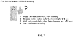
- FIG. 7 A one button camera for video recording is illustrated in FIG. 7 and shows four steps.
- step 2 if there is no step3 following, camera will generate short video (assume no one will hold very long time). Therefore, press & hold then release shutter button is defined as short video recording method.
- short video recording method For continuous recording method is defined as a quick click shutter button following by step 2. The continuous video recording will not stop till the shutter button being clicked again.
Landscapes
- Engineering & Computer Science (AREA)
- Multimedia (AREA)
- Signal Processing (AREA)
- General Engineering & Computer Science (AREA)
- Theoretical Computer Science (AREA)
- Human Computer Interaction (AREA)
- Physics & Mathematics (AREA)
- General Physics & Mathematics (AREA)
- Studio Devices (AREA)
Description
- The invention relates to a manipulation method. More particularly, the invention relates to a manipulation method of selecting between different functional modes according to a manipulation input.
- In order to increase mobility of electronic devices, designers are challenged to figure out how to reduce sizes and weights of the electronic devices. On a portable device, the size is a critical issue for the designer. A portable device (e.g., smart phones, digital cameras, sports cameras, tablets, or similar handheld devices) has less space for disposing buttons for different functions.
- If the portable device has ten different functions and each of the functions requires an individual button to manipulate (e.g., trigger, control, configure, etc), the portable device must has at least ten individual buttons. In this case, each of the ten buttons will be small, hard to locate and easy to be damaged. On the other hand, the size of the portable device must be enlarged for accommodating these buttons. It is a dilemma between increasing the mobility or the manoeuvrability of the portable device. However, the cutting-edge portable device must be capable to fulfil many functions within a compact size.
-
US 2014/055633 A1 ,EP 1 725 024US 2001/026263 A1 ,EP 2 897 355 A1US 2005/093988 A1 ,JP 2007 142715 GB 2 508341 AWO 2011/053058 may be regarded as background art useful for understanding the invention. - It is an object of the present disclosure to provide a portable device and a manipulation method therefore. This object can be achieved by the features as defined in the independent claims. Further enhancements are characterised by the dependent claims. It is an object of an embodiment of the present invention to provide a portable device, which is capable of performing multiple functions with a multi-purpose input sensor (e.g., button, key, switch, etc). The manipulation input sensed by the input sensor is analyzed and configured for triggering different functions of the portable device.
- In at least one embodiment the portable device includes a camera unit, a first sensor and a control module. The camera unit has a plurality of functional modes. The functional modes include a photo-capturing mode and a video-recording mode. The first sensor is disposed on the portable device and configured for sensing a manipulation input. The manipulation input has a manipulation pattern and duration information of aforesaid manipulation pattern. The control module is coupled with the camera unit and the first sensor. The control module is configured for selecting one of the functional modes corresponding to the manipulation pattern and the duration information sensed by the first sensor, and triggering the camera unit into the selected functional mode.
- At least one embodiment of the disclosure provides a manipulation method, which is suitable for the portable device includes a camera unit. The camera unit has a plurality of functional modes including a photo-capturing mode and a video-recording mode. The manipulation method includes steps of: sensing a manipulation input; extracting a manipulation pattern and duration information of aforesaid manipulation pattern from the manipulation input; selecting one of the functional modes corresponding to the manipulation pattern according to the manipulation pattern and the duration information; and, triggering the camera unit into the selected functional mode.
- Another aspect of the disclosure is to provide a non-transitory computer readable storage medium with a computer program to execute aforesaid manipulation method.
- Aspects of the disclosure are best understood from the following detailed description when read with the accompanying figures. It is noted that, in accordance with the standard practice in the industry, various features are not drawn to scale. In fact, the dimensions of the various features may be arbitrarily increased or reduced for clarity of discussion. The accompanying drawings illustrate presently exemplary embodiments of the disclosure and serve to explain, by way of example, the principles of the disclosure.
-
FIG. 1 is a schematic diagram illustrating aportable device 100 according to an embodiment of this disclosure. -
FIG. 2 to FIG. 5 are schematic diagrams illustrating the manipulation input sensed by the first sensor in four different examples according to the embodiment. -
FIG. 6 is a flow chart diagram illustrating a manipulation method according to an embodiment of the disclosure. -
FIG. 7 is an exemplary one button camera for video recording. - The following disclosure provides many different embodiments, or examples, for implementing different features of the invention. Specific examples of components and arrangements are described below to simplify the present disclosure. These are, of course, merely examples and are not intended to be limiting. In addition, the present disclosure may repeat reference numerals and/or letters in the various examples. This repetition is for the purpose of simplicity and clarity and does not in itself dictate a relationship between the various embodiments and/or configurations discussed.
-
FIG. 1 is a schematic diagram illustrating aportable device 100 according to an embodiment of this disclosure. As shown inFIG. 1 , theportable device 100 includes acamera unit 120, afirst sensor 140 and acontrol module 160. In practices, theportable device 100 can be a sports camera, a versatile camera, a smart phone, a digital camera, a tablet, or a similar handheld device. - In practical applications, the
camera unit 120 of theportable device 100 includes lens, an optical sensor component, a focusing motor and/or a digital signal processor (DSP) for processing an image or a video captured by thecamera unit 120. Aforesaid structures of thecamera unit 120 is well known by a person in the art and not further discussed here. - In the embodiment, the
camera unit 120 has several functional modes. The functional modes at least include a photo-capturing mode and a video-recording mode. When thecamera unit 120 is operated under the photo-capturing mode, thecamera unit 120 is able to capture a photograph in response to a photo-shooting command (e.g., a manipulation input from a user). When thecamera unit 120 is operated under the video-recording mode, thecamera unit 120 is able to record a video in response to a video-recording command (e.g., another manipulation input from the user). Furthermore, thecamera unit 120 is not limited to aforesaid two functional modes. For example, thecamera unit 120 may further have a burst-capturing mode, which is utilized to capture a series of photographs in sequence; and, thecamera unit 120 may further have a broadcasting mode, which is utilized to live broadcasting a streaming video recorded by thecamera unit 120. In some embodiments, theportable device 100 further includes acommunication unit 180 for exchanging information with at least one external terminal (e.g., a server of Youtube, Twitch, HTC ZOE, or any equivalent streaming video terminal). The streaming video recorded by thecamera unit 120 can be transmitted to the external terminal. - On a conventional device, there might be different buttons (e.g., a shutter button and a recording button) for generating the single-shooting command and the video-recording command individually. However, it is hard to find enough space to dispose all these buttons on the
portable device 100 for each of the functions. - In some embodiment, the
first sensor 140 is a switch button disposed on theportable device 100. The switch button can be manipulated by the user (e.g., click, double click, press down, press and hold, etc.). Based on how the user manipulates the switch button, thefirst sensor 140 will generate a corresponding manipulation input. Thefirst sensor 140 is utilized to generate different commands (e.g., the photo-shooting command, the video-recording command, etc.), for triggering thecamera unit 120 into different functional modes with only one switch button. - The manipulation input generated by the
first sensor 140 has a manipulation pattern and duration information of aforesaid manipulation pattern. In this embodiment, the manipulation pattern is related to a behavior, a count, a distribution about how the user manipulates the switch button (e.g., the user clicks the switch button once, the user clicks the switch button several times in a row, the user presses the switch button down and holds the switch button). The duration information of the manipulation pattern is related to how long the switch button has been pressed down. In some embodiments, the duration information is counted separately for each time the switch button is pressed. - The
control module 160 is coupled with thecamera unit 120 and thefirst sensor 140. Thecontrol module 160 is configured for selecting one of the functional modes corresponding to the manipulation pattern and the duration information sensed by the first sensor, and triggering the camera unit into the selected functional mode. In practices, thecontrol module 160 is a processor, a central processing unit, a control integrated chip, or a System-on-Chip (SoC) for executing some programs/instructions, performing computations and/or managing some processes of theportable device 100. - In some embodiments, the
portable device 100 further includes asecond sensor 142. Thesecond sensor 142 is disposed on theportable device 100. In some embodiments, thesecond sensor 142 is a pressure sensor and configured for sensing a pressure value on a surface of theportable device 100. Thecontrol module 160 is further coupled with thesecond sensor 142 and configured for determining whether theportable device 100 is gripped by the user. Thefirst sensor 140 is deactivated in response to theportable device 100 is not gripped by the user. -
FIG. 2 to FIG. 5 are schematic diagrams illustrating the manipulation input MP1/MP2/MP3/MP4 sensed by thefirst sensor 140 in four different examples according to the embodiment. - As shown in
FIG. 2 , thefirst sensor 120 generates the manipulation input MP1, which indicates that the switch button is pressed down (at the time point T1a) and then released (at the time point T2a) within a first predetermined duration PD1. The first predetermined duration is utilized as a reference to identify the manipulation pattern of the manipulation input MP1∼MP4. The first predetermined duration PD1 in the example is about 1 second for demonstration, but the first predetermined duration PD1 is not limited to 1 second. - The press-and-hold duration D1 between the time points T1a and T2a is shorter than the first predetermined duration PD1. Therefore, the manipulation pattern of the manipulation input MP1 corresponding to the press-and-hold duration D1 is regarded as a "click" pattern. In this case, the photo-capturing mode is selected by the
control module 160, and thecamera unit 120 is triggered to capture a photo PHO1 corresponding to the press-and-hold duration D1. For example, the photo PHO1 can be pre-captured at time point T1 a (at the moment when the switch button is just pressed), or the photo PHO1 can be captured at time point T2a (right after the switch button is just released). - As shown in
FIG. 2 , the switch button is pressed down again (at the time point T3a) and then released again (at the time point T4a) within the first predetermined duration PD1. The press-and-hold duration D2 between the time points T3a and T4a is also shorter than the first predetermined duration PD1. Therefore, the manipulation pattern of the manipulation input MP1 corresponding to the press-and-hold duration D2 is also regarded as another "click" pattern. In this case, the photo-capturing mode is selected by thecontrol module 160, and thecamera unit 120 is triggered to capture another photo PHO2 corresponding to the press-and-hold duration D2. For example, the photo PHO2 can be captured at time point T3a or T4a. - Afterward, the switch button is pressed down again (at the time point T5a) and then released again (at the time point T6a) within the first predetermined duration PD1. The manipulation pattern of the manipulation input MP1 corresponding to the press-and-hold duration D3 (between T5a and T6a) is also regarded as another "click" pattern. In this case, the photo-capturing mode is selected by the
control module 160, and thecamera unit 120 is triggered to capture another photo corresponding to the press-and-hold duration D3. For example, the photo PHO3 can be captured at time point T5a or T6a. - In summary, if the manipulation input MP1 includes any press-and-hold duration D1/D2/D3 shorter than the first predetermined duration PD1, the press-and-hold duration D1/D2/D3 will be viewed as a "click" pattern. In response to one "click" pattern, the
camera unit 120 is triggered to capture one photo PHO1/PHO2/PHO3 - On the other hand, if the switch button is pressed and held over the first predetermined duration PD1, the video-recording mode is selected by the
control module 140, and thecamera unit 120 is triggered into the video-recording mode for recording a video VDO1 in response to the manipulation input. As the embodiment shown inFIG. 3 , thefirst sensor 120 generates the manipulation input MP2, which indicates that the switch button is pressed down (at the time point T1 b), held over the first predetermined duration PD1, and then released (at the time point T3b) within a second predetermined duration PD2. The second predetermined duration PD2 is longer than the first predetermined duration PD1. The second predetermined duration PD2 is also utilized as a reference to identify the manipulation pattern of the manipulation input MP1∼MP4. The second predetermined duration PD2 in the example is about 3 seconds for demonstration, and not limited to 3 seconds. - The press-and-hold duration D4 between the time points T1b and T3b is longer than the first predetermined duration PD1 and shorter than the second predetermined duration PD2. The manipulation pattern of the manipulation input MP2 corresponding to the press-and-hold duration D4 is regarded as a "short-press" pattern. In this case, the video-recording mode is selected by the
control module 160, and thecamera unit 120 is triggered to record the video VDO1 started from the time point T2b (at the moment when the switch button is pressed and held after the predetermined duration PD1). The video-recording mode of thecamera unit 120 is stopped when the switch button is released (at the time point T3b). In some embodiments, based on the manipulation input MP2, a photo PHO4 is captured by thecamera unit 120 at the time point T1 b in addition to the video VDO1. - As the embodiment shown in
FIG. 4 , thefirst sensor 120 generates the manipulation input MP3, which indicates that the switch button is pressed down (at the time point T1c), held over the first predetermined duration PD1 and the second predetermined duration PD2, and then released at the time point T3c. - The press-and-hold duration D5 between the time points T1c and T3c is longer than the first predetermined duration PD1 and the second predetermined duration PD2. The manipulation pattern of the manipulation input MP3 corresponding to the press-and-hold duration D5 is regarded as a "long-press" pattern. In this case, the video-recording mode is selected by the
control module 160, and thecamera unit 120 is triggered to record the video VDO2 started from the time point T2b (at the moment when the switch button is pressed and held after the predetermined duration PD1). Thecamera unit 120 is locked (e.g., continuously operated) in the video-recording mode and keeps on recording the video VDO2. - In addition, the manipulation input MP3 further indicates that the switch button is pressed down (at the time point T4c) and released within the first predetermined duration PD1 (at the time point T5c). The press-and-hold duration D6 between the time points T4c and T5c is shorter than the first predetermined duration PD1. The manipulation pattern of the manipulation input MP3 corresponding to the press-and-hold duration D6 is regarded as a "click" pattern. In the embodiment show in
FIG. 4 , the video-recording mode of thecamera unit 120 is stopped when the switch button is released (at the time point T5c) corresponding to the "click" pattern. - In other words, the "long-press" pattern of the manipulation input MP3 is configured to trigger the
camera unit 120 into the video-recording mode, and thecamera unit 120 is locked in the video-recording mode until the "click" pattern of the manipulation input MP3. In some embodiments, based on the manipulation input MP3, a photo PHO5 is captured by thecamera unit 120 at the time point T1c in addition to the video VDO2. - As the embodiment shown in
FIG. 5 , thefirst sensor 120 generates the manipulation input MP4, which indicates that the switch button is pressed down (at the time point T1d), held over the first predetermined duration PD1 and the second predetermined duration PD2, and then released at the time point T3d. - The press-and-hold duration D7 between the time points T1d and T3d is longer than the first predetermined duration PD1 and the second predetermined duration PD2. The manipulation pattern of the manipulation input MP4 corresponding to the press-and-hold duration D7 is regarded as a "long-press" pattern. In this case, the video-recording mode is selected by the
control module 160, and thecamera unit 120 is triggered to record the video VDO3 started from the time point T2d (at the moment when the switch button is pressed and held after the predetermined duration PD1). Thecamera unit 120 is locked in the video-recording mode and keeps on recording the video VDO3. - In addition, the manipulation input MP4 further indicates that the switch button is pressed down (at the time point T4d) and held over the first predetermined duration PD1. The press-and-hold duration D8 between the time points T4d and T6d is longer than the first predetermined duration PD1 and regarded as a "short-press" pattern. In the embodiment show in
FIG. 5 , thecamera unit 120 is triggered into a broadcasting mode and theportable device 100 broadcasts a streaming video SVDO currently recorded by the camera unit 120 (started from the time point T5d). The streaming video SVDO is transmitted to the at least one external terminal (a server of Youtube, Twitch, HTC ZOE, or any equivalent streaming video terminal) through thecommunication unit 180. - Aforesaid embodiments shown in
FIG. 2, FIG. 3, FIG. 4 and FIG. 5 demonstrate an example about how to activate/trigger multiple functions (including a photo-capturing, a video-recording, a stream-broadcasting, etc) with one switch button (i.e., the first sensor 140). However, this disclosure is not limited to the relationship between the manipulation patterns and the functions as the embodiments shown inFIG. 2 to FIG. 5 , and any equivalent configurations are also possible to manipulate even more functions with one switch buttons according to different manipulation patterns (a combination of click, double click, soft press, hard press, short press and/or long press). -
FIG. 6 is a flow chart diagram illustrating amanipulation method 300 according to an embodiment of the disclosure. Themanipulation method 300 is suitable to be utilized on theportable device 100 as disclosed in aforesaid embodiments. - As shown in
FIG. 6 , themanipulation method 300 executes step S304 for sensing a manipulation input (by thefirst sensor 140 shown inFIG. 1 ). Step S305 is executed for extracting a manipulation pattern and duration information of the manipulation pattern from the manipulation input. Step S306 is executed for selecting one of the functional modes corresponding to the manipulation pattern according to the manipulation pattern and the duration information. Details about the manipulation pattern, the duration information and how to select the functional mode accordingly (about steps S306 and S307) are disclosed in aforesaid embodiments and examples related toFIG. 2 to FIG. 5 . Therefore, it is not repeated here. Step S307 is executed for triggering thecamera unit 120 into the selected functional mode. - As shown in
FIG. 6 , before steps S304-S307, themanipulation method 300 further executes step S301 for sensing a pressure value on a surface of the portable device (by thesecond sensor 142 as shown inFIG. 1 ). Step S302 is executed for determining whether the portable device is gripped according to the pressure value. If the pressure value indicated that the portable device is gripped by the user, then step S304 is activated to sense the manipulation input by thefirst sensor 140. On the other hand, if the pressure value indicated that the portable device is not gripped by the user, step S303 is executed for suspending from sensing the manipulation input in response to theportable device 100 is not gripped. Therefore, theportable device 100 is configured into a standby mode when theportable device 100 is not gripped by the user, and thefirst sensor 140 is suspended from updating the sensing result of the manipulation input, so as to reduce the power consumption of thefirst sensor 140. Only when theportable device 100 is gripped by the user, thefirst sensor 140 is activated to provide the manipulation input. - Another embodiment of the disclosure is to provide a non-transitory computer readable storage medium with a computer program to execute
aforesaid manipulation method 300 as shown inFIG. 6 . - Based on aforesaid embodiments, this disclosure is to provide a portable device, a manipulation method and a non-transitory computer readable storage medium, which are capable of performing multiple functions with a multi-purpose input sensor (e.g., button, key, switch, etc). The manipulation input sensed by the input sensor is analyzed and configured for triggering different functions of the portable device. Therefore, the portable device is able to perform as many functions as possible with fewer switch buttons or functional keys, such that the portable device can be light weighted and compact sized without cutting off functions.
- In this document, the term "coupled" may also be termed as "electrically coupled", and the term "connected" may be termed as "electrically connected". "Coupled" and "connected" may also be used to indicate that two or more elements cooperate or interact with each other. It will be understood that, although the terms "first," "second," etc., may be used herein to describe various elements, these elements should not be limited by these terms. These terms are used to distinguish one element from another. For example, a first element could be termed a second element, and, similarly, a second element could be termed a first element, without departing from the scope of the embodiments. As used herein, the term "and/or" includes any and all combinations of one or more of the associated listed items.
- It will be apparent to those skilled in the art that various modifications and variations may be made to the structure of the disclosed embodiments without departing from the scope of the disclosure.
- An embodiment may be a one button camera for video recording.
Photo mode Short Press Video mode (Option A) Short Video mode Press&Hold: Start Release: Stop Long Video mode (Option 2) Double click: Start Press again: stop Long Video mode (Option 3) Press&Hold: Start Release and press again: Lock video recording Press again: stop Video mode (Option B) Press&Hold: Start recording Release within the defined period of time: stop recording Otherwise will lock video recording until press again - For a single button camera, usually defines the trigger for photo capturing as single tap, defines the trigger for video recording as press & hold. However the definition of stop for video recording might confuse users like: stop when finger release the button or stop when the user presses the button again.
- The invention propose a new behavior which will record few more seconds (ex., 3-5 sec) then stop when release button case, and if the user press again in very short period (ex., <1 sec and this can be indicated by led status), it will interpret the user's intention is to keep recording, then the video recording can continue.
- A one button camera for video recording is illustrated in
FIG. 7 and shows four steps. - 1. Press & hold shutter button, start recording
- 2. Release shutter button, buffer the recording for 3-5 sec
- 3. Click button again before Led flash disappear (ex., <0.5 sec)
- 4. Start continuous recording
- At
step 2, if there is no step3 following, camera will generate short video (assume no one will hold very long time). Therefore, press & hold then release shutter button is defined as short video recording method. For continuous recording method is defined as a quick click shutter button following bystep 2. The continuous video recording will not stop till the shutter button being clicked again.
Claims (7)
- A portable device, comprising:a camera unit (120) having a plurality of functional modes, the functional modes comprising a photo-capturing mode and a video-recording mode;a first sensor (140), disposed on the portable device and configured for sensing a manipulation input, the manipulation input having a manipulation pattern and duration information of the manipulation pattern, wherein the first sensor is a switch button;a control module (160), coupled with the camera unit (120) and the first sensor (140), the control module (160) being configured for selecting one of the functional modes corresponding to the manipulation pattern and press and hold duration information sensed by the first sensor (140), and triggering the camera unit (120) into the selected functional mode,wherein in response to the manipulation pattern of the switch button comprising the switch button is pressed and then released within a first predetermined duration, the photo-capturing mode is selected by the control module, and the camera unit is triggered to capture one photo at the time instant of pressing or releasing the switch button,wherein in response to a manipulation pattern of the switch button comprising the switch button is pressed and held over the first predetermined duration, the video-recording mode is selected by the control module, and the camera unit is triggered to start capturing a video at the end of the first predetermined duration,the portable device being characterised in thatin response to the switch button being released within a second predetermined period after pressing and holding the switch button over a first predetermined duration for selecting the video-recoding mode, the camera unit is triggered to stop the video-recording mode, the first and second predetermined period being initiated at the same time instant and the second predetermined duration being longer than the first predetermined duration; andin response to the manipulation pattern of the switch button comprising: the switch button is pressed, held over the first predetermined duration and released after the second predetermined duration, the camera unit (120) is locked in the video-recording mode by the control module until the switch button is pressed again and then released within a first predetermined duration.
- The portable device of claim 1, further comprising:a second sensor (142), disposed on the portable device and configured for sensing a pressure value on a surface of the portable device,wherein the control module is further coupled with the second sensor (142) and configured for determining whether the portable device is gripped, the first sensor is deactivated in response to the portable device is not gripped.
- The portable device of claim 1, wherein the portable device further comprises a communication unit for exchanging information with at least one external terminal, the functional modes further comprises a broadcasting mode, while the camera unit is locked in the video-recording mode, in response to the switch button is pressed again and held over a first predetermined duration, the camera unit is triggered into the broadcasting mode and the portable device broadcasts a streaming video currently recorded by the camera unit to the at least one external terminal through the communication unit.
- A manipulation method, suitable for the portable device comprising a camera unit (120), the camera unit having a plurality of functional modes comprising a photo-capturing mode and a video-recording mode, the manipulation method comprising:sensing a manipulation input by a switch button;extracting a manipulation pattern and duration information of the manipulation pattern from the manipulation input;selecting one of the functional modes corresponding to the manipulation pattern according to the manipulation pattern and press and hold duration information;triggering the camera unit into the selected functional mode;in response to the manipulation pattern of the switch button comprising the switch button is pressed and then released within the first predetermined duration, selecting the photo-capturing mode by the control module, and triggering the camera unit to capture one photo at the time instant of pressing or releasing the switch button; andin response to the manipulation pattern of the switch button comprising the switch button is pressed and held over the first predetermined duration, selecting the video-recording mode by the control module, and triggering the camera unit to start the video-recording mode at the end of the first predetermined duration;the manipulation method being characterised byin response to the switch button is pressed and held over the first predetermined duration and released within a second predetermined duration for selecting the video-recoding mode, terminating the video-recording mode when the switch button is released, the first and second predetermined period being initiated at the same time instant and the second predetermined duration being longer than the first predetermined duration; andin response to the manipulation pattern of the switch button comprising the switch button is pressed, held over the first predetermined duration and released after the second predetermined duration, locking the camera unit in the video-recording mode by the control module until the switch button is pressed again and then released within a first predetermined duration.
- The manipulation method of claim 4, further comprising:sensing a pressure value on a surface of the portable device;determining whether the portable device is gripped according to the pressure value; andsuspending from sensing the manipulation input in response to the portable device is not gripped.
- The manipulation method of claim 4, wherein the functional modes further comprises a broadcasting mode, while the camera unit is locked in the video-recording mode, in response to the switch button is pressed again and held over a first predetermined duration, the manipulation method further comprising:triggering the camera unit into the broadcasting mode;broadcasting a streaming video currently recorded by the camera unit to at least one external terminal.
- A non-transitory computer readable storage medium for a portable device comprising a camera unit (120), a first sensor (140) for sensing a manipulation pattern and a control module (160) coupled with the camera unit and the first sensor, the non-transitory computer readable storage medium storing instructions that, when executed by control module (160), cause the portable device to perform all the steps of the manipulation method according to any one of the claims 4 to 6.
Applications Claiming Priority (2)
| Application Number | Priority Date | Filing Date | Title |
|---|---|---|---|
| US201462009338P | 2014-06-09 | 2014-06-09 | |
| US14/720,842 US9648237B2 (en) | 2014-06-09 | 2015-05-25 | Portable device and manipulation method for triggering different functions with a manipulation input |
Publications (2)
| Publication Number | Publication Date |
|---|---|
| EP2955912A1 EP2955912A1 (en) | 2015-12-16 |
| EP2955912B1 true EP2955912B1 (en) | 2018-02-21 |
Family
ID=53489780
Family Applications (1)
| Application Number | Title | Priority Date | Filing Date |
|---|---|---|---|
| EP15169540.0A Active EP2955912B1 (en) | 2014-06-09 | 2015-05-28 | Portable device and manipulation method for triggering different functions with a manipulation input |
Country Status (2)
| Country | Link |
|---|---|
| US (1) | US9648237B2 (en) |
| EP (1) | EP2955912B1 (en) |
Families Citing this family (3)
| Publication number | Priority date | Publication date | Assignee | Title |
|---|---|---|---|---|
| US9489671B2 (en) * | 2002-10-01 | 2016-11-08 | Andrew H B Zhou | Systems and methods for mobile application, wearable application, transactional messaging, calling, digital multimedia capture and payment transactions |
| WO2016209984A1 (en) * | 2015-06-22 | 2016-12-29 | Super 6 LLC | Mobile device videography system |
| JP7565183B2 (en) * | 2020-10-12 | 2024-10-10 | ヤンマーホールディングス株式会社 | Work vehicles |
Citations (2)
| Publication number | Priority date | Publication date | Assignee | Title |
|---|---|---|---|---|
| WO2011053058A2 (en) * | 2009-10-30 | 2011-05-05 | Samsung Electronics Co., Ltd. | Mobile device and method for providing user interface (ui) thereof |
| GB2508341A (en) * | 2012-11-27 | 2014-06-04 | Samsung Electronics Uk Ltd | Capturing images using a predetermined motion to activate a button |
Family Cites Families (9)
| Publication number | Priority date | Publication date | Assignee | Title |
|---|---|---|---|---|
| US7319490B2 (en) * | 2000-01-21 | 2008-01-15 | Fujifilm Corporation | Input switch with display and image capturing apparatus using the same |
| US20050093988A1 (en) * | 2003-11-03 | 2005-05-05 | Haas William R. | Digital camera with automatic mode detection |
| JP4505740B2 (en) | 2005-05-16 | 2010-07-21 | ソニー株式会社 | Imaging apparatus and method for starting the same |
| JP4682382B2 (en) * | 2005-11-17 | 2011-05-11 | 株式会社メガチップス | Imaging device |
| TW201005503A (en) * | 2008-07-16 | 2010-02-01 | Htc Corp | Portable electronic device and the mode switching method thereof |
| KR101642400B1 (en) * | 2009-12-03 | 2016-07-25 | 삼성전자주식회사 | Digital photographing apparatus, method for controlling the same, and recording medium storing program to execute the method |
| US20140055633A1 (en) | 2012-08-27 | 2014-02-27 | Richard E. MARLIN | Device and method for photo and video capture |
| KR102003377B1 (en) * | 2012-12-13 | 2019-07-24 | 삼성전자주식회사 | Apparatas and method for driving a camera module of sleep mode in an electronic device |
| CN104796599B (en) * | 2014-01-17 | 2019-01-01 | 宏达国际电子股份有限公司 | Electronic device with switch button and control method thereof |
-
2015
- 2015-05-25 US US14/720,842 patent/US9648237B2/en active Active
- 2015-05-28 EP EP15169540.0A patent/EP2955912B1/en active Active
Patent Citations (2)
| Publication number | Priority date | Publication date | Assignee | Title |
|---|---|---|---|---|
| WO2011053058A2 (en) * | 2009-10-30 | 2011-05-05 | Samsung Electronics Co., Ltd. | Mobile device and method for providing user interface (ui) thereof |
| GB2508341A (en) * | 2012-11-27 | 2014-06-04 | Samsung Electronics Uk Ltd | Capturing images using a predetermined motion to activate a button |
Also Published As
| Publication number | Publication date |
|---|---|
| US20150358541A1 (en) | 2015-12-10 |
| EP2955912A1 (en) | 2015-12-16 |
| US9648237B2 (en) | 2017-05-09 |
Similar Documents
| Publication | Publication Date | Title |
|---|---|---|
| US10291847B2 (en) | Portable device and manipulation method | |
| US9578239B2 (en) | Controlling method for electronic apparatus with one switch button | |
| CN103108127A (en) | Method for shooting pictures through portable device and portable device | |
| CN105159726A (en) | A method and device for quickly starting to take pictures | |
| CN105117137A (en) | A method and device for taking pictures when a terminal is in standby, and a mobile terminal | |
| TWI438715B (en) | Image processing methods and systems for handheld devices, and computer program products thereof | |
| CN105302432B (en) | Portable device and operation method | |
| EP2765482A1 (en) | Handheld electronic apparatus and operation method thereof | |
| EP2955912A1 (en) | Portable device and manipulation method for triggering different functions with a manipulation input | |
| CN105117135A (en) | A camera method and device when a terminal is in standby | |
| US11137666B2 (en) | Control device and control method | |
| CN106095422B (en) | Application control method and device and terminal equipment | |
| US20150022704A1 (en) | Orientation-Based Camera Operation | |
| US20170090623A1 (en) | Electronic apparatus and operating method of electronic apparatus | |
| US9621809B2 (en) | Display control apparatus and method for controlling the same | |
| US9521313B2 (en) | Image capturing control apparatus, image capturing control method, and computer program | |
| US20140111453A1 (en) | Selective locking method of information device having touch screen | |
| US8866921B2 (en) | Devices and methods involving enhanced resolution image capture | |
| CN112148185A (en) | Image display method and device | |
| US9106820B1 (en) | Multi-stage trigger for capturing video images | |
| KR20130080932A (en) | Method and apparatus for storing image of camera | |
| CN106527907A (en) | Screen capturing processing method and device for smart terminal | |
| CN105791670A (en) | Image acquisition method and device | |
| US9756238B2 (en) | Image capturing apparatus for performing authentication of a photographer and organizing image data for each photographer and control method thereof | |
| CN113419640A (en) | Pressure sensing channel opening method and device and electronic equipment |
Legal Events
| Date | Code | Title | Description |
|---|---|---|---|
| PUAI | Public reference made under article 153(3) epc to a published international application that has entered the european phase |
Free format text: ORIGINAL CODE: 0009012 |
|
| 17P | Request for examination filed |
Effective date: 20150528 |
|
| AK | Designated contracting states |
Kind code of ref document: A1 Designated state(s): AL AT BE BG CH CY CZ DE DK EE ES FI FR GB GR HR HU IE IS IT LI LT LU LV MC MK MT NL NO PL PT RO RS SE SI SK SM TR |
|
| AX | Request for extension of the european patent |
Extension state: BA ME |
|
| RBV | Designated contracting states (corrected) |
Designated state(s): AL AT BE BG CH CY CZ DE DK EE ES FI FR GB GR HR HU IE IS IT LI LT LU LV MC MK MT NL NO PL PT RO RS SE SI SK SM TR |
|
| 17Q | First examination report despatched |
Effective date: 20161007 |
|
| STAA | Information on the status of an ep patent application or granted ep patent |
Free format text: STATUS: EXAMINATION IS IN PROGRESS |
|
| GRAP | Despatch of communication of intention to grant a patent |
Free format text: ORIGINAL CODE: EPIDOSNIGR1 |
|
| STAA | Information on the status of an ep patent application or granted ep patent |
Free format text: STATUS: GRANT OF PATENT IS INTENDED |
|
| INTG | Intention to grant announced |
Effective date: 20171020 |
|
| GRAJ | Information related to disapproval of communication of intention to grant by the applicant or resumption of examination proceedings by the epo deleted |
Free format text: ORIGINAL CODE: EPIDOSDIGR1 |
|
| STAA | Information on the status of an ep patent application or granted ep patent |
Free format text: STATUS: EXAMINATION IS IN PROGRESS |
|
| GRAR | Information related to intention to grant a patent recorded |
Free format text: ORIGINAL CODE: EPIDOSNIGR71 |
|
| GRAS | Grant fee paid |
Free format text: ORIGINAL CODE: EPIDOSNIGR3 |
|
| STAA | Information on the status of an ep patent application or granted ep patent |
Free format text: STATUS: GRANT OF PATENT IS INTENDED |
|
| GRAA | (expected) grant |
Free format text: ORIGINAL CODE: 0009210 |
|
| STAA | Information on the status of an ep patent application or granted ep patent |
Free format text: STATUS: THE PATENT HAS BEEN GRANTED |
|
| INTC | Intention to grant announced (deleted) | ||
| AK | Designated contracting states |
Kind code of ref document: B1 Designated state(s): AL AT BE BG CH CY CZ DE DK EE ES FI FR GB GR HR HU IE IS IT LI LT LU LV MC MK MT NL NO PL PT RO RS SE SI SK SM TR |
|
| INTG | Intention to grant announced |
Effective date: 20180112 |
|
| REG | Reference to a national code |
Ref country code: GB Ref legal event code: FG4D |
|
| REG | Reference to a national code |
Ref country code: CH Ref legal event code: EP |
|
| REG | Reference to a national code |
Ref country code: AT Ref legal event code: REF Ref document number: 972929 Country of ref document: AT Kind code of ref document: T Effective date: 20180315 |
|
| REG | Reference to a national code |
Ref country code: IE Ref legal event code: FG4D |
|
| REG | Reference to a national code |
Ref country code: DE Ref legal event code: R096 Ref document number: 602015008107 Country of ref document: DE |
|
| REG | Reference to a national code |
Ref country code: FR Ref legal event code: PLFP Year of fee payment: 4 |
|
| REG | Reference to a national code |
Ref country code: NL Ref legal event code: FP |
|
| REG | Reference to a national code |
Ref country code: LT Ref legal event code: MG4D |
|
| REG | Reference to a national code |
Ref country code: AT Ref legal event code: MK05 Ref document number: 972929 Country of ref document: AT Kind code of ref document: T Effective date: 20180221 |
|
| PG25 | Lapsed in a contracting state [announced via postgrant information from national office to epo] |
Ref country code: CY Free format text: LAPSE BECAUSE OF FAILURE TO SUBMIT A TRANSLATION OF THE DESCRIPTION OR TO PAY THE FEE WITHIN THE PRESCRIBED TIME-LIMIT Effective date: 20180221 Ref country code: LT Free format text: LAPSE BECAUSE OF FAILURE TO SUBMIT A TRANSLATION OF THE DESCRIPTION OR TO PAY THE FEE WITHIN THE PRESCRIBED TIME-LIMIT Effective date: 20180221 Ref country code: HR Free format text: LAPSE BECAUSE OF FAILURE TO SUBMIT A TRANSLATION OF THE DESCRIPTION OR TO PAY THE FEE WITHIN THE PRESCRIBED TIME-LIMIT Effective date: 20180221 Ref country code: FI Free format text: LAPSE BECAUSE OF FAILURE TO SUBMIT A TRANSLATION OF THE DESCRIPTION OR TO PAY THE FEE WITHIN THE PRESCRIBED TIME-LIMIT Effective date: 20180221 Ref country code: NO Free format text: LAPSE BECAUSE OF FAILURE TO SUBMIT A TRANSLATION OF THE DESCRIPTION OR TO PAY THE FEE WITHIN THE PRESCRIBED TIME-LIMIT Effective date: 20180521 Ref country code: ES Free format text: LAPSE BECAUSE OF FAILURE TO SUBMIT A TRANSLATION OF THE DESCRIPTION OR TO PAY THE FEE WITHIN THE PRESCRIBED TIME-LIMIT Effective date: 20180221 |
|
| PG25 | Lapsed in a contracting state [announced via postgrant information from national office to epo] |
Ref country code: AT Free format text: LAPSE BECAUSE OF FAILURE TO SUBMIT A TRANSLATION OF THE DESCRIPTION OR TO PAY THE FEE WITHIN THE PRESCRIBED TIME-LIMIT Effective date: 20180221 Ref country code: RS Free format text: LAPSE BECAUSE OF FAILURE TO SUBMIT A TRANSLATION OF THE DESCRIPTION OR TO PAY THE FEE WITHIN THE PRESCRIBED TIME-LIMIT Effective date: 20180221 Ref country code: GR Free format text: LAPSE BECAUSE OF FAILURE TO SUBMIT A TRANSLATION OF THE DESCRIPTION OR TO PAY THE FEE WITHIN THE PRESCRIBED TIME-LIMIT Effective date: 20180522 Ref country code: SE Free format text: LAPSE BECAUSE OF FAILURE TO SUBMIT A TRANSLATION OF THE DESCRIPTION OR TO PAY THE FEE WITHIN THE PRESCRIBED TIME-LIMIT Effective date: 20180221 Ref country code: LV Free format text: LAPSE BECAUSE OF FAILURE TO SUBMIT A TRANSLATION OF THE DESCRIPTION OR TO PAY THE FEE WITHIN THE PRESCRIBED TIME-LIMIT Effective date: 20180221 Ref country code: BG Free format text: LAPSE BECAUSE OF FAILURE TO SUBMIT A TRANSLATION OF THE DESCRIPTION OR TO PAY THE FEE WITHIN THE PRESCRIBED TIME-LIMIT Effective date: 20180521 |
|
| PG25 | Lapsed in a contracting state [announced via postgrant information from national office to epo] |
Ref country code: AL Free format text: LAPSE BECAUSE OF FAILURE TO SUBMIT A TRANSLATION OF THE DESCRIPTION OR TO PAY THE FEE WITHIN THE PRESCRIBED TIME-LIMIT Effective date: 20180221 Ref country code: EE Free format text: LAPSE BECAUSE OF FAILURE TO SUBMIT A TRANSLATION OF THE DESCRIPTION OR TO PAY THE FEE WITHIN THE PRESCRIBED TIME-LIMIT Effective date: 20180221 Ref country code: IT Free format text: LAPSE BECAUSE OF FAILURE TO SUBMIT A TRANSLATION OF THE DESCRIPTION OR TO PAY THE FEE WITHIN THE PRESCRIBED TIME-LIMIT Effective date: 20180221 Ref country code: RO Free format text: LAPSE BECAUSE OF FAILURE TO SUBMIT A TRANSLATION OF THE DESCRIPTION OR TO PAY THE FEE WITHIN THE PRESCRIBED TIME-LIMIT Effective date: 20180221 Ref country code: PL Free format text: LAPSE BECAUSE OF FAILURE TO SUBMIT A TRANSLATION OF THE DESCRIPTION OR TO PAY THE FEE WITHIN THE PRESCRIBED TIME-LIMIT Effective date: 20180221 |
|
| REG | Reference to a national code |
Ref country code: DE Ref legal event code: R097 Ref document number: 602015008107 Country of ref document: DE |
|
| PG25 | Lapsed in a contracting state [announced via postgrant information from national office to epo] |
Ref country code: SK Free format text: LAPSE BECAUSE OF FAILURE TO SUBMIT A TRANSLATION OF THE DESCRIPTION OR TO PAY THE FEE WITHIN THE PRESCRIBED TIME-LIMIT Effective date: 20180221 Ref country code: CZ Free format text: LAPSE BECAUSE OF FAILURE TO SUBMIT A TRANSLATION OF THE DESCRIPTION OR TO PAY THE FEE WITHIN THE PRESCRIBED TIME-LIMIT Effective date: 20180221 Ref country code: DK Free format text: LAPSE BECAUSE OF FAILURE TO SUBMIT A TRANSLATION OF THE DESCRIPTION OR TO PAY THE FEE WITHIN THE PRESCRIBED TIME-LIMIT Effective date: 20180221 Ref country code: SM Free format text: LAPSE BECAUSE OF FAILURE TO SUBMIT A TRANSLATION OF THE DESCRIPTION OR TO PAY THE FEE WITHIN THE PRESCRIBED TIME-LIMIT Effective date: 20180221 |
|
| REG | Reference to a national code |
Ref country code: CH Ref legal event code: PL |
|
| PLBE | No opposition filed within time limit |
Free format text: ORIGINAL CODE: 0009261 |
|
| STAA | Information on the status of an ep patent application or granted ep patent |
Free format text: STATUS: NO OPPOSITION FILED WITHIN TIME LIMIT |
|
| 26N | No opposition filed |
Effective date: 20181122 |
|
| REG | Reference to a national code |
Ref country code: BE Ref legal event code: MM Effective date: 20180531 |
|
| PG25 | Lapsed in a contracting state [announced via postgrant information from national office to epo] |
Ref country code: MC Free format text: LAPSE BECAUSE OF FAILURE TO SUBMIT A TRANSLATION OF THE DESCRIPTION OR TO PAY THE FEE WITHIN THE PRESCRIBED TIME-LIMIT Effective date: 20180221 |
|
| REG | Reference to a national code |
Ref country code: IE Ref legal event code: MM4A |
|
| PG25 | Lapsed in a contracting state [announced via postgrant information from national office to epo] |
Ref country code: SI Free format text: LAPSE BECAUSE OF FAILURE TO SUBMIT A TRANSLATION OF THE DESCRIPTION OR TO PAY THE FEE WITHIN THE PRESCRIBED TIME-LIMIT Effective date: 20180221 Ref country code: LI Free format text: LAPSE BECAUSE OF NON-PAYMENT OF DUE FEES Effective date: 20180531 Ref country code: CH Free format text: LAPSE BECAUSE OF NON-PAYMENT OF DUE FEES Effective date: 20180531 |
|
| PG25 | Lapsed in a contracting state [announced via postgrant information from national office to epo] |
Ref country code: LU Free format text: LAPSE BECAUSE OF NON-PAYMENT OF DUE FEES Effective date: 20180528 |
|
| PG25 | Lapsed in a contracting state [announced via postgrant information from national office to epo] |
Ref country code: IE Free format text: LAPSE BECAUSE OF NON-PAYMENT OF DUE FEES Effective date: 20180528 |
|
| PG25 | Lapsed in a contracting state [announced via postgrant information from national office to epo] |
Ref country code: BE Free format text: LAPSE BECAUSE OF NON-PAYMENT OF DUE FEES Effective date: 20180531 |
|
| PG25 | Lapsed in a contracting state [announced via postgrant information from national office to epo] |
Ref country code: MT Free format text: LAPSE BECAUSE OF NON-PAYMENT OF DUE FEES Effective date: 20180528 |
|
| PG25 | Lapsed in a contracting state [announced via postgrant information from national office to epo] |
Ref country code: TR Free format text: LAPSE BECAUSE OF FAILURE TO SUBMIT A TRANSLATION OF THE DESCRIPTION OR TO PAY THE FEE WITHIN THE PRESCRIBED TIME-LIMIT Effective date: 20180221 |
|
| PG25 | Lapsed in a contracting state [announced via postgrant information from national office to epo] |
Ref country code: PT Free format text: LAPSE BECAUSE OF FAILURE TO SUBMIT A TRANSLATION OF THE DESCRIPTION OR TO PAY THE FEE WITHIN THE PRESCRIBED TIME-LIMIT Effective date: 20180221 |
|
| PG25 | Lapsed in a contracting state [announced via postgrant information from national office to epo] |
Ref country code: HU Free format text: LAPSE BECAUSE OF FAILURE TO SUBMIT A TRANSLATION OF THE DESCRIPTION OR TO PAY THE FEE WITHIN THE PRESCRIBED TIME-LIMIT; INVALID AB INITIO Effective date: 20150528 Ref country code: MK Free format text: LAPSE BECAUSE OF NON-PAYMENT OF DUE FEES Effective date: 20180221 |
|
| PG25 | Lapsed in a contracting state [announced via postgrant information from national office to epo] |
Ref country code: IS Free format text: LAPSE BECAUSE OF FAILURE TO SUBMIT A TRANSLATION OF THE DESCRIPTION OR TO PAY THE FEE WITHIN THE PRESCRIBED TIME-LIMIT Effective date: 20180621 |
|
| REG | Reference to a national code |
Ref country code: DE Ref legal event code: R079 Ref document number: 602015008107 Country of ref document: DE Free format text: PREVIOUS MAIN CLASS: H04N0005232000 Ipc: H04N0023600000 |
|
| REG | Reference to a national code |
Ref country code: FR Ref legal event code: PLFP Year of fee payment: 9 |
|
| REG | Reference to a national code |
Ref country code: DE Ref legal event code: R082 Ref document number: 602015008107 Country of ref document: DE Representative=s name: WAGNER & GEYER PARTNERSCHAFT MBB PATENT- UND R, DE |
|
| P01 | Opt-out of the competence of the unified patent court (upc) registered |
Effective date: 20230602 |
|
| PGFP | Annual fee paid to national office [announced via postgrant information from national office to epo] |
Ref country code: NL Payment date: 20250409 Year of fee payment: 11 |
|
| PGFP | Annual fee paid to national office [announced via postgrant information from national office to epo] |
Ref country code: DE Payment date: 20250402 Year of fee payment: 11 |
|
| PGFP | Annual fee paid to national office [announced via postgrant information from national office to epo] |
Ref country code: GB Payment date: 20250401 Year of fee payment: 11 |
|
| PGFP | Annual fee paid to national office [announced via postgrant information from national office to epo] |
Ref country code: FR Payment date: 20250401 Year of fee payment: 11 |