EP2955877A1 - Point to multi-point ring network protection method and device - Google Patents
Point to multi-point ring network protection method and device Download PDFInfo
- Publication number
- EP2955877A1 EP2955877A1 EP14748908.2A EP14748908A EP2955877A1 EP 2955877 A1 EP2955877 A1 EP 2955877A1 EP 14748908 A EP14748908 A EP 14748908A EP 2955877 A1 EP2955877 A1 EP 2955877A1
- Authority
- EP
- European Patent Office
- Prior art keywords
- node
- data stream
- ring
- protection
- label
- Prior art date
- Legal status (The legal status is an assumption and is not a legal conclusion. Google has not performed a legal analysis and makes no representation as to the accuracy of the status listed.)
- Granted
Links
Images

Classifications
-
- H—ELECTRICITY
- H04—ELECTRIC COMMUNICATION TECHNIQUE
- H04L—TRANSMISSION OF DIGITAL INFORMATION, e.g. TELEGRAPHIC COMMUNICATION
- H04L12/00—Data switching networks
- H04L12/28—Data switching networks characterised by path configuration, e.g. LAN [Local Area Networks] or WAN [Wide Area Networks]
- H04L12/42—Loop networks
- H04L12/437—Ring fault isolation or reconfiguration
-
- H—ELECTRICITY
- H04—ELECTRIC COMMUNICATION TECHNIQUE
- H04L—TRANSMISSION OF DIGITAL INFORMATION, e.g. TELEGRAPHIC COMMUNICATION
- H04L41/00—Arrangements for maintenance, administration or management of data switching networks, e.g. of packet switching networks
- H04L41/06—Management of faults, events, alarms or notifications
-
- H—ELECTRICITY
- H04—ELECTRIC COMMUNICATION TECHNIQUE
- H04L—TRANSMISSION OF DIGITAL INFORMATION, e.g. TELEGRAPHIC COMMUNICATION
- H04L41/00—Arrangements for maintenance, administration or management of data switching networks, e.g. of packet switching networks
- H04L41/06—Management of faults, events, alarms or notifications
- H04L41/0654—Management of faults, events, alarms or notifications using network fault recovery
-
- H—ELECTRICITY
- H04—ELECTRIC COMMUNICATION TECHNIQUE
- H04L—TRANSMISSION OF DIGITAL INFORMATION, e.g. TELEGRAPHIC COMMUNICATION
- H04L45/00—Routing or path finding of packets in data switching networks
- H04L45/22—Alternate routing
-
- H—ELECTRICITY
- H04—ELECTRIC COMMUNICATION TECHNIQUE
- H04L—TRANSMISSION OF DIGITAL INFORMATION, e.g. TELEGRAPHIC COMMUNICATION
- H04L45/00—Routing or path finding of packets in data switching networks
- H04L45/50—Routing or path finding of packets in data switching networks using label swapping, e.g. multi-protocol label switch [MPLS]
Definitions
- the present disclosure relates to the field of network technology, in particular to a point-to-multipoint ring network protection method and device.
- a closed-loop channel in a direction opposite to each working channel is established as a protection channel for each working channel.
- the allocation of labels for the protection channel must be associated with the allocation of labels for the working channel, so as to ensure LSP (label switching path)-based protection switching for a p2mp service between the working channel and the protection channel.
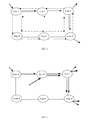
- Fig. 1 is a schematic view showing an existing p2mp ring network protection method.
- a solid line without any arrow represents a physical link
- a solid line with an arrow represents LSP for a p2mp service
- a dotted line with an arrow represents an established protection channel.
- the p2mp service enters the ring at a node A, while it leaves the ring at nodes D and E. Accordingly, it is required to establish two protection channels for the p2mp service.
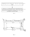
- Fig.2 is a schematic view showing a situation where there are two p2mp services in one ring.
- another p2mp service enters the ring at a node F, while it leaves the ring at nodes D and E.
- this p2mp service and the p2mp service shown in Fig.1 have same off-ring nodes, they have different on-ring nodes and thus another two protection channels are required to be established for this p2mp service.
- the protection channels are established by taking each p2mp service which enters the ring as a unit.
- the number of the protection channels established for each ring depends linearly on the number of the p2mp services.
- there are too many protection channels and the resultant network structure is very complex.
- the present disclosure provides a p2mp ring network protection method and device, which can simplify the network structure and save the network resources.
- a p2mp ring network protection method includes performing following processing in each ring in the p2mp loop network:
- a p2mp ring network protection device includes:
- Each protection group in the ring corresponds to a pair of closed loop channels in opposite directions.
- one of the closed loop channels is taken as a working channel, and the other one of the closed loop channels is taken as a protection channel.
- the p2mp services with an identical off-ring node form one protection group.
- the node includes a first processing module and a second processing module.
- the first processing module is configured to, when receiving a data stream of any p2mp service, determine a type of the node corresponding to the p2mp service, and transmit the received data stream and the determined type of the node to the second processing module, the type of the node including an on-ring node, an intermediate node, and an off-ring node.
- the second processing module is configured to perform different processing on the received data stream according to the type of the node.
- the protection channel is not established by taking one p2mp service as a unit. Instead, the p2mp services with an identical off-ring node are taken as one protection group, and a pair of closed loop channels in opposite directions is established for each protection group.
- the network structure can be simplified, and the network resources as well as the implementation cost can be reduced.
- the present disclosure provides a p2mp ring network protection method, which can simplify network structure and save network resources.
- Fig.3 is a flow chart of a p2mp ring network protection method according to one embodiment of the present disclosure. Each ring in the ring network may be processed in a way shown in Fig.3 . As shown in Fig. 3 , the method includes following steps.
- Step 31 determining p2mp services having same off-ring node as a protection group.
- the p2mp services having the same off-ring node may be determined as a protection group. As shown in Fig.2 , one p2mp service enters a ring from a node A and leaves the ring at nodes D and E; another p2mp service enters the ring at a node F and leaves the ring at the nodes D and E; then, the two p2mp services belong to the same protection group.
- Step 32 establishing a pair of closed loop channels in opposite directions for each protection group; for each p2mp service, taking one of the closed loop channels as a working channel, and taking the other of the closed loop channels as a protection channel.
- a pair of closed loop channels in opposite directions i.e., a closed loop channel in a clockwise direction and a closed loop channel in a counterclockwise direction, may be established for each protection group, and the two channels are protection channels relative to each other.
- one of the closed loop channels is taken as the working channel, while the other of the closed loop channels is taken as the protection channel.
- n 2 when there are two off-ring nodes, there are C n 2 combinations for these off-ring nodes, e.g., a combination of nodes A and B when they are off-ring nodes, or a combination of nodes A and C when they are off-ring nodes.
- C n 3 when there are three off-ring nodes, there are C n 3 combinations for these off-ring nodes, and when there are m (m ⁇ n) off-ring nodes, there are C n m combinations for these off-ring nodes.
- the possible combinations for the off-ring nodes are very limited in one ring, i.e., the number of the protection groups is very limited.
- the number of the closed loop channels desired to be established is very limited too.
- the time when the closed loop channel is established may be determined according to the practical need. For example, after one p2mp service enters the ring from a certain node, a pair of closed loop channels in opposite directions are established for this p2mp service. Then, when another p2mp service enters the ring from another node and it is found that this p2mp service and the previous p2mp service have same off-ring node, the pair of previously established closed loop channels in opposite directions may be multiplexed by this p2mp service. When it is found that this p2mp service and the previous p2mp service have different off-ring nodes, a new pair of closed loop channels in opposite directions are required to be established for this p2mp service.
- Fig.4 is a schematic view showing a pair of closed loop channels in opposite directions shared by two p2mp services according to one embodiment of the present disclosure.
- a solid line without any arrow represents a physical link
- a solid line with an arrow represents an LSP for a p2mp service
- a dotted line with an arrow represents an established closed loop channel.
- One p2mp service enters the ring from a node A and leaves the ring from nodes D and E.
- the closed loop channel in a clockwise direction is taken as its working channel
- the closed loop channel in a counterclockwise direction is taken as its protection channel.
- Another p2mp service enters the ring from a node C and leaves the ring from the nodes D and E.
- the closed loop channel in the counterclockwise direction is taken as its working channel
- the closed loop channel in the clockwise direction is taken as its protection channel.
- Steps 31 and 32 in Fig.3 are provided merely for ease of the description, but shall not be used to limit an order thereof.
- the p2mp service may be processed by allocating a label for a downstream node by an upstream node, and the allocated label may be used for identifying a next hop node of a data stream.
- a type of the node itself corresponding to this p2mp service may first be determined, and the type includes an on-ring node, an intermediate node, and an off-ring node. Then, different processing manners such as following processing manners 1) to 3) may be performed on the received data stream according to different types of the node.
- a working channel label is allocated for a node adjacent to the current node in a direction of the working channel after the LSP layer label switching has been performed on the received data stream.
- the allocated working channel label is packaged into the received data stream, and then transmitted to the node adjacent to the current node in the direction of the working channel.
- the completion of the LSP layer label switching may refer to the related art.
- a working channel label is allocated for a node adjacent to the current node in the direction of the working channel.
- An original working channel label in the received data stream is replaced with the allocated working channel label, and the resultant data stream is then transmitted to the node adjacent to the current node in the direction of the working channel.
- determining that the type of the current node itself is an off-ring node further determining whether or not a node adjacent to the current node in the direction of the working channel is also an off-ring node. If not, the working channel label in the received data stream is removed, and an operation of leaving the ring is performed. If yes, the working channel label in the received data stream is removed, an operation of leaving the ring is performed, the working channel label is allocated for the node adjacent to the current node in the direction of the working channel, the original working channel label in the received data stream is replaced with the allocated working channel label, and then the resultant data stream is transmitted to the node adjacent to the current node in the direction of the working channel.
- Fig. 5 is a schematic view showing a p2mp service processing mode according to one embodiment of the present disclosure. As shown in Fig.5 , a solid line without any arrow represents a physical link, and a solid line with an arrow represents an LSP for the p2mp service.
- the LSP layer label switching is performed at first on data stream of the p2mp service at the node A; after the switching, a label 1000 is obtained is allocated by the node D. Then, a working channel label 410 is allocated for a node F, packaged into the data stream, and transmitted to node F. A working channel label 510 is allocated by the node F for the node E, the original working channel label 410 in the received data stream is replaced with the working channel label 510, and the resultant data stream is then transmitted to the node E.
- the working channel label 510 in the received data stream is removed at the node E, and the node E performs an operation of leaving the ring.
- the node E allocates a working channel label 610 for the node D, replaces the working channel label 510 in the received data stream with the working channel label 610, and transmits the resultant data stream to the node D.
- the working channel label 610 in the received data stream is removed at the node D, and the node D performs an operation of leaving the ring.
- the execution of the operation of leaving the ring and the processing subsequent to this operation may refer to the related art.
- the LSP layer label switching is performed at first on the data stream of the p2mp service at the node F; after the switching, a label 2000 is obtained and allocated by the node D. Then, the working channel label 510 is allocated for the node E, packaged into the data stream, and transmitted to the node E. The working channel label 510 in the received data stream is removed at the node E, and an operation of leaving the ring is performed at the node E.
- the node E allocates the working channel label 610 for the node D, and replaces the working channel label 510 in the received data stream with the working channel label 610, and then transmits the resultant data stream to the node D.
- the working channel label 610 in the received data stream is removed at the node D, and an operation of leaving the loop is performed.
- each node has no need to process the inner labels, i.e., LSP labels 1000 and 2000, and merely needs to process outer labels, i.e., channel labels.
- each upstream node independently allocates a working channel label for a downstream node, and the working channel label is usually at a length of 20 bits.
- the label allocated by each upstream node in the embodiments of the present disclosure may be derived from a single label space, which is called as an environment label.
- the data stream of the p2mp service when the data stream of the p2mp service cannot be transmitted to a part of, or all of, the off-ring nodes in the direction of the working channel due to a link fault, the data stream may be transmitted in a direction of the protection channel to the off-ring node to which the data stream of the p2mp service cannot be transmitted in the direction of the working channel.
- any node which has received the data stream of the p2mp service determines that there is a fault in a link between the node and a node adjacent thereto in the direction of the working channel, the following processing may be performed.
- a protection channel label is allocated for a node adjacent to the current node in the direction of the protection channel after the LSP layer label switching has been performed on the received data stream.
- the allocated protection channel label is packaged into the received data stream, and then transmitted to the node adjacent thereto in the direction of the protection channel.
- a protection channel label is allocated for a node adjacent to the current node in the direction of the protection channel, an original working channel label in the received data stream is replaced with the allocated protection channel label, and the resultant data stream is then transmitted to the node adjacent thereto in the direction of the protection channel.
- a protection channel label is allocated for a node adjacent to the current node in the direction of the protection channel, an original protection channel label in the received data stream is replaced with the allocated protection channel label, and the resultant data stream is then transmitted to the node adjacent thereto in the direction of the protection channel.
- the protection channel label in the received data stream is removed, and an operation of leaving the ring is performed.
- a protection channel label is allocated for the node adjacent thereto in the direction of the protection channel, the original protection channel label in the received data stream is replaced with the allocated protection channel label, and the resultant data stream is then transmitted to the node adjacent thereto in the direction of the protection channel.
- the protection channel label in the received data stream is removed, and an operation of leaving the ring is performed.
- the protection channel label in the received data stream is removed, and an operation of leaving the ring is performed.
- Fig.6 is a schematic view showing a fault processing mode according to one embodiment of the present disclosure.
- one p2mp service enters the ring at a node A and leaves the ring at nodes C and D. Presumed that there is a link fault between the nodes C and D, a data stream transmitted to node C will not be affected.
- a working channel label is packaged at the node A, replaced at a node B, and removed at the node C, and then an operation of leaving the ring is performed.
- a working path from the node A to the node C is: the node A-the node B-the node C
- a label processing flow includes packaging the working channel label Rcw_A(B) at the node A-replacing Rcw_A(B) with Rcw_A(C) at the node B-removing Rcw_A(c) at the node C.
- the data stream transmitted to the node D will be affected.
- it is required to perform protection switching at the node C, so as to switch to the protection channel in an opposite direction.
- the working channel label in the received data stream is replaced with the protection channel label allocated for the node B, and the resultant data stream is then transmitted to the node B.
- the original protection channel label in the received data stream is sequentially replaced with the protection channel label allocated for the adjacent node in the direction of the protection channel.
- the protection channel label in the received data stream is removed, and an operation of leaving the ring is performed.
- a working path from the node A to the node D is: the node A-the node B-the node C-the node B-the node A-the node F-the node E-the node D
- a label processing flow includes: packing the working channel label Rcw_A(B) at the node A-replacing Rcw_A(B) with Rcw_A(C) at the node B-replacing Rcw_A(C) with Rap_A(B) at the node C-replacing Rap_A(B) with Rap_A(A) at the node B-replacing Rap_A(A) with Rap_A(F) at the node A-replacing R_A(F) with Rap_A(E) at the node F-replacing Rap_A(E) with Rap_A(D) at the node E-removing Rap_A(D) at the node D.
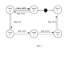
- one p2mp service enters the ring at a node A and leaves the ring at nodes C and D. Presumed that there is a link fault between nodes B and C, the data stream transmitted to the node C will be affected. With respect to the data stream of the p2mp service, a working channel label is packaged at the node A, and the protection switching is performed at the node B so as to switch to the protection channel in an opposite direction. At the nodes B, A, F, E and D, the protection channel labels are sequentially replaced. At the node C, the protection channel label is removed, and an operation of leaving the ring is performed.
- a working path from the node A to the node C is: the node A-the node B-the node A-the node F-the node E-the node D-the node C
- a label processing flow includes: packing the working channel label Rcw_A(B) at the node A-replacing Rcw_A(B) with the protection channel label Rap_A(A) at the node B-replacing Rap_A(A) with Rap_A(F) at the node A-replacing Rap_A(F) with Rap_A(E) at the node F-replacing Rap_A(E) with Rap_A(D) at the node E-replacing Rap_A(D) with Rap_A(C) at the node D-removing Rap_A(C) at the node C.
- the data stream transmitted to the node D will also be affected.
- a working channel label is packaged at the node A, and the protection switching is performed at the node B so as to switch to the protection channel in an opposite direction.
- the protection channel labels are replaced sequentially.
- the protection channel label is removed, and an operation of leaving the ring is performed.
- a working path from the node A to the node D is: the node A-the node B-the node A-the node F-the node E-the node D
- a label processing flow includes: packaging the working channel label Rcw_A(B) at the node A-replacing Rcw_A(B) with the protection channel label Rap_A(A) at the node B-replacing Rap_A(A) with Rap_A(F) at the node A-replacing Rap_A(F) with Rap_A(E) at the node F-replacing Rap_A(E) with Rap_A(D) at the node E-removing Rap_A(D) at the node D.
- a situation where there is a fault at one node is equivalent to a situation where there is a fault at two links connected with the node.
- the processing mode therefor is the same as those mentioned above when there is a link fault, and thus will not be repeated herein.
- the present disclosure further provides in one embodiment a p2mp ring network protection device and a node, which will be described hereinafter.
- the p2mp ring network protection device may include a protection module configured to, perform following processing with respect to each ring in the p2mp ring network.
- the processing includes: determine p2mp services with an identical off-ring node as a protection group; establishing a pair of closed loop channels in opposite directions for each protection group; for each p2mp service, taking one of the closed loop channels as a working channel, and taking the other one of the closed loop channels as a protection channel.
- the node is located at one ring of the ring network.
- Each protection group in the ring corresponds to a pair of closed loop channels in opposite directions.
- one of the closed loop channels is taken as its working channel, and the other one of the closed loop channels is taken as its protection channel.
- the p2mp services with an identical off-ring node form one protection group.
- the node may include a first processing module and a second processing module.
- the first processing module is configured to, when receiving a data stream of any p2mp service, determine a type of the node where the p2mp service is located, and transmit the received data stream and the determined type of the node to the second processing module.
- the type of the node includes an on-ring node, an intermediate node, and an off-ring node.
- the second processing module is configured to perform different processing on the received data stream according to different types of the node.
- the second processing module when determining that a current node is an on-ring node, is configured to allocate a working channel label for a node adjacent to the current node in a direction of the working channel after the LSP layer label switching has been performed on the received data stream, package the allocated working channel label into the received data stream, and then transmit the resultant data stream to the node adjacent to the current node in the direction of the working channel.
- the second processing module is configured to allocate a working channel label for a node adjacent to the current node in the direction of the working channel, replace an original working channel label in the received data stream with the allocated working channel label, and then transmit the resultant data stream to the node adjacent to the current node in the direction of the working channel.
- the second processing module is configured to further determine whether or not a node adjacent to the current node in the direction of the working channel is also an off-ring node; if not, remove the working channel label in the received data stream, and perform an operation of leaving the ring; and if yes, remove the working channel label in the received data stream, perform an operation of leaving the ring, allocate the working channel label for the node adjacent to the current node in the direction of the working channel, replace the original working channel label in the received data stream with the allocated working channel label, and then transmit the resultant data stream to the node adjacent to the current node in the direction of the working channel.
- the second processing module may further be configured to:
- the second processing module may further be configured to:
Landscapes
- Engineering & Computer Science (AREA)
- Computer Networks & Wireless Communication (AREA)
- Signal Processing (AREA)
- Small-Scale Networks (AREA)
- Data Exchanges In Wide-Area Networks (AREA)
Abstract
Description
- The present application claims a priority of the Chinese patent application No.
201310045807.2 filed on February 5, 2013 - The present disclosure relates to the field of network technology, in particular to a point-to-multipoint ring network protection method and device.
- In an existing point-to-multipoint (p2mp) ring network protection method, usually a closed-loop channel in a direction opposite to each working channel is established as a protection channel for each working channel. The allocation of labels for the protection channel must be associated with the allocation of labels for the working channel, so as to ensure LSP (label switching path)-based protection switching for a p2mp service between the working channel and the protection channel.
-
Fig. 1 is a schematic view showing an existing p2mp ring network protection method. As shown inFig.1 , a solid line without any arrow represents a physical link, a solid line with an arrow represents LSP for a p2mp service, and a dotted line with an arrow represents an established protection channel. As can be seen fromFig.1 , the p2mp service enters the ring at a node A, while it leaves the ring at nodes D and E. Accordingly, it is required to establish two protection channels for the p2mp service. -
Fig.2 is a schematic view showing a situation where there are two p2mp services in one ring. As shown inFig.2 , in addition to the p2mp service shown inFig.1 , another p2mp service enters the ring at a node F, while it leaves the ring at nodes D and E. Although this p2mp service and the p2mp service shown inFig.1 have same off-ring nodes, they have different on-ring nodes and thus another two protection channels are required to be established for this p2mp service. - It can therefore be seen that, in the related art, the protection channels are established by taking each p2mp service which enters the ring as a unit. In other words, the number of the protection channels established for each ring depends linearly on the number of the p2mp services. As a result, there are too many protection channels, and the resultant network structure is very complex.
- In view of this, the present disclosure provides a p2mp ring network protection method and device, which can simplify the network structure and save the network resources.
- In order to achieve the above object, technical solutions of the present disclosure are as follows.
- A p2mp ring network protection method, includes performing following processing in each ring in the p2mp loop network:
- determining p2mp services with an identical off-ring node as a protection group; and
- establishing a pair of closed loop channels in opposite directions for each protection group; for each p2mp service, taking one of the closed loop channels as a working channel, and taking the other one of the closed loop channels as a protection channel.
- A p2mp ring network protection device includes:
- a protection module configured to, with respect to each ring in the p2mp ring network, determine p2mp services with an identical off-ring node as a protection group; establish a pair of closed loop channels in opposite directions for each protection group; for each p2mp service, take one of the closed loop channels as a working channel, and take the other one of the closed loop channels as a protection channel.
- A node located at one ring of a ring network. Each protection group in the ring corresponds to a pair of closed loop channels in opposite directions. For each p2mp service, one of the closed loop channels is taken as a working channel, and the other one of the closed loop channels is taken as a protection channel. The p2mp services with an identical off-ring node form one protection group.
- The node includes a first processing module and a second processing module. The first processing module is configured to, when receiving a data stream of any p2mp service, determine a type of the node corresponding to the p2mp service, and transmit the received data stream and the determined type of the node to the second processing module, the type of the node including an on-ring node, an intermediate node, and an off-ring node.
- The second processing module is configured to perform different processing on the received data stream according to the type of the node.
- According to the embodiments of the present disclosure, the protection channel is not established by taking one p2mp service as a unit. Instead, the p2mp services with an identical off-ring node are taken as one protection group, and a pair of closed loop channels in opposite directions is established for each protection group. As a result, the network structure can be simplified, and the network resources as well as the implementation cost can be reduced.
-
-
Fig.1 is a schematic view showing an existing p2mp ring network protection method; -
Fig.2 is a schematic view showing a situation where there are two p2mp services in one ring; -
Fig.3 is a flow chart of a p2mp ring network protection method according to one embodiment of the present disclosure; -
Fig.4 is a schematic view showing a pair of closed loop channels in opposite directions shared by two p2mp services according to one embodiment of the present disclosure; -
Fig.5 is a schematic view showing a p2mp service processing mode according to one embodiment of the present disclosure; -
Fig.6 is a schematic view showing a fault processing mode according to one embodiment of the present disclosure; and -
Fig.7 is a schematic view showing a fault processing mode according to another embodiment of the present disclosure. - In order to overcome the existing drawbacks in the related art, the present disclosure provides a p2mp ring network protection method, which can simplify network structure and save network resources.
- In order to make the technical solutions of the present disclosure more apparent, the technical solutions of the present disclosure will be described hereinafter in conjunction with the drawings and the embodiments.
-
Fig.3 is a flow chart of a p2mp ring network protection method according to one embodiment of the present disclosure. Each ring in the ring network may be processed in a way shown inFig.3 . As shown inFig. 3 , the method includes following steps. - Step 31: determining p2mp services having same off-ring node as a protection group.
- In the technical solution of the present disclosure, the p2mp services having the same off-ring node may be determined as a protection group. As shown in
Fig.2 , one p2mp service enters a ring from a node A and leaves the ring at nodes D and E; another p2mp service enters the ring at a node F and leaves the ring at the nodes D and E; then, the two p2mp services belong to the same protection group. - Step 32: establishing a pair of closed loop channels in opposite directions for each protection group; for each p2mp service, taking one of the closed loop channels as a working channel, and taking the other of the closed loop channels as a protection channel.
- A pair of closed loop channels in opposite directions, i.e., a closed loop channel in a clockwise direction and a closed loop channel in a counterclockwise direction, may be established for each protection group, and the two channels are protection channels relative to each other. For each p2mp service, one of the closed loop channels is taken as the working channel, while the other of the closed loop channels is taken as the protection channel.
- Theoretically, for a ring including n nodes, when there are two off-ring nodes, there are


- The time when the closed loop channel is established may be determined according to the practical need. For example, after one p2mp service enters the ring from a certain node, a pair of closed loop channels in opposite directions are established for this p2mp service. Then, when another p2mp service enters the ring from another node and it is found that this p2mp service and the previous p2mp service have same off-ring node, the pair of previously established closed loop channels in opposite directions may be multiplexed by this p2mp service. When it is found that this p2mp service and the previous p2mp service have different off-ring nodes, a new pair of closed loop channels in opposite directions are required to be established for this p2mp service.
-
Fig.4 is a schematic view showing a pair of closed loop channels in opposite directions shared by two p2mp services according to one embodiment of the present disclosure. As shown inFig.4 , a solid line without any arrow represents a physical link, a solid line with an arrow represents an LSP for a p2mp service, and a dotted line with an arrow represents an established closed loop channel. One p2mp service enters the ring from a node A and leaves the ring from nodes D and E. For this p2mp service, the closed loop channel in a clockwise direction is taken as its working channel, and the closed loop channel in a counterclockwise direction is taken as its protection channel. Another p2mp service enters the ring from a node C and leaves the ring from the nodes D and E. For this p2mp service, the closed loop channel in the counterclockwise direction is taken as its working channel, and the closed loop channel in the clockwise direction is taken as its protection channel. - It should be appreciated that, Steps 31 and 32 in
Fig.3 are provided merely for ease of the description, but shall not be used to limit an order thereof. - In the technical solution of the present disclosure, the p2mp service may be processed by allocating a label for a downstream node by an upstream node, and the allocated label may be used for identifying a next hop node of a data stream.
- For each node in the ring, when receiving data stream of any p2mp service, a type of the node itself corresponding to this p2mp service may first be determined, and the type includes an on-ring node, an intermediate node, and an off-ring node. Then, different processing manners such as following processing manners 1) to 3) may be performed on the received data stream according to different types of the node.
- 1) When determining that the type of the current node itself is an on-ring node, a working channel label is allocated for a node adjacent to the current node in a direction of the working channel after the LSP layer label switching has been performed on the received data stream. The allocated working channel label is packaged into the received data stream, and then transmitted to the node adjacent to the current node in the direction of the working channel.
- The completion of the LSP layer label switching may refer to the related art.
- 2) When determining that the type of the current node itself is an intermediate node, a working channel label is allocated for a node adjacent to the current node in the direction of the working channel. An original working channel label in the received data stream is replaced with the allocated working channel label, and the resultant data stream is then transmitted to the node adjacent to the current node in the direction of the working channel.
- 3) When determining that the type of the current node itself is an off-ring node, further determining whether or not a node adjacent to the current node in the direction of the working channel is also an off-ring node. If not, the working channel label in the received data stream is removed, and an operation of leaving the ring is performed. If yes, the working channel label in the received data stream is removed, an operation of leaving the ring is performed, the working channel label is allocated for the node adjacent to the current node in the direction of the working channel, the original working channel label in the received data stream is replaced with the allocated working channel label, and then the resultant data stream is transmitted to the node adjacent to the current node in the direction of the working channel.
-
Fig. 5 is a schematic view showing a p2mp service processing mode according to one embodiment of the present disclosure. As shown inFig.5 , a solid line without any arrow represents a physical link, and a solid line with an arrow represents an LSP for the p2mp service. - For the p2mp service which enters a ring from a node A and leaves the ring at nodes E and D, the LSP layer label switching is performed at first on data stream of the p2mp service at the node A; after the switching, a
label 1000 is obtained is allocated by the node D. Then, a working channel label 410 is allocated for a node F, packaged into the data stream, and transmitted to node F. A working channel label 510 is allocated by the node F for the node E, the original working channel label 410 in the received data stream is replaced with the working channel label 510, and the resultant data stream is then transmitted to the node E. The working channel label 510 in the received data stream is removed at the node E, and the node E performs an operation of leaving the ring. The node E allocates a working channel label 610 for the node D, replaces the working channel label 510 in the received data stream with the working channel label 610, and transmits the resultant data stream to the node D. The working channel label 610 in the received data stream is removed at the node D, and the node D performs an operation of leaving the ring. The execution of the operation of leaving the ring and the processing subsequent to this operation may refer to the related art. - For the p2mp service which enters the ring at the node F and leaves the ring at the nodes E and D, the LSP layer label switching is performed at first on the data stream of the p2mp service at the node F; after the switching, a
label 2000 is obtained and allocated by the node D. Then, the working channel label 510 is allocated for the node E, packaged into the data stream, and transmitted to the node E. The working channel label 510 in the received data stream is removed at the node E, and an operation of leaving the ring is performed at the node E. The node E allocates the working channel label 610 for the node D, and replaces the working channel label 510 in the received data stream with the working channel label 610, and then transmits the resultant data stream to the node D. The working channel label 610 in the received data stream is removed at the node D, and an operation of leaving the loop is performed. - It can therefore be seen that, in the process as shown in
Fig.5 , the label nesting is performed when the data stream is transmitted in the ring. Each node has no need to process the inner labels, i.e.,LSP labels - In addition, each upstream node independently allocates a working channel label for a downstream node, and the working channel label is usually at a length of 20 bits. In order to prevent collision with labels allocated for downstream nodes in an existing point-to-point (p2p) mode, the label allocated by each upstream node in the embodiments of the present disclosure may be derived from a single label space, which is called as an environment label.
- Moreover, for any p2mp service, when the data stream of the p2mp service cannot be transmitted to a part of, or all of, the off-ring nodes in the direction of the working channel due to a link fault, the data stream may be transmitted in a direction of the protection channel to the off-ring node to which the data stream of the p2mp service cannot be transmitted in the direction of the working channel.
- To be specific, when any node which has received the data stream of the p2mp service determines that there is a fault in a link between the node and a node adjacent thereto in the direction of the working channel, the following processing may be performed.
- 1) When determining that a current node is an on-ring node, a protection channel label is allocated for a node adjacent to the current node in the direction of the protection channel after the LSP layer label switching has been performed on the received data stream. The allocated protection channel label is packaged into the received data stream, and then transmitted to the node adjacent thereto in the direction of the protection channel.
- 2) When determining that the current node is an intermediate node or an off-ring node, a protection channel label is allocated for a node adjacent to the current node in the direction of the protection channel, an original working channel label in the received data stream is replaced with the allocated protection channel label, and the resultant data stream is then transmitted to the node adjacent thereto in the direction of the protection channel.
- The following processing which are performed at each node which receives the data stream carrying the protection channel label.
- 1) When determining that a current node is an intermediate node, a protection channel label is allocated for a node adjacent to the current node in the direction of the protection channel, an original protection channel label in the received data stream is replaced with the allocated protection channel label, and the resultant data stream is then transmitted to the node adjacent thereto in the direction of the protection channel.
- 2) When determining that the current node is an off-ring node and a node adjacent to the current node in the direction of the protection channel is also an off-ring node as well as there is a normal link between the current node and the adjacent node in the direction of the protection channel, the protection channel label in the received data stream is removed, and an operation of leaving the ring is performed. In addition, a protection channel label is allocated for the node adjacent thereto in the direction of the protection channel, the original protection channel label in the received data stream is replaced with the allocated protection channel label, and the resultant data stream is then transmitted to the node adjacent thereto in the direction of the protection channel.
- 3) When determining that the current node is an off-ring node and a node adjacent to the current node in the direction of the protection channel is also an off-ring node as well as there is a link fault between the current node and the adjacent node in the direction of the protection channel, the protection channel label in the received data stream is removed, and an operation of leaving the ring is performed.
- 4) When determining that the current node is an off-ring node and a node adjacent to the current node in the direction of the protection channel is not an off-ring node, the protection channel label in the received data stream is removed, and an operation of leaving the ring is performed.
-
Fig.6 is a schematic view showing a fault processing mode according to one embodiment of the present disclosure. As shown inFig.6 , one p2mp service enters the ring at a node A and leaves the ring at nodes C and D. Presumed that there is a link fault between the nodes C and D, a data stream transmitted to node C will not be affected. With respect to the data stream of the p2mp service, a working channel label is packaged at the node A, replaced at a node B, and removed at the node C, and then an operation of leaving the ring is performed. In other words, a working path from the node A to the node C is: the node A-the node B-the node C, and a label processing flow includes packaging the working channel label Rcw_A(B) at the node A-replacing Rcw_A(B) with Rcw_A(C) at the node B-removing Rcw_A(c) at the node C. - However, the data stream transmitted to the node D will be affected. Correspondingly, it is required to perform protection switching at the node C, so as to switch to the protection channel in an opposite direction. At the node C, the working channel label in the received data stream is replaced with the protection channel label allocated for the node B, and the resultant data stream is then transmitted to the node B. At the nodes B, A, F and E, the original protection channel label in the received data stream is sequentially replaced with the protection channel label allocated for the adjacent node in the direction of the protection channel. At the node D, the protection channel label in the received data stream is removed, and an operation of leaving the ring is performed. In other words, a working path from the node A to the node D is: the node A-the node B-the node C-the node B-the node A-the node F-the node E-the node D, and a label processing flow includes: packing the working channel label Rcw_A(B) at the node A-replacing Rcw_A(B) with Rcw_A(C) at the node B-replacing Rcw_A(C) with Rap_A(B) at the node C-replacing Rap_A(B) with Rap_A(A) at the node B-replacing Rap_A(A) with Rap_A(F) at the node A-replacing R_A(F) with Rap_A(E) at the node F-replacing Rap_A(E) with Rap_A(D) at the node E-removing Rap_A(D) at the node D.
- As shown in
Fig.7 , which is schematic view showing a fault processing mode according to another embodiment of the present disclosure, one p2mp service enters the ring at a node A and leaves the ring at nodes C and D. Presumed that there is a link fault between nodes B and C, the data stream transmitted to the node C will be affected. With respect to the data stream of the p2mp service, a working channel label is packaged at the node A, and the protection switching is performed at the node B so as to switch to the protection channel in an opposite direction. At the nodes B, A, F, E and D, the protection channel labels are sequentially replaced. At the node C, the protection channel label is removed, and an operation of leaving the ring is performed. In other words, a working path from the node A to the node C is: the node A-the node B-the node A-the node F-the node E-the node D-the node C, and a label processing flow includes: packing the working channel label Rcw_A(B) at the node A-replacing Rcw_A(B) with the protection channel label Rap_A(A) at the node B-replacing Rap_A(A) with Rap_A(F) at the node A-replacing Rap_A(F) with Rap_A(E) at the node F-replacing Rap_A(E) with Rap_A(D) at the node E-replacing Rap_A(D) with Rap_A(C) at the node D-removing Rap_A(C) at the node C. - The data stream transmitted to the node D will also be affected. With respect to the data stream of the p2mp service, a working channel label is packaged at the node A, and the protection switching is performed at the node B so as to switch to the protection channel in an opposite direction. At the nodes B, A, F and E, the protection channel labels are replaced sequentially. At the node D, the protection channel label is removed, and an operation of leaving the ring is performed. In other words, a working path from the node A to the node D is: the node A-the node B-the node A-the node F-the node E-the node D, and a label processing flow includes: packaging the working channel label Rcw_A(B) at the node A-replacing Rcw_A(B) with the protection channel label Rap_A(A) at the node B-replacing Rap_A(A) with Rap_A(F) at the node A-replacing Rap_A(F) with Rap_A(E) at the node F-replacing Rap_A(E) with Rap_A(D) at the node E-removing Rap_A(D) at the node D.
- A situation where there is a fault at one node is equivalent to a situation where there is a fault at two links connected with the node. The processing mode therefor is the same as those mentioned above when there is a link fault, and thus will not be repeated herein.
- To this, the introduction of the method of the embodiments of the present disclosure is finished.
- Based on the above, the present disclosure further provides in one embodiment a p2mp ring network protection device and a node, which will be described hereinafter.
- The p2mp ring network protection device may include a protection module configured to, perform following processing with respect to each ring in the p2mp ring network. The processing includes: determine p2mp services with an identical off-ring node as a protection group; establishing a pair of closed loop channels in opposite directions for each protection group; for each p2mp service, taking one of the closed loop channels as a working channel, and taking the other one of the closed loop channels as a protection channel.
- The node is located at one ring of the ring network. Each protection group in the ring corresponds to a pair of closed loop channels in opposite directions. For each p2mp service, one of the closed loop channels is taken as its working channel, and the other one of the closed loop channels is taken as its protection channel. The p2mp services with an identical off-ring node form one protection group.
- The node may include a first processing module and a second processing module. The first processing module is configured to, when receiving a data stream of any p2mp service, determine a type of the node where the p2mp service is located, and transmit the received data stream and the determined type of the node to the second processing module. The type of the node includes an on-ring node, an intermediate node, and an off-ring node. The second processing module is configured to perform different processing on the received data stream according to different types of the node.
- To be specific, when determining that a current node is an on-ring node, the second processing module is configured to allocate a working channel label for a node adjacent to the current node in a direction of the working channel after the LSP layer label switching has been performed on the received data stream, package the allocated working channel label into the received data stream, and then transmit the resultant data stream to the node adjacent to the current node in the direction of the working channel.
- When determining that the current node is an intermediate node, the second processing module is configured to allocate a working channel label for a node adjacent to the current node in the direction of the working channel, replace an original working channel label in the received data stream with the allocated working channel label, and then transmit the resultant data stream to the node adjacent to the current node in the direction of the working channel.
- When determining that the node is an off-ring node, the second processing module is configured to further determine whether or not a node adjacent to the current node in the direction of the working channel is also an off-ring node; if not, remove the working channel label in the received data stream, and perform an operation of leaving the ring; and if yes, remove the working channel label in the received data stream, perform an operation of leaving the ring, allocate the working channel label for the node adjacent to the current node in the direction of the working channel, replace the original working channel label in the received data stream with the allocated working channel label, and then transmit the resultant data stream to the node adjacent to the current node in the direction of the working channel.
- In addition, when determining that the data stream of the p2mp service cannot be received at a part of, or all of, the off-ring nodes due to a link fault between the current node and the adjacent node in the direction of the working channel, the second processing module may further be configured to:
- when determining that the current node is an on-ring node, allocate a protection channel label for the node adjacent to the current node in the direction of the protection channel after the LSP layer label switching has been performed on the received data stream, package the allocated protection channel label into the received data stream, and then transmit the resultant data stream to the node adjacent thereto in the direction of the protection channel; and
- when determining that the current node is an intermediate node or an off-ring node, allocate a protection channel label for the node adjacent to the current node in the direction of the protection channel, replace an original working channel label in the received data stream with the allocated protection channel label, and then transmit the resultant data stream to the node adjacent thereto in the direction of the protection channel.
- When receiving the data stream carrying the protection channel label, the second processing module may further be configured to:
- when determining that the current node is an intermediate node, allocate the protection channel label for a node adjacent to the current node in the direction of the protection channel, replace an original protection channel label in the received data stream with the allocated protection channel label, and then transmit the resultant data stream to the node adjacent thereto in the direction of the protection channel;
- when determining that the current node is an off-ring node, a node adjacent to the current node in the direction of the protection channel is also an off-ring node and there is a normal link between the current node and the adjacent node in the direction of the protection channel, remove the protection channel label in the received data stream, perform an operation of leaving the ring, allocate a protection channel label for the node adjacent thereto in the direction of the protection channel, replace the original protection channel label in the received data stream with the allocated protection channel label, and then transmit the resultant data stream to the node adjacent thereto in the direction of the protection channel;
- when determining that the current node is an off-ring node, a node adjacent to the current node in the direction of the protection channel is also an off-ring node and there is a link fault between the current node and the adjacent node in the direction of the protection channel, remove the protection channel label in the received data stream, and perform an operation of leaving the ring; and
- when determining that the current node is an off-ring node and a node adjacent to the current node in the direction of the protection channel is not an off-ring node, remove the protection channel label in the received data stream, and perform an operation of leaving the ring.
- The specific working process of the above-mentioned device may refer to the above method, and thus will not be repeated herein.
- The above are merely preferred embodiments of the present disclosure, but shall not be used to limit the present disclosure. A person skilled in eth art may make modifications, substitutions and improvements without departing from the spirit and principle of the present disclosure, and these modifications, substitutions and improvements shall also fall within the scope of the present disclosure.
Claims (9)
- A point-to-multipoint (p2mp) ring network protection method, comprising:performing following processing in each ring in the p2mp ring network:determining p2mp services with an identical off-ring node as a protection group; andestablishing a pair of closed loop channels in opposite directions for each protection group; for each p2mp service, taking one of the closed loop channels as a working channel, and taking the other one of the closed loop channels as a protection channel.
- The method according to claim 1, further comprising:for each node in the ring, when receiving a data stream of any p2mp service, determining a type of each node corresponding to the p2mp service, and performing different processing on the received data stream according to different types of the nodes, the type comprising an on-ring node, an intermediate node, and an off-ring node.
- The method according to claim 2, wherein the step of performing different processing on the received data stream according to different types of the nodes comprises:when determining that the type of one node is the on-ring node, allocating a working channel label for a node adjacent to the one node in a direction of the working channel after label switching path (LSP) layer label switching has been performed on the received data stream, packaging the allocated working channel label into the received data stream, and then transmitting the resultant data stream to the node adjacent to the one node in the direction of the working channel;when determining that the type of one node is an intermediate node, allocating a working channel label for a node adjacent to the one node in the direction of the working channel, replacing an original working channel label in the received data stream with the allocated working channel label, and then transmitting the resultant data stream to the node adjacent to the one node in the direction of the working channel; andwhen determining that the type of one node is the off-ring node, determining whether or not the type of a node adjacent to the one node in the direction of the working channel is also the off-ring node; if not, removing the working channel label in the received data stream and performing an operation of leaving the ring; if yes, removing the working channel label in the received data stream, performing an operation of leaving the ring, allocating a working channel label for the node adjacent to the one node in the direction of the working channel, replacing the original working channel label in the received data stream with the allocated working channel label, and then transmitting the resultant data stream to the node adjacent to the one node in the direction of the working channel.
- The method according to claim 3, further comprising a step of:when the data stream of the p2mp service is unable to be transmitted to a part of, or all of, the off-ring nodes in the direction of the working channel due to a link fault, transmitting the data stream in a direction of the protection channel to each off-ring node to which the data stream of the p2mp service is unable to be transmitted in the direction of the working channel.
- The method according to claim 4, wherein the step of transmitting the data stream in a direction of the protection channel to each off-ring node to which the data stream of the p2mp service is unable to be transmitted in the direction of the working channel comprises:when any one node which has received the data stream of the p2mp service determines that there is a fault in a link between the one node and a node adjacent to the one node in the direction of the working channel,when determining that the type of the one node is the on-ring node, allocating a protection channel label for a node adjacent to the one node in the direction of the protection channel after the LSP layer label switching has been performed on the received data stream, packaging the allocated protection channel label into the received data stream, and then transmitting the resultant data stream to the node adjacent to the one node in the direction of the protection channel;when determining that the type of one node is an intermediate node or an off-ring node, allocating a protection channel label for a node adjacent to the one node in the direction of the protection channel, replacing an original working channel label in the received data stream with the allocated protection channel label, and then transmitting the resultant data stream to the node adjacent to the one node in the direction of the protection channel, andwherein nodes which receive the data stream carrying the protection channel label, respectively perform following processing:when determining that the type of one of the nodes which receive the data stream carrying the protection channel label is an intermediate node, allocating a protection channel label for a node adjacent to the one of the nodes in the direction of the protection channel, replacing an original protection channel label in the received data stream with the allocated protection channel label, and then transmitting the resultant data stream to the node adjacent to the one of the nodes in the direction of the protection channel;when determining that the type of one of the nodes which receive the data stream carrying the protection channel label is an off-ring node, the type of a node adjacent to the one of the nodes in the direction of the protection channel is also the off-ring node and there is a normal link between the one of the nodes and the adjacent node in the direction of the protection channel, removing the protection channel label in the received data stream, performing an operation of leaving the ring, allocating a protection channel label for the node adjacent to the one of the nodes in the direction of the protection channel, replacing the original protection channel label in the received data stream with the allocated protection channel label, and then transmitting the resultant data stream to the node adjacent to the one of the nodes in the direction of the protection channel;when determining that the type of one of the nodes which receive the data stream carrying the protection channel label is the off-ring node, the type of a node adjacent to the one of the nodes in the direction of the protection channel is also the off-ring node and there is a link fault between the one of the nodes and the adjacent node in the direction of the protection channel, removing the protection channel label in the received data stream, and performing an operation of leaving the ring; andwhen determining that the type of one of the nodes which receive the data stream carrying the protection channel label is the off-ring node and the type of a node adjacent to the one of the nodes in the direction of the protection channel is not the off-ring node, removing the protection channel label in the received data stream, and performing an operation of leaving the ring.
- A point-to-multipoint (p2mp) ring network protection device, comprising:a protection module configured to, for each ring in the p2mp loop network, determine p2mp services with an identical off-ring node as a protection group; establish a pair of closed loop channels in opposite directions for each protection group; for each p2mp service, take one of the closed loop channels as a working channel and take the other one of closed loop channels as a protection channel.
- A node located at one ring of a ring network, each protection group in the ring corresponding to a pair of closed loop channels in opposite directions; for each p2mp service, one of the closed loop channels being taken as a working channel, the other one of the closed loop channels being taken as a protection channel, and p2mp services with an identical off-ring node forming one protection group;
wherein the node comprises a first processing module and a second processing module;
wherein the first processing module is configured to, when receiving a data stream of any p2mp service, determine a type of the node corresponding to the p2mp service, and transmit the received data stream and the determined type of the node to the second processing module; the type comprises an on-ring node, an intermediate node, and an off-ring node; and
the second processing module is configured to perform different processing on the received data stream according to the type of the node. - The node according to claim 7, wherein when the type of the node is the on-ring node, the second processing module is configured to allocate a working channel label for an adjacent node of the node in a direction of the working channel after label switching path (LSP) layer label switching has been performed on the received data stream, package the allocated working channel label into the received data stream, and then transmit the resultant data stream to the adjacent node of the node in the direction of the working channel;
when the type of the node is an intermediate node, the second processing module is configured to allocate a working channel label for an adjacent node of the node in the direction of the working channel, replace an original working channel label in the received data stream with the allocated working channel label, and then transmit the resultant data stream to the adjacent node of the current node in the direction of the working channel;
when the type of the node is the off-ring node, the second processing module is further configured to determine whether or not an adjacent node of the node in the direction of the working channel is also the off-ring node; if not, remove the working channel label in the received data stream, and perform an operation of leaving the ring; and if yes, remove the working channel label in the received data stream, perform an operation of leaving the ring, allocate the working channel label for the adjacent node of the node in the direction of the working channel, replace the original working channel label in the received data stream with the allocated working channel label, and then transmit the resultant data stream to the adjacent node of the node in the direction of the working channel. - The node according to claim 8, wherein when determining that the data stream of the p2mp service is unable to be received at a part of, or all of, the off-ring nodes due to a link fault between the node and the adjacent node of the node in the direction of the working channel, the second processing module is further configured to:when determining that the type of the node is the on-ring node, allocate a protection channel label for the adjacent node of the current node in the direction of the working channel after the LSP layer label switching has been performed on the received data stream, package the allocated protection channel label into the received data stream, and then transmit the resultant data stream to the adjacent node of the node in the direction of the protection channel; andwhen determining that the type of the node is the intermediate node or the off-ring node, allocate a protection channel label for the adjacent node of the node in the direction of the protection channel, replace an original working channel label in the received data stream with the allocated protection channel label, and then transmit the resultant data stream to the adjacent node of the node in the direction of the protection channel;wherein when receiving the data stream carrying the protection channel label, the second processing module is further configured to:when determining that the type of the node is the intermediate node, allocate the protection channel label for the adjacent node of the node in the direction of the protection channel, replace an original protection channel label in the received data stream with the allocated protection channel label, and then transmit the resultant data stream to the adjacent node of the node in the direction of the protection channel;when determining that the type of the node is the off-ring node, and the type of the adjacent node of the node in the direction of the protection channel is also the off-ring node and there is a normal link between the node and the adjacent node of the node in the direction of the protection channel, remove the protection channel label in the received data stream, perform an operation of leaving the ring, allocate a protection channel label for the adjacent node of the node in the direction of the protection channel, replace the original protection channel label in the received data stream with the allocated protection channel label, and then transmit the resultant data stream to the adjacent node of the node in the direction of the protection channel;when determining that the type of the node is the off-ring node, the type of the adjacent node of the node in the direction of the protection channel is also the off-ring node and there is a link fault between the node and the adjacent node of the node in the direction of the protection channel, remove the protection channel label in the received data stream, and perform an operation of leaving the ring; andwhen determining that the type of the node is the off-ring node and the type of the adjacent node of the node in the direction of the protection channel is not the off-ring node, remove the protection channel label in the received data stream, and perform an operation of leaving the ring.
Applications Claiming Priority (2)
| Application Number | Priority Date | Filing Date | Title |
|---|---|---|---|
| CN201310045807.2A CN103973536A (en) | 2013-02-05 | 2013-02-05 | Device and method for protection of point-to-multipoint looped network |
| PCT/CN2014/071551 WO2014121709A1 (en) | 2013-02-05 | 2014-01-27 | Point to multi-point ring network protection method and device |
Publications (3)
| Publication Number | Publication Date |
|---|---|
| EP2955877A1 true EP2955877A1 (en) | 2015-12-16 |
| EP2955877A4 EP2955877A4 (en) | 2016-08-10 |
| EP2955877B1 EP2955877B1 (en) | 2018-05-02 |
Family
ID=51242599
Family Applications (1)
| Application Number | Title | Priority Date | Filing Date |
|---|---|---|---|
| EP14748908.2A Active EP2955877B1 (en) | 2013-02-05 | 2014-01-27 | Point to multi-point ring network protection method and device |
Country Status (4)
| Country | Link |
|---|---|
| US (1) | US10075328B2 (en) |
| EP (1) | EP2955877B1 (en) |
| CN (1) | CN103973536A (en) |
| WO (1) | WO2014121709A1 (en) |
Families Citing this family (3)
| Publication number | Priority date | Publication date | Assignee | Title |
|---|---|---|---|---|
| CN107171820B (en) * | 2016-03-08 | 2019-12-31 | 北京京东尚科信息技术有限公司 | Information transmission, transmission, acquisition method and device |
| CN107786438B (en) * | 2016-08-31 | 2019-07-19 | 中兴通讯股份有限公司 | Method, apparatus, system and the equipment of P2MP Multicast Tunnel protection |
| JP6713109B2 (en) * | 2017-04-20 | 2020-06-24 | シーノ テレコム テクノロジー カンパニー インコーポレイテッド | Method and apparatus for automatic detection of topology of internode service in transoceanic multiplexed section sharing protection ring |
Family Cites Families (9)
| Publication number | Priority date | Publication date | Assignee | Title |
|---|---|---|---|---|
| CN101335695B (en) * | 2007-06-27 | 2012-11-07 | 华为技术有限公司 | Head node protection method, apparatus and device for point-to-multipoint label switching path |
| CN101552715B (en) | 2008-03-31 | 2011-12-07 | 华为技术有限公司 | Method and node for establishing backup label switching path |
| US9106524B2 (en) * | 2008-09-11 | 2015-08-11 | Rpx Clearinghouse Llc | Protection for provider backbone bridge traffic engineering |
| CN101729229A (en) * | 2009-06-18 | 2010-06-09 | 中兴通讯股份有限公司 | Point-to-multipoint closed-loop system, its protection method and node equipment in the system |
| CN102201985B (en) * | 2011-05-06 | 2014-02-05 | 杭州华三通信技术有限公司 | Ring protection switching method adopting multi-protocol label switching transport profile (MPLS TP) and node |
| CN102387027B (en) * | 2011-06-25 | 2013-08-14 | 华为技术有限公司 | Network configuration method, ring network system and node |
| CN102882780B (en) * | 2011-07-15 | 2016-09-28 | 中兴通讯股份有限公司 | Looped network tunnel configuration method based on overlapping trees, ring network protection method and system |
| CN102546425B (en) * | 2012-01-31 | 2014-11-05 | 华为技术有限公司 | Crossed ring network protection method, equipment and system |
| CN102882757B (en) * | 2012-09-25 | 2015-01-28 | 华为技术有限公司 | Point-to-multipoint service protecting method for ring network and upper ring node in ring network |
-
2013
- 2013-02-05 CN CN201310045807.2A patent/CN103973536A/en active Pending
-
2014
- 2014-01-27 WO PCT/CN2014/071551 patent/WO2014121709A1/en not_active Ceased
- 2014-01-27 US US14/766,013 patent/US10075328B2/en active Active
- 2014-01-27 EP EP14748908.2A patent/EP2955877B1/en active Active
Also Published As
| Publication number | Publication date |
|---|---|
| US20150372856A1 (en) | 2015-12-24 |
| CN103973536A (en) | 2014-08-06 |
| US10075328B2 (en) | 2018-09-11 |
| EP2955877A4 (en) | 2016-08-10 |
| EP2955877B1 (en) | 2018-05-02 |
| WO2014121709A1 (en) | 2014-08-14 |
Similar Documents
| Publication | Publication Date | Title |
|---|---|---|
| EP3531588B1 (en) | Method and device for building flexible ethernet group | |
| MX386563B (en) | METHOD AND APPARATUS FOR RECEIVING DOWNLINK CONTROL CHANNEL. | |
| EP3654664B1 (en) | Method for interconnected ring protection, computer-readable storage medium and computer program product | |
| CN115150020A (en) | Method and device for configuring Flex Ethernet node | |
| EP2846498A1 (en) | Label distribution method and device | |
| EP3208971B1 (en) | Method, device and system for reducing centralized protection switching time in potn system | |
| KR20190020129A (en) | Service transmission method and apparatus, service receiving method and apparatus, and network system | |
| CN103997426B (en) | The detection method and node of subframe incorrect order in a kind of inverse multiplexing | |
| CN102136865B (en) | Service recovering method, system and node device | |
| EP2955877B1 (en) | Point to multi-point ring network protection method and device | |
| EP3499813B1 (en) | Protection switching method and node | |
| CN102882757B (en) | Point-to-multipoint service protecting method for ring network and upper ring node in ring network | |
| EP2197136A2 (en) | Method, Apparatus and System for Hybrid-Multiplexing and Demultiplexing | |
| EP2797266B1 (en) | Method and system for suppressing service packet storm during ring network protection | |
| Wang et al. | Flexible virtual network provisioning over distance-adaptive flex-grid optical networks | |
| CN114173383A (en) | Channel bandwidth adjusting method, device and node | |
| EP3094054A1 (en) | Method and controller for notifying bandwidth of cluster system | |
| EP2077637A1 (en) | System and method for protecting payload information in radio transmission | |
| EP2876830B1 (en) | Data transmission method and device | |
| CN104067539B (en) | Support that combination grain business shares processing method and the node of resource | |
| CN101883008A (en) | Subnet protection method and device for transmitting multi-protocol label switching network | |
| CN105763244A (en) | Business processing method and device | |
| KR20160106913A (en) | Operating method of source node and intermediate node for automatic protection switching(aps) in optical transport network(otn), the source node and the intermediate node | |
| CN110932999A (en) | Business processing method and device | |
| US20180124782A1 (en) | Method for Allocating Time Slots |
Legal Events
| Date | Code | Title | Description |
|---|---|---|---|
| PUAI | Public reference made under article 153(3) epc to a published international application that has entered the european phase |
Free format text: ORIGINAL CODE: 0009012 |
|
| 17P | Request for examination filed |
Effective date: 20150828 |
|
| AK | Designated contracting states |
Kind code of ref document: A1 Designated state(s): AL AT BE BG CH CY CZ DE DK EE ES FI FR GB GR HR HU IE IS IT LI LT LU LV MC MK MT NL NO PL PT RO RS SE SI SK SM TR |
|
| AX | Request for extension of the european patent |
Extension state: BA ME |
|
| DAX | Request for extension of the european patent (deleted) | ||
| A4 | Supplementary search report drawn up and despatched |
Effective date: 20160713 |
|
| RIC1 | Information provided on ipc code assigned before grant |
Ipc: H04L 12/24 20060101ALI20160707BHEP Ipc: H04L 12/723 20130101ALI20160707BHEP Ipc: H04L 12/437 20060101AFI20160707BHEP |
|
| REG | Reference to a national code |
Ref country code: DE Ref legal event code: R079 Ref document number: 602014024877 Country of ref document: DE Free format text: PREVIOUS MAIN CLASS: H04L0012420000 Ipc: H04L0012437000 |
|
| RIC1 | Information provided on ipc code assigned before grant |
Ipc: H04L 12/24 20060101ALI20171031BHEP Ipc: H04L 12/437 20060101AFI20171031BHEP Ipc: H04L 12/723 20130101ALI20171031BHEP Ipc: H04L 12/707 20130101ALI20171031BHEP |
|
| GRAP | Despatch of communication of intention to grant a patent |
Free format text: ORIGINAL CODE: EPIDOSNIGR1 |
|
| STAA | Information on the status of an ep patent application or granted ep patent |
Free format text: STATUS: GRANT OF PATENT IS INTENDED |
|
| INTG | Intention to grant announced |
Effective date: 20171208 |
|
| GRAS | Grant fee paid |
Free format text: ORIGINAL CODE: EPIDOSNIGR3 |
|
| GRAA | (expected) grant |
Free format text: ORIGINAL CODE: 0009210 |
|
| STAA | Information on the status of an ep patent application or granted ep patent |
Free format text: STATUS: THE PATENT HAS BEEN GRANTED |
|
| AK | Designated contracting states |
Kind code of ref document: B1 Designated state(s): AL AT BE BG CH CY CZ DE DK EE ES FI FR GB GR HR HU IE IS IT LI LT LU LV MC MK MT NL NO PL PT RO RS SE SI SK SM TR |
|
| REG | Reference to a national code |
Ref country code: GB Ref legal event code: FG4D |
|
| REG | Reference to a national code |
Ref country code: CH Ref legal event code: EP Ref country code: AT Ref legal event code: REF Ref document number: 996384 Country of ref document: AT Kind code of ref document: T Effective date: 20180515 |
|
| REG | Reference to a national code |
Ref country code: DE Ref legal event code: R096 Ref document number: 602014024877 Country of ref document: DE Ref country code: IE Ref legal event code: FG4D |
|
| REG | Reference to a national code |
Ref country code: NL Ref legal event code: MP Effective date: 20180502 |
|
| REG | Reference to a national code |
Ref country code: LT Ref legal event code: MG4D |
|
| PG25 | Lapsed in a contracting state [announced via postgrant information from national office to epo] |
Ref country code: ES Free format text: LAPSE BECAUSE OF FAILURE TO SUBMIT A TRANSLATION OF THE DESCRIPTION OR TO PAY THE FEE WITHIN THE PRESCRIBED TIME-LIMIT Effective date: 20180502 Ref country code: SE Free format text: LAPSE BECAUSE OF FAILURE TO SUBMIT A TRANSLATION OF THE DESCRIPTION OR TO PAY THE FEE WITHIN THE PRESCRIBED TIME-LIMIT Effective date: 20180502 Ref country code: NO Free format text: LAPSE BECAUSE OF FAILURE TO SUBMIT A TRANSLATION OF THE DESCRIPTION OR TO PAY THE FEE WITHIN THE PRESCRIBED TIME-LIMIT Effective date: 20180802 Ref country code: BG Free format text: LAPSE BECAUSE OF FAILURE TO SUBMIT A TRANSLATION OF THE DESCRIPTION OR TO PAY THE FEE WITHIN THE PRESCRIBED TIME-LIMIT Effective date: 20180802 Ref country code: FI Free format text: LAPSE BECAUSE OF FAILURE TO SUBMIT A TRANSLATION OF THE DESCRIPTION OR TO PAY THE FEE WITHIN THE PRESCRIBED TIME-LIMIT Effective date: 20180502 Ref country code: LT Free format text: LAPSE BECAUSE OF FAILURE TO SUBMIT A TRANSLATION OF THE DESCRIPTION OR TO PAY THE FEE WITHIN THE PRESCRIBED TIME-LIMIT Effective date: 20180502 |
|
| PG25 | Lapsed in a contracting state [announced via postgrant information from national office to epo] |
Ref country code: LV Free format text: LAPSE BECAUSE OF FAILURE TO SUBMIT A TRANSLATION OF THE DESCRIPTION OR TO PAY THE FEE WITHIN THE PRESCRIBED TIME-LIMIT Effective date: 20180502 Ref country code: NL Free format text: LAPSE BECAUSE OF FAILURE TO SUBMIT A TRANSLATION OF THE DESCRIPTION OR TO PAY THE FEE WITHIN THE PRESCRIBED TIME-LIMIT Effective date: 20180502 Ref country code: RS Free format text: LAPSE BECAUSE OF FAILURE TO SUBMIT A TRANSLATION OF THE DESCRIPTION OR TO PAY THE FEE WITHIN THE PRESCRIBED TIME-LIMIT Effective date: 20180502 Ref country code: HR Free format text: LAPSE BECAUSE OF FAILURE TO SUBMIT A TRANSLATION OF THE DESCRIPTION OR TO PAY THE FEE WITHIN THE PRESCRIBED TIME-LIMIT Effective date: 20180502 Ref country code: GR Free format text: LAPSE BECAUSE OF FAILURE TO SUBMIT A TRANSLATION OF THE DESCRIPTION OR TO PAY THE FEE WITHIN THE PRESCRIBED TIME-LIMIT Effective date: 20180803 |
|
| REG | Reference to a national code |
Ref country code: AT Ref legal event code: MK05 Ref document number: 996384 Country of ref document: AT Kind code of ref document: T Effective date: 20180502 |
|
| PG25 | Lapsed in a contracting state [announced via postgrant information from national office to epo] |
Ref country code: CZ Free format text: LAPSE BECAUSE OF FAILURE TO SUBMIT A TRANSLATION OF THE DESCRIPTION OR TO PAY THE FEE WITHIN THE PRESCRIBED TIME-LIMIT Effective date: 20180502 Ref country code: RO Free format text: LAPSE BECAUSE OF FAILURE TO SUBMIT A TRANSLATION OF THE DESCRIPTION OR TO PAY THE FEE WITHIN THE PRESCRIBED TIME-LIMIT Effective date: 20180502 Ref country code: AT Free format text: LAPSE BECAUSE OF FAILURE TO SUBMIT A TRANSLATION OF THE DESCRIPTION OR TO PAY THE FEE WITHIN THE PRESCRIBED TIME-LIMIT Effective date: 20180502 Ref country code: DK Free format text: LAPSE BECAUSE OF FAILURE TO SUBMIT A TRANSLATION OF THE DESCRIPTION OR TO PAY THE FEE WITHIN THE PRESCRIBED TIME-LIMIT Effective date: 20180502 Ref country code: EE Free format text: LAPSE BECAUSE OF FAILURE TO SUBMIT A TRANSLATION OF THE DESCRIPTION OR TO PAY THE FEE WITHIN THE PRESCRIBED TIME-LIMIT Effective date: 20180502 Ref country code: SK Free format text: LAPSE BECAUSE OF FAILURE TO SUBMIT A TRANSLATION OF THE DESCRIPTION OR TO PAY THE FEE WITHIN THE PRESCRIBED TIME-LIMIT Effective date: 20180502 Ref country code: PL Free format text: LAPSE BECAUSE OF FAILURE TO SUBMIT A TRANSLATION OF THE DESCRIPTION OR TO PAY THE FEE WITHIN THE PRESCRIBED TIME-LIMIT Effective date: 20180502 |
|
| REG | Reference to a national code |
Ref country code: DE Ref legal event code: R097 Ref document number: 602014024877 Country of ref document: DE |
|
| PG25 | Lapsed in a contracting state [announced via postgrant information from national office to epo] |
Ref country code: IT Free format text: LAPSE BECAUSE OF FAILURE TO SUBMIT A TRANSLATION OF THE DESCRIPTION OR TO PAY THE FEE WITHIN THE PRESCRIBED TIME-LIMIT Effective date: 20180502 Ref country code: SM Free format text: LAPSE BECAUSE OF FAILURE TO SUBMIT A TRANSLATION OF THE DESCRIPTION OR TO PAY THE FEE WITHIN THE PRESCRIBED TIME-LIMIT Effective date: 20180502 |
|
| PLBE | No opposition filed within time limit |
Free format text: ORIGINAL CODE: 0009261 |
|
| STAA | Information on the status of an ep patent application or granted ep patent |
Free format text: STATUS: NO OPPOSITION FILED WITHIN TIME LIMIT |
|
| 26N | No opposition filed |
Effective date: 20190205 |
|
| PG25 | Lapsed in a contracting state [announced via postgrant information from national office to epo] |
Ref country code: SI Free format text: LAPSE BECAUSE OF FAILURE TO SUBMIT A TRANSLATION OF THE DESCRIPTION OR TO PAY THE FEE WITHIN THE PRESCRIBED TIME-LIMIT Effective date: 20180502 |
|
| PG25 | Lapsed in a contracting state [announced via postgrant information from national office to epo] |
Ref country code: MC Free format text: LAPSE BECAUSE OF FAILURE TO SUBMIT A TRANSLATION OF THE DESCRIPTION OR TO PAY THE FEE WITHIN THE PRESCRIBED TIME-LIMIT Effective date: 20180502 |
|
| REG | Reference to a national code |
Ref country code: CH Ref legal event code: PL |
|
| PG25 | Lapsed in a contracting state [announced via postgrant information from national office to epo] |
Ref country code: LU Free format text: LAPSE BECAUSE OF NON-PAYMENT OF DUE FEES Effective date: 20190127 |
|
| REG | Reference to a national code |
Ref country code: BE Ref legal event code: MM Effective date: 20190131 |
|
| REG | Reference to a national code |
Ref country code: IE Ref legal event code: MM4A |
|
| PG25 | Lapsed in a contracting state [announced via postgrant information from national office to epo] |
Ref country code: AL Free format text: LAPSE BECAUSE OF FAILURE TO SUBMIT A TRANSLATION OF THE DESCRIPTION OR TO PAY THE FEE WITHIN THE PRESCRIBED TIME-LIMIT Effective date: 20180502 Ref country code: BE Free format text: LAPSE BECAUSE OF NON-PAYMENT OF DUE FEES Effective date: 20190131 |
|
| PG25 | Lapsed in a contracting state [announced via postgrant information from national office to epo] |
Ref country code: LI Free format text: LAPSE BECAUSE OF NON-PAYMENT OF DUE FEES Effective date: 20190131 Ref country code: CH Free format text: LAPSE BECAUSE OF NON-PAYMENT OF DUE FEES Effective date: 20190131 |
|
| PG25 | Lapsed in a contracting state [announced via postgrant information from national office to epo] |
Ref country code: IE Free format text: LAPSE BECAUSE OF NON-PAYMENT OF DUE FEES Effective date: 20190127 |
|
| PG25 | Lapsed in a contracting state [announced via postgrant information from national office to epo] |
Ref country code: TR Free format text: LAPSE BECAUSE OF FAILURE TO SUBMIT A TRANSLATION OF THE DESCRIPTION OR TO PAY THE FEE WITHIN THE PRESCRIBED TIME-LIMIT Effective date: 20180502 |
|
| PG25 | Lapsed in a contracting state [announced via postgrant information from national office to epo] |
Ref country code: PT Free format text: LAPSE BECAUSE OF FAILURE TO SUBMIT A TRANSLATION OF THE DESCRIPTION OR TO PAY THE FEE WITHIN THE PRESCRIBED TIME-LIMIT Effective date: 20180903 Ref country code: MT Free format text: LAPSE BECAUSE OF NON-PAYMENT OF DUE FEES Effective date: 20190127 |
|
| PG25 | Lapsed in a contracting state [announced via postgrant information from national office to epo] |
Ref country code: CY Free format text: LAPSE BECAUSE OF FAILURE TO SUBMIT A TRANSLATION OF THE DESCRIPTION OR TO PAY THE FEE WITHIN THE PRESCRIBED TIME-LIMIT Effective date: 20180502 |
|
| PG25 | Lapsed in a contracting state [announced via postgrant information from national office to epo] |
Ref country code: IS Free format text: LAPSE BECAUSE OF FAILURE TO SUBMIT A TRANSLATION OF THE DESCRIPTION OR TO PAY THE FEE WITHIN THE PRESCRIBED TIME-LIMIT Effective date: 20180902 |
|
| PG25 | Lapsed in a contracting state [announced via postgrant information from national office to epo] |
Ref country code: HU Free format text: LAPSE BECAUSE OF FAILURE TO SUBMIT A TRANSLATION OF THE DESCRIPTION OR TO PAY THE FEE WITHIN THE PRESCRIBED TIME-LIMIT; INVALID AB INITIO Effective date: 20140127 |
|
| PG25 | Lapsed in a contracting state [announced via postgrant information from national office to epo] |
Ref country code: MK Free format text: LAPSE BECAUSE OF FAILURE TO SUBMIT A TRANSLATION OF THE DESCRIPTION OR TO PAY THE FEE WITHIN THE PRESCRIBED TIME-LIMIT Effective date: 20180502 |
|
| PGFP | Annual fee paid to national office [announced via postgrant information from national office to epo] |
Ref country code: GB Payment date: 20251204 Year of fee payment: 13 |
|
| PGFP | Annual fee paid to national office [announced via postgrant information from national office to epo] |
Ref country code: DE Payment date: 20260126 Year of fee payment: 13 |
|
| PGFP | Annual fee paid to national office [announced via postgrant information from national office to epo] |
Ref country code: FR Payment date: 20260129 Year of fee payment: 13 |