EP2955812A1 - Power transmission network - Google Patents
Power transmission network Download PDFInfo
- Publication number
- EP2955812A1 EP2955812A1 EP14275133.8A EP14275133A EP2955812A1 EP 2955812 A1 EP2955812 A1 EP 2955812A1 EP 14275133 A EP14275133 A EP 14275133A EP 2955812 A1 EP2955812 A1 EP 2955812A1
- Authority
- EP
- European Patent Office
- Prior art keywords
- point
- common coupling
- electrical network
- power transmission
- network
- Prior art date
- Legal status (The legal status is an assumption and is not a legal conclusion. Google has not performed a legal analysis and makes no representation as to the accuracy of the status listed.)
- Granted
Links
Images


Classifications
-
- H—ELECTRICITY
- H02—GENERATION; CONVERSION OR DISTRIBUTION OF ELECTRIC POWER
- H02J—ELECTRIC POWER NETWORKS; CIRCUIT ARRANGEMENTS OR SYSTEMS FOR SUPPLYING OR DISTRIBUTING ELECTRIC POWER; SYSTEMS FOR STORING ELECTRIC ENERGY
- H02J3/00—Circuit arrangements for AC mains or AC distribution networks
- H02J3/36—Arrangements for transfer of electric power between AC networks via high-voltage DC [HVDC] links; Arrangements for transfer of electric power between generators and networks via HVDC links
-
- H—ELECTRICITY
- H03—ELECTRONIC CIRCUITRY
- H03L—AUTOMATIC CONTROL, STARTING, SYNCHRONISATION OR STABILISATION OF GENERATORS OF ELECTRONIC OSCILLATIONS OR PULSES
- H03L7/00—Automatic control of frequency or phase; Synchronisation
- H03L7/06—Automatic control of frequency or phase; Synchronisation using a reference signal applied to a frequency- or phase-locked loop
- H03L7/08—Details of the phase-locked loop
- H03L7/085—Details of the phase-locked loop concerning mainly the frequency- or phase-detection arrangement including the filtering or amplification of its output signal
- H03L7/087—Details of the phase-locked loop concerning mainly the frequency- or phase-detection arrangement including the filtering or amplification of its output signal using at least two phase detectors or a frequency and phase detector in the loop
-
- H—ELECTRICITY
- H02—GENERATION; CONVERSION OR DISTRIBUTION OF ELECTRIC POWER
- H02J—ELECTRIC POWER NETWORKS; CIRCUIT ARRANGEMENTS OR SYSTEMS FOR SUPPLYING OR DISTRIBUTING ELECTRIC POWER; SYSTEMS FOR STORING ELECTRIC ENERGY
- H02J3/00—Circuit arrangements for AC mains or AC distribution networks
- H02J3/04—Arrangements for connecting networks of the same frequency but supplied from different sources
- H02J3/06—Controlling the transfer of power between connected networks; Controlling load sharing between connected networks
-
- H—ELECTRICITY
- H02—GENERATION; CONVERSION OR DISTRIBUTION OF ELECTRIC POWER
- H02J—ELECTRIC POWER NETWORKS; CIRCUIT ARRANGEMENTS OR SYSTEMS FOR SUPPLYING OR DISTRIBUTING ELECTRIC POWER; SYSTEMS FOR STORING ELECTRIC ENERGY
- H02J3/00—Circuit arrangements for AC mains or AC distribution networks
- H02J3/04—Arrangements for connecting networks of the same frequency but supplied from different sources
- H02J3/08—Synchronisation of networks
-
- H—ELECTRICITY
- H03—ELECTRONIC CIRCUITRY
- H03L—AUTOMATIC CONTROL, STARTING, SYNCHRONISATION OR STABILISATION OF GENERATORS OF ELECTRONIC OSCILLATIONS OR PULSES
- H03L7/00—Automatic control of frequency or phase; Synchronisation
- H03L7/06—Automatic control of frequency or phase; Synchronisation using a reference signal applied to a frequency- or phase-locked loop
- H03L7/08—Details of the phase-locked loop
- H03L7/099—Details of the phase-locked loop concerning mainly the controlled oscillator of the loop
-
- H—ELECTRICITY
- H02—GENERATION; CONVERSION OR DISTRIBUTION OF ELECTRIC POWER
- H02J—ELECTRIC POWER NETWORKS; CIRCUIT ARRANGEMENTS OR SYSTEMS FOR SUPPLYING OR DISTRIBUTING ELECTRIC POWER; SYSTEMS FOR STORING ELECTRIC ENERGY
- H02J3/00—Circuit arrangements for AC mains or AC distribution networks
- H02J3/36—Arrangements for transfer of electric power between AC networks via high-voltage DC [HVDC] links; Arrangements for transfer of electric power between generators and networks via HVDC links
- H02J2003/365—Reducing harmonics or oscillations in HVDC
-
- Y—GENERAL TAGGING OF NEW TECHNOLOGICAL DEVELOPMENTS; GENERAL TAGGING OF CROSS-SECTIONAL TECHNOLOGIES SPANNING OVER SEVERAL SECTIONS OF THE IPC; TECHNICAL SUBJECTS COVERED BY FORMER USPC CROSS-REFERENCE ART COLLECTIONS [XRACs] AND DIGESTS
- Y02—TECHNOLOGIES OR APPLICATIONS FOR MITIGATION OR ADAPTATION AGAINST CLIMATE CHANGE
- Y02E—REDUCTION OF GREENHOUSE GAS [GHG] EMISSIONS, RELATED TO ENERGY GENERATION, TRANSMISSION OR DISTRIBUTION
- Y02E60/00—Enabling technologies; Technologies with a potential or indirect contribution to GHG emissions mitigation
- Y02E60/60—Arrangements for transfer of electric power between AC networks or generators via a high voltage DC link [HVCD]
Definitions
- This invention relates to a power transmission network.
- AC power is converted to direct current (DC) power for transmission via overhead lines and/or under-sea cables.
- DC power removes the need to compensate for the AC capacitive load effects imposed by the power transmission medium, i.e. the transmission line or cable, and reduces the cost per kilometre of the lines and/or cables, and thus becomes cost-effective when power needs to be transmitted over a long distance.
- a converter such as a voltage source converter, provides the required conversion between AC power and DC power within the power transmission network.
- a power transmission network comprising:
- the inclusion of the processing circuit in the power transmission network according to the invention enables determination of the phase difference between the voltages of the AC electrical network and the point of common coupling during an exchange of power between the AC electrical network and the point of common coupling. This in turn permits use of the phase difference to provide information about the electrical characteristics of the power transmission network in order to improve the reliability and stability of the operation of the power transmission network.
- the voltages of the AC electrical network and the point of common coupling may be in-phase prior to the exchange of power between the AC electrical network and the point of common coupling. This results in a more accurate determination of the phase difference between the voltages of the AC electrical network and the point of common coupling during the exchange of power between the AC electrical network and the point of common coupling
- the electrical device, to which the point of common coupling is connected may vary depending on the operating requirements of the power transmission network.
- the point of common coupling may be connected to a converter.
- An AC electrical network may include one or more sources, one or more loads and one or more power transmission lines.
- the network impedance of the AC electrical network not only may be difficult to determine when the AC electrical network has a complex structure, but also could vary as a result of the interaction(s) between its various components. This in turn could make it difficult to operate the converter in a manner that ensures reliable and stable operation of the power transmission network.
- the processing circuit may be configured to process the phase difference in combination with the voltage and current of the point of common coupling to determine a network impedance of the AC electrical network.
- the processing circuit may be configured to process the network impedance to define the operating requirements of the converter, and to operate the converter in accordance with the defined operating requirements.
- the configuration of the processing circuit in this manner permits accurate determination of the network impedance of the AC electrical network during the exchange of power between the AC electrical network and the point of common coupling. Furthermore such configuration of the processing circuit permits operation of the converter to be adapted to take into account any variation in the network impedance in order to ensure reliable and stable operation of the power transmission network. Otherwise not adapting the operation of the converter to take into account any variation in the network impedance could lead to undesirable consequences, such as the occurrence of an undesirable transient overcurrent or a collapse in power transfer in the power transmission network.
- the defined operating requirements of the converter may vary depending on the operating conditions of the power transmission network.
- the processing circuit may be configured to process the network impedance to define the real and/or reactive power exchange requirements of the exchange of power between the AC electrical network and the converter, and to operate the converter in accordance with the defined real and/or reactive power exchange requirements.
- the configuration of the processing circuit to define the reactive power exchange requirements of the exchange of power between the AC electrical network and the converter is particularly useful when the AC electrical network is a weak AC electrical network.
- the configuration of the processing circuit according to the invention may vary as long as the processing circuit is capable of receiving and processing a voltage of the point of common coupling to determine a phase difference between the voltages of the AC electrical network and the point of common coupling during an exchange of real power between the AC electrical network and the point of common coupling.
- the processing circuit may be or may include a phase locked loop to receive and process the voltage of the point of common coupling to determine the phase difference between the voltages of the AC electrical network and the point of common coupling.
- the phase locked loop may include a cascade connection of a phase detector, a loop filter and a first voltage controlled oscillator.
- the output of the loop filter may be configured to provide a phase difference signal corresponding to the phase difference between the voltages of the AC electrical network and the point of common coupling.
- phase locked loop permits continuous and real-time determination of the phase difference between the voltages of the AC electrical network and the point of common coupling during the exchange of real power between the AC electrical network and the point of common coupling. This ensures that the power transmission network may be operated in a reliable and stable manner when the phase difference varies greatly with time.
- the phase locked loop may further include a second voltage controlled oscillator.
- the second voltage controlled oscillator may be configured to lock the phases of the voltages of the AC electrical network and the point of common coupling prior to the exchange of power between the AC electrical network and the point of common coupling.
- the phase locked loop may be configured to switch between the first and second voltage controlled oscillators.
- the addition of the second voltage controlled oscillator to the phase locked loop not only obviates the need for a single voltage controlled oscillator to perform multiple functions, thus simplifying the structure of the phase locked loop, but also permits the design of each voltage controlled oscillator to be optimised with regard to its respective function
- the processing circuit may further include a frequency detector configured to receive and process a voltage of the point of common coupling to provide a frequency reference to the voltage controlled oscillator.
- the frequency detector may be or may include a frequency locked loop.
- the frequency detector may be configured to clamp the frequency reference to correspond to a nominal frequency of the AC electrical network during the exchange of power between the AC electrical network and the point of common coupling.
- phase detector may be configured to perform a transformation of the received voltage of the point of common coupling to provide a voltage vector consisting of positive and negative sequence components.
- the loop filter may be configured to receive and process only the positive sequence component of the positive and negative sequence components of the voltage vector to determine the phase difference between the voltages of the AC electrical network and the point of common coupling during an exchange of power between the AC electrical network and the point of common coupling. Configuration of the loop filter in this manner enables determination of the phase difference during unbalanced operating conditions of the power transmission network. This is because the oscillating component associated with the negative sequence component is omitted when determining the phase difference.
- a first power transmission network according to a first embodiment of the invention is shown in Figure 1 a.
- the first power transmission network includes a three-phase AC electrical network, a point of common coupling (PCC), a transformer and a converter 18.
- PCC point of common coupling
- the converter 18 includes a plurality of converter limbs 20, as shown in Figure 1 b.
- Each converter limb 20 extends between a pair of second electrical terminals 19.
- Each converter limb 20 has first and second limb portions 22,24 separated by a respective first electrical terminal 25.
- Each limb portion 22,24 includes a plurality of series-connected switching elements 26.
- Each switching element 26 includes an active switching device that is connected in antiparallel with a passive current check element.
- Each active switching device is in the form of an insulated gate bipolar transistor (IGBT). It is envisaged that, in other embodiments of the invention, each IGBT may be replaced by a gate turn-off thyristor, a field effect transistor, an injection-enhanced gate transistor, an integrated gate commutated thyristor or any other self-commutated switching device.
- the number of active switching devices in each switching element may vary depending on the required voltage rating of that switching element 26.
- Each passive current check element includes a passive current check device in the form of a diode. It is envisaged that, in other embodiments, each diode may be replaced by any other device that is capable of limiting current flow in only one direction. The number of passive current check devices in each passive current check element may vary depending on the required voltage rating of that passive current check element.
- Each phase of the AC electrical network is connected to the PCC via a first transmission link.
- the PCC is connected to a primary side of the transformer via a second transmission link.
- the first electrical terminals 25 of the converter 20 are connected to a secondary side of the transformer via a third transmission link. In this manner the first electrical terminals of the converter 20 are respectively connected to a respective phase of the AC electrical network.
- each converter 20 The second electrical terminals of each converter 20 are connected to a DC electrical network carrying a DC voltage of V dc
- the first power transmission network further includes a processing circuit, as shown in Figures 2a and 2b .
- the processing circuit includes a phase locked loop.
- the phase locked loop includes a cascade connection of a phase detector, a loop filter and a first voltage controlled oscillator. More particularly, an output of the phase detector is in communication with an input of the loop filter, an output of the loop filter is in communication to an input of the first voltage controlled oscillator, and an output of the first voltage controlled oscillator is in communication with an input of the phase detector to form a closed loop.
- the phase detector is configured to receive the voltage V abc of the PCC and to perform a stationary a-b-c reference frame to a synchronously rotating d-q reference frame transformation of the received voltage of the PCC to provide a voltage vector consisting of synchronously rotating direct and quadrature components V d ,V q .
- the loop filter is configured to provide a low-pass filtering characteristic to attenuate highfrequency AC components in the synchronously rotating quadrature component Vq of the voltage vector to provide a phase difference signal.
- the loop filter is constituted by a proportional-integral controller, but it may be replaced by a first-order low-pass filter in other embodiments.
- the first voltage controlled oscillator is configured to receive the phase difference signal and to generate an output AC signal as a function of the received phase difference signal. More particularly, the phase difference signal is added to an integral of a frequency reference ⁇ 0 and then processed to reset the phase angle whenever it reaches 2 ⁇ rad and to keep it between 0 to 2 ⁇ rad (i.e. 0 to 360°). The output AC signal is fed back to the phase detector.
- the processing circuit further includes a frequency detector configured to receive and process the voltage V abc of the PCC to provide the frequency reference ⁇ 0 to the voltage controlled oscillator.
- the frequency detector is a frequency locked loop.
- the frequency detector is further configured to selectively clamp the frequency reference ⁇ 0 to correspond to a nominal frequency of the AC electrical network.
- the phase locked loop further includes a second voltage controlled oscillator.
- the phase locked loop is configured to switch between the first and second voltage controlled oscillators, as illustrated in Figure 2c . As such only one of the first and second voltage controlled oscillators is switched into the phase locked loop at any one time.
- the output of the loop filter is in communication with an input of the second voltage controlled oscillator, and an output of the second voltage controlled oscillator is in communication with the input of the phase detector to form a closed loop.
- the second voltage controlled oscillator is configured to receive the phase difference signal and to generate an output AC signal as a function of the received phase difference signal. More particularly, the phase difference signal is added to the frequency reference ⁇ 0 and then processed by an integral block to provide the output AC signal ⁇ t. The output of the integral block is kept between 0 to 2 ⁇ rad (i.e. 0 to 360°), and will reset to 0 whenever it reaches 2 ⁇ . The output AC signal is fed back to the phase detector.
- the AC electrical network may include one or more sources, one or more loads and one or more power transmission lines.
- the network impedance of the AC electrical network not only may be difficult to determine when the AC electrical network has a complex structure, but also could vary as a result of the interaction(s) between its various components. This in turn could make it difficult to operate the converter 20 in a manner that ensures reliable and stable operation of the first power transmission network.
- FIG 3 shows an equivalent representation of the AC side of the first power transmission network of Figure 1a .
- the AC electrical network is represented as a first voltage source with a voltage of Es, and its network impedance is represented as a simple equivalent impedance Z s .
- the converter 20 is represented as a second voltage source with a fundamental frequency phasor Vc.
- the amplitude and phase angle of the output AC voltage at each first electrical terminal of the second voltage source is assumed to be controllable through any AC voltage control method, such as power synchronisation control (PSC) or vector current control (VCC).
- PSC power synchronisation control
- VCC vector current control
- the transformer is modelled using its leakage inductance Xc.
- SCR short circuit ratio
- V t , Es and ⁇ can be used to control both of the real power P and reactive power Q exchanged between the PCC and the AC electrical network.
- the maximum power transfer for a given network impedance Z s is when the phase difference ⁇ equals 90 electrical degrees (or 1.57 rad).
- the phase difference ⁇ is likely to be less than 90 electrical degrees. If the phase difference ⁇ exceeds 90 electrical degrees (or 1.57 rad), power transmission in the first power transmission network will decrease and could lead to a collapse in power transfer.
- the second voltage controlled oscillator Prior to the exchange of power between the AC electrical network and the PCC, the second voltage controlled oscillator is switched into the phase locked loop, and the first voltage controlled oscillator is switched out of the phase locked loop. Thereafter, the second voltage controlled oscillator is configured to lock the phases of the voltages of the AC electrical network and the PCC. At this time the voltages of the AC electrical network and the PCC are in-phase (as shown in Figure 4a ), the output of the loop filter is equal to zero in steady-state conditions (i.e. the phase difference between the voltages of the AC electrical network and the PCC is equal to zero) and the output ⁇ t of the second voltage controlled oscillator is equal to ⁇ 0 t.
- the first voltage controlled oscillator adjust the rotational speed of the d-q reference frame, as shown in Figure 4b , such that the synchronously rotating quadrature component Vq of the voltage vector is forced to zero and ⁇ t is equal to wot + ⁇ .
- the output of the loop filter is equal to a non-zero value (i.e. the phase difference between the voltages of the AC electrical network and the PCC is a non-zero value).
- the output of the loop filter is configured to provide a phase difference signal corresponding to the phase difference between the voltages of the AC electrical network and the PCC.
- phase locked loop of the processing circuit is capable of receiving and processing the voltage of the PCC to determine the phase difference between the voltages of the AC electrical network and the PCC.
- the processing circuit processes the phase difference in combination with the voltage and current of the PCC to determine the value of the network impedance of the AC electrical network.
- the voltages of the AC electrical network and the PCC are assumed to be the same since the resistance of the network impedance is very low.
- the processing circuit processes the network impedance to define the operating requirements of the converter 20, and to operate the converter 20 in accordance with the defined operating requirements.
- the processing circuit may process the network impedance to define the real and/or reactive power exchange requirements of the exchange of power between the AC electrical network and the converter 20, and to operate the converter 20 in accordance with the defined real and/or reactive power exchange requirements.
- the configuration of the processing circuit to define the reactive power exchange requirements of the exchange of power between the AC electrical network and the converter 20 is particularly useful when the AC electrical network is a weak AC electrical network.
- the frequency detector clamp the frequency reference ⁇ 0 to correspond to a nominal frequency of the AC electrical network.
- the provision of the frequency reference to the first voltage controlled oscillator eliminates any error in the determined phase difference that would have been caused by a shift in frequency of the AC electrical network, thus improving the accuracy of the determined phase difference.
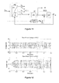
- Figures 5 to 10 illustrate, in graph form, an exemplary operation of the first power transmission network.
- the change in SCR corresponds to a change in network impedance of the AC electrical network, as shown in Figure 7 , and so results in a change in phase difference between the voltages of the AC electrical network and the PCC.
- Figure 6 shows the corresponding changes in real and reactive power exchanged between the AC electrical network and the PCC.
- the processing circuit is capable of accurately determining the network impedance, and therefore the SCR, of the AC electrical network with an error of less than 1%.
- the processing circuit is capable of rapidly determining the network impedance, and therefore the SCR, of the AC electrical network within less than half a cycle (0.01 s).
- the configuration of the processing circuit therefore permits determination of the phase difference, and subsequently use of the phase difference to accurately determine the network impedance of the AC electrical network during the exchange of power between the AC electrical network and the point of common coupling. Furthermore such configuration of the processing circuit permits operation of the converter 20 to be adapted to take into account any variation in the network impedance in order to ensure reliable and stable operation of the first power transmission network. Otherwise not adapting the operation of the converter 20 to take into account any variation in the network impedance could lead to undesirable consequences, such as the occurrence of an undesirable transient overcurrent or a collapse in power transfer between the AC electrical network and the DC electrical network.
- phase locked loop permits continuous and real-time determination of the phase difference between the voltages of the AC electrical network and the PCC during the exchange of power between the AC electrical network and the PCC. This ensures that the first power transmission network may be operated in a reliable and stable manner when the phase difference varies greatly with time.
- the second power transmission network is similar in structure and operation to the first power transmission network of Figure 1 , and like features share the same reference numerals.
- the second power transmission network differs from the first power transmission network in that, in the second power transmission network:
- Configuration of the phase detector and loop filter in this manner enables determination of the phase difference during unbalanced operating conditions of the second power transmission network. This is because the oscillating component associated with the negative sequence component is omitted when determining the phase difference.
- Figures 12 to 16 illustrate, in graph form, an exemplary operation of the second power transmission network.
- the change in SCR corresponds to a change in network impedance of the AC electrical network, as shown in Figure 15 , and so results in a change in phase difference between the voltages of the AC electrical network and the PCC.
- Figure 13 shows the corresponding changes in real and reactive power exchanged between the AC electrical network and the PCC.
- the processing circuit is capable of accurately determining the network impedance, and therefore the SCR, of the AC electrical network with an error of less than 1%.
- the processing circuit is capable of rapidly determining the network impedance, and therefore the SCR, of the AC electrical network.
- a single phase-to-ground fault is applied to one of the phases of the AC electrical network to simulate unbalanced operating conditions of the second power transmission network.
- the converter control reduces its power reference to handle the unbalanced operating conditions. It can be seen from the top graph of Figure 14 that the SCR of the network impedance is increased, as illustrated by the corresponding reduction in real power to approximately 0.5 per unit in the top graph of Figure 13
- the processing circuit of the second power transmission network is capable of accurate and rapid determination of the phase difference during both balanced and unbalanced operating conditions of the second power transmission network, when compared to the processing circuit of the first power transmission network. This is illustrated by the presence of an oscillating component 100 that is caused by the existence of a negative sequence component when the processing circuit of the first power transmission network is used. As mentioned above and as shown in Figure 11 , the processing circuit of the second power transmission network eliminates the oscillating component by only allowing the positive sequence component of the quadrature voltage (Vq + ) to be passed to the loop filter.
- topologies of the converter and the power transmission network are merely chosen to help illustrate the operation of the invention, and that the converter and the power transmission network may be respectively replaced by another converter with a different topology and by another power transmission network with a different topology.
- the AC electrical network may have a single phase or a different plurality of phases. Accordingly the number of converter limbs in the converter may vary to correspond to the number of phases of the AC electrical network.
Landscapes
- Engineering & Computer Science (AREA)
- Power Engineering (AREA)
- Inverter Devices (AREA)
- Ac-Ac Conversion (AREA)
- Measurement Of Resistance Or Impedance (AREA)
Abstract
an AC electrical network connected to a point of common coupling (PCC), the point of common coupling being connectable to a further electrical device, for instance a voltage source converter (VSC);
a processing circuit, including for instance a Phase Locked Loop, configured to receive and process a voltage of the point of common coupling (voltage Vt) to determine a phase difference between the voltages of the AC electrical network and the point of common coupling during an exchange of power between the AC electrical network and the point of common coupling.
Based on this phase difference, an impedance of the AC network can be computed and a control of the exchanged active / reactive power implemented.
In case of an unbalanced three-phase AC system, the negative component can be filtered out.
Description
- This invention relates to a power transmission network.
- In power transmission networks alternative current (AC) power is converted to direct current (DC) power for transmission via overhead lines and/or under-sea cables. This conversion to DC power removes the need to compensate for the AC capacitive load effects imposed by the power transmission medium, i.e. the transmission line or cable, and reduces the cost per kilometre of the lines and/or cables, and thus becomes cost-effective when power needs to be transmitted over a long distance. A converter, such as a voltage source converter, provides the required conversion between AC power and DC power within the power transmission network.
- According to an aspect of the invention, there is provided a power transmission network comprising:
- an AC electrical network connected to a point of common coupling, the point of common coupling being connectable to a further electrical device;
- a processing circuit configured to receive and process a voltage of the point of common coupling to determine a phase difference between the voltages of the AC electrical network and the point of common coupling during an exchange of power between the AC electrical network and the point of common coupling.
- The inclusion of the processing circuit in the power transmission network according to the invention enables determination of the phase difference between the voltages of the AC electrical network and the point of common coupling during an exchange of power between the AC electrical network and the point of common coupling. This in turn permits use of the phase difference to provide information about the electrical characteristics of the power transmission network in order to improve the reliability and stability of the operation of the power transmission network.
- The voltages of the AC electrical network and the point of common coupling may be in-phase prior to the exchange of power between the AC electrical network and the point of common coupling. This results in a more accurate determination of the phase difference between the voltages of the AC electrical network and the point of common coupling during the exchange of power between the AC electrical network and the point of common coupling
- The electrical device, to which the point of common coupling is connected, may vary depending on the operating requirements of the power transmission network. For example, the point of common coupling may be connected to a converter.
- An AC electrical network may include one or more sources, one or more loads and one or more power transmission lines. Thus, the network impedance of the AC electrical network not only may be difficult to determine when the AC electrical network has a complex structure, but also could vary as a result of the interaction(s) between its various components. This in turn could make it difficult to operate the converter in a manner that ensures reliable and stable operation of the power transmission network.
- When the point of common coupling is connected to a converter, the processing circuit may be configured to process the phase difference in combination with the voltage and current of the point of common coupling to determine a network impedance of the AC electrical network. The processing circuit may be configured to process the network impedance to define the operating requirements of the converter, and to operate the converter in accordance with the defined operating requirements.
- The configuration of the processing circuit in this manner permits accurate determination of the network impedance of the AC electrical network during the exchange of power between the AC electrical network and the point of common coupling. Furthermore such configuration of the processing circuit permits operation of the converter to be adapted to take into account any variation in the network impedance in order to ensure reliable and stable operation of the power transmission network. Otherwise not adapting the operation of the converter to take into account any variation in the network impedance could lead to undesirable consequences, such as the occurrence of an undesirable transient overcurrent or a collapse in power transfer in the power transmission network.
- The defined operating requirements of the converter may vary depending on the operating conditions of the power transmission network.
- For example, the processing circuit may be configured to process the network impedance to define the real and/or reactive power exchange requirements of the exchange of power between the AC electrical network and the converter, and to operate the converter in accordance with the defined real and/or reactive power exchange requirements.
- The configuration of the processing circuit to define the reactive power exchange requirements of the exchange of power between the AC electrical network and the converter is particularly useful when the AC electrical network is a weak AC electrical network.
- It will be appreciated that the configuration of the processing circuit according to the invention may vary as long as the processing circuit is capable of receiving and processing a voltage of the point of common coupling to determine a phase difference between the voltages of the AC electrical network and the point of common coupling during an exchange of real power between the AC electrical network and the point of common coupling.
- In embodiments of the invention the processing circuit may be or may include a phase locked loop to receive and process the voltage of the point of common coupling to determine the phase difference between the voltages of the AC electrical network and the point of common coupling. The phase locked loop may include a cascade connection of a phase detector, a loop filter and a first voltage controlled oscillator. The output of the loop filter may be configured to provide a phase difference signal corresponding to the phase difference between the voltages of the AC electrical network and the point of common coupling.
- The use of a phase locked loop permits continuous and real-time determination of the phase difference between the voltages of the AC electrical network and the point of common coupling during the exchange of real power between the AC electrical network and the point of common coupling. This ensures that the power transmission network may be operated in a reliable and stable manner when the phase difference varies greatly with time.
- In such embodiments the phase locked loop may further include a second voltage controlled oscillator. The second voltage controlled oscillator may be configured to lock the phases of the voltages of the AC electrical network and the point of common coupling prior to the exchange of power between the AC electrical network and the point of common coupling. The phase locked loop may be configured to switch between the first and second voltage controlled oscillators.
- The addition of the second voltage controlled oscillator to the phase locked loop not only obviates the need for a single voltage controlled oscillator to perform multiple functions, thus simplifying the structure of the phase locked loop, but also permits the design of each voltage controlled oscillator to be optimised with regard to its respective function
- In further embodiments of the invention the processing circuit may further include a frequency detector configured to receive and process a voltage of the point of common coupling to provide a frequency reference to the voltage controlled oscillator. The frequency detector may be or may include a frequency locked loop.
- The provision of a frequency reference to the voltage controlled oscillator eliminates any error in the determined phase difference that would have been caused by a shift in frequency of the AC electrical network, thus improving the accuracy of the determined phase difference.
- The frequency detector may be configured to clamp the frequency reference to correspond to a nominal frequency of the AC electrical network during the exchange of power between the AC electrical network and the point of common coupling.
- In still further embodiments of the invention the phase detector may be configured to perform a transformation of the received voltage of the point of common coupling to provide a voltage vector consisting of positive and negative sequence components.
- In such embodiments the loop filter may be configured to receive and process only the positive sequence component of the positive and negative sequence components of the voltage vector to determine the phase difference between the voltages of the AC electrical network and the point of common coupling during an exchange of power between the AC electrical network and the point of common coupling. Configuration of the loop filter in this manner enables determination of the phase difference during unbalanced operating conditions of the power transmission network. This is because the oscillating component associated with the negative sequence component is omitted when determining the phase difference.
- Preferred embodiments of the invention will now be described, by way of non-limiting examples, with reference to the accompanying drawings in which:
-
Figure 1 a shows, in schematic form, a power transmission network according to a first embodiment of the invention; -
Figure 1b shows, in schematic form, a converter of the power transmission network ofFigure 1 a; -
Figures 2a and 2b shows, in schematic form, a processing circuit of the power transmission network ofFigure 1 ; -
Figure 2c illustrates the operation of the processing circuit ofFigures 2a and 2b to switch between different voltage controlled oscillators; -
Figure 3 shows, in schematic form, an equivalent representation of the AC side of the power transmission network ofFigure 1 ; -
Figures 4a and 4b illustrate, in graph form, vector diagrams of the voltages of the AC electrical network, point of common coupling and converter of the power transmission network ofFigure 1 ; -
Figures 5 to 10 illustrate, in graph form, an exemplary operation of the power transmission network ofFigure 1 a; -
Figure 11 shows, in schematic form, a processing circuit of a power transmission network according to a second embodiment of the invention; and -
Figures 12 to 16 illustrates, in graph form, an exemplary operation of the power transmission network according to the second embodiment of the invention. - A first power transmission network according to a first embodiment of the invention is shown in
Figure 1 a. - The first power transmission network includes a three-phase AC electrical network, a point of common coupling (PCC), a transformer and a
converter 18. - The
converter 18 includes a plurality ofconverter limbs 20, as shown inFigure 1 b. - Each
converter limb 20 extends between a pair of secondelectrical terminals 19. Eachconverter limb 20 has first andsecond limb portions electrical terminal 25. - Each
limb portion switching elements 26. Eachswitching element 26 includes an active switching device that is connected in antiparallel with a passive current check element. - Each active switching device is in the form of an insulated gate bipolar transistor (IGBT). It is envisaged that, in other embodiments of the invention, each IGBT may be replaced by a gate turn-off thyristor, a field effect transistor, an injection-enhanced gate transistor, an integrated gate commutated thyristor or any other self-commutated switching device. The number of active switching devices in each switching element may vary depending on the required voltage rating of that
switching element 26. - Each passive current check element includes a passive current check device in the form of a diode. It is envisaged that, in other embodiments, each diode may be replaced by any other device that is capable of limiting current flow in only one direction. The number of passive current check devices in each passive current check element may vary depending on the required voltage rating of that passive current check element.
- Each phase of the AC electrical network is connected to the PCC via a first transmission link. The PCC is connected to a primary side of the transformer via a second transmission link.
- The first
electrical terminals 25 of theconverter 20 are connected to a secondary side of the transformer via a third transmission link. In this manner the first electrical terminals of theconverter 20 are respectively connected to a respective phase of the AC electrical network. - The second electrical terminals of each
converter 20 are connected to a DC electrical network carrying a DC voltage of Vdc - The first power transmission network further includes a processing circuit, as shown in
Figures 2a and 2b . - The processing circuit includes a phase locked loop. The phase locked loop includes a cascade connection of a phase detector, a loop filter and a first voltage controlled oscillator. More particularly, an output of the phase detector is in communication with an input of the loop filter, an output of the loop filter is in communication to an input of the first voltage controlled oscillator, and an output of the first voltage controlled oscillator is in communication with an input of the phase detector to form a closed loop.
- The phase detector is configured to receive the voltage Vabc of the PCC and to perform a stationary a-b-c reference frame to a synchronously rotating d-q reference frame transformation of the received voltage of the PCC to provide a voltage vector consisting of synchronously rotating direct and quadrature components Vd,Vq.
- The loop filter is configured to provide a low-pass filtering characteristic to attenuate highfrequency AC components in the synchronously rotating quadrature component Vq of the voltage vector to provide a phase difference signal. In the embodiment shown, the loop filter is constituted by a proportional-integral controller, but it may be replaced by a first-order low-pass filter in other embodiments.
- The first voltage controlled oscillator is configured to receive the phase difference signal and to generate an output AC signal as a function of the received phase difference signal. More particularly, the phase difference signal is added to an integral of a frequency reference ω0 and then processed to reset the phase angle whenever it reaches 2π rad and to keep it between 0 to 2π rad (i.e. 0 to 360°). The output AC signal is fed back to the phase detector.
- The processing circuit further includes a frequency detector configured to receive and process the voltage Vabc of the PCC to provide the frequency reference ω0 to the voltage controlled oscillator. In the embodiment shown, the frequency detector is a frequency locked loop. The frequency detector is further configured to selectively clamp the frequency reference ω0 to correspond to a nominal frequency of the AC electrical network.
- The phase locked loop further includes a second voltage controlled oscillator. The phase locked loop is configured to switch between the first and second voltage controlled oscillators, as illustrated in
Figure 2c . As such only one of the first and second voltage controlled oscillators is switched into the phase locked loop at any one time. - When the second voltage controlled oscillator is switched into the phase locked loop to replace the first voltage controlled oscillator, the output of the loop filter is in communication with an input of the second voltage controlled oscillator, and an output of the second voltage controlled oscillator is in communication with the input of the phase detector to form a closed loop.
- The second voltage controlled oscillator is configured to receive the phase difference signal and to generate an output AC signal as a function of the received phase difference signal. More particularly, the phase difference signal is added to the frequency reference ω0 and then processed by an integral block to provide the output AC signal ωt. The output of the integral block is kept between 0 to 2π rad (i.e. 0 to 360°), and will reset to 0 whenever it reaches 2π. The output AC signal is fed back to the phase detector.
- Operation of the first power transmission network is described as follows, with reference to
Figures 2c to 10 . - The AC electrical network may include one or more sources, one or more loads and one or more power transmission lines. Thus, the network impedance of the AC electrical network not only may be difficult to determine when the AC electrical network has a complex structure, but also could vary as a result of the interaction(s) between its various components. This in turn could make it difficult to operate the
converter 20 in a manner that ensures reliable and stable operation of the first power transmission network. -
Figure 3 shows an equivalent representation of the AC side of the first power transmission network ofFigure 1a . The AC electrical network is represented as a first voltage source with a voltage of Es, and its network impedance is represented as a simple equivalent impedance Zs. Theconverter 20 is represented as a second voltage source with a fundamental frequency phasor Vc. The amplitude and phase angle of the output AC voltage at each first electrical terminal of the second voltage source is assumed to be controllable through any AC voltage control method, such as power synchronisation control (PSC) or vector current control (VCC). The transformer is modelled using its leakage inductance Xc. - The stiffness of the AC electrical network is given by its short circuit ratio (SCR), which is calculated as follows:

- where Vt is the voltage of the PCC;
- Prated is the nominal power rating of the first power transmission network.
- The fundamental apparent power in each first electrical terminal of the
converter 20 is given by:
- where S is the fundamental apparent power [VA] exchanged between the
converter 20 and the AC electrical network; - P is the real power [W] exchanged between the
converter 20 and the AC electrical network; - Q is the reactive power [VAR] exchanged between the
converter 20 and the AC electrical network; -
E s is the voltage of the AC electrical network; -
I is the current flowing between theconverter 20 and the AC electrical network. - The real power P and reactive power Q exchanged between the PCC and the AC electrical network are expressed as follows:

where δ is the phase difference between the voltages of the AC electrical network and the PCC. - It can be seen from the above equations that the values of Vt, Es and δ can be used to control both of the real power P and reactive power Q exchanged between the PCC and the AC electrical network. In addition it can be seen that the maximum power transfer for a given network impedance Zs is when the phase difference δ equals 90 electrical degrees (or 1.57 rad). In practice, the phase difference δ is likely to be less than 90 electrical degrees. If the phase difference δ exceeds 90 electrical degrees (or 1.57 rad), power transmission in the first power transmission network will decrease and could lead to a collapse in power transfer.
- Prior to the exchange of power between the AC electrical network and the PCC, the second voltage controlled oscillator is switched into the phase locked loop, and the first voltage controlled oscillator is switched out of the phase locked loop. Thereafter, the second voltage controlled oscillator is configured to lock the phases of the voltages of the AC electrical network and the PCC. At this time the voltages of the AC electrical network and the PCC are in-phase (as shown in
Figure 4a ), the output of the loop filter is equal to zero in steady-state conditions (i.e. the phase difference between the voltages of the AC electrical network and the PCC is equal to zero) and the output ωt of the second voltage controlled oscillator is equal to ω0t. - When real power is exchanged between the AC electrical network and the PCC, current begins to flow in the network impedance. At this stage the first voltage controlled oscillator (as shown in
Figure 2a ) is switched into the phase locked loop, and the second voltage controlled oscillator (as shown inFigure 2b ) is switched out of the phase locked loop. The output of the second voltage controlled oscillator is utilised as an initial value for the first voltage controlled oscillator, as shown inFigure 2c . This allows the first voltage controlled oscillator to utilise the initial zero phase difference present prior to the exchange of power between the AC electrical network and the PCC. - Once the current begins to flow in the network impedance, the first voltage controlled oscillator adjust the rotational speed of the d-q reference frame, as shown in
Figure 4b , such that the synchronously rotating quadrature component Vq of the voltage vector is forced to zero and ωt is equal to wot + δ. At this time the output of the loop filter is equal to a non-zero value (i.e. the phase difference between the voltages of the AC electrical network and the PCC is a non-zero value). In this manner the output of the loop filter is configured to provide a phase difference signal corresponding to the phase difference between the voltages of the AC electrical network and the PCC. - As such the phase locked loop of the processing circuit is capable of receiving and processing the voltage of the PCC to determine the phase difference between the voltages of the AC electrical network and the PCC.
- Using the above equations, the processing circuit processes the phase difference in combination with the voltage and current of the PCC to determine the value of the network impedance of the AC electrical network. In determining the value of the network impedance of the AC electrical network, the voltages of the AC electrical network and the PCC are assumed to be the same since the resistance of the network impedance is very low.
- Thereafter, the processing circuit processes the network impedance to define the operating requirements of the
converter 20, and to operate theconverter 20 in accordance with the defined operating requirements. For example, the processing circuit may process the network impedance to define the real and/or reactive power exchange requirements of the exchange of power between the AC electrical network and theconverter 20, and to operate theconverter 20 in accordance with the defined real and/or reactive power exchange requirements. The configuration of the processing circuit to define the reactive power exchange requirements of the exchange of power between the AC electrical network and theconverter 20 is particularly useful when the AC electrical network is a weak AC electrical network. - During the exchange of power between the AC electrical network and the PCC, the frequency detector clamp the frequency reference ω0 to correspond to a nominal frequency of the AC electrical network. The provision of the frequency reference to the first voltage controlled oscillator eliminates any error in the determined phase difference that would have been caused by a shift in frequency of the AC electrical network, thus improving the accuracy of the determined phase difference.
-
Figures 5 to 10 illustrate, in graph form, an exemplary operation of the first power transmission network. - In this exemplary operation, the DC power of the first power transmission network is ramped up at t = 0.5 s from zero towards a rated power of 24MW (1.0 per unit). Meanwhile the
converter 20 is controlled to maintain a constant AC voltage at each of its first electrical terminals, as shown inFigure 5 . - From t = 0 s to t = 1.2 s, the network impedance has a SCR of 4. Thereafter, the SCR of the network impedance is changed to 3 at t = 1.2 s, to 2 at t = 1.8 s and to 1.5 at t = 2.3 s to simulate a variation in the network impedance, as shown in
Figure 8 . The change in SCR corresponds to a change in network impedance of the AC electrical network, as shown inFigure 7 , and so results in a change in phase difference between the voltages of the AC electrical network and the PCC.Figure 6 shows the corresponding changes in real and reactive power exchanged between the AC electrical network and the PCC. - It can be seen from
Figure 8 that the processing circuit is capable of accurately determining the network impedance, and therefore the SCR, of the AC electrical network with an error of less than 1%. In addition it can be seen fromFigures 9 and 10 that, after the change in SCR of the network impedance, the processing circuit is capable of rapidly determining the network impedance, and therefore the SCR, of the AC electrical network within less than half a cycle (0.01 s). - The configuration of the processing circuit, as shown in
Figures 2a and 2b , therefore permits determination of the phase difference, and subsequently use of the phase difference to accurately determine the network impedance of the AC electrical network during the exchange of power between the AC electrical network and the point of common coupling. Furthermore such configuration of the processing circuit permits operation of theconverter 20 to be adapted to take into account any variation in the network impedance in order to ensure reliable and stable operation of the first power transmission network. Otherwise not adapting the operation of theconverter 20 to take into account any variation in the network impedance could lead to undesirable consequences, such as the occurrence of an undesirable transient overcurrent or a collapse in power transfer between the AC electrical network and the DC electrical network. - In addition the use of the phase locked loop permits continuous and real-time determination of the phase difference between the voltages of the AC electrical network and the PCC during the exchange of power between the AC electrical network and the PCC. This ensures that the first power transmission network may be operated in a reliable and stable manner when the phase difference varies greatly with time.
- There is provided a second power transmission network according to a second embodiment of the invention. The second power transmission network is similar in structure and operation to the first power transmission network of
Figure 1 , and like features share the same reference numerals. - The second power transmission network differs from the first power transmission network in that, in the second power transmission network:
- the phase detector is configured to perform a stationary a-b-c reference frame to a synchronously rotating d-q reference frame transformation of the received voltage of the point of common coupling to provide a voltage vector consisting of positive and negative sequence components;
- the loop filter is configured to receive and process only the positive sequence component of the positive and negative sequence components of the voltage vector.
- Configuration of the phase detector and loop filter in this manner enables determination of the phase difference during unbalanced operating conditions of the second power transmission network. This is because the oscillating component associated with the negative sequence component is omitted when determining the phase difference.
-
Figures 12 to 16 illustrate, in graph form, an exemplary operation of the second power transmission network. - In this exemplary operation, the DC power of the first power transmission network is ramped up at t = 0.2 s from zero towards a rated power of 24MW (1.0 per unit). Meanwhile the
converter 20 is controlled to maintain a constant AC voltage at each of its first electrical terminals, as shown inFigure 12 . - From t = 0 s to t = 0.8 s, the network impedance has a SCR of 4. Thereafter, the SCR of the network impedance is changed to 1.5 at t = 0.8 s to simulate a variation in the network impedance, as shown in
Figure 14 . The change in SCR corresponds to a change in network impedance of the AC electrical network, as shown inFigure 15 , and so results in a change in phase difference between the voltages of the AC electrical network and the PCC.Figure 13 shows the corresponding changes in real and reactive power exchanged between the AC electrical network and the PCC. - It can be seen from
Figure 14 that the processing circuit is capable of accurately determining the network impedance, and therefore the SCR, of the AC electrical network with an error of less than 1%. In addition it can be seen fromFigure 15 that, after the change in SCR of the network impedance, the processing circuit is capable of rapidly determining the network impedance, and therefore the SCR, of the AC electrical network. - At t = 1 s, a single phase-to-ground fault is applied to one of the phases of the AC electrical network to simulate unbalanced operating conditions of the second power transmission network. In response the converter control reduces its power reference to handle the unbalanced operating conditions. It can be seen from the top graph of
Figure 14 that the SCR of the network impedance is increased, as illustrated by the corresponding reduction in real power to approximately 0.5 per unit in the top graph ofFigure 13 - It can be seen from
Figure 16 that the processing circuit of the second power transmission network is capable of accurate and rapid determination of the phase difference during both balanced and unbalanced operating conditions of the second power transmission network, when compared to the processing circuit of the first power transmission network. This is illustrated by the presence of anoscillating component 100 that is caused by the existence of a negative sequence component when the processing circuit of the first power transmission network is used. As mentioned above and as shown inFigure 11 , the processing circuit of the second power transmission network eliminates the oscillating component by only allowing the positive sequence component of the quadrature voltage (Vq+) to be passed to the loop filter. - It will be appreciated that the properties of the converter and the power transmission network are merely chosen to help illustrate the operation of the invention, and may vary depending on the requirements of the associated power application.
- It will be further appreciated that the topologies of the converter and the power transmission network are merely chosen to help illustrate the operation of the invention, and that the converter and the power transmission network may be respectively replaced by another converter with a different topology and by another power transmission network with a different topology.
- In other embodiments of the invention it is envisaged that, instead of having three phases, the AC electrical network may have a single phase or a different plurality of phases. Accordingly the number of converter limbs in the converter may vary to correspond to the number of phases of the AC electrical network.
Claims (13)
- A power transmission network comprising:an AC electrical network connected to a point of common coupling, the point of common coupling being connectable to a further electrical device;a processing circuit configured to receive and process a voltage of the point of common coupling to determine a phase difference between the voltages of the AC electrical network and the point of common coupling during an exchange of power between the AC electrical network and the point of common coupling.
- A power transmission network according to Claim 1 wherein the voltages of the AC electrical network and the point of common coupling are in-phase prior to the exchange of power between the AC electrical network and the point of common coupling.
- A power transmission network according to any preceding claim wherein the point of common coupling is connected to a converter.
- A power transmission network according to Claim 3 wherein the processing circuit is configured to process the phase difference in combination with the voltage and current of the point of common coupling to determine a network impedance of the AC electrical network, to process the network impedance to define the operating requirements of the converter, and to operate the converter in accordance with the defined operating requirements.
- A power transmission network according to Claim 4 wherein the processing circuit is configured to process the network impedance to define the real and/or reactive power exchange requirements of the exchange of power between the AC electrical network and the converter, and to operate the converter in accordance with the defined real and/or reactive power exchange requirements.
- A power transmission network according to any preceding claim wherein the processing circuit is or includes a phase locked loop to receive and process the voltage of the point of common coupling to determine the phase difference between the voltages of the AC electrical network and the point of common coupling.
- A power transmission network according to Claim 6 wherein the phase locked loop includes a cascade connection of a phase detector, a loop filter and a first voltage controlled oscillator, an output of the loop filter being configured to provide a phase difference signal corresponding to the phase difference between the voltages of the AC electrical network and the point of common coupling.
- A power transmission network according to Claim 7 wherein the phase locked loop further includes a second voltage controlled oscillator, the second voltage controlled oscillator is configured to lock the phases of the voltages of the AC electrical network and the point of common coupling prior to the exchange of power between the AC electrical network and the point of common coupling, and the phase locked loop is configured to switch between the first and second voltage controlled oscillators.
- A power transmission network according to Claim 7 or Claim 8 wherein the processing circuit further includes a frequency detector configured to receive and process a voltage of the point of common coupling to provide a frequency reference to the voltage controlled oscillator.
- A power transmission network according to Claim 9 wherein the frequency detector is or includes a frequency locked loop.
- A power transmission network according to Claim 9 or Claim 10 wherein the frequency detector is configured to clamp the frequency reference to correspond to a nominal frequency of the AC electrical network during the exchange of power between the AC electrical network and the point of common coupling.
- A power transmission network according to any of Claims 7 to 11 wherein the phase detector is configured to perform a transformation of the received voltage of the point of common coupling to provide a voltage vector consisting of positive and negative sequence components.
- A power transmission network according to Claim 12 wherein the loop filter is configured to receive and process only the positive sequence component of the positive and negative sequence components of the voltage vector to determine the phase difference between the voltages of the AC electrical network and the point of common coupling during an exchange of power between the AC electrical network and the point of common coupling.
Priority Applications (4)
| Application Number | Priority Date | Filing Date | Title |
|---|---|---|---|
| EP14275133.8A EP2955812B1 (en) | 2014-06-09 | 2014-06-09 | Power transmission network |
| PCT/EP2015/062718 WO2015189151A1 (en) | 2014-06-09 | 2015-06-08 | Power transmission network |
| US15/316,522 US10483762B2 (en) | 2014-06-09 | 2015-06-08 | Power transmission network |
| CN201580031136.1A CN106464261B (en) | 2014-06-09 | 2015-06-08 | transmission network |
Applications Claiming Priority (1)
| Application Number | Priority Date | Filing Date | Title |
|---|---|---|---|
| EP14275133.8A EP2955812B1 (en) | 2014-06-09 | 2014-06-09 | Power transmission network |
Publications (2)
| Publication Number | Publication Date |
|---|---|
| EP2955812A1 true EP2955812A1 (en) | 2015-12-16 |
| EP2955812B1 EP2955812B1 (en) | 2022-07-27 |
Family
ID=50933104
Family Applications (1)
| Application Number | Title | Priority Date | Filing Date |
|---|---|---|---|
| EP14275133.8A Active EP2955812B1 (en) | 2014-06-09 | 2014-06-09 | Power transmission network |
Country Status (4)
| Country | Link |
|---|---|
| US (1) | US10483762B2 (en) |
| EP (1) | EP2955812B1 (en) |
| CN (1) | CN106464261B (en) |
| WO (1) | WO2015189151A1 (en) |
Cited By (1)
| Publication number | Priority date | Publication date | Assignee | Title |
|---|---|---|---|---|
| CN112713609A (en) * | 2020-12-17 | 2021-04-27 | 华中科技大学 | Impedance prediction method of voltage source type converter under variable working point |
Families Citing this family (2)
| Publication number | Priority date | Publication date | Assignee | Title |
|---|---|---|---|---|
| CN108471131B (en) * | 2018-03-21 | 2020-02-07 | 华北电力大学 | Method and system for evaluating stability of flexible direct current transmission system |
| US11901734B2 (en) | 2021-11-30 | 2024-02-13 | Vestas Wind Systems A/S | Grid side inverter system arranged for controlling current injection when a phase locked loop controller is misaligned |
Citations (3)
| Publication number | Priority date | Publication date | Assignee | Title |
|---|---|---|---|---|
| EP0152595A1 (en) * | 1981-09-22 | 1985-08-28 | Matsumura, Susumu | Control apparatus for D.C. power transmission system |
| US20130166090A1 (en) * | 2011-12-22 | 2013-06-27 | General Electric Company | Power converter and methods of controlling the same |
| EP2698920A1 (en) * | 2012-08-13 | 2014-02-19 | ABB Technology AG | Phase-locked loop |
Family Cites Families (6)
| Publication number | Priority date | Publication date | Assignee | Title |
|---|---|---|---|---|
| US5642007A (en) * | 1994-12-30 | 1997-06-24 | Westinghouse Electric Corporation | Series compensator inserting real and reactive impedance into electric power system for damping power oscillations |
| US6993107B2 (en) * | 2001-01-16 | 2006-01-31 | International Business Machines Corporation | Analog unidirectional serial link architecture |
| US7928780B1 (en) * | 2009-09-29 | 2011-04-19 | General Electric Company | Phase-locked-loop circuit |
| US8014181B2 (en) * | 2009-09-29 | 2011-09-06 | General Electric Company | Power conversion control system |
| US20110128054A1 (en) * | 2009-11-30 | 2011-06-02 | Rockwell Automation Technologies, Inc. | Phase lock loop with tracking filter for synchronizing an electric grid |
| CN102136738B (en) * | 2011-04-25 | 2013-01-23 | 东北电力大学 | Control method of grid-connected inverter of large-scale grid-connected photovoltaic power station |
-
2014
- 2014-06-09 EP EP14275133.8A patent/EP2955812B1/en active Active
-
2015
- 2015-06-08 US US15/316,522 patent/US10483762B2/en active Active
- 2015-06-08 CN CN201580031136.1A patent/CN106464261B/en active Active
- 2015-06-08 WO PCT/EP2015/062718 patent/WO2015189151A1/en not_active Ceased
Patent Citations (3)
| Publication number | Priority date | Publication date | Assignee | Title |
|---|---|---|---|---|
| EP0152595A1 (en) * | 1981-09-22 | 1985-08-28 | Matsumura, Susumu | Control apparatus for D.C. power transmission system |
| US20130166090A1 (en) * | 2011-12-22 | 2013-06-27 | General Electric Company | Power converter and methods of controlling the same |
| EP2698920A1 (en) * | 2012-08-13 | 2014-02-19 | ABB Technology AG | Phase-locked loop |
Non-Patent Citations (2)
| Title |
|---|
| MINAMBRES V ET AL: "Comparison of controllers for a three-phase Phase Locked Loop system under distorted conditions", COMPATIBILITY AND POWER ELECTRONICS, 2009. CPE '09, IEEE, PISCATAWAY, NJ, USA, 20 May 2009 (2009-05-20), pages 79 - 85, XP031483897, ISBN: 978-1-4244-2855-7 * |
| ROCABERT J ET AL: "Control of Power Converters in AC Microgrids", IEEE TRANSACTIONS ON POWER ELECTRONICS, INSTITUTE OF ELECTRICAL AND ELECTRONICS ENGINEERS, USA, vol. 27, no. 11, 30 November 2012 (2012-11-30), pages 4734 - 4749, XP011454774, ISSN: 0885-8993, DOI: 10.1109/TPEL.2012.2199334 * |
Cited By (2)
| Publication number | Priority date | Publication date | Assignee | Title |
|---|---|---|---|---|
| CN112713609A (en) * | 2020-12-17 | 2021-04-27 | 华中科技大学 | Impedance prediction method of voltage source type converter under variable working point |
| CN112713609B (en) * | 2020-12-17 | 2022-08-05 | 华中科技大学 | Impedance prediction method of voltage source type converter under variable working point |
Also Published As
| Publication number | Publication date |
|---|---|
| US10483762B2 (en) | 2019-11-19 |
| CN106464261A (en) | 2017-02-22 |
| EP2955812B1 (en) | 2022-07-27 |
| WO2015189151A1 (en) | 2015-12-17 |
| CN106464261B (en) | 2020-06-23 |
| US20170141574A1 (en) | 2017-05-18 |
Similar Documents
| Publication | Publication Date | Title |
|---|---|---|
| KR101494453B1 (en) | harmonic current suppression method and harmonic current suppression device of power conversion device | |
| Suul et al. | Voltage-sensor-less synchronization to unbalanced grids by frequency-adaptive virtual flux estimation | |
| Aithal et al. | Performance of an electrical distribution network with Soft Open Point during a grid side AC fault | |
| US10199954B2 (en) | Voltage source converter | |
| US10389129B2 (en) | Method and control system for controlling a voltage source converter using power-synchronization control | |
| JP6585713B2 (en) | Uninterruptible power system | |
| CN115480103B (en) | A grid impedance detection method and grid-connected system | |
| KR102485705B1 (en) | Method for controlling three phase equivalent voltage of multilevel inverter | |
| US10539629B2 (en) | Programmable alternating current (AC) load having regenerative and dissipative modes | |
| CN104980040A (en) | Power converterpower converting apparatus control device of power converterpower converting apparatus and control method of power converterpower converting apparatus | |
| Reyes et al. | Decoupled double synchronous reference frame current controller for unbalanced grid voltage conditions | |
| EP2955812B1 (en) | Power transmission network | |
| Espina et al. | Active power angle droop control per phase for unbalanced 4-wire microgrids | |
| Darbandi et al. | Effect of short-circuit ratio and current limiting on the stability of a virtual synchronous machine type gridforming converter | |
| Liu et al. | Control and implementation of converter based ac transmission line emulation | |
| EP3432461A1 (en) | Power conversion device | |
| Mohammed et al. | Performance evaluation of R-UPQC and L-UPQC based on a novel voltage detection algorithm | |
| Suul et al. | Power control of VSC HVDC converters for limiting the influence of AC unbalanced faults on multi-terminal DC grids | |
| Miskovic et al. | Robust sensorless control of grid connected converters with LCL line filters using frequency adaptive observers as AC voltage estimators | |
| Støylen et al. | Laboratory demonstration of an offshore grid in the North Sea with dc droop control | |
| Suul et al. | Frequency-adaptive virtual flux estimation for grid synchronization under unbalanced conditions | |
| Dendouga et al. | Robustness evaluation of vector control of induction motor fed by SVM matrix converter | |
| De et al. | An active shunt compensator for reactive, unbalanced and harmonic loads under balanced and unbalanced grid voltage conditions | |
| Jahromi et al. | Control strategy for a high power DC transformer with soft switching scheme for mining applications | |
| Bosch et al. | Hybrid filter with an optimized switching method of the compensation capacitors and predictive active filter control |
Legal Events
| Date | Code | Title | Description |
|---|---|---|---|
| PUAI | Public reference made under article 153(3) epc to a published international application that has entered the european phase |
Free format text: ORIGINAL CODE: 0009012 |
|
| AK | Designated contracting states |
Kind code of ref document: A1 Designated state(s): AL AT BE BG CH CY CZ DE DK EE ES FI FR GB GR HR HU IE IS IT LI LT LU LV MC MK MT NL NO PL PT RO RS SE SI SK SM TR |
|
| AX | Request for extension of the european patent |
Extension state: BA ME |
|
| 17P | Request for examination filed |
Effective date: 20160429 |
|
| RBV | Designated contracting states (corrected) |
Designated state(s): AL AT BE BG CH CY CZ DE DK EE ES FI FR GB GR HR HU IE IS IT LI LT LU LV MC MK MT NL NO PL PT RO RS SE SI SK SM TR |
|
| RAP1 | Party data changed (applicant data changed or rights of an application transferred) |
Owner name: GENERAL ELECTRIC TECHNOLOGY GMBH |
|
| STAA | Information on the status of an ep patent application or granted ep patent |
Free format text: STATUS: EXAMINATION IS IN PROGRESS |
|
| 17Q | First examination report despatched |
Effective date: 20180801 |
|
| RIC1 | Information provided on ipc code assigned before grant |
Ipc: H02M 7/757 20060101ALN20211209BHEP Ipc: H03L 7/087 20060101ALI20211209BHEP Ipc: H03L 7/14 20060101ALI20211209BHEP Ipc: H03L 7/08 20060101ALI20211209BHEP Ipc: H02J 3/08 20060101ALI20211209BHEP Ipc: H02J 3/06 20060101ALI20211209BHEP Ipc: H02J 3/36 20060101AFI20211209BHEP |
|
| GRAP | Despatch of communication of intention to grant a patent |
Free format text: ORIGINAL CODE: EPIDOSNIGR1 |
|
| STAA | Information on the status of an ep patent application or granted ep patent |
Free format text: STATUS: GRANT OF PATENT IS INTENDED |
|
| INTG | Intention to grant announced |
Effective date: 20220125 |
|
| GRAS | Grant fee paid |
Free format text: ORIGINAL CODE: EPIDOSNIGR3 |
|
| GRAA | (expected) grant |
Free format text: ORIGINAL CODE: 0009210 |
|
| STAA | Information on the status of an ep patent application or granted ep patent |
Free format text: STATUS: THE PATENT HAS BEEN GRANTED |
|
| AK | Designated contracting states |
Kind code of ref document: B1 Designated state(s): AL AT BE BG CH CY CZ DE DK EE ES FI FR GB GR HR HU IE IS IT LI LT LU LV MC MK MT NL NO PL PT RO RS SE SI SK SM TR |
|
| REG | Reference to a national code |
Ref country code: CH Ref legal event code: EP |
|
| REG | Reference to a national code |
Ref country code: DE Ref legal event code: R096 Ref document number: 602014084391 Country of ref document: DE |
|
| REG | Reference to a national code |
Ref country code: AT Ref legal event code: REF Ref document number: 1507731 Country of ref document: AT Kind code of ref document: T Effective date: 20220815 |
|
| REG | Reference to a national code |
Ref country code: IE Ref legal event code: FG4D |
|
| REG | Reference to a national code |
Ref country code: SE Ref legal event code: TRGR |
|
| REG | Reference to a national code |
Ref country code: LT Ref legal event code: MG9D |
|
| REG | Reference to a national code |
Ref country code: NL Ref legal event code: MP Effective date: 20220727 |
|
| PG25 | Lapsed in a contracting state [announced via postgrant information from national office to epo] |
Ref country code: RS Free format text: LAPSE BECAUSE OF FAILURE TO SUBMIT A TRANSLATION OF THE DESCRIPTION OR TO PAY THE FEE WITHIN THE PRESCRIBED TIME-LIMIT Effective date: 20220727 Ref country code: PT Free format text: LAPSE BECAUSE OF FAILURE TO SUBMIT A TRANSLATION OF THE DESCRIPTION OR TO PAY THE FEE WITHIN THE PRESCRIBED TIME-LIMIT Effective date: 20221128 Ref country code: NO Free format text: LAPSE BECAUSE OF FAILURE TO SUBMIT A TRANSLATION OF THE DESCRIPTION OR TO PAY THE FEE WITHIN THE PRESCRIBED TIME-LIMIT Effective date: 20221027 Ref country code: NL Free format text: LAPSE BECAUSE OF FAILURE TO SUBMIT A TRANSLATION OF THE DESCRIPTION OR TO PAY THE FEE WITHIN THE PRESCRIBED TIME-LIMIT Effective date: 20220727 Ref country code: LV Free format text: LAPSE BECAUSE OF FAILURE TO SUBMIT A TRANSLATION OF THE DESCRIPTION OR TO PAY THE FEE WITHIN THE PRESCRIBED TIME-LIMIT Effective date: 20220727 Ref country code: LT Free format text: LAPSE BECAUSE OF FAILURE TO SUBMIT A TRANSLATION OF THE DESCRIPTION OR TO PAY THE FEE WITHIN THE PRESCRIBED TIME-LIMIT Effective date: 20220727 Ref country code: FI Free format text: LAPSE BECAUSE OF FAILURE TO SUBMIT A TRANSLATION OF THE DESCRIPTION OR TO PAY THE FEE WITHIN THE PRESCRIBED TIME-LIMIT Effective date: 20220727 Ref country code: ES Free format text: LAPSE BECAUSE OF FAILURE TO SUBMIT A TRANSLATION OF THE DESCRIPTION OR TO PAY THE FEE WITHIN THE PRESCRIBED TIME-LIMIT Effective date: 20220727 |
|
| REG | Reference to a national code |
Ref country code: AT Ref legal event code: MK05 Ref document number: 1507731 Country of ref document: AT Kind code of ref document: T Effective date: 20220727 |
|
| PG25 | Lapsed in a contracting state [announced via postgrant information from national office to epo] |
Ref country code: PL Free format text: LAPSE BECAUSE OF FAILURE TO SUBMIT A TRANSLATION OF THE DESCRIPTION OR TO PAY THE FEE WITHIN THE PRESCRIBED TIME-LIMIT Effective date: 20220727 Ref country code: IS Free format text: LAPSE BECAUSE OF FAILURE TO SUBMIT A TRANSLATION OF THE DESCRIPTION OR TO PAY THE FEE WITHIN THE PRESCRIBED TIME-LIMIT Effective date: 20221127 Ref country code: HR Free format text: LAPSE BECAUSE OF FAILURE TO SUBMIT A TRANSLATION OF THE DESCRIPTION OR TO PAY THE FEE WITHIN THE PRESCRIBED TIME-LIMIT Effective date: 20220727 Ref country code: GR Free format text: LAPSE BECAUSE OF FAILURE TO SUBMIT A TRANSLATION OF THE DESCRIPTION OR TO PAY THE FEE WITHIN THE PRESCRIBED TIME-LIMIT Effective date: 20221028 |
|
| PG25 | Lapsed in a contracting state [announced via postgrant information from national office to epo] |
Ref country code: SM Free format text: LAPSE BECAUSE OF FAILURE TO SUBMIT A TRANSLATION OF THE DESCRIPTION OR TO PAY THE FEE WITHIN THE PRESCRIBED TIME-LIMIT Effective date: 20220727 Ref country code: RO Free format text: LAPSE BECAUSE OF FAILURE TO SUBMIT A TRANSLATION OF THE DESCRIPTION OR TO PAY THE FEE WITHIN THE PRESCRIBED TIME-LIMIT Effective date: 20220727 Ref country code: DK Free format text: LAPSE BECAUSE OF FAILURE TO SUBMIT A TRANSLATION OF THE DESCRIPTION OR TO PAY THE FEE WITHIN THE PRESCRIBED TIME-LIMIT Effective date: 20220727 Ref country code: CZ Free format text: LAPSE BECAUSE OF FAILURE TO SUBMIT A TRANSLATION OF THE DESCRIPTION OR TO PAY THE FEE WITHIN THE PRESCRIBED TIME-LIMIT Effective date: 20220727 Ref country code: AT Free format text: LAPSE BECAUSE OF FAILURE TO SUBMIT A TRANSLATION OF THE DESCRIPTION OR TO PAY THE FEE WITHIN THE PRESCRIBED TIME-LIMIT Effective date: 20220727 |
|
| REG | Reference to a national code |
Ref country code: DE Ref legal event code: R097 Ref document number: 602014084391 Country of ref document: DE |
|
| PG25 | Lapsed in a contracting state [announced via postgrant information from national office to epo] |
Ref country code: SK Free format text: LAPSE BECAUSE OF FAILURE TO SUBMIT A TRANSLATION OF THE DESCRIPTION OR TO PAY THE FEE WITHIN THE PRESCRIBED TIME-LIMIT Effective date: 20220727 Ref country code: EE Free format text: LAPSE BECAUSE OF FAILURE TO SUBMIT A TRANSLATION OF THE DESCRIPTION OR TO PAY THE FEE WITHIN THE PRESCRIBED TIME-LIMIT Effective date: 20220727 |
|
| PLBE | No opposition filed within time limit |
Free format text: ORIGINAL CODE: 0009261 |
|
| STAA | Information on the status of an ep patent application or granted ep patent |
Free format text: STATUS: NO OPPOSITION FILED WITHIN TIME LIMIT |
|
| P01 | Opt-out of the competence of the unified patent court (upc) registered |
Effective date: 20230522 |
|
| PG25 | Lapsed in a contracting state [announced via postgrant information from national office to epo] |
Ref country code: AL Free format text: LAPSE BECAUSE OF FAILURE TO SUBMIT A TRANSLATION OF THE DESCRIPTION OR TO PAY THE FEE WITHIN THE PRESCRIBED TIME-LIMIT Effective date: 20220727 |
|
| 26N | No opposition filed |
Effective date: 20230502 |
|
| PG25 | Lapsed in a contracting state [announced via postgrant information from national office to epo] |
Ref country code: SI Free format text: LAPSE BECAUSE OF FAILURE TO SUBMIT A TRANSLATION OF THE DESCRIPTION OR TO PAY THE FEE WITHIN THE PRESCRIBED TIME-LIMIT Effective date: 20220727 |
|
| PG25 | Lapsed in a contracting state [announced via postgrant information from national office to epo] |
Ref country code: MC Free format text: LAPSE BECAUSE OF FAILURE TO SUBMIT A TRANSLATION OF THE DESCRIPTION OR TO PAY THE FEE WITHIN THE PRESCRIBED TIME-LIMIT Effective date: 20220727 |
|
| PG25 | Lapsed in a contracting state [announced via postgrant information from national office to epo] |
Ref country code: MC Free format text: LAPSE BECAUSE OF FAILURE TO SUBMIT A TRANSLATION OF THE DESCRIPTION OR TO PAY THE FEE WITHIN THE PRESCRIBED TIME-LIMIT Effective date: 20220727 |
|
| REG | Reference to a national code |
Ref country code: CH Ref legal event code: PL |
|
| REG | Reference to a national code |
Ref country code: BE Ref legal event code: MM Effective date: 20230630 |
|
| PG25 | Lapsed in a contracting state [announced via postgrant information from national office to epo] |
Ref country code: LU Free format text: LAPSE BECAUSE OF NON-PAYMENT OF DUE FEES Effective date: 20230609 |
|
| REG | Reference to a national code |
Ref country code: IE Ref legal event code: MM4A |
|
| PG25 | Lapsed in a contracting state [announced via postgrant information from national office to epo] |
Ref country code: LU Free format text: LAPSE BECAUSE OF NON-PAYMENT OF DUE FEES Effective date: 20230609 |
|
| PG25 | Lapsed in a contracting state [announced via postgrant information from national office to epo] |
Ref country code: IE Free format text: LAPSE BECAUSE OF NON-PAYMENT OF DUE FEES Effective date: 20230609 |
|
| PG25 | Lapsed in a contracting state [announced via postgrant information from national office to epo] |
Ref country code: IE Free format text: LAPSE BECAUSE OF NON-PAYMENT OF DUE FEES Effective date: 20230609 Ref country code: CH Free format text: LAPSE BECAUSE OF NON-PAYMENT OF DUE FEES Effective date: 20230630 |
|
| PG25 | Lapsed in a contracting state [announced via postgrant information from national office to epo] |
Ref country code: IT Free format text: LAPSE BECAUSE OF FAILURE TO SUBMIT A TRANSLATION OF THE DESCRIPTION OR TO PAY THE FEE WITHIN THE PRESCRIBED TIME-LIMIT Effective date: 20220727 Ref country code: FR Free format text: LAPSE BECAUSE OF NON-PAYMENT OF DUE FEES Effective date: 20230630 Ref country code: BE Free format text: LAPSE BECAUSE OF NON-PAYMENT OF DUE FEES Effective date: 20230630 |
|
| PG25 | Lapsed in a contracting state [announced via postgrant information from national office to epo] |
Ref country code: BG Free format text: LAPSE BECAUSE OF FAILURE TO SUBMIT A TRANSLATION OF THE DESCRIPTION OR TO PAY THE FEE WITHIN THE PRESCRIBED TIME-LIMIT Effective date: 20220727 |
|
| PG25 | Lapsed in a contracting state [announced via postgrant information from national office to epo] |
Ref country code: BG Free format text: LAPSE BECAUSE OF FAILURE TO SUBMIT A TRANSLATION OF THE DESCRIPTION OR TO PAY THE FEE WITHIN THE PRESCRIBED TIME-LIMIT Effective date: 20220727 |
|
| PGFP | Annual fee paid to national office [announced via postgrant information from national office to epo] |
Ref country code: DE Payment date: 20250520 Year of fee payment: 12 |
|
| PGFP | Annual fee paid to national office [announced via postgrant information from national office to epo] |
Ref country code: GB Payment date: 20250520 Year of fee payment: 12 |
|
| PG25 | Lapsed in a contracting state [announced via postgrant information from national office to epo] |
Ref country code: CY Free format text: LAPSE BECAUSE OF FAILURE TO SUBMIT A TRANSLATION OF THE DESCRIPTION OR TO PAY THE FEE WITHIN THE PRESCRIBED TIME-LIMIT; INVALID AB INITIO Effective date: 20140609 |
|
| PGFP | Annual fee paid to national office [announced via postgrant information from national office to epo] |
Ref country code: SE Payment date: 20250520 Year of fee payment: 12 |
|
| PG25 | Lapsed in a contracting state [announced via postgrant information from national office to epo] |
Ref country code: HU Free format text: LAPSE BECAUSE OF FAILURE TO SUBMIT A TRANSLATION OF THE DESCRIPTION OR TO PAY THE FEE WITHIN THE PRESCRIBED TIME-LIMIT; INVALID AB INITIO Effective date: 20140609 |
|
| PG25 | Lapsed in a contracting state [announced via postgrant information from national office to epo] |
Ref country code: TR Free format text: LAPSE BECAUSE OF FAILURE TO SUBMIT A TRANSLATION OF THE DESCRIPTION OR TO PAY THE FEE WITHIN THE PRESCRIBED TIME-LIMIT Effective date: 20220727 |