EP2955700A2 - Automated emergency response systems for a vehicle - Google Patents
Automated emergency response systems for a vehicle Download PDFInfo
- Publication number
- EP2955700A2 EP2955700A2 EP15172186.7A EP15172186A EP2955700A2 EP 2955700 A2 EP2955700 A2 EP 2955700A2 EP 15172186 A EP15172186 A EP 15172186A EP 2955700 A2 EP2955700 A2 EP 2955700A2
- Authority
- EP
- European Patent Office
- Prior art keywords
- vehicle
- storage media
- computer storage
- identifying
- recited
- Prior art date
- Legal status (The legal status is an assumption and is not a legal conclusion. Google has not performed a legal analysis and makes no representation as to the accuracy of the status listed.)
- Withdrawn
Links
Images


Classifications
-
- B—PERFORMING OPERATIONS; TRANSPORTING
- B60—VEHICLES IN GENERAL
- B60R—VEHICLES, VEHICLE FITTINGS, OR VEHICLE PARTS, NOT OTHERWISE PROVIDED FOR
- B60R11/00—Arrangements for holding or mounting articles, not otherwise provided for
- B60R11/04—Mounting of cameras operative during drive; Arrangement of controls thereof relative to the vehicle
-
- G—PHYSICS
- G07—CHECKING-DEVICES
- G07C—TIME OR ATTENDANCE REGISTERS; REGISTERING OR INDICATING THE WORKING OF MACHINES; GENERATING RANDOM NUMBERS; VOTING OR LOTTERY APPARATUS; ARRANGEMENTS, SYSTEMS OR APPARATUS FOR CHECKING NOT PROVIDED FOR ELSEWHERE
- G07C5/00—Registering or indicating the working of vehicles
- G07C5/08—Registering or indicating performance data other than driving, working, idle, or waiting time, with or without registering driving, working, idle or waiting time
- G07C5/0841—Registering performance data
- G07C5/085—Registering performance data using electronic data carriers
-
- B—PERFORMING OPERATIONS; TRANSPORTING
- B60—VEHICLES IN GENERAL
- B60W—CONJOINT CONTROL OF VEHICLE SUB-UNITS OF DIFFERENT TYPE OR DIFFERENT FUNCTION; CONTROL SYSTEMS SPECIALLY ADAPTED FOR HYBRID VEHICLES; ROAD VEHICLE DRIVE CONTROL SYSTEMS FOR PURPOSES NOT RELATED TO THE CONTROL OF A PARTICULAR SUB-UNIT
- B60W30/00—Purposes of road vehicle drive control systems not related to the control of a particular sub-unit, e.g. of systems using conjoint control of vehicle sub-units
- B60W30/06—Automatic manoeuvring for parking
-
- G—PHYSICS
- G08—SIGNALLING
- G08B—SIGNALLING SYSTEMS, e.g. PERSONAL CALLING SYSTEMS; ORDER TELEGRAPHS; ALARM SYSTEMS
- G08B25/00—Alarm systems in which the location of the alarm condition is signalled to a central station, e.g. fire or police telegraphic systems
-
- B—PERFORMING OPERATIONS; TRANSPORTING
- B60—VEHICLES IN GENERAL
- B60W—CONJOINT CONTROL OF VEHICLE SUB-UNITS OF DIFFERENT TYPE OR DIFFERENT FUNCTION; CONTROL SYSTEMS SPECIALLY ADAPTED FOR HYBRID VEHICLES; ROAD VEHICLE DRIVE CONTROL SYSTEMS FOR PURPOSES NOT RELATED TO THE CONTROL OF A PARTICULAR SUB-UNIT
- B60W2540/00—Input parameters relating to occupants
- B60W2540/26—Incapacity
-
- B—PERFORMING OPERATIONS; TRANSPORTING
- B60—VEHICLES IN GENERAL
- B60W—CONJOINT CONTROL OF VEHICLE SUB-UNITS OF DIFFERENT TYPE OR DIFFERENT FUNCTION; CONTROL SYSTEMS SPECIALLY ADAPTED FOR HYBRID VEHICLES; ROAD VEHICLE DRIVE CONTROL SYSTEMS FOR PURPOSES NOT RELATED TO THE CONTROL OF A PARTICULAR SUB-UNIT
- B60W2710/00—Output or target parameters relating to a particular sub-units
- B60W2710/20—Steering systems
-
- B—PERFORMING OPERATIONS; TRANSPORTING
- B60—VEHICLES IN GENERAL
- B60W—CONJOINT CONTROL OF VEHICLE SUB-UNITS OF DIFFERENT TYPE OR DIFFERENT FUNCTION; CONTROL SYSTEMS SPECIALLY ADAPTED FOR HYBRID VEHICLES; ROAD VEHICLE DRIVE CONTROL SYSTEMS FOR PURPOSES NOT RELATED TO THE CONTROL OF A PARTICULAR SUB-UNIT
- B60W2720/00—Output or target parameters relating to overall vehicle dynamics
-
- G—PHYSICS
- G07—CHECKING-DEVICES
- G07C—TIME OR ATTENDANCE REGISTERS; REGISTERING OR INDICATING THE WORKING OF MACHINES; GENERATING RANDOM NUMBERS; VOTING OR LOTTERY APPARATUS; ARRANGEMENTS, SYSTEMS OR APPARATUS FOR CHECKING NOT PROVIDED FOR ELSEWHERE
- G07C5/00—Registering or indicating the working of vehicles
- G07C5/08—Registering or indicating performance data other than driving, working, idle, or waiting time, with or without registering driving, working, idle or waiting time
- G07C5/0841—Registering performance data
- G07C5/085—Registering performance data using electronic data carriers
- G07C5/0866—Registering performance data using electronic data carriers the electronic data carrier being a digital video recorder in combination with video camera
Definitions
- the present disclosure relates to a vehicle, and more particularly to an emergency response system therefor.
- Vehicles often include emergency response systems in which an off board human adviser fields emergency calls that are manually initiated at the vehicle either by depressing an emergency button or are automatically initiated upon deployment of an air bag in the event of a collision.
- the emergency call indicates the geographic location of the vehicle, and places the adviser in voice communication with the passenger compartment. If the adviser determines that emergency attention is necessary because of occupant response, or because there was no response, the adviser may dispatch an emergency responder.
- Such systems thereby require interaction and reliance upon an often less than effective adviser.
- the emergency response system provides a method that initiates recoding of images around the vehicle in response to the determination that an external object is moving toward the vehicle in a manner that may indicate a potential collision.
- the emergency response system includes an imaging sensor system and a distance measurement system that provides a full 360 degree view around the vehicle. Subsequent review of the imagery permits viewing of the collision in progress.
- the emergency response system can also include a driver monitor sensor to identify the biometric markers of the driver. The biometric markers can be utilized to indicate an emergency medical condition such as heart attack or stroke to initiate auto piloting of the vehicle, and communication of an alert to an emergency responder.
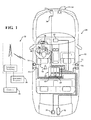
- FIG 1 schematically illustrates a vehicle 20 with an emergency response system 22.
- the emergency response system 22 generally includes a sensor system 24, a control system 26, and a communication system 28. It should be appreciated that although particular systems are separately defined, each or any of the systems may be otherwise combined or segregated via hardware and/or software of the emergency response system 22.
- the sensor system 24 may include various sensors operable to identify a condition associated with the vehicle such as a condition around the vehicle 20, within the vehicle 20, and/or a condition of the driver.
- the sensor system 24 includes a sensor array 30 directed outside of the vehicle 20 to identify a condition around the vehicle 20.
- the sensor array 30 includes a first sensor system 32 generally operable to view the surrounds of the vehicle and a second sensor system 34 generally operable to identify a rate of closure with respect to another vehicle or object.
- the first sensor system 32 provide imagery from within each of a front F, a passenger side P, a rear R and a driver side D of the vehicle 20 ( Figure 2 ) to the control system 26. It should be appreciated that although four sensors are illustrated in the disclosed non-limiting embodiment, any number of sensors will benefit herefrom.
- the field of view of each sensor in the first sensor system 32 may overlap to provide a 360 degree view of that which surrounds the vehicle 20. Examples of sensors in the first sensor system 32 include, but are not limited to, video cameras, charge coupled devices, forward looking infrared, thermal systems and/or other imaging sensors and combinations thereof.
- the second sensor system 34 provides a rate of closure, ranging, closing velocity, distance, identification and/or other non-imagery data from within each of the front F, passenger side P, rear R and driver side D of the vehicle 20 to the control system 26. It should be appreciated that although four sensors are illustrated in the disclosed non-limiting embodiment, any number of sensors will benefit herefrom.
- the field of view of each sensor of the second sensor system 34 may overlap to provide a 360 view of that which surrounds the vehicle 20. Examples of sensors in the second sensor system 34 include but are not limited to RADAR, SONAR, LIDAR and/or other distance measurement sensors and combinations thereof.
- the sensor system 24 may alternatively or additionally include a driver monitor sensor 36 directed within the vehicle 20 to monitor a condition of the driver.
- the driver monitor sensor 36 in one disclosed non-limiting embodiment may identify the driver's biometric markers that can be indicative of an emergency medical condition such as heart attack or stroke.
- Example biometric markers identifiable by the driver monitor sensor 36 include, but are not limited to, heart rate, skin temperature, eye movements, sudden bodily movements, and/or others.
- the control system 26 generally includes a control module 40 with a processor 42, a memory 44, and an interface 46.
- the control module 40 may be a portion of a central vehicle control, a stand-alone unit, or other system such as a cloud-based system.
- the processor 42 may be any type of microprocessor having desired performance characteristics.
- the memory 44 may include any type of computer readable medium that stores the data and control algorithms 48 described herein below. Other operational software for the processor 42 may also be stored in the memory 44.
- the interface 46 facilitates communication with other systems such as the sensor system 24, the communication system 28 and other on board systems. On board systems include but are not limited to, a vehicle head unit, vehicle diagnostic sensors, vehicle entertainment systems, vehicle automated control, and others.
- the communication system 28 may also include a wireless communication system that is operable to communicate with an off board system 52 (illustrated schematically).
- the off board system 52 may include, for example, a terrestrial cellular tower in communication with a switching network to provide communication with an emergency responder 56.
- An emergency responder 56 may include, for example, police, ambulance, 911 public safety access point, etc.
- the communication system 28 may also establish communication with an off board contact 58 via the off board system 52, such as a parent, guardian, caregiver, friend, relative or other contact that may be preprogrammed by a driver.
- the communication system 28 may also communicate with a personal electronic device 60 such as a tablet, smart phone, or other wearable device, e.g., a watch, eyeglasses, or other device. That is, the personal electronic device 60, in this disclosed non-limiting embodiment, is a device typically carried or worn by the driver that may have a list of contacts 58 with whom the emergency response system 22 may communicate.
- a personal electronic device 60 such as a tablet, smart phone, or other wearable device, e.g., a watch, eyeglasses, or other device. That is, the personal electronic device 60, in this disclosed non-limiting embodiment, is a device typically carried or worn by the driver that may have a list of contacts 58 with whom the emergency response system 22 may communicate.
- the communication system 28 further includes a positional system 70 that is operable to determine the location of the vehicle 20 such as a GPS device.
- the communication system 28 is operable to interface with the positional system 70 to communicate the position of the vehicle 20 to the off board system 52 as well as identify, for example, a public safety access point that is local to a present position of the vehicle 20.
- an algorithm 48A for operation of the emergency response system 22 is schematically illustrated.
- the functions of the algorithm 48A are disclosed in terms of functional block diagrams and it should be appreciated by those skilled in the art with the benefit of this disclosure that these functions may be enacted in either dedicated hardware circuitry or programmed software routines as a computer readable storage medium capable of execution as instructions in a microprocessor based electronics control embodiment such as the control system 26.
- the memory 44 is an example computer storage media having embodied thereon computer-useable instructions such as the algorithms that, when executed, performs a method 100 of automated emergency response.
- the method 100 of automated emergency response of the algorithm 48A initially utilizes the second sensor system 34 to detect the position, speed, and acceleration of other cars and external objects and report that data to the control module 40 (step 102).
- the control module 40 is then operable to determine that an external object is moving toward the vehicle 20 in a manner such that that a collision is likely (step 104). It should be appraised that "likely" as defined herein may encompass various statistical probabilities and sensitivities.
- the control module 40 initiates recoding of the images provided by the first sensor system 32 (step 106). That is, the image data from the first sensor system 32 is captured as video or periodic still photos for storage in the memory 44 or other storage device. Further, the memory 44 utilized to store the data from the first sensor system 32 may be otherwise available for other purposes. Subsequent data retrieval thereby permits viewing of the collision in progress, which may be useful for resolving liability and insurance issues, and/or in a crash circumstance/avoidance database.
- an algorithm 48B for operation of the emergency response system 22 is schematically illustrated.
- the algorithm 48B provides an automated emergency response method 200.
- the automated emergency response method 200 utilizes the driver monitor sensor 36 to identify a condition of the driver and report that data to the control module 40 (step 202).
- the control module 40 is then operable to determine data indicative of an emergency medical condition such as heart attack or stroke (step 204).
- data indicative of an emergency medical condition may be of various sensitivities in response to, for example, a previously know medical condition of driver. That is, for a driver with previous heart conditions, the determination may have a lower threshold than that associated with a driver with no known medical condition.
Landscapes
- Engineering & Computer Science (AREA)
- Physics & Mathematics (AREA)
- General Physics & Mathematics (AREA)
- Mechanical Engineering (AREA)
- Business, Economics & Management (AREA)
- Emergency Management (AREA)
- Automation & Control Theory (AREA)
- Transportation (AREA)
- Traffic Control Systems (AREA)
- Alarm Systems (AREA)
- Electric Propulsion And Braking For Vehicles (AREA)
- Time Recorders, Dirve Recorders, Access Control (AREA)
Abstract
Description
- The present disclosure relates to a vehicle, and more particularly to an emergency response system therefor.
- Vehicles often include emergency response systems in which an off board human adviser fields emergency calls that are manually initiated at the vehicle either by depressing an emergency button or are automatically initiated upon deployment of an air bag in the event of a collision. The emergency call indicates the geographic location of the vehicle, and places the adviser in voice communication with the passenger compartment. If the adviser determines that emergency attention is necessary because of occupant response, or because there was no response, the adviser may dispatch an emergency responder. Such systems thereby require interaction and reliance upon an often less than effective adviser.
- The emergency response system described herein provides for the determination that an external object is moving toward the vehicle in a manner that indicates a potential collision to initiate recoding of a view around the vehicle. Subsequent review thereby permits viewing of the collision in progress. Such imagery may be useful to resolve liability and insurance issues, and/or in a collision avoidance database. The emergency response system can also identify a condition of the driver to determine an emergency medical condition, autopilot the vehicle to the side of a road, and communicate an alert directly to an emergency responder.
- A computer storage media having embodied thereon computer-useable instructions that, when executed, perform a method, the method according to one disclosed non-limiting embodiment includes, identifying a condition with respect to the vehicle that indicates a potential collision, and recording imagery from around the vehicle in response to the identifying.
- A computer storage media having embodied thereon computer-useable instructions that, when executed, perform a method, the method according to another disclosed non-limiting embodiment includes, identifying a condition of a driver of the vehicle indicative of an emergency medical condition, and initiating an automated pullover system to autopilot the vehicle.
- A computer storage media having embodied thereon computer-useable instructions that, when executed, perform a method, the method according to another disclosed non-limiting embodiment includes, identifying a condition of a driver of the vehicle indicative of an emergency medical condition and communicating an alert to an emergency responder through a communication system in response to identification of the emergency medical condition.
- The foregoing features and elements may be combined in various combinations without exclusivity, unless expressly indicated otherwise. These features and elements as well as the operation thereof will become more apparent in light of the following description and the accompanying drawings. It should be understood, however, the following description and drawings are intended to be exemplary in nature and non-limiting.
- Various features will become apparent to those skilled in the art from the following detailed description of the disclosed non-limiting embodiments. The drawings that accompany the detailed description can be briefly described as follows:
-
Figure 1 is a schematic view of an example vehicle for use with an emergency response system; -
Figure 2 is a view provided from the emergency response system; -
Figure 3 is a flow chart illustrating operations of the emergency response system according to one disclosed non-limiting embodiment; and -
Figure 4 is a flow chart illustrating operations of the emergency response system according to another disclosed non-limiting embodiment. - An emergency response system for a vehicle is disclosed. The emergency response system provides a method that initiates recoding of images around the vehicle in response to the determination that an external object is moving toward the vehicle in a manner that may indicate a potential collision. The emergency response system includes an imaging sensor system and a distance measurement system that provides a full 360 degree view around the vehicle. Subsequent review of the imagery permits viewing of the collision in progress. The emergency response system can also include a driver monitor sensor to identify the biometric markers of the driver. The biometric markers can be utilized to indicate an emergency medical condition such as heart attack or stroke to initiate auto piloting of the vehicle, and communication of an alert to an emergency responder.
-
Figure 1 schematically illustrates avehicle 20 with anemergency response system 22. Theemergency response system 22 generally includes asensor system 24, acontrol system 26, and acommunication system 28. It should be appreciated that although particular systems are separately defined, each or any of the systems may be otherwise combined or segregated via hardware and/or software of theemergency response system 22. - The
sensor system 24 may include various sensors operable to identify a condition associated with the vehicle such as a condition around thevehicle 20, within thevehicle 20, and/or a condition of the driver. In one disclosed non-limiting embodiment, thesensor system 24 includes asensor array 30 directed outside of thevehicle 20 to identify a condition around thevehicle 20. Thesensor array 30 includes afirst sensor system 32 generally operable to view the surrounds of the vehicle and asecond sensor system 34 generally operable to identify a rate of closure with respect to another vehicle or object. - The
first sensor system 32 provide imagery from within each of a front F, a passenger side P, a rear R and a driver side D of the vehicle 20 (Figure 2 ) to thecontrol system 26. It should be appreciated that although four sensors are illustrated in the disclosed non-limiting embodiment, any number of sensors will benefit herefrom. The field of view of each sensor in thefirst sensor system 32 may overlap to provide a 360 degree view of that which surrounds thevehicle 20. Examples of sensors in thefirst sensor system 32 include, but are not limited to, video cameras, charge coupled devices, forward looking infrared, thermal systems and/or other imaging sensors and combinations thereof. - The
second sensor system 34 provides a rate of closure, ranging, closing velocity, distance, identification and/or other non-imagery data from within each of the front F, passenger side P, rear R and driver side D of thevehicle 20 to thecontrol system 26. It should be appreciated that although four sensors are illustrated in the disclosed non-limiting embodiment, any number of sensors will benefit herefrom. The field of view of each sensor of thesecond sensor system 34 may overlap to provide a 360 view of that which surrounds thevehicle 20. Examples of sensors in thesecond sensor system 34 include but are not limited to RADAR, SONAR, LIDAR and/or other distance measurement sensors and combinations thereof. - The
sensor system 24 may alternatively or additionally include adriver monitor sensor 36 directed within thevehicle 20 to monitor a condition of the driver. Thedriver monitor sensor 36 in one disclosed non-limiting embodiment may identify the driver's biometric markers that can be indicative of an emergency medical condition such as heart attack or stroke. Example biometric markers identifiable by thedriver monitor sensor 36 include, but are not limited to, heart rate, skin temperature, eye movements, sudden bodily movements, and/or others. - The
control system 26 generally includes acontrol module 40 with aprocessor 42, amemory 44, and aninterface 46. Thecontrol module 40 may be a portion of a central vehicle control, a stand-alone unit, or other system such as a cloud-based system. Theprocessor 42 may be any type of microprocessor having desired performance characteristics. Thememory 44 may include any type of computer readable medium that stores the data andcontrol algorithms 48 described herein below. Other operational software for theprocessor 42 may also be stored in thememory 44. Theinterface 46 facilitates communication with other systems such as thesensor system 24, thecommunication system 28 and other on board systems. On board systems include but are not limited to, a vehicle head unit, vehicle diagnostic sensors, vehicle entertainment systems, vehicle automated control, and others. - The
communication system 28 may also include a wireless communication system that is operable to communicate with an off board system 52 (illustrated schematically). The offboard system 52 may include, for example, a terrestrial cellular tower in communication with a switching network to provide communication with anemergency responder 56. Anemergency responder 56 may include, for example, police, ambulance, 911 public safety access point, etc. Thecommunication system 28 may also establish communication with an offboard contact 58 via the offboard system 52, such as a parent, guardian, caregiver, friend, relative or other contact that may be preprogrammed by a driver. - The
communication system 28 may also communicate with a personalelectronic device 60 such as a tablet, smart phone, or other wearable device, e.g., a watch, eyeglasses, or other device. That is, the personalelectronic device 60, in this disclosed non-limiting embodiment, is a device typically carried or worn by the driver that may have a list ofcontacts 58 with whom theemergency response system 22 may communicate. - The
communication system 28 further includes apositional system 70 that is operable to determine the location of thevehicle 20 such as a GPS device. Thecommunication system 28 is operable to interface with thepositional system 70 to communicate the position of thevehicle 20 to the offboard system 52 as well as identify, for example, a public safety access point that is local to a present position of thevehicle 20. - With reference to
Figure 3 , in one disclosed non-limiting embodiment, analgorithm 48A for operation of theemergency response system 22 is schematically illustrated. The functions of thealgorithm 48A are disclosed in terms of functional block diagrams and it should be appreciated by those skilled in the art with the benefit of this disclosure that these functions may be enacted in either dedicated hardware circuitry or programmed software routines as a computer readable storage medium capable of execution as instructions in a microprocessor based electronics control embodiment such as thecontrol system 26. That is, thememory 44 is an example computer storage media having embodied thereon computer-useable instructions such as the algorithms that, when executed, performs amethod 100 of automated emergency response. - The
method 100 of automated emergency response of thealgorithm 48A initially utilizes thesecond sensor system 34 to detect the position, speed, and acceleration of other cars and external objects and report that data to the control module 40 (step 102). Thecontrol module 40 is then operable to determine that an external object is moving toward thevehicle 20 in a manner such that that a collision is likely (step 104). It should be appraised that "likely" as defined herein may encompass various statistical probabilities and sensitivities. - In response to the determination that the external object is moving toward the
vehicle 20 in a manner such that that a collision is likely, thecontrol module 40 initiates recoding of the images provided by the first sensor system 32 (step 106). That is, the image data from thefirst sensor system 32 is captured as video or periodic still photos for storage in thememory 44 or other storage device. Further, thememory 44 utilized to store the data from thefirst sensor system 32 may be otherwise available for other purposes. Subsequent data retrieval thereby permits viewing of the collision in progress, which may be useful for resolving liability and insurance issues, and/or in a crash circumstance/avoidance database. - With reference to
Figure 4 , in another disclosed non-limiting embodiment, analgorithm 48B for operation of theemergency response system 22 is schematically illustrated. Thealgorithm 48B provides an automatedemergency response method 200. Initially, the automatedemergency response method 200 utilizes thedriver monitor sensor 36 to identify a condition of the driver and report that data to the control module 40 (step 202). Thecontrol module 40 is then operable to determine data indicative of an emergency medical condition such as heart attack or stroke (step 204). It should be appreciated that data indicative of an emergency medical condition may be of various sensitivities in response to, for example, a previously know medical condition of driver. That is, for a driver with previous heart conditions, the determination may have a lower threshold than that associated with a driver with no known medical condition. - In response to the determination of the emergency medical condition, the
control module 40 can initiate an automated pullover system 80 (Figure 1 ) that is operable with thesensor system 24 and thecontrol system 26 to control thevehicle 20. For example, the automatedemergency response method 200 is operable to activate hazard lights (step 206), selectively autopilot thevehicle 20 to the side of a road (step 208), and communicate with the emergency responder (step 210) through thecommunication system 28. - The use of the terms "a," "an," "the," and similar references in the context of description (especially in the context of the following claims) are to be construed to cover both the singular and the plural, unless otherwise indicated herein or specifically contradicted by context. The modifier "about" used in connection with a quantity is inclusive of the stated value and has the meaning dictated by the context (e.g., it includes the degree of error associated with measurement of the particular quantity). All ranges disclosed herein are inclusive of the endpoints, and the endpoints are independently combinable with each other.
- Although the different non-limiting embodiments have specific illustrated components, the embodiments of this invention are not limited to those particular combinations. It is possible to use some of the components or features from any of the non-limiting embodiments in combination with features or components from any of the other non-limiting embodiments.
- It should be appreciated that like reference numerals identify corresponding or similar elements throughout the several drawings. It should also be appreciated that although a particular component arrangement is disclosed in the illustrated embodiment, other arrangements will benefit herefrom.
- Although particular step sequences are shown, described, and claimed, it should be understood that steps may be performed in any order, separated or combined unless otherwise indicated and will still benefit from the present disclosure.
- The foregoing description is exemplary rather than defined by the limitations within. Various non-limiting embodiments are disclosed herein, however, one of ordinary skill in the art would recognize that various modifications and variations in light of the above teachings will fall within the scope of the appended claims. It is therefore to be appreciated that within the scope of the appended claims, the disclosure may be practiced other than as specifically described. For that reason the appended claims should be studied to determine true scope and content.
Claims (15)
- A computer storage media having embodied thereon computer-useable instructions that, when executed, perform a method, the method comprising:identifying a condition with respect to the vehicle that indicates a potential collision; andrecording imagery from around the vehicle in response to the identifying.
- The computer storage media as recited in claim 1, wherein the method step of recoding imagery is performed with a first sensor system.
- The computer storage media as recited in claim 2, wherein the method step of identifying the condition is performed with a second sensor system different than the first sensor system.
- The computer storage media as recited in claim 3, wherein the method step of identifying the condition includes identifying a rate of closure via at least one of RADAR, SONAR, and LIDAR.
- The computer storage media as recited in claim 1, wherein the method step of recoding imagery includes at least one of recording video, and recording a series of still images.
- A computer storage media having embodied thereon computer-useable instructions that, when executed, perform a method, the method comprising:identifying a condition of a driver of the vehicle indicative of an emergency medical condition; andinitiating an automated pullover system in response to identification of the emergency medical condition to autopilot the vehicle.
- The computer storage media as recited in claim 6, wherein the method step of identifying the condition of a driver is performed with a driver monitor sensor.
- The computer storage media as recited in claim 7, wherein the method step of identifying the condition of the driver includes identifying at least one biometric marker of the driver selected from the group consisting of a heart rate, a skin temperature, an eye movement and a sudden bodily movement.
- The computer storage media as recited in claim 6, wherein the method further comprises activating a vehicle hazard light and auto piloting the vehicle to a side of a road.
- The computer storage media as recited in claim 6, wherein the method further comprises communicating an alert to an emergency responder in response to identifying the emergency medical condition.
- A computer storage media having embodied thereon computer-useable instructions that, when executed, perform a method, the method comprising:identifying a condition of a driver of the vehicle indicative of an emergency medical condition; andcommunicating an alert to an emergency responder through a communication system in response to identification of the emergency medical condition.
- The computer storage media as recited in claim 11, wherein the method further comprises initiating an automated pullover system in response to the identification of the emergency medical condition to selectively autopilot the vehicle to a side of a road.
- The method as recited in claim 12, wherein the method further comprises activating a vehicle hazard light.
- The computer storage media as recited in claim 12, wherein the step of identifying is performed with a driver monitor sensor operable to identify at least one biometric marker of the driver.
- The computer storage media as recited in claim 14, wherein the biometric marker includes at least one of a heart rate, a skin temperature, an eye movement and a sudden bodily movement.
Applications Claiming Priority (1)
| Application Number | Priority Date | Filing Date | Title |
|---|---|---|---|
| US14/304,970 US20150360617A1 (en) | 2014-06-15 | 2014-06-15 | Automated Emergency Response Systems for a Vehicle |
Publications (2)
| Publication Number | Publication Date |
|---|---|
| EP2955700A2 true EP2955700A2 (en) | 2015-12-16 |
| EP2955700A3 EP2955700A3 (en) | 2016-05-11 |
Family
ID=53476691
Family Applications (1)
| Application Number | Title | Priority Date | Filing Date |
|---|---|---|---|
| EP15172186.7A Withdrawn EP2955700A3 (en) | 2014-06-15 | 2015-06-15 | Automated emergency response systems for a vehicle |
Country Status (3)
| Country | Link |
|---|---|
| US (1) | US20150360617A1 (en) |
| EP (1) | EP2955700A3 (en) |
| JP (1) | JP2016028318A (en) |
Cited By (4)
| Publication number | Priority date | Publication date | Assignee | Title |
|---|---|---|---|---|
| CN106920397A (en) * | 2015-12-25 | 2017-07-04 | 北京奇虎科技有限公司 | The control method and device of vehicle |
| CN109747634A (en) * | 2017-11-07 | 2019-05-14 | 福特全球技术公司 | Audio Alarm for Remote Park Assist Tethering |
| FR3104113A1 (en) * | 2019-12-09 | 2021-06-11 | Psa Automobiles Sa | Vehicle data recording method and device |
| EP3960567A1 (en) * | 2020-08-25 | 2022-03-02 | Molex CVS Bochum GmbH | Telematics control units (tcus) including sensors for monitoring vehicle interiors and method for operating a tcu |
Families Citing this family (10)
| Publication number | Priority date | Publication date | Assignee | Title |
|---|---|---|---|---|
| DE102014212758A1 (en) * | 2014-07-02 | 2016-01-07 | Robert Bosch Gmbh | Method and device for detecting a driver of a vehicle |
| KR101627741B1 (en) * | 2015-06-11 | 2016-06-07 | 양선종 | remote controlling and lifesaving apparatus using a wearable device system within a car |
| US20180012197A1 (en) * | 2016-07-07 | 2018-01-11 | NextEv USA, Inc. | Battery exchange licensing program based on state of charge of battery pack |
| JP6627684B2 (en) * | 2016-08-03 | 2020-01-08 | オムロン株式会社 | Driver status determination device, vehicle control system |
| JP6642398B2 (en) | 2016-12-06 | 2020-02-05 | トヨタ自動車株式会社 | Autonomous driving system |
| KR102287316B1 (en) | 2017-04-14 | 2021-08-09 | 현대자동차주식회사 | Apparatus and method for autonomous driving control, vehicle system |
| US10376198B1 (en) * | 2017-11-10 | 2019-08-13 | Rockwell Collins, Inc. | Pilot fatigue and attention tunneling using biometric monitoring |
| CN111683702B (en) * | 2017-12-11 | 2022-09-02 | 赛诺菲 | Device for managing medication system |
| CN111275929A (en) * | 2020-01-21 | 2020-06-12 | 东风小康汽车有限公司重庆分公司 | Vehicle overtopping early warning method, device and system |
| US20220266862A1 (en) * | 2021-02-25 | 2022-08-25 | Autonomous Solutions, Inc. | Intelligent urgent stop system for an autonomous vehicle |
Family Cites Families (10)
| Publication number | Priority date | Publication date | Assignee | Title |
|---|---|---|---|---|
| KR100658898B1 (en) * | 2000-12-29 | 2006-12-15 | 엘지전자 주식회사 | Vehicle accident notification method and device using hand-free device |
| US7076235B2 (en) * | 2002-12-03 | 2006-07-11 | Sony Ericsson Mobile Communications Ab | Automatic notification of personal emergency contacts from a wireless communications device |
| JP2005310092A (en) * | 2004-04-22 | 2005-11-04 | Hideyuki Nakajima | Cellular phone for nursing care corresponding to gps |
| KR100736721B1 (en) * | 2004-08-31 | 2007-07-09 | 재단법인서울대학교산학협력재단 | Electric non-contact apparatus and method for taking electrocardiograms |
| US8718235B2 (en) * | 2006-03-03 | 2014-05-06 | Kyocera Corporation | Mobile information terminal |
| DE102012200189A1 (en) * | 2012-01-09 | 2013-07-11 | Robert Bosch Gmbh | Method for operating a vehicle |
| KR101947493B1 (en) * | 2012-03-28 | 2019-02-14 | 삼성전자주식회사 | Image recording apparatus and method for automotive using obd information |
| RS63951B1 (en) * | 2012-04-13 | 2023-02-28 | Wi Tronix Llc | Method for recording, processing and transmitting data from a mobile asset |
| DE102013003496A1 (en) * | 2013-02-28 | 2013-08-29 | Daimler Ag | Method for documentation of collision warning generated during driving of motor car, involves recording collision warning, and evaluating stored collision warning information after the termination of travel |
| GB2514151A (en) * | 2013-05-15 | 2014-11-19 | Nissan Motor Mfg Uk Ltd | Event detection and recording methods and systems |
-
2014
- 2014-06-15 US US14/304,970 patent/US20150360617A1/en not_active Abandoned
-
2015
- 2015-06-11 JP JP2015118076A patent/JP2016028318A/en active Pending
- 2015-06-15 EP EP15172186.7A patent/EP2955700A3/en not_active Withdrawn
Non-Patent Citations (1)
| Title |
|---|
| None |
Cited By (4)
| Publication number | Priority date | Publication date | Assignee | Title |
|---|---|---|---|---|
| CN106920397A (en) * | 2015-12-25 | 2017-07-04 | 北京奇虎科技有限公司 | The control method and device of vehicle |
| CN109747634A (en) * | 2017-11-07 | 2019-05-14 | 福特全球技术公司 | Audio Alarm for Remote Park Assist Tethering |
| FR3104113A1 (en) * | 2019-12-09 | 2021-06-11 | Psa Automobiles Sa | Vehicle data recording method and device |
| EP3960567A1 (en) * | 2020-08-25 | 2022-03-02 | Molex CVS Bochum GmbH | Telematics control units (tcus) including sensors for monitoring vehicle interiors and method for operating a tcu |
Also Published As
| Publication number | Publication date |
|---|---|
| EP2955700A3 (en) | 2016-05-11 |
| US20150360617A1 (en) | 2015-12-17 |
| JP2016028318A (en) | 2016-02-25 |
Similar Documents
| Publication | Publication Date | Title |
|---|---|---|
| EP2955700A2 (en) | Automated emergency response systems for a vehicle | |
| US12159471B2 (en) | Vehicle driver monitoring system | |
| US11295143B2 (en) | Information processing apparatus, information processing method, and program | |
| EP3016815B1 (en) | Operator drowsiness detection in surface mines | |
| US9731727B2 (en) | Method and device for detecting the alertness of a vehicle driver | |
| CN113044043B (en) | Autonomous vehicle control system and autonomous vehicle control method using the same | |
| US11034294B2 (en) | Driving notification method and driving notification system | |
| US10089879B2 (en) | Boundary detection system | |
| US20210078408A1 (en) | System and method for correlating user attention direction and outside view | |
| EP3316231B1 (en) | Alert generation correlating between head mounted imaging data and external device | |
| US10796132B2 (en) | Public service system and method using autonomous smart car | |
| US10009580B2 (en) | Method for supplementing a piece of object information assigned to an object and method for selecting objects in surroundings of a vehicle | |
| US8379924B2 (en) | Real time environment model generation system | |
| US11223381B2 (en) | Phone docking station mounted on a vehicle for enhanced driving safety | |
| CN108263379A (en) | Pedestrian detection and pedestrian impact preventing mean and method based on pose information | |
| JP7234614B2 (en) | Anomaly detection device, anomaly detection system and anomaly detection program | |
| US9598012B2 (en) | Surroundings monitoring system for a vehicle | |
| US20250193649A1 (en) | Vehicular Emergency Notification | |
| KR101784096B1 (en) | Integrated terminal for vehicle | |
| CN109823344A (en) | Driving prompt method and system | |
| JP6740644B2 (en) | Notification device | |
| US20240112147A1 (en) | Systems and methods to provide services to a disabled vehicle | |
| CN108140315B (en) | Enhanced rear obstacle detection |
Legal Events
| Date | Code | Title | Description |
|---|---|---|---|
| PUAI | Public reference made under article 153(3) epc to a published international application that has entered the european phase |
Free format text: ORIGINAL CODE: 0009012 |
|
| AK | Designated contracting states |
Kind code of ref document: A2 Designated state(s): AL AT BE BG CH CY CZ DE DK EE ES FI FR GB GR HR HU IE IS IT LI LT LU LV MC MK MT NL NO PL PT RO RS SE SI SK SM TR |
|
| AX | Request for extension of the european patent |
Extension state: BA ME |
|
| RIC1 | Information provided on ipc code assigned before grant |
Ipc: G07C 5/08 20060101AFI20151214BHEP |
|
| PUAL | Search report despatched |
Free format text: ORIGINAL CODE: 0009013 |
|
| AK | Designated contracting states |
Kind code of ref document: A3 Designated state(s): AL AT BE BG CH CY CZ DE DK EE ES FI FR GB GR HR HU IE IS IT LI LT LU LV MC MK MT NL NO PL PT RO RS SE SI SK SM TR |
|
| AX | Request for extension of the european patent |
Extension state: BA ME |
|
| RIC1 | Information provided on ipc code assigned before grant |
Ipc: G07C 5/08 20060101AFI20160405BHEP |
|
| STAA | Information on the status of an ep patent application or granted ep patent |
Free format text: STATUS: THE APPLICATION HAS BEEN PUBLISHED |
|
| STAA | Information on the status of an ep patent application or granted ep patent |
Free format text: STATUS: THE APPLICATION IS DEEMED TO BE WITHDRAWN |
|
| 18D | Application deemed to be withdrawn |
Effective date: 20161112 |