EP2955555A1 - Short optical terminus - Google Patents
Short optical terminus Download PDFInfo
- Publication number
- EP2955555A1 EP2955555A1 EP15170218.0A EP15170218A EP2955555A1 EP 2955555 A1 EP2955555 A1 EP 2955555A1 EP 15170218 A EP15170218 A EP 15170218A EP 2955555 A1 EP2955555 A1 EP 2955555A1
- Authority
- EP
- European Patent Office
- Prior art keywords
- pin
- socket
- sleeve
- length
- optical connector
- Prior art date
- Legal status (The legal status is an assumption and is not a legal conclusion. Google has not performed a legal analysis and makes no representation as to the accuracy of the status listed.)
- Withdrawn
Links
- 230000003287 optical effect Effects 0.000 title claims abstract description 33
- 239000000835 fiber Substances 0.000 description 15
- 230000013011 mating Effects 0.000 description 12
- 230000008901 benefit Effects 0.000 description 5
- 230000015556 catabolic process Effects 0.000 description 4
- 230000008878 coupling Effects 0.000 description 4
- 238000010168 coupling process Methods 0.000 description 4
- 238000005859 coupling reaction Methods 0.000 description 4
- 238000006731 degradation reaction Methods 0.000 description 4
- RYGMFSIKBFXOCR-UHFFFAOYSA-N Copper Chemical compound [Cu] RYGMFSIKBFXOCR-UHFFFAOYSA-N 0.000 description 3
- 239000010949 copper Substances 0.000 description 3
- 229910052802 copper Inorganic materials 0.000 description 3
- 239000013307 optical fiber Substances 0.000 description 3
- 230000000694 effects Effects 0.000 description 2
- 230000037361 pathway Effects 0.000 description 2
- 230000000717 retained effect Effects 0.000 description 2
- 230000003466 anti-cipated effect Effects 0.000 description 1
- 230000000712 assembly Effects 0.000 description 1
- 238000000429 assembly Methods 0.000 description 1
- 230000008859 change Effects 0.000 description 1
- 239000000428 dust Substances 0.000 description 1
- 230000008030 elimination Effects 0.000 description 1
- 238000003379 elimination reaction Methods 0.000 description 1
- 230000007246 mechanism Effects 0.000 description 1
- 239000002245 particle Substances 0.000 description 1
- 230000005855 radiation Effects 0.000 description 1
- 238000000926 separation method Methods 0.000 description 1
- 230000008054 signal transmission Effects 0.000 description 1
Images


Classifications
-
- G—PHYSICS
- G02—OPTICS
- G02B—OPTICAL ELEMENTS, SYSTEMS OR APPARATUS
- G02B6/00—Light guides; Structural details of arrangements comprising light guides and other optical elements, e.g. couplings
- G02B6/24—Coupling light guides
- G02B6/36—Mechanical coupling means
- G02B6/38—Mechanical coupling means having fibre to fibre mating means
- G02B6/3807—Dismountable connectors, i.e. comprising plugs
- G02B6/3873—Connectors using guide surfaces for aligning ferrule ends, e.g. tubes, sleeves, V-grooves, rods, pins, balls
- G02B6/3874—Connectors using guide surfaces for aligning ferrule ends, e.g. tubes, sleeves, V-grooves, rods, pins, balls using tubes, sleeves to align ferrules
-
- G—PHYSICS
- G02—OPTICS
- G02B—OPTICAL ELEMENTS, SYSTEMS OR APPARATUS
- G02B6/00—Light guides; Structural details of arrangements comprising light guides and other optical elements, e.g. couplings
- G02B6/24—Coupling light guides
- G02B6/36—Mechanical coupling means
- G02B6/38—Mechanical coupling means having fibre to fibre mating means
- G02B6/3807—Dismountable connectors, i.e. comprising plugs
- G02B6/381—Dismountable connectors, i.e. comprising plugs of the ferrule type, e.g. fibre ends embedded in ferrules, connecting a pair of fibres
-
- G—PHYSICS
- G02—OPTICS
- G02B—OPTICAL ELEMENTS, SYSTEMS OR APPARATUS
- G02B6/00—Light guides; Structural details of arrangements comprising light guides and other optical elements, e.g. couplings
- G02B6/24—Coupling light guides
- G02B6/36—Mechanical coupling means
- G02B6/38—Mechanical coupling means having fibre to fibre mating means
- G02B6/3807—Dismountable connectors, i.e. comprising plugs
- G02B6/381—Dismountable connectors, i.e. comprising plugs of the ferrule type, e.g. fibre ends embedded in ferrules, connecting a pair of fibres
- G02B6/3818—Dismountable connectors, i.e. comprising plugs of the ferrule type, e.g. fibre ends embedded in ferrules, connecting a pair of fibres of a low-reflection-loss type
- G02B6/3821—Dismountable connectors, i.e. comprising plugs of the ferrule type, e.g. fibre ends embedded in ferrules, connecting a pair of fibres of a low-reflection-loss type with axial spring biasing or loading means
-
- G—PHYSICS
- G02—OPTICS
- G02B—OPTICAL ELEMENTS, SYSTEMS OR APPARATUS
- G02B6/00—Light guides; Structural details of arrangements comprising light guides and other optical elements, e.g. couplings
- G02B6/24—Coupling light guides
- G02B6/36—Mechanical coupling means
- G02B6/38—Mechanical coupling means having fibre to fibre mating means
- G02B6/3807—Dismountable connectors, i.e. comprising plugs
- G02B6/3833—Details of mounting fibres in ferrules; Assembly methods; Manufacture
- G02B6/3853—Lens inside the ferrule
-
- G—PHYSICS
- G02—OPTICS
- G02B—OPTICAL ELEMENTS, SYSTEMS OR APPARATUS
- G02B6/00—Light guides; Structural details of arrangements comprising light guides and other optical elements, e.g. couplings
- G02B6/24—Coupling light guides
- G02B6/36—Mechanical coupling means
- G02B6/38—Mechanical coupling means having fibre to fibre mating means
- G02B6/3807—Dismountable connectors, i.e. comprising plugs
- G02B6/3869—Mounting ferrules to connector body, i.e. plugs
-
- G—PHYSICS
- G02—OPTICS
- G02B—OPTICAL ELEMENTS, SYSTEMS OR APPARATUS
- G02B6/00—Light guides; Structural details of arrangements comprising light guides and other optical elements, e.g. couplings
- G02B6/24—Coupling light guides
- G02B6/36—Mechanical coupling means
- G02B6/38—Mechanical coupling means having fibre to fibre mating means
- G02B6/3807—Dismountable connectors, i.e. comprising plugs
- G02B6/3873—Connectors using guide surfaces for aligning ferrule ends, e.g. tubes, sleeves, V-grooves, rods, pins, balls
- G02B6/3874—Connectors using guide surfaces for aligning ferrule ends, e.g. tubes, sleeves, V-grooves, rods, pins, balls using tubes, sleeves to align ferrules
- G02B6/3878—Connectors using guide surfaces for aligning ferrule ends, e.g. tubes, sleeves, V-grooves, rods, pins, balls using tubes, sleeves to align ferrules comprising a plurality of ferrules, branching and break-out means
-
- G—PHYSICS
- G02—OPTICS
- G02B—OPTICAL ELEMENTS, SYSTEMS OR APPARATUS
- G02B6/00—Light guides; Structural details of arrangements comprising light guides and other optical elements, e.g. couplings
- G02B6/24—Coupling light guides
- G02B6/36—Mechanical coupling means
- G02B6/38—Mechanical coupling means having fibre to fibre mating means
- G02B6/3807—Dismountable connectors, i.e. comprising plugs
- G02B6/389—Dismountable connectors, i.e. comprising plugs characterised by the method of fastening connecting plugs and sockets, e.g. screw- or nut-lock, snap-in, bayonet type
- G02B6/3893—Push-pull type, e.g. snap-in, push-on
-
- G—PHYSICS
- G02—OPTICS
- G02B—OPTICAL ELEMENTS, SYSTEMS OR APPARATUS
- G02B6/00—Light guides; Structural details of arrangements comprising light guides and other optical elements, e.g. couplings
- G02B6/24—Coupling light guides
- G02B6/26—Optical coupling means
- G02B6/32—Optical coupling means having lens focusing means positioned between opposed fibre ends
-
- G—PHYSICS
- G02—OPTICS
- G02B—OPTICAL ELEMENTS, SYSTEMS OR APPARATUS
- G02B6/00—Light guides; Structural details of arrangements comprising light guides and other optical elements, e.g. couplings
- G02B6/24—Coupling light guides
- G02B6/36—Mechanical coupling means
- G02B6/38—Mechanical coupling means having fibre to fibre mating means
- G02B6/3807—Dismountable connectors, i.e. comprising plugs
- G02B6/381—Dismountable connectors, i.e. comprising plugs of the ferrule type, e.g. fibre ends embedded in ferrules, connecting a pair of fibres
- G02B6/3817—Dismountable connectors, i.e. comprising plugs of the ferrule type, e.g. fibre ends embedded in ferrules, connecting a pair of fibres containing optical and electrical conductors
Definitions
- the present invention relates generally to ruggedized optical termini, and, more specifically, to termini applicable to ruggedized optical connectors having a shortened length.
- Optical fiber connectors are a critical part of essentially all optical fiber communication systems. For instance, such connectors are used to join segments of fiber into longer lengths, to connect fiber to active devices, such as radiation sources, detectors and repeaters, and to connect fiber to passive devices, such as switches, multiplexers, and attenuators.
- the principal function of an optical fiber connector is to hold the fiber end such that the fiber's core is axially aligned with an optical pathway of the mating structure. This way, light from the fiber is optically coupled to the optical pathway.
- multi-cavity connectors typically comprise an outer housing defining a plurality of cavities for holding inner assemblies or “inserts," or, more specifically pin inserts and socket inserts for receiving pin or socket termini (see, e.g., US Patent Nos. 7,775,725 , and 8,827,567 ).
- multi-cavity connectors have evolved into a ruggedized connector system, comprising an outer housing, which is configured to mate with the outer housing of a mating connector, typically through a screw connection.
- Numerous United States Military specifications describe such multi-cavity connectors and fiber optic terminals, including, for example, MIL-C-38999, MIL-C-5015 and ARINC600 among others.
- the current TE size 16 expanded beam (EB) termini are designed with a similar dimensional envelope as that of the well-known fiber optic physical contacts: MIL-29504/4D/5D. This means that the size 16 expanded beam design will fit into the same cavity and can be inserted and removed with the same tools.
- the spring-loaded size 16 socket terminus is too long and does not fit into the connector half.
- the problem to be solved is a need for a terminus that is shorter than traditional optical terminus and can be used in existing shorter connectors, such as the European EN4165 and EN4644 connectors.
- an optical connector comprising: (a) a plug housing having a pin cavity; (b) a pin having a front and rear orientation and disposed at least partially in said pin cavity, the pin comprising at least a pin sleeve having a pin sleeve length, the pin sleeve at least partially containing a pin ferrule and a pin lens; (c) a receptacle housing having a socket cavity; (d) a socket having a front and rear orientation and disposed at least partially in the socket cavity, the socket comprising at least a socket sleeve having a socket sleeve length, the socket sleeve at least partially containing a socket ferrule and a socket lens; (e) an alignment sleeve between the pin and socket, wherein a pin front portion of the pin sleeve and a socket front portion of the socket sleeve are disposed in the alignment sleeve, wherein the pin front portion and the socket portion are
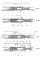
- the connector system 500 comprises a plug housing 102 having a pin cavity 102a (see Fig. 1 ). At least partially disposed in the cavity 102a is a pin 501 (see Fig. 5a and 5b ) having a front and rear.
- the pin 501 comprises at least a pin sleeve 502 having a pin sleeve length (PSL).
- the pin sleeve 502 at least partially contains a pin ferrule 503 and a pin lens 504.
- the connector system 500 also comprises a receptacle housing 103, having a socket cavity 103a (as shown in Fig. 1 ).
- the socket 511 comprises at least a socket sleeve 512 having a socket sleeve length (SSL).
- the socket sleeve at least partially contains a socket ferrule 513 and a socket lens 514.
- An alignment sleeve 520 is positioned between the pin and socket and retained within the socket shroud 523, wherein a pin front portion 521 of the pin sleeve and a socket front portion 522 of the socket sleeve are disposed in the alignment sleeve 520.
- the pin front portion and the socket portion or socket front portion are at least 1/3 the length of the pin sleeve and socket sleeve, respectively.
- a retaining mechanism e.g., a shoulder 524 - is defined at the end of the shroud to retain the sleeve 520.
- One aspect of the present invention is the recognition that a shortened terminus connector can be realized if (1) the spring that biases the terminus in the housing is eliminated, (2) the optical coupling is effected through an expanded beam, and (3) the optical coupling is near the midpoint of the alignment sleeve. More specifically, the spring occupies significant space relatively speaking, and its removal enables the length of the socket terminus to be reduced significantly. However, the spring is typically required to ensure physical contact.
- the optical socket terminus conforming to the MIL-29504/5D standard provides physical contact (PC) between the fibers of the mated pin and socket. These termini are typically used in a 38999 series III style connector and have been around for over 20 years. An expanded beam connector, however, avoids the need for PC.
- This design has significant advantages. For example, due to the non-contact design, no noticeable degradation occurs at the EB optical interfaces. This means that while the PC version will begin its performance degradation from essentially the time it has been polished and left the factory, the non-contact EB design does not experience any optical signal degradation during its lifetime. Furthermore, due to the beam expansion, the presence of dust particles in the EB environment has a much lesser effect on performance than it has for the PC environment with the result that the EB design is increasingly becoming the preferred optical terminus to use in harsh environments.
- the beam 201 is collimated, it is tolerant of axial variations between the connectors compared to PC termini, and, thus, obviates the need for a spring to register the termini to ensure precise axial positioning between termini.
- the spring used in the MIL-29504/4D/5D and in the current size 16 EB design is needed to compensate for the large tolerance of the "clip-to-clip" distance of the mated connector.
- the clips (or retainers) are positioned in the plug half and in the receptacle half of the connectors. Their purpose is to retain the rear mounted termini in their respective connector halves.
- Yet another advantage of the connector of the present invention is its low mating force requirements. Specifically, because the connector has no spring, no additional is required to compress the spring during mating, as is typically required for the spring loaded 29504 version, for example, or mating torque for circular connectors. This is particularly important for higher termini count in a given connector which can otherwise require significant force to compress the multitude of springs used in such connectors.
- a MIL-DTL-38999, series III, connector with mated size 16 expanded beam termini is shown.
- the pin 104 is mounted in the Plug connector half 102, and the spring-loaded socket 105 in disposed in the Receptacle connector half 103.
- the distance between the tips 101a of the tines 101 on two mated connector halves 102, 103, is referred to the Clip-to-Clip (CTC) distance, see Fig. 1 .
- CTC Clip-to-Clip
- the CTC distance is listed in the dimensional specification. It has a rather large tolerance in that there is a difference between the minimum and maximum CTC of about 1.32 mm.
- an EB coupling facilitates the elimination of the spring by providing the connector with the necessary axial tolerance to compensate for the tolerance in the CTC distance.
- the EB coupling also synergistically improves performance because the non-contact EB design does not experience any optical signal degradation during its lifetime.
- FIG. 3 A springless design for the size 16 EB MIL-29504 terminus 301 is shown in Fig. 3 .
- FIG. 4a and 4b A problem with this design is illustrated in Fig. 4a and 4b .
- the closest distance between the pin tip 401 and the socket tip 402 it is necessary to design the closest distance between the pin tip 401 and the socket tip 402 to occur at the minimum standardized clip-to-clip distance of 19.20 mm as shown on Fig. 4a .
- the "wipe distance" or the distance that the pin 403 reaches within the alignment sleeve 404 is approximately 2.4 mm. This also equates to the wipe distance of the regular MIL-29504/4D/5D configuration.
- the wipe distance is now reduced to approximately 1.0 mm as demonstrated in Fig. 4b .
- Such a short wipe distance is insufficient to provide proper support and alignment during a harsh environment exposure.
- the design for the springless socket of the present invention includes redesigned components and a shift back of the internal components in the socket terminus such that the mating interface between the pin and socket is positioned more towards the center of the mating or alignment sleeve. This increases the wipe distance of the pin during mating and provides sufficient structural support during exposure to a harsh mechanical environment. For example, in the embodiment of Figs. 5a and 5b , the wipe distance is increased by nearly 300% at the maximum CTC distance (worst case).
- the wipe distance of the pin ranges from about at least 1/3 to over 1/2 of the pin sleeve length. In one particular embodiment, the pin front portion is at least 40% of the pin sleeve length. In one embodiment, the pin and the socket are held in the plug and receptacle within a certain tolerance such that the relative distance between them ranges from a minimum distance to a maximum distance (e.g., a minimum and maximum CTC distance). In one embodiment, at the maximum distance, the pin front portion is at least 1/3 of the pin sleeve length. More particularly, in one embodiment, the pin front portion ranges from about at least 1/3 of the pin sleeve length at the maximum distance to over 1/2 of the pin sleeve length at the minimum distance.
- Fig. 6 shows one embodiment of the shortened, springless socket 511.
- Fig 7 compares this socket 511, which fits into an EN4165, series 2 and EN4644 connectors, to a size 16 EB MIL-29504/4D/5D socket 701 which has a spring 702. The difference in length is significant.
- the length of the socket 511 is about the same as the pin 801 as shown in Fig. 8 .
- the socket has a length of no greater than about 3 times the socket sleeve length. More particularly, in one embodiment, the socket has a length of no greater than about 2.5 times the socket sleeve length.
- Fig. 8 a size 16 expanded beam pin terminus 801 is shown, which is used for all the connector types illustrated herein.
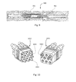
- Fig. 9 shows a cross-section of a mated pair of the EN4165, series 2 connector 900, comprising the short, springless socket 901 and the pin 902.
- Fig 10 shows the plug housing 1012 and receptacle housing 1011 of an EN4165, series 2 connector with a hybrid configuration of copper contacts 1003 and fiber pin and socket termini 1001, 1002, respectively.
- the insert configuration of the present claimed invention provides significant advantages over conventional insert configurations such as high channel density and interchangeability with existing connector components. Still other advantages of the insert and ferrule of the present invention are anticipated.
Landscapes
- Physics & Mathematics (AREA)
- General Physics & Mathematics (AREA)
- Optics & Photonics (AREA)
- Mechanical Coupling Of Light Guides (AREA)
Abstract
An optical connector comprises a plug housing having a pin cavity, and a receptacle housing having a socket cavity. A pin (501) having a front and rear orientation is disposed at least partially in the pin cavity. The pin (501) comprises at least a pin sleeve (502) which has a pin sleeve length, and the pin sleeve (502) at least partially contains a pin ferrule (503) and a pin lens (504). A socket (511) having a front and rear orientation is disposed at least partially in the socket cavity. The socket (511) comprises at least a socket sleeve (512) which has a socket sleeve length, and the socket sleeve (512) at least partially contains a socket ferrule (513) and a socket lens (514). An alignment sleeve is between the pin (501) and socket (511), wherein, when in a mated state, a pin front portion of the pin sleeve (502) and a socket front portion of the socket sleeve (512) are disposed in the alignment sleeve, the pin front portion and the socket front portion are at least one third the length of the pin sleeve (502) and socket sleeve (512), respectively.
Description
- The present invention relates generally to ruggedized optical termini, and, more specifically, to termini applicable to ruggedized optical connectors having a shortened length.
- Optical fiber connectors are a critical part of essentially all optical fiber communication systems. For instance, such connectors are used to join segments of fiber into longer lengths, to connect fiber to active devices, such as radiation sources, detectors and repeaters, and to connect fiber to passive devices, such as switches, multiplexers, and attenuators. The principal function of an optical fiber connector is to hold the fiber end such that the fiber's core is axially aligned with an optical pathway of the mating structure. This way, light from the fiber is optically coupled to the optical pathway.
- Of particular interest herein, are multi-cavity connectors. Such connectors typically comprise an outer housing defining a plurality of cavities for holding inner assemblies or "inserts," or, more specifically pin inserts and socket inserts for receiving pin or socket termini (see, e.g.,
US Patent Nos. 7,775,725 , and8,827,567 ). Over the years, multi-cavity connectors have evolved into a ruggedized connector system, comprising an outer housing, which is configured to mate with the outer housing of a mating connector, typically through a screw connection. Numerous United States Military specifications describe such multi-cavity connectors and fiber optic terminals, including, for example, MIL-C-38999, MIL-C-5015 and ARINC600 among others. - Many of these multi-cavity connectors use the same or similar sized termini. For example, the current TE size 16 expanded beam (EB) termini are designed with a similar dimensional envelope as that of the well-known fiber optic physical contacts: MIL-29504/4D/5D. This means that the size 16 expanded beam design will fit into the same cavity and can be inserted and removed with the same tools. However, for shorter connectors, such as the European modular rectangular EN4644 connector and the EN4165, which is commonly used for seat-to-seat electrical signal connections in commercial aircraft, the spring-loaded size 16 socket terminus is too long and does not fit into the connector half.
- The problem to be solved is a need for a terminus that is shorter than traditional optical terminus and can be used in existing shorter connectors, such as the European EN4165 and EN4644 connectors.
- The solution is provided by an optical connector comprising: (a) a plug housing having a pin cavity; (b) a pin having a front and rear orientation and disposed at least partially in said pin cavity, the pin comprising at least a pin sleeve having a pin sleeve length, the pin sleeve at least partially containing a pin ferrule and a pin lens; (c) a receptacle housing having a socket cavity; (d) a socket having a front and rear orientation and disposed at least partially in the socket cavity, the socket comprising at least a socket sleeve having a socket sleeve length, the socket sleeve at least partially containing a socket ferrule and a socket lens; (e) an alignment sleeve between the pin and socket, wherein a pin front portion of the pin sleeve and a socket front portion of the socket sleeve are disposed in the alignment sleeve, wherein the pin front portion and the socket portion are at least 1/3 the length of the pin sleeve and socket sleeve, respectively. In one embodiment, the socket does not have a spring to bias it in the housing and is about the same size as the pin. In an embodiment, neither the pin nor the socket comprises a spring to urge the ferrule assembly or an assembly comprising the ferrule forward.
- The invention will now be described by way of example with reference to the accompanying drawings in which:
-
Fig. 1 illustrates the Clip-to-Clip (CTC) distance (per the MIL-C-38999 standard) between the tips of the tines on two mated connector halves; -
Fig. 2 shows schematically the concept of beam expansion; -
Fig. 3 shows an approach of a design for the size 16 EB socket in a MIL-29504 type connector without a spring; -
Figs. 4a and 4b illustrate the problem with the connector springless termini in a MIL-29504 configuration incorporating the socket design ofFig. 3 ; -
Fig. 5a and 5b shows one embodiment of the connector of the present invention with a shortened socket and increased wipe distance at the minimum and maximum CTC distances, respectively; -
Fig. 6 shows the short, springless socket terminus position about midway in the alignment sleeve to provide the pin terminus with improved wipe distance; -
Fig. 7 shows a comparison between the size 16 EB MIL-29504/4D/5D socket spring version and the short, springless socket ofFig. 6 that fits into an EN4165 connector; -
Fig 8 shows a size 16 expanded beam pin terminus; -
Fig. 9 shows a cross-section of a mated pair of the EN4165 connector with the short, springless socket ofFig. 6 and the pin ofFig. 8 ; and -
Fig. 10 shows the plug and receptacle of the EN4165 with a hybrid configuration of copper and fiber optic contacts and termini. - Referring to
Figs. 5a and 5b , one embodiment of theconnector system 500 of the present invention is shown. Theconnector system 500 comprises aplug housing 102 having apin cavity 102a (seeFig. 1 ). At least partially disposed in thecavity 102a is a pin 501 (seeFig. 5a and 5b ) having a front and rear. Thepin 501 comprises at least apin sleeve 502 having a pin sleeve length (PSL). Thepin sleeve 502 at least partially contains apin ferrule 503 and apin lens 504. In one embodiment, theconnector system 500 also comprises areceptacle housing 103, having asocket cavity 103a (as shown inFig. 1 ). At least partially deposed in thesocket cavity 103 is asocket 511 having a front and rear orientation. Thesocket 511 comprises at least asocket sleeve 512 having a socket sleeve length (SSL). The socket sleeve at least partially contains asocket ferrule 513 and asocket lens 514. Analignment sleeve 520 is positioned between the pin and socket and retained within thesocket shroud 523, wherein apin front portion 521 of the pin sleeve and asocket front portion 522 of the socket sleeve are disposed in thealignment sleeve 520. In one embodiment, the pin front portion and the socket portion or socket front portion are at least 1/3 the length of the pin sleeve and socket sleeve, respectively. - In the MIL-29504/4D/5D standard configuration and the commercially-available product, the
alignment sleeve 520 is mounted over the socket ferrule, but is not retained by the shroud. Consequently, sometimes the mating sleeve stays on the pin side at connector separation. This is problematic as the sleeve is easily broken when attempting to remove it from the pin and place it back onto the socket ferrule. In one embodiment of the termini of the present invention, a retaining mechanism - e.g., a shoulder 524 - is defined at the end of the shroud to retain thesleeve 520. - One aspect of the present invention is the recognition that a shortened terminus connector can be realized if (1) the spring that biases the terminus in the housing is eliminated, (2) the optical coupling is effected through an expanded beam, and (3) the optical coupling is near the midpoint of the alignment sleeve. More specifically, the spring occupies significant space relatively speaking, and its removal enables the length of the socket terminus to be reduced significantly. However, the spring is typically required to ensure physical contact. For example, the optical socket terminus conforming to the MIL-29504/5D standard provides physical contact (PC) between the fibers of the mated pin and socket. These termini are typically used in a 38999 series III style connector and have been around for over 20 years. An expanded beam connector, however, avoids the need for PC. The design for individual expanded beam termini is described for example in
issued US Patent No. 7,775,725 andUS Patent No. 8,827,567 . The concept of beam expansion is illustrated inFig. 2 . This design takes advantage of non-contacting optics 202 (e.g., ball lenses) at theinterface 203 of twoconnectors interface 203. - This design has significant advantages. For example, due to the non-contact design, no noticeable degradation occurs at the EB optical interfaces. This means that while the PC version will begin its performance degradation from essentially the time it has been polished and left the factory, the non-contact EB design does not experience any optical signal degradation during its lifetime. Furthermore, due to the beam expansion, the presence of dust particles in the EB environment has a much lesser effect on performance than it has for the PC environment with the result that the EB design is increasingly becoming the preferred optical terminus to use in harsh environments.
- Additionally, because the
beam 201 is collimated, it is tolerant of axial variations between the connectors compared to PC termini, and, thus, obviates the need for a spring to register the termini to ensure precise axial positioning between termini. Conversely, the spring used in the MIL-29504/4D/5D and in the current size 16 EB design is needed to compensate for the large tolerance of the "clip-to-clip" distance of the mated connector. The clips (or retainers) are positioned in the plug half and in the receptacle half of the connectors. Their purpose is to retain the rear mounted termini in their respective connector halves. Once a terminus is being pushed into the cavity it will pass through the retainer and spread out its tines to the point when a terminus shoulder has passed the tines they will resiliently snap back in behind the shoulder and create a support that prevents the terminus from backing out. - Yet another advantage of the connector of the present invention is its low mating force requirements. Specifically, because the connector has no spring, no additional is required to compress the spring during mating, as is typically required for the spring loaded 29504 version, for example, or mating torque for circular connectors. This is particularly important for higher termini count in a given connector which can otherwise require significant force to compress the multitude of springs used in such connectors.
- Referring to
Fig. 1 , a MIL-DTL-38999, series III, connector with mated size 16 expanded beam termini is shown. Thepin 104 is mounted in thePlug connector half 102, and the spring-loadedsocket 105 in disposed in theReceptacle connector half 103. The distance between thetips 101a of thetines 101 on two mated connector halves 102, 103, is referred to the Clip-to-Clip (CTC) distance, seeFig. 1 . For the MIL-STD-38999, style III standard the CTC distance is listed in the dimensional specification. It has a rather large tolerance in that there is a difference between the minimum and maximum CTC of about 1.32 mm. This large tolerance is not an issue for the copper contacts for which the connector originally was designed, but is a very large distance for a pair of fiber optic termini, which typically require close proximity, if not contact, between the fibers. Thus, for the MIL-29504/4D/5D a spring was incorporated to compensate for this large CTC distance. Furthermore, the PC connection must have physical contact between the fibers at all times in order to sustain good optical signal transmission. A spring provides the resiliency necessary to force a physical fiber contact during every connector mating. Thus, the spring version of the socket is preloaded and the amount of added spring force applied during mating, created by the contact and forward travel by the pin terminus, depends on where the CTC falls within the maximum and minimum distance allowance. - On the other hand, when an expanded beam design is used, the spring force becomes somewhat irrelevant. Due to the parallel beam configuration created by the beam collimation between the emitting and receiving lenses, the distance between them theoretically has only a very small effect under perfect conditions. However, a beam is rarely perfectly collimated and a small loss change will be introduced over larger lens distances due to the diffraction angle of the collimated beam. In some cases a spring may be helpful in an EB connection during exposure to strong vibration. But generally, as indicated above, the EB performance for a well-executed design, will perform equally well with or without a resilient mating force.
- Thus, the use of an EB coupling facilitates the elimination of the spring by providing the connector with the necessary axial tolerance to compensate for the tolerance in the CTC distance. The EB coupling also synergistically improves performance because the non-contact EB design does not experience any optical signal degradation during its lifetime.
- A springless design for the size 16 EB MIL-29504
terminus 301 is shown inFig. 3 . A problem with this design is illustrated inFig. 4a and 4b . For a springless version, it is necessary to design the closest distance between thepin tip 401 and thesocket tip 402 to occur at the minimum standardized clip-to-clip distance of 19.20 mm as shown onFig. 4a . In this configuration, the "wipe distance" or the distance that thepin 403 reaches within thealignment sleeve 404 is approximately 2.4 mm. This also equates to the wipe distance of the regular MIL-29504/4D/5D configuration. However, if the connector has the maximum allowed clip-to-clip distance as permitted by the Military standards, the wipe distance is now reduced to approximately 1.0 mm as demonstrated inFig. 4b . Such a short wipe distance is insufficient to provide proper support and alignment during a harsh environment exposure. - The design for the springless socket of the present invention includes redesigned components and a shift back of the internal components in the socket terminus such that the mating interface between the pin and socket is positioned more towards the center of the mating or alignment sleeve. This increases the wipe distance of the pin during mating and provides sufficient structural support during exposure to a harsh mechanical environment. For example, in the embodiment of
Figs. 5a and 5b , the wipe distance is increased by nearly 300% at the maximum CTC distance (worst case). - In one embodiment, the wipe distance of the pin, or, in other terms, the pin front portion, ranges from about at least 1/3 to over 1/2 of the pin sleeve length. In one particular embodiment, the pin front portion is at least 40% of the pin sleeve length. In one embodiment, the pin and the socket are held in the plug and receptacle within a certain tolerance such that the relative distance between them ranges from a minimum distance to a maximum distance (e.g., a minimum and maximum CTC distance). In one embodiment, at the maximum distance, the pin front portion is at least 1/3 of the pin sleeve length. More particularly, in one embodiment, the pin front portion ranges from about at least 1/3 of the pin sleeve length at the maximum distance to over 1/2 of the pin sleeve length at the minimum distance.
-
Fig. 6 shows one embodiment of the shortened,springless socket 511.Fig 7 compares thissocket 511, which fits into an EN4165, series 2 and EN4644 connectors, to a size 16 EB MIL-29504/4D/5D socket 701 which has aspring 702. The difference in length is significant. In one embodiment, the length of thesocket 511 is about the same as thepin 801 as shown inFig. 8 . In one embodiment, the socket has a length of no greater than about 3 times the socket sleeve length. More particularly, in one embodiment, the socket has a length of no greater than about 2.5 times the socket sleeve length. - The shortened socket terminus and pin configuration of the present invention is suitable for implementation in a variety of different connector configurations. For example, referring to
Fig 8 , a size 16 expandedbeam pin terminus 801 is shown, which is used for all the connector types illustrated herein.Fig. 9 shows a cross-section of a mated pair of the EN4165, series 2connector 900, comprising the short,springless socket 901 and thepin 902.Fig 10 shows theplug housing 1012 andreceptacle housing 1011 of an EN4165, series 2 connector with a hybrid configuration ofcopper contacts 1003 and fiber pin andsocket termini - It should be apparent from the above description that the insert configuration of the present claimed invention provides significant advantages over conventional insert configurations such as high channel density and interchangeability with existing connector components. Still other advantages of the insert and ferrule of the present invention are anticipated.
Claims (17)
- An optical connector comprising:a plug housing (102) having a pin cavity (102a);a pin (501) having a front and rear orientation and disposed at least partially in said pin cavity (102a), said pin (501) comprising at least a pin sleeve (502) having a pin sleeve length (PSL), said pin sleeve (502) at least partially containing a pin ferrule (503) and a pin lens (504);a receptacle housing (103) having a socket cavity (103a);a socket (511) having a front and rear orientation and disposed at least partially in said socket cavity (103a), said socket (511) comprising at least a socket sleeve (512) having a socket sleeve length (SSL), said socket sleeve (512) at least partially containing a socket ferrule (513) and a socket lens (514); andan alignment sleeve (520) between said pin (501) and socket (511), wherein, when in a mated state, a pin front portion (521) of said pin sleeve (502) and a socket front portion (522) of said socket sleeve (512) are disposed in said alignment sleeve (520), wherein said pin front portion (521) and said socket front portion (522) are at least 1/3 the length of said pin sleeve (502) and socket sleeve (512), respectively.
- The optical connector of claim 1, wherein neither said pin (501) nor said socket (511) comprises a spring to urge an assembly comprising said ferrule (503/513) forward.
- The optical connector of claim 1 or 2, wherein said socket (511) has a length of no greater than about 3 times the socket sleeve length (SSL).
- The optical connector of claim 3, wherein said socket (511) has a length of no greater than about 2.5 times the socket sleeve length (SSL).
- The optical connector of any preceding claim, wherein said socket (511) has a length of no greater than about the length of said pin (501).
- The optical connector of any preceding claim, wherein said pin front portion (521) ranges from about at least 1/3 to over 1/2 of said pin sleeve length (PSL).
- The optical connector of claim 6, wherein said pin front portion (521) is at least 40% of said pin sleeve length (PSL).
- The optical connector of any preceding claim, wherein said alignment sleeve (520) is connected to said socket (511).
- The optical connector of any preceding claim, further comprising a shroud (523) to at least partially contain said alignment sleeve (520), wherein said shroud (523) has at least one end comprising a shoulder (524) to retain said alignment sleeve (520).
- The optical connector of any preceding claim, wherein said pin (501) and said socket (511) are held in said plug housing (102) and receptacle housing (103) within a certain tolerance such that the relative distance between the pin (501) and socket (511) ranges from a minimum distance to a maximum distance when in said mated state.
- The optical connector of claim 10, wherein at said maximum distance said pin front portion (521) is at least 1/3 of said pin sleeve length (PSL).
- The optical connector of claim 11, wherein said pin front portion ranges (521) from about at least 1/3 of said pin sleeve length (PSL) at said maximum distance to over 1/2 of said pin sleeve length (PSL) at said minimum distance.
- The optical connector of any one of claims 1 to 9, further comprising:a first clip (101) disposed between said plug housing (102) and said pin (501) in said pin cavity (102a) to position said pin (501) axially in said plug housing (102);a second clip (101) disposed between said receptacle housing (103) and said socket (511) in said socket cavity (103a) to position said socket (511) axially in said receptacle housing (103); andwherein the clip-to-clip (CTC) distance between said first and second clips (101) has a certain tolerance such that the CTC ranges from a minimum distance to a maximum distance.
- The optical connector of claim 13, wherein said pin front portion (521) ranges from about at least 1/3 of said pin sleeve length (PSL) at said maximum distance to over 1/2 of said pin sleeve length (PSL) at said minimum distance.
- The optical connector of any preceding claim, wherein said connector is a size 16 connector.
- The optical connector of claim 15, wherein said connector is a EN4165 or a EN4644.
- The optical connector of any one of claims 1 to 15, wherein said connector is a MIL-29504-type connector.
Applications Claiming Priority (2)
| Application Number | Priority Date | Filing Date | Title |
|---|---|---|---|
| US201462010218P | 2014-06-10 | 2014-06-10 | |
| US14/573,520 US9465171B2 (en) | 2014-06-10 | 2014-12-17 | Short optical terminus |
Publications (1)
| Publication Number | Publication Date |
|---|---|
| EP2955555A1 true EP2955555A1 (en) | 2015-12-16 |
Family
ID=53269403
Family Applications (1)
| Application Number | Title | Priority Date | Filing Date |
|---|---|---|---|
| EP15170218.0A Withdrawn EP2955555A1 (en) | 2014-06-10 | 2015-06-02 | Short optical terminus |
Country Status (5)
| Country | Link |
|---|---|
| US (1) | US9465171B2 (en) |
| EP (1) | EP2955555A1 (en) |
| CN (1) | CN105182478B (en) |
| BR (1) | BR102015012769A2 (en) |
| CA (1) | CA2893711A1 (en) |
Cited By (2)
| Publication number | Priority date | Publication date | Assignee | Title |
|---|---|---|---|---|
| EP3370097B1 (en) * | 2017-03-03 | 2021-02-24 | TE Connectivity Corporation | Connector with lateral and angular tolerance |
| CN114730048A (en) * | 2019-09-05 | 2022-07-08 | 北科电子科技公司 | Apparatus and system for optical connector |
Families Citing this family (6)
| Publication number | Priority date | Publication date | Assignee | Title |
|---|---|---|---|---|
| US9465171B2 (en) * | 2014-06-10 | 2016-10-11 | Tyco Electronics Corporation | Short optical terminus |
| CN107728259A (en) * | 2016-08-10 | 2018-02-23 | 泰科电子(上海)有限公司 | Connector |
| US10234635B1 (en) * | 2018-01-22 | 2019-03-19 | Te Connectivity Corporation | Modular insert assembly |
| JP2021063884A (en) * | 2019-10-11 | 2021-04-22 | ヒロセ電機株式会社 | Optical fiber insertion unit and method for building optical fiber insertion unit |
| US12013584B2 (en) * | 2021-12-02 | 2024-06-18 | Te Connectivity Solutions Gmbh | High-speed active contact |
| US12152958B2 (en) | 2022-11-11 | 2024-11-26 | Te Connectivity Solutions Gmbh | Test probe for expanded beam connector |
Citations (3)
| Publication number | Priority date | Publication date | Assignee | Title |
|---|---|---|---|---|
| US20100027943A1 (en) * | 2008-07-29 | 2010-02-04 | Deniz K Armani | Expanded beam fiber optic connection system |
| US7775725B2 (en) | 2008-10-29 | 2010-08-17 | Tyco Electronics Corporation | Single-channel expanded beam connector |
| US20130039622A1 (en) * | 2011-08-10 | 2013-02-14 | Tyco Electronics Corporation | Field-installable expanded beam connector system |
Family Cites Families (3)
| Publication number | Priority date | Publication date | Assignee | Title |
|---|---|---|---|---|
| US7218811B2 (en) * | 2002-01-10 | 2007-05-15 | The Furukawa Electric Co., Ltd. | Optical module, and multi-core optical collimator and lens housing therefor |
| US9195008B2 (en) * | 2013-02-26 | 2015-11-24 | Winchester Electronics Corporation | Expanded beam optical connector and method of making the same |
| US9465171B2 (en) * | 2014-06-10 | 2016-10-11 | Tyco Electronics Corporation | Short optical terminus |
-
2014
- 2014-12-17 US US14/573,520 patent/US9465171B2/en active Active
-
2015
- 2015-06-01 BR BR102015012769A patent/BR102015012769A2/en not_active Application Discontinuation
- 2015-06-02 EP EP15170218.0A patent/EP2955555A1/en not_active Withdrawn
- 2015-06-03 CA CA2893711A patent/CA2893711A1/en not_active Abandoned
- 2015-06-10 CN CN201510502052.3A patent/CN105182478B/en active Active
Patent Citations (4)
| Publication number | Priority date | Publication date | Assignee | Title |
|---|---|---|---|---|
| US20100027943A1 (en) * | 2008-07-29 | 2010-02-04 | Deniz K Armani | Expanded beam fiber optic connection system |
| US7775725B2 (en) | 2008-10-29 | 2010-08-17 | Tyco Electronics Corporation | Single-channel expanded beam connector |
| US20130039622A1 (en) * | 2011-08-10 | 2013-02-14 | Tyco Electronics Corporation | Field-installable expanded beam connector system |
| US8827567B2 (en) | 2011-08-10 | 2014-09-09 | Tyco Electronics Corporation | Field-installable expanded beam connector system |
Cited By (4)
| Publication number | Priority date | Publication date | Assignee | Title |
|---|---|---|---|---|
| EP3370097B1 (en) * | 2017-03-03 | 2021-02-24 | TE Connectivity Corporation | Connector with lateral and angular tolerance |
| CN114730048A (en) * | 2019-09-05 | 2022-07-08 | 北科电子科技公司 | Apparatus and system for optical connector |
| EP4025943A4 (en) * | 2019-09-05 | 2023-09-20 | Nortech Systems, Inc. | APPARATUS AND SYSTEM FOR OPTICAL CONNECTOR |
| US12174428B2 (en) | 2019-09-05 | 2024-12-24 | Nortech Systems, Inc. | Apparatus and system for optical connector |
Also Published As
| Publication number | Publication date |
|---|---|
| US20150355418A1 (en) | 2015-12-10 |
| CA2893711A1 (en) | 2015-12-10 |
| BR102015012769A2 (en) | 2016-10-25 |
| CN105182478A (en) | 2015-12-23 |
| US9465171B2 (en) | 2016-10-11 |
| CN105182478B (en) | 2018-09-18 |
Similar Documents
| Publication | Publication Date | Title |
|---|---|---|
| US9465171B2 (en) | Short optical terminus | |
| CN108780196B (en) | Fiber optic connectors with dual multifiber ferrules and cable assemblies and systems including fiber optic connectors | |
| US9507098B2 (en) | Multi-fiber connector with ferrule float | |
| EP0997757B1 (en) | Cylindrical connector incorporating a rectangular optical fibre ferrule | |
| US10302876B2 (en) | Multi-channel optical insert | |
| CA1082016A (en) | Single optical fibre connector | |
| US20190196119A1 (en) | Fiber optic connector ferrule with improved alignment mechanism | |
| US9442258B2 (en) | Adapter with securing cage for a multicontact connector and associated multicontact connector | |
| US9146362B2 (en) | Insertion and removal tool for a fiber optic ferrule alignment sleeve | |
| EP2742378A1 (en) | Field-installable expanded beam connector system | |
| US20170184800A1 (en) | Ferrule for multi-fiber optical connector | |
| JP2013532849A (en) | Ferrules and associated fiber optic connectors with complementary mating geometry | |
| EP3370097B1 (en) | Connector with lateral and angular tolerance | |
| US9658405B2 (en) | Connector for collimated optical fiber | |
| US4798441A (en) | Fiber optic device coupling | |
| WO2019036297A1 (en) | Ferrule assembly and fiber optic connection system | |
| US10067306B2 (en) | Optical connector and circuit board assemblies | |
| EP4191308A1 (en) | High-speed active contact | |
| CN103189773A (en) | Ferrules with complimentary mating geometry and related fiber optic connectors | |
| WO2003076973A2 (en) | Single piece adapter |
Legal Events
| Date | Code | Title | Description |
|---|---|---|---|
| PUAI | Public reference made under article 153(3) epc to a published international application that has entered the european phase |
Free format text: ORIGINAL CODE: 0009012 |
|
| AK | Designated contracting states |
Kind code of ref document: A1 Designated state(s): AL AT BE BG CH CY CZ DE DK EE ES FI FR GB GR HR HU IE IS IT LI LT LU LV MC MK MT NL NO PL PT RO RS SE SI SK SM TR |
|
| AX | Request for extension of the european patent |
Extension state: BA ME |
|
| STAA | Information on the status of an ep patent application or granted ep patent |
Free format text: STATUS: THE APPLICATION IS DEEMED TO BE WITHDRAWN |
|
| 18D | Application deemed to be withdrawn |
Effective date: 20160617 |