EP2955540A1 - Ultrasound system and method of forming ultrasound images - Google Patents
Ultrasound system and method of forming ultrasound images Download PDFInfo
- Publication number
- EP2955540A1 EP2955540A1 EP15169441.1A EP15169441A EP2955540A1 EP 2955540 A1 EP2955540 A1 EP 2955540A1 EP 15169441 A EP15169441 A EP 15169441A EP 2955540 A1 EP2955540 A1 EP 2955540A1
- Authority
- EP
- European Patent Office
- Prior art keywords
- volume data
- period
- frames
- ultrasound
- unit
- Prior art date
- Legal status (The legal status is an assumption and is not a legal conclusion. Google has not performed a legal analysis and makes no representation as to the accuracy of the status listed.)
- Granted
Links
Images




Classifications
-
- A—HUMAN NECESSITIES
- A61—MEDICAL OR VETERINARY SCIENCE; HYGIENE
- A61B—DIAGNOSIS; SURGERY; IDENTIFICATION
- A61B8/00—Diagnosis using ultrasonic, sonic or infrasonic waves
-
- A—HUMAN NECESSITIES
- A61—MEDICAL OR VETERINARY SCIENCE; HYGIENE
- A61B—DIAGNOSIS; SURGERY; IDENTIFICATION
- A61B8/00—Diagnosis using ultrasonic, sonic or infrasonic waves
- A61B8/08—Clinical applications
- A61B8/0883—Clinical applications for diagnosis of the heart
-
- A—HUMAN NECESSITIES
- A61—MEDICAL OR VETERINARY SCIENCE; HYGIENE
- A61B—DIAGNOSIS; SURGERY; IDENTIFICATION
- A61B8/00—Diagnosis using ultrasonic, sonic or infrasonic waves
- A61B8/08—Clinical applications
-
- A—HUMAN NECESSITIES
- A61—MEDICAL OR VETERINARY SCIENCE; HYGIENE
- A61B—DIAGNOSIS; SURGERY; IDENTIFICATION
- A61B8/00—Diagnosis using ultrasonic, sonic or infrasonic waves
- A61B8/13—Tomography
- A61B8/14—Echo-tomography
-
- A—HUMAN NECESSITIES
- A61—MEDICAL OR VETERINARY SCIENCE; HYGIENE
- A61B—DIAGNOSIS; SURGERY; IDENTIFICATION
- A61B8/00—Diagnosis using ultrasonic, sonic or infrasonic waves
- A61B8/44—Constructional features of the ultrasonic, sonic or infrasonic diagnostic device
- A61B8/4444—Constructional features of the ultrasonic, sonic or infrasonic diagnostic device related to the probe
-
- A—HUMAN NECESSITIES
- A61—MEDICAL OR VETERINARY SCIENCE; HYGIENE
- A61B—DIAGNOSIS; SURGERY; IDENTIFICATION
- A61B8/00—Diagnosis using ultrasonic, sonic or infrasonic waves
- A61B8/46—Ultrasonic, sonic or infrasonic diagnostic devices with special arrangements for interfacing with the operator or the patient
- A61B8/461—Displaying means of special interest
- A61B8/463—Displaying means of special interest characterised by displaying multiple images or images and diagnostic data on one display
-
- A—HUMAN NECESSITIES
- A61—MEDICAL OR VETERINARY SCIENCE; HYGIENE
- A61B—DIAGNOSIS; SURGERY; IDENTIFICATION
- A61B8/00—Diagnosis using ultrasonic, sonic or infrasonic waves
- A61B8/46—Ultrasonic, sonic or infrasonic diagnostic devices with special arrangements for interfacing with the operator or the patient
- A61B8/461—Displaying means of special interest
- A61B8/466—Displaying means of special interest adapted to display 3D data
-
- A—HUMAN NECESSITIES
- A61—MEDICAL OR VETERINARY SCIENCE; HYGIENE
- A61B—DIAGNOSIS; SURGERY; IDENTIFICATION
- A61B8/00—Diagnosis using ultrasonic, sonic or infrasonic waves
- A61B8/46—Ultrasonic, sonic or infrasonic diagnostic devices with special arrangements for interfacing with the operator or the patient
- A61B8/467—Ultrasonic, sonic or infrasonic diagnostic devices with special arrangements for interfacing with the operator or the patient characterised by special input means
-
- A—HUMAN NECESSITIES
- A61—MEDICAL OR VETERINARY SCIENCE; HYGIENE
- A61B—DIAGNOSIS; SURGERY; IDENTIFICATION
- A61B8/00—Diagnosis using ultrasonic, sonic or infrasonic waves
- A61B8/46—Ultrasonic, sonic or infrasonic diagnostic devices with special arrangements for interfacing with the operator or the patient
- A61B8/467—Ultrasonic, sonic or infrasonic diagnostic devices with special arrangements for interfacing with the operator or the patient characterised by special input means
- A61B8/469—Ultrasonic, sonic or infrasonic diagnostic devices with special arrangements for interfacing with the operator or the patient characterised by special input means for selection of a region of interest
-
- A—HUMAN NECESSITIES
- A61—MEDICAL OR VETERINARY SCIENCE; HYGIENE
- A61B—DIAGNOSIS; SURGERY; IDENTIFICATION
- A61B8/00—Diagnosis using ultrasonic, sonic or infrasonic waves
- A61B8/48—Diagnostic techniques
- A61B8/483—Diagnostic techniques involving the acquisition of a 3D volume of data
-
- A—HUMAN NECESSITIES
- A61—MEDICAL OR VETERINARY SCIENCE; HYGIENE
- A61B—DIAGNOSIS; SURGERY; IDENTIFICATION
- A61B8/00—Diagnosis using ultrasonic, sonic or infrasonic waves
- A61B8/52—Devices using data or image processing specially adapted for diagnosis using ultrasonic, sonic or infrasonic waves
- A61B8/5207—Devices using data or image processing specially adapted for diagnosis using ultrasonic, sonic or infrasonic waves involving processing of raw data to produce diagnostic data, e.g. for generating an image
-
- G—PHYSICS
- G01—MEASURING; TESTING
- G01S—RADIO DIRECTION-FINDING; RADIO NAVIGATION; DETERMINING DISTANCE OR VELOCITY BY USE OF RADIO WAVES; LOCATING OR PRESENCE-DETECTING BY USE OF THE REFLECTION OR RERADIATION OF RADIO WAVES; ANALOGOUS ARRANGEMENTS USING OTHER WAVES
- G01S7/00—Details of systems according to groups G01S13/00, G01S15/00, G01S17/00
- G01S7/52—Details of systems according to groups G01S13/00, G01S15/00, G01S17/00 of systems according to group G01S15/00
- G01S7/52017—Details of systems according to groups G01S13/00, G01S15/00, G01S17/00 of systems according to group G01S15/00 particularly adapted to short-range imaging
- G01S7/52053—Display arrangements
- G01S7/52057—Cathode ray tube displays
- G01S7/5206—Two-dimensional coordinated display of distance and direction; B-scan display
- G01S7/52066—Time-position or time-motion displays
-
- G—PHYSICS
- G01—MEASURING; TESTING
- G01S—RADIO DIRECTION-FINDING; RADIO NAVIGATION; DETERMINING DISTANCE OR VELOCITY BY USE OF RADIO WAVES; LOCATING OR PRESENCE-DETECTING BY USE OF THE REFLECTION OR RERADIATION OF RADIO WAVES; ANALOGOUS ARRANGEMENTS USING OTHER WAVES
- G01S7/00—Details of systems according to groups G01S13/00, G01S15/00, G01S17/00
- G01S7/52—Details of systems according to groups G01S13/00, G01S15/00, G01S17/00 of systems according to group G01S15/00
- G01S7/52017—Details of systems according to groups G01S13/00, G01S15/00, G01S17/00 of systems according to group G01S15/00 particularly adapted to short-range imaging
- G01S7/52053—Display arrangements
- G01S7/52057—Cathode ray tube displays
- G01S7/52074—Composite displays, e.g. split-screen displays; Combination of multiple images or of images and alphanumeric tabular information
-
- G—PHYSICS
- G01—MEASURING; TESTING
- G01S—RADIO DIRECTION-FINDING; RADIO NAVIGATION; DETERMINING DISTANCE OR VELOCITY BY USE OF RADIO WAVES; LOCATING OR PRESENCE-DETECTING BY USE OF THE REFLECTION OR RERADIATION OF RADIO WAVES; ANALOGOUS ARRANGEMENTS USING OTHER WAVES
- G01S7/00—Details of systems according to groups G01S13/00, G01S15/00, G01S17/00
- G01S7/52—Details of systems according to groups G01S13/00, G01S15/00, G01S17/00 of systems according to group G01S15/00
- G01S7/52017—Details of systems according to groups G01S13/00, G01S15/00, G01S17/00 of systems according to group G01S15/00 particularly adapted to short-range imaging
- G01S7/52085—Details related to the ultrasound signal acquisition, e.g. scan sequences
- G01S7/52087—Details related to the ultrasound signal acquisition, e.g. scan sequences using synchronization techniques
- G01S7/52088—Details related to the ultrasound signal acquisition, e.g. scan sequences using synchronization techniques involving retrospective scan line rearrangements
-
- A—HUMAN NECESSITIES
- A61—MEDICAL OR VETERINARY SCIENCE; HYGIENE
- A61B—DIAGNOSIS; SURGERY; IDENTIFICATION
- A61B8/00—Diagnosis using ultrasonic, sonic or infrasonic waves
- A61B8/08—Clinical applications
- A61B8/0866—Clinical applications involving foetal diagnosis; pre-natal or peri-natal diagnosis of the baby
-
- G—PHYSICS
- G01—MEASURING; TESTING
- G01S—RADIO DIRECTION-FINDING; RADIO NAVIGATION; DETERMINING DISTANCE OR VELOCITY BY USE OF RADIO WAVES; LOCATING OR PRESENCE-DETECTING BY USE OF THE REFLECTION OR RERADIATION OF RADIO WAVES; ANALOGOUS ARRANGEMENTS USING OTHER WAVES
- G01S15/00—Systems using the reflection or reradiation of acoustic waves, e.g. sonar systems
- G01S15/88—Sonar systems specially adapted for specific applications
- G01S15/89—Sonar systems specially adapted for specific applications for mapping or imaging
- G01S15/8906—Short-range imaging systems; Acoustic microscope systems using pulse-echo techniques
- G01S15/8993—Three dimensional imaging systems
Definitions
- the present invention generally relates to ultrasound systems, and more particularly to an ultrasound system and a method of forming ultrasound images.
- An ultrasound system has become an important and popular diagnostic tool due to its non-invasive and non-destructive nature.
- Modern high-performance ultrasound imaging diagnostic systems and techniques are commonly used to produce two- or three-dimensional images of internal features of patients.
- the ultrasound system generally uses a probe comprising an array of transducer elements to transmit and receive ultrasound signals.
- the ultrasound system forms an image of human internal tissues by electrically exciting transducer elements to generate ultrasound signals that travel into the body. Echoes reflected from tissues and organs return to the transducer elements and are converted into electrical signals, which are amplified and processed to produce an ultrasound image data.
- the ultrasound system provides an M-mode (motion mode) image periodically showing the motion of a target object.
- the ultrasound system first displays a B-mode image of the target object and then displays bio-information of the target object, which corresponds to an M-mode line set on the B-mode image, over the elapse of time.
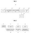
- FIG. 1 is a block diagram showing an ultrasound system constructed in accordance with the present invention.
- the ultrasound system 100 includes a probe 110, a beam forming and signal processing unit 120, a volume data forming and reconstructing unit 130, an input unit 140, a processor 150 and a display unit 160.
- the ultrasound system 100 may further include a storage unit (not shown) for storing various data.
- the probe 110 may include an array transducer containing a plurality of transducer elements for transmitting ultrasound signals to a target object and receiving ultrasound echo signals from the target object.
- the target object may contain a periodically moving object.
- the transducer elements may convert the ultrasound echo signals into electrical reception signals.
- the beam forming and signal processing unit 120 may be operable to focus the electrical reception signals, and amplify and process the focused signals.
- the volume data forming and reconstructing unit 130 may form volume data for a 3-dimensional ultrasound image of the target object based on the focused signals received from the beam forming and signal processing unit 120.
- the volume data forming and reconstructing unit 130 may be operable to calculate a beat period of the moving object contained in the target object and reconstruct the volume data based on the calculated beat period.
- the beat period may be a heartbeat period.
- the volume data forming and reconstructing unit 130 may include a volume data forming unit 131, a pre-processing unit 132, a region of interest (ROI) setting unit 133, a volume of interest (VOI) setting unit 134, a correlation coefficient calculating unit 135, a period setting unit 136 and a volume data reconstructing unit 137.
- ROI region of interest
- VOI volume of interest
- the volume data forming unit 131 may form volume data for forming a 3-dimensional ultrasound image of the target object based on the focused signals, which are consecutively received from the beam forming and signal processing unit 120.
- the pre-processing unit 132 may be operable to reduce or remove noises from an ultrasound image.
- the noise reduction may preferably be performed upon at least one of horizontal and vertical cut plane images 210 and 220, which are obtained by horizontally or vertically cutting the ultrasound volume data, as shown in FIG. 3 .
- the volume data may be cut either in the horizontal or vertical direction along its center planes.
- the noise reduction is assumed to be performed upon the horizontal cut plane image 210.
- the pre-processing unit 132 may decompose the horizontal cut plane image in a wavelet domain into sub-band images HH, HL, LH and LL (wavelet transform).
- the pre-processing unit 132 may calculate wavelet coefficients in each sub-band image.
- the pre-processing unit 132 may perform soft-thresholding upon the calculated wavelet coefficients. That is, if the calculated wavelet coefficient is smaller than the threshold, then the pre-processing unit 132 may reset the wavelet coefficient to zero. If the wavelet coefficient is greater than the threshold, then the pre-processing unit 132 may subtract the threshold from the wavelet coefficient to thereby reset the wavelet coefficient.
- the soft-thresholding may not be carried out for the sub-band image LL, wherein the sub-band image LL represents low frequency (vertical) - low frequency (horizontal) image.
- the soft-thresholding can be carried out by the following equation in accordance with the present invention.
- W j f(t) represents a coefficient of a high frequency at a j th level decomposed in the wavelet domain
- sign () represents a sign of the coefficients
- Th represents a threshold having a constant value
- W j f ⁇ (t) represents a resulting wavelet coefficient from performing the soft-thresholding.
- the pre-processing unit 132 may reconstruct the decomposed images through inverse wavelet transform to thereby obtain the horizontal cut plane image with the noises reduced.
- FIG. 4 shows an original horizontal cut plane image obtained from the ultrasound volume data
- FIG. 5 shows a horizontal cut plane image obtained by reconstructing the sub-band images with the soft-thresholding performed in the pre-processing unit 132.
- the ROI setting unit 133 may set a region of interest (ROI) on the pre-processed horizontal cut plane image.
- ROI region of interest
- the ROI setting unit 133 may perform horizontal projection upon the pre-processed horizontal cut plane image to thereby obtain projected values that are sum of the brightness of all pixels along horizontal projection lines, as shown in FIG. 6 .
- the ROI setting unit 133 may calculate a mean value of the projected values and calculate positions n T and n B , which represent a vertical position of a projected value located in the most left side among the projected values smaller than the mean value and a vertical position of a projected value located in the most-right side among the projected values smaller than the mean value, respectively.
- Positions n T and n B may be calculated by using equation (2) shown below.
- n T min n n
- n B max n n
- f n represents a horizontally projected signal
- Mean represents a mean of the projected values.
- the positions n T and n B may be used as boundaries of the ROI.
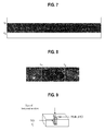
- the ROI setting unit 133 may use the boundaries n T and n B of ROI to mask the horizontal cut plane image, thereby removing regions that are located outside the boundaries n T and n B , as shown in FIG. 7 .
- An example of the ROI set on an arbitrary frame in the ultrasound volume data is shown in FIG. 8 .
- the VOI setting unit 134 may be operable to set a volume of interest (VOI) in the volume data by using the ROI.
- the VOI setting unit 134 may select frames including the moving object within the target object.
- a plurality of vertical lines may be set in the horizontal cut plane image and standard deviation of brightness of the vertical lines may be used to select the frames.
- the moving object may be the heart of a fetus. Since the heart includes valves (displayed in a bright portion) as well as atria and ventricles (displayed in a dark portion), the image of the heart relatively has a high contrast.
- the vertical lines including a heart region may be found by using the standard deviation of the brightness of the vertical lines.
- the vertical lines included in the heart region may be more accurately selected by considering standard deviation of the neighboring vertical lines. This is to allow the vertical lines, which are not included in the heart region and have a high contrast, to be excluded from the vertical lines included in the heart region.
- the VOI setting unit 134 may select three vertical lines having a maximum standard deviation difference between the neighboring vertical lines in order to detect reference frames for setting VOIs.
- Pseudo codes of algorithm for selecting three vertical lines are as follows:
- ⁇ k i represents the standard deviation of the vertical lines existing on the horizontal cut plane image
- k i represents an order of the vertical lines (identical to that of the frames in the volume)
- K represents the number of total frames (identical to that of total vertical lines)
- C is a constant.
- the VOI setting unit 134 may be operable to collect the neighboring frames of each of the three reference frames and set the VOIs with the ROIs set on the collected frames.
- FIG. 9 shows an example of the VOI set in the volume data.
- the length of the VOI on a time axis may be determined according to frames positioned at the right and left sides of the reference frame.
- the width of the VOI is defined according to the width of the ROI set in the ROI setting unit 133.
- the VOI set in the VOI setting unit 134 can be expressed as the following equation.
- V k ⁇ i f ROI k , k ⁇ i - 1 ⁇ k ⁇ k ⁇ i + 1 for each k ⁇ i
- k ⁇ i represents the positions of three vertical lines having a maximum standard deviation in the horizontal cut plane image (i.e., frame positions)
- f ROI ( k ) represents the ROI in a k th frame
- V k ⁇ i represents the VOI formed by combining the ROI within the reference frame with those of neighboring frames.
- the VOI setting unit 134 may set three VOIs for three reference frames.
- the correlation coefficient curve calculating unit 135 may calculate the correlation coefficient curves for a constant time by using the VOIs set in the VOI setting unit 134.
- E [ V k ] and E [ V k ⁇ i ] represent the average of brightness within VOIs at k and k ⁇ i positions
- ⁇ v k and ⁇ v k ⁇ i represent the mean of standard deviation of brightness within the VOIs at k and k ⁇ i positions
- an ⁇ i ( V k, V k ⁇ i ) represents a correlation coefficient between the VOI at a k position and the VOI at a k ⁇ i position.
- the correlation coefficient curve calculating unit 135 may calculate the three correlation coefficient curves for three VOIs, which are set in the VOI setting unit 134. The reason for calculating the three correlation curves is to utilize the local characteristics in volume data.
- FIG. 10 is a graph showing the three correlation coefficient curves obtained in the correlation coefficient curve calculating unit 135.
- the period setting unit 136 may detect a heartbeat period.
- FIG. 11 is a block diagram showing a procedure for detecting the global period in the period setting unit 136.
- the period setting unit 136 may include a filtering unit 310, a gradient calculating unit 320 and a zero cross point detecting unit 330.
- the filtering unit 310 may be operable to filter the correlation coefficient curves to reduce noises included therein.
- a low pass filter may be used in the filtering unit 310.
- the gradient calculating unit 320 may calculate the gradients in the filtered correlation coefficient curves.
- the zero cross point detecting unit 330 may detect zero cross points whose gradients are changed from positive to negative.
- the period setting unit 136 may set candidate periods by using right and left zero crossing points of a central zero crossing point at each of the three filtered correlation coefficient curves. That is, the period setting unit 136 may calculate six candidate periods of the heartbeat (Pn).
- FIG. 12 shows an example of detecting the heartbeat period in the filtered correlation coefficient curve.
- the period setting unit 136 may select one period (P 3 ) having the highest frequency among the candidate periods (P 1 , P 2 , P 3 ) and then set the selected period to a global period of the heartbeat.
- the period selection can be expressed as the following equation.
- p FHB mode p n
- p n represents six candidate periods detected from three correlation coefficient curves formed from the VOI
- p FHB represents a period having the highest frequency among the six candidate periods.
- the period setting unit 136 may set a new reference frame, which is away from the reference frame by the global period, and then set a search region including a predetermined number of frames adjacent to the new reference frame.
- the period setting unit 136 may be operable to calculate the correlation coefficients between the VOI in the reference frame and each VOI in each frame included in the search region. If a correlation coefficient of an arbitrary frame is maximal among the correlation coefficients of the frames included in the search region and the correlation of the arbitrary frame is greater than a value obtained by multiplying a predetermined weight by an average of the correlation coefficients, then an interval between the arbitrary frame and the reference frame is determined as the local period. Thereafter, the period setting unit 136 may set a new reference frame, which is away from the arbitrary frame by the global period. Then, the above process for calculating the local period is repeatedly carried out to the end of the volume data, thereby obtaining total local periods.
- the ultrasound data reconstructing unit 137 may perform a linear interpolation for the frames included within each local period by using the global period set in the period setting unit 136.
- an interpolation frame ( I ') is calculated as the following equation using the ratio (r) of the local period to the global period.
- I ⁇ ⁇ 2 ⁇ I n + ⁇ 1 ⁇ I n + 1
- I n and I n +1 represent frames adjacent to the interpolation frame I'
- ⁇ 1 and ⁇ 2 represent the distances between the adjacent frames and the interpolation frames
- ⁇ 1 and ⁇ 2 are determined according to the ratio (r) of the local period to the global period.
- the ultrasound data reconstructing unit 137 may reconstruct the interpolated volume data to provide a 3-dimensional ultrasound image showing a figure of the heartbeat.
- FIG. 13 shows a procedure for reconstructing the interpolated volume data. As shown in FIG. 13 , twenty-six local periods A to Z may exist in one volume data. Assuming that six frames are contained in one local period in the volume data as shown in FIG. 13 , the reconstructed volume data includes six sub volumes. Each of the sub volumes consists of 26 frames A i to Z i .
- the ultrasound system may further include a motion compensating unit.
- the motion compensating unit compensates for the motion of the expectant mother or the fetus by matching the brightness of pixels between a previously set VOI and a currently set VOI.
- the motion compensating unit may be operable to calculate the motion vectors by summing the absolute differences of brightness of pixels between the previously set VOI and the currently set VOI.
- the VOI at a n th frame is expressed as V n (m)
- the VOI at a next frame can be expressed as V n (m+1).
- a variable m represents the combination of n-1, n and n+1.
- the motion compensating unit may move V n (m) up, down, right and left (i, j), and then calculate the absolute differences of brightness of pixels between V n (m) and V n (m+1) at each position.
- a motion vector may be estimated at a position where the absolute difference is minimal. The sum of the absolute difference is calculated as the following equation.
- W represents a predefined motion estimated range
- K represents a total number of the frames
- i, j represent motion displacements
- k, l represent the position of a pixel in the frame included in VOI
- m represents the number of the frames.
- the input unit 140 may receive setup information from a user.
- the setup information may include reference frame setup information, M-mode line setup information and rotation setup information of a 3-dimensional ultrasound image.
- the processor 150 may be operable to form an M-mode image signal.
- the M-mode image may be formed by using the reconstructed volume data based on the setup information inputted from a user through the input unit 140.
- the processor 150 may form a reference frame image 410 by using the reconstructed volume data based on the reference frame setup information as illustrated in FIG. 14 . Then, the processor 150 may extract data corresponding to M-mode lines 421, 422 and 423, which are set on the reference frame, based on the M-mode line setup information inputted through the input unit 140. The processor 150 may form M-mode images 431, 432 and 433 corresponding to the M-mode lines based on the extracted data. Although it is described that three M-mode lines are set on the reference frame image for ease of explanation in accordance with one embodiment of the present invention, the M-mode lines may be arbitrarily set on the reference frame image in accordance with another embodiment.
- a different reference frame image may be formed based on reference frame setup information while the previously formed M-mode images 431, 432 and 433 are displayed.
- at least one M-mode line may be set on each of the different reference frame images.
- at least one M-mode image corresponding to the M-mode line may be formed by extracting data from the reconstructed volume data.
- reference frame setup information for forming a plurality of reference frame images may be inputted through the input unit 140.
- the processor 150 may form reference frame images by using the reconstructed volume data based on the reference frame setup information.
- At least one M-mode line may be set on each reference frame image.
- the processor 150 may extract data corresponding to the M-mode line set on each reference frame image from the reconstructed volume data and forms M-mode image signals for M-mode images based on the extracted data.
- the processor 150 may form a 3-dimensional ultrasound image 510 as illustrated in FIG. 15 by using the reconstructed volume data.
- M-mode lines 521, 522 and 523 may be set on the 3-dimensional ultrasound image 510 based on M-mode line setup information inputted from the user through the input unit 140.
- the processor 150 may extract data corresponding to the M-mode lines 521, 522 and 523 set on the 3-dimensional ultrasound image and form M-mode images based on the extracted data. Although the three M-mode lines are set, the number of the M-mode lines is not limited thereto.
- the processor 150 may be operable to rotate the 3-dimensional ultrasound image. Thereafter, M-mode lines may be set on the rotated 3-dimensional ultrasound image and the processor 150 may form M-mode images corresponding to the M-mode lines set on the rotated 3-dimensional ultrasound image.
- the display unit 160 may receive the reference frame image signals, the 3-dimensional ultrasound image signals and the M-mode image signals to display the reference frame image, the 3-dimensional ultrasound image and the M-mode image.
- the present invention may display M-mode images for different portions of the target object without moving a probe.
- an ultrasound system including: a probe operable to transmit ultrasound signals to a target object containing a periodically moving object and receive ultrasound echo signals reflected from the target object; a volume data forming and reconstructing unit operable to form volume data based on the ultrasound echo signals, the volume data forming and reconstructing unit being configured to determine a beat period of the moving object and reconstruct the volume data based on the beat period; a processor operable to form at least one reference image based on the reconstructed volume data and set a plurality of M-mode lines on the reference image, the processor being configured to form a plurality of M-mode images by extracting data corresponding to the M-mode lines from the reconstructed volume data; and a display unit to display the reference image, the M-mode lines and the M-mode images, one at a time, simultaneously or sequentially.
- a method of forming an ultrasound image including: a) transmitting ultrasound signals to a target object containing a periodically moving object and receiving ultrasound echo signals reflected from the target object; b) forming volume data based on the ultrasound echo signals; c) determining a beat period of the moving object and reconstructing the volume data based on the beat period; d) forming at least one reference image based on the reconstructed volume data; e) setting a plurality of M-mode lines on the reference image; f) forming a plurality of M-mode images by extracting data corresponding to the plurality of M-mode lines from the reconstructed volume data; and g) displaying the reference image, the M-mode lines and the M-mode images, one at a time, simultaneously or sequentially.
- any reference in this specification to "one embodiment,” “an embodiment,” “example embodiment,” etc. means that a particular feature, structure or characteristic described in connection with the embodiment is included in at least one embodiment of the present invention.
- the appearances of such phrases in various places in the specification are not necessarily all referring to the same embodiment.
Landscapes
- Health & Medical Sciences (AREA)
- Life Sciences & Earth Sciences (AREA)
- Engineering & Computer Science (AREA)
- Physics & Mathematics (AREA)
- Biophysics (AREA)
- Surgery (AREA)
- Veterinary Medicine (AREA)
- Pathology (AREA)
- Biomedical Technology (AREA)
- Heart & Thoracic Surgery (AREA)
- Medical Informatics (AREA)
- Molecular Biology (AREA)
- Nuclear Medicine, Radiotherapy & Molecular Imaging (AREA)
- Animal Behavior & Ethology (AREA)
- General Health & Medical Sciences (AREA)
- Public Health (AREA)
- Radiology & Medical Imaging (AREA)
- Computer Networks & Wireless Communication (AREA)
- General Physics & Mathematics (AREA)
- Radar, Positioning & Navigation (AREA)
- Remote Sensing (AREA)
- Physiology (AREA)
- Cardiology (AREA)
- Computer Vision & Pattern Recognition (AREA)
- Computer Graphics (AREA)
- General Engineering & Computer Science (AREA)
- Ultra Sonic Daignosis Equipment (AREA)
Abstract
Description
- The present application claims priority from Korean Patent Application No.
10-2007-0022982 filed on March 8, 2007 - The present invention generally relates to ultrasound systems, and more particularly to an ultrasound system and a method of forming ultrasound images.
- An ultrasound system has become an important and popular diagnostic tool due to its non-invasive and non-destructive nature. Modern high-performance ultrasound imaging diagnostic systems and techniques are commonly used to produce two- or three-dimensional images of internal features of patients.
- The ultrasound system generally uses a probe comprising an array of transducer elements to transmit and receive ultrasound signals. The ultrasound system forms an image of human internal tissues by electrically exciting transducer elements to generate ultrasound signals that travel into the body. Echoes reflected from tissues and organs return to the transducer elements and are converted into electrical signals, which are amplified and processed to produce an ultrasound image data.
- The ultrasound system provides an M-mode (motion mode) image periodically showing the motion of a target object. The ultrasound system first displays a B-mode image of the target object and then displays bio-information of the target object, which corresponds to an M-mode line set on the B-mode image, over the elapse of time.
- In the conventional ultrasound system, however, a probe should be moved to observe different portions of a target object. Thus, there are problems in that B-mode and M-mode images for different portions of the target object cannot be provided at the same time. Further, it takes a long time to form the B-mode and M-mode images for different portions of the target object.
-
-
FIG. 1 is a block diagram showing an ultrasound system in accordance with one embodiment of the present invention. -
FIG. 2 is a block diagram showing a volume data forming and reconstructing unit in accordance with one embodiment of the present invention. -
FIG. 3 is a schematic diagram showing cut plane images in volume data. -
FIG. 4 is a photo showing a horizontal cut plane image in volume data. -
FIG. 5 is a photo showing an image obtained by performing soft-thresholding upon a horizontal cut plane image. -
FIG. 6 is a graph showing projected values obtained through the horizontal projection of a horizontal cut plane image. -
FIG. 7 is a photo showing an image with a horizontal cut plane image masked by a mask defining ROI boundaries. -
FIG. 8 is a photo showing the ROI set in a frame. -
FIG. 9 is a schematic diagram showing an example of the VOI set in ultrasound volume data. -
FIG. 10 is a graph showing three correlation coefficient curves. -
FIG. 11 is a block diagram showing a procedure of detecting a global period of heartbeat. -
FIG. 12 is a diagram showing an example of detecting a global period of heartbeat. -
FIG. 13 is a diagram showing a procedure of reconstructing ultrasound volume data in accordance with one embodiment of the present invention. -
FIG. 14 is a schematic diagram showing a reference frame image and M-mode images in accordance with one embodiment of the present invention. -
FIG. 15 is a schematic diagram showing a 3-dimensional ultrasound image and M-mode images in accordance with another embodiment of the present invention. -
FIG. 1 is a block diagram showing an ultrasound system constructed in accordance with the present invention. As shown inFIG. 1 , theultrasound system 100 includes aprobe 110, a beam forming andsignal processing unit 120, a volume data forming and reconstructingunit 130, aninput unit 140, aprocessor 150 and adisplay unit 160. Theultrasound system 100 may further include a storage unit (not shown) for storing various data. - The
probe 110 may include an array transducer containing a plurality of transducer elements for transmitting ultrasound signals to a target object and receiving ultrasound echo signals from the target object. The target object may contain a periodically moving object. The transducer elements may convert the ultrasound echo signals into electrical reception signals. - The beam forming and
signal processing unit 120 may be operable to focus the electrical reception signals, and amplify and process the focused signals. The volume data forming and reconstructingunit 130 may form volume data for a 3-dimensional ultrasound image of the target object based on the focused signals received from the beam forming andsignal processing unit 120. The volume data forming and reconstructingunit 130 may be operable to calculate a beat period of the moving object contained in the target object and reconstruct the volume data based on the calculated beat period. When the object is a heart, the beat period may be a heartbeat period. - As shown in
FIG. 2 , the volume data forming and reconstructingunit 130 may include a volumedata forming unit 131, apre-processing unit 132, a region of interest (ROI) settingunit 133, a volume of interest (VOI) settingunit 134, a correlationcoefficient calculating unit 135, aperiod setting unit 136 and a volumedata reconstructing unit 137. - The volume
data forming unit 131 may form volume data for forming a 3-dimensional ultrasound image of the target object based on the focused signals, which are consecutively received from the beam forming andsignal processing unit 120. - The
pre-processing unit 132 may be operable to reduce or remove noises from an ultrasound image. The noise reduction may preferably be performed upon at least one of horizontal and verticalcut plane images FIG. 3 . Generally, since data corresponding to an object desired for observation are positioned at a center portion of the volume data, the volume data may be cut either in the horizontal or vertical direction along its center planes. As discussed below, the noise reduction is assumed to be performed upon the horizontalcut plane image 210. - The
pre-processing unit 132 may decompose the horizontal cut plane image in a wavelet domain into sub-band images HH, HL, LH and LL (wavelet transform). Thepre-processing unit 132 may calculate wavelet coefficients in each sub-band image. Thepre-processing unit 132 may perform soft-thresholding upon the calculated wavelet coefficients. That is, if the calculated wavelet coefficient is smaller than the threshold, then thepre-processing unit 132 may reset the wavelet coefficient to zero. If the wavelet coefficient is greater than the threshold, then thepre-processing unit 132 may subtract the threshold from the wavelet coefficient to thereby reset the wavelet coefficient. The soft-thresholding may not be carried out for the sub-band image LL, wherein the sub-band image LL represents low frequency (vertical) - low frequency (horizontal) image. The soft-thresholding can be carried out by the following equation in accordance with the present invention.
wherein, Wjf(t) represents a coefficient of a high frequency at a jth level decomposed in the wavelet domain, sign() represents a sign of the coefficients, Th represents a threshold having a constant value, and Wjf̂(t) represents a resulting wavelet coefficient from performing the soft-thresholding. Thereafter, thepre-processing unit 132 may reconstruct the decomposed images through inverse wavelet transform to thereby obtain the horizontal cut plane image with the noises reduced. -
FIG. 4 shows an original horizontal cut plane image obtained from the ultrasound volume data, whereasFIG. 5 shows a horizontal cut plane image obtained by reconstructing the sub-band images with the soft-thresholding performed in thepre-processing unit 132. - The
ROI setting unit 133 may set a region of interest (ROI) on the pre-processed horizontal cut plane image. In order to set the ROI, theROI setting unit 133 may perform horizontal projection upon the pre-processed horizontal cut plane image to thereby obtain projected values that are sum of the brightness of all pixels along horizontal projection lines, as shown inFIG. 6 . TheROI setting unit 133 may calculate a mean value of the projected values and calculate positions nT and nB, which represent a vertical position of a projected value located in the most left side among the projected values smaller than the mean value and a vertical position of a projected value located in the most-right side among the projected values smaller than the mean value, respectively. Positions nT and nB may be calculated by using equation (2) shown below.

- wherein, fn represents a horizontally projected signal, and Mean represents a mean of the projected values. The positions nT and nB may be used as boundaries of the ROI.
- The
ROI setting unit 133 may use the boundaries nT and nB of ROI to mask the horizontal cut plane image, thereby removing regions that are located outside the boundaries nT and nB , as shown inFIG. 7 . An example of the ROI set on an arbitrary frame in the ultrasound volume data is shown inFIG. 8 . - The
VOI setting unit 134 may be operable to set a volume of interest (VOI) in the volume data by using the ROI. TheVOI setting unit 134 may select frames including the moving object within the target object. A plurality of vertical lines may be set in the horizontal cut plane image and standard deviation of brightness of the vertical lines may be used to select the frames. For example, the moving object may be the heart of a fetus. Since the heart includes valves (displayed in a bright portion) as well as atria and ventricles (displayed in a dark portion), the image of the heart relatively has a high contrast. Thus, the vertical lines including a heart region may be found by using the standard deviation of the brightness of the vertical lines. Also, since the contrast of neighboring vertical lines within the heart region rapidly changes, the vertical lines included in the heart region may be more accurately selected by considering standard deviation of the neighboring vertical lines. This is to allow the vertical lines, which are not included in the heart region and have a high contrast, to be excluded from the vertical lines included in the heart region. - The
VOI setting unit 134 may select three vertical lines having a maximum standard deviation difference between the neighboring vertical lines in order to detect reference frames for setting VOIs. Pseudo codes of algorithm for selecting three vertical lines are as follows: - DO i=0,1,2
-
Step 1.
- Step 2. reject the range of [ki-C,Ki +C] in the search range
- END DO
- wherein, σk
i represents the standard deviation of the vertical lines existing on the horizontal cut plane image, ki represents an order of the vertical lines (identical to that of the frames in the volume), K represents the number of total frames (identical to that of total vertical lines), and C is a constant. Three frames including the three vertical lines obtained by the above algorithm are used as the reference frames for setting three VOIs. - The
VOI setting unit 134 may be operable to collect the neighboring frames of each of the three reference frames and set the VOIs with the ROIs set on the collected frames.FIG. 9 shows an example of the VOI set in the volume data. InFIG. 9 , the length of the VOI on a time axis may be determined according to frames positioned at the right and left sides of the reference frame. The width of the VOI is defined according to the width of the ROI set in theROI setting unit 133. The VOI set in theVOI setting unit 134 can be expressed as the following equation.
- wherein, k̂i represents the positions of three vertical lines having a maximum standard deviation in the horizontal cut plane image (i.e., frame positions), fROI (k) represents the ROI in a kth frame, and Vk̂ i represents the VOI formed by combining the ROI within the reference frame with those of neighboring frames. The
VOI setting unit 134 may set three VOIs for three reference frames. - The correlation coefficient
curve calculating unit 135 may calculate the correlation coefficient curves for a constant time by using the VOIs set in theVOI setting unit 134. The correlation coefficient curve is calculated through the following equation.
- wherein, E[Vk ] and E[Vk̂ i ] represent the average of brightness within VOIs at k and k̂i positions, σv
k and σv k̂i represent the mean of standard deviation of brightness within the VOIs at k and k̂i positions, an ρi (Vk,Vk̂i ) represents a correlation coefficient between the VOI at a k position and the VOI at a k̂i position. The correlation coefficientcurve calculating unit 135 may calculate the three correlation coefficient curves for three VOIs, which are set in theVOI setting unit 134. The reason for calculating the three correlation curves is to utilize the local characteristics in volume data.FIG. 10 is a graph showing the three correlation coefficient curves obtained in the correlation coefficientcurve calculating unit 135. - The
period setting unit 136 may detect a heartbeat period.FIG. 11 is a block diagram showing a procedure for detecting the global period in theperiod setting unit 136. Theperiod setting unit 136 may include afiltering unit 310, agradient calculating unit 320 and a zero crosspoint detecting unit 330. Thefiltering unit 310 may be operable to filter the correlation coefficient curves to reduce noises included therein. A low pass filter may be used in thefiltering unit 310. Thegradient calculating unit 320 may calculate the gradients in the filtered correlation coefficient curves. The zero crosspoint detecting unit 330 may detect zero cross points whose gradients are changed from positive to negative. - Subsequently, the
period setting unit 136 may set candidate periods by using right and left zero crossing points of a central zero crossing point at each of the three filtered correlation coefficient curves. That is, theperiod setting unit 136 may calculate six candidate periods of the heartbeat (Pn).FIG. 12 shows an example of detecting the heartbeat period in the filtered correlation coefficient curve. Theperiod setting unit 136 may select one period (P3) having the highest frequency among the candidate periods (P1, P2, P3) and then set the selected period to a global period of the heartbeat. The period selection can be expressed as the following equation.
- wherein, pn represents six candidate periods detected from three correlation coefficient curves formed from the VOI, and pFHB represents a period having the highest frequency among the six candidate periods.
- Subsequently, the
period setting unit 136 may set a new reference frame, which is away from the reference frame by the global period, and then set a search region including a predetermined number of frames adjacent to the new reference frame. Theperiod setting unit 136 may be operable to calculate the correlation coefficients between the VOI in the reference frame and each VOI in each frame included in the search region. If a correlation coefficient of an arbitrary frame is maximal among the correlation coefficients of the frames included in the search region and the correlation of the arbitrary frame is greater than a value obtained by multiplying a predetermined weight by an average of the correlation coefficients, then an interval between the arbitrary frame and the reference frame is determined as the local period. Thereafter, theperiod setting unit 136 may set a new reference frame, which is away from the arbitrary frame by the global period. Then, the above process for calculating the local period is repeatedly carried out to the end of the volume data, thereby obtaining total local periods. - The ultrasound
data reconstructing unit 137 may perform a linear interpolation for the frames included within each local period by using the global period set in theperiod setting unit 136. The ultrasounddata reconstructing unit 137 may be operable to calculate a ratio (r) of the local period to the global period as the following equation.
- Thereafter, an interpolation frame (I') is calculated as the following equation using the ratio (r) of the local period to the global period.

- wherein, In and I n+1 represent frames adjacent to the interpolation frame I', Δ1 and Δ2 represent the distances between the adjacent frames and the interpolation frames, and wherein Δ1 and Δ2 are determined according to the ratio (r) of the local period to the global period. This interpolation process is carried out for frames included in all local periods such that the same number of frames is contained in each local period.
- The ultrasound
data reconstructing unit 137 may reconstruct the interpolated volume data to provide a 3-dimensional ultrasound image showing a figure of the heartbeat.FIG. 13 shows a procedure for reconstructing the interpolated volume data. As shown inFIG. 13 , twenty-six local periods A to Z may exist in one volume data. Assuming that six frames are contained in one local period in the volume data as shown inFIG. 13 , the reconstructed volume data includes six sub volumes. Each of the sub volumes consists of 26 frames Ai to Zi. - Further, when the 3-dimensional volume data are acquired by scanning the target object, the object (e.g., expectant mother or fetus) may be moved. This makes it difficult to accurately detect the heartbeat period of the fetus. Accordingly, the ultrasound system may further include a motion compensating unit. The motion compensating unit compensates for the motion of the expectant mother or the fetus by matching the brightness of pixels between a previously set VOI and a currently set VOI. The motion compensating unit may be operable to calculate the motion vectors by summing the absolute differences of brightness of pixels between the previously set VOI and the currently set VOI. For example, assuming that the VOI at a nth frame is expressed as Vn(m), the VOI at a next frame can be expressed as Vn(m+1). In such a case, a variable m represents the combination of n-1, n and n+1. The motion compensating unit may move Vn(m) up, down, right and left (i, j), and then calculate the absolute differences of brightness of pixels between Vn(m) and Vn(m+1) at each position. A motion vector may be estimated at a position where the absolute difference is minimal. The sum of the absolute difference is calculated as the following equation.

for -W ≤i,j<W, 1≤n<K-1 - wherein, W represents a predefined motion estimated range, K represents a total number of the frames, i, j represent motion displacements, k, l represent the position of a pixel in the frame included in VOI, and m represents the number of the frames.
- The
input unit 140 may receive setup information from a user. The setup information may include reference frame setup information, M-mode line setup information and rotation setup information of a 3-dimensional ultrasound image. Theprocessor 150 may be operable to form an M-mode image signal. The M-mode image may be formed by using the reconstructed volume data based on the setup information inputted from a user through theinput unit 140. - The
processor 150 may form areference frame image 410 by using the reconstructed volume data based on the reference frame setup information as illustrated inFIG. 14 . Then, theprocessor 150 may extract data corresponding to M-mode lines input unit 140. Theprocessor 150 may form M-mode images - Further, a different reference frame image may be formed based on reference frame setup information while the previously formed M-
mode images - In accordance with another embodiment of the present invention, reference frame setup information for forming a plurality of reference frame images may be inputted through the
input unit 140. Theprocessor 150 may form reference frame images by using the reconstructed volume data based on the reference frame setup information. At least one M-mode line may be set on each reference frame image. Theprocessor 150 may extract data corresponding to the M-mode line set on each reference frame image from the reconstructed volume data and forms M-mode image signals for M-mode images based on the extracted data. - In accordance with yet another embodiment of the present invention, the
processor 150 may form a 3-dimensional ultrasound image 510 as illustrated inFIG. 15 by using the reconstructed volume data. M-mode lines dimensional ultrasound image 510 based on M-mode line setup information inputted from the user through theinput unit 140. Theprocessor 150 may extract data corresponding to the M-mode lines input unit 140, then theprocessor 150 may be operable to rotate the 3-dimensional ultrasound image. Thereafter, M-mode lines may be set on the rotated 3-dimensional ultrasound image and theprocessor 150 may form M-mode images corresponding to the M-mode lines set on the rotated 3-dimensional ultrasound image. - The
display unit 160 may receive the reference frame image signals, the 3-dimensional ultrasound image signals and the M-mode image signals to display the reference frame image, the 3-dimensional ultrasound image and the M-mode image. - As mentioned above, the present invention may display M-mode images for different portions of the target object without moving a probe.
- In accordance with one embodiment of the present invention, there is provided an ultrasound system, including: a probe operable to transmit ultrasound signals to a target object containing a periodically moving object and receive ultrasound echo signals reflected from the target object; a volume data forming and reconstructing unit operable to form volume data based on the ultrasound echo signals, the volume data forming and reconstructing unit being configured to determine a beat period of the moving object and reconstruct the volume data based on the beat period; a processor operable to form at least one reference image based on the reconstructed volume data and set a plurality of M-mode lines on the reference image, the processor being configured to form a plurality of M-mode images by extracting data corresponding to the M-mode lines from the reconstructed volume data; and a display unit to display the reference image, the M-mode lines and the M-mode images, one at a time, simultaneously or sequentially.
- In accordance with another embodiment of the present invention, there is provided a method of forming an ultrasound image, including: a) transmitting ultrasound signals to a target object containing a periodically moving object and receiving ultrasound echo signals reflected from the target object; b) forming volume data based on the ultrasound echo signals; c) determining a beat period of the moving object and reconstructing the volume data based on the beat period; d) forming at least one reference image based on the reconstructed volume data; e) setting a plurality of M-mode lines on the reference image; f) forming a plurality of M-mode images by extracting data corresponding to the plurality of M-mode lines from the reconstructed volume data; and g) displaying the reference image, the M-mode lines and the M-mode images, one at a time, simultaneously or sequentially.
- Any reference in this specification to "one embodiment," "an embodiment," "example embodiment," etc. means that a particular feature, structure or characteristic described in connection with the embodiment is included in at least one embodiment of the present invention. The appearances of such phrases in various places in the specification are not necessarily all referring to the same embodiment. Further, when a particular feature, structure or characteristic is described in connection with any embodiment, it is submitted that it is within the purview of one skilled in the art to effect such feature, structure or characteristic in connection with other ones of the embodiments.
- Although embodiments have been described with reference to a number of illustrative embodiments thereof, it should be understood that numerous other modifications and embodiments can be devised by those skilled in the art that will fall within the spirit and scope of the principles of this disclosure. More particularly, numerous variations and modifications are possible in the component parts and/or arrangements of the subject combination arrangement within the scope of the disclosure, the drawings and the appended claims. In addition to variations and modifications in the component parts and/or arrangements, alternative uses will also be apparent to those skilled in the art.
Claims (15)
- An ultrasound system (100), comprising:a probe (110) operable to transmit ultrasound signals to a target object containing a periodically moving object and receive ultrasound echo signals reflected from the target object;characterized by comprisinga volume data forming and reconstructing unit (130) operable to form volume data based on the ultrasound echo signals, the volume data forming and reconstructing unit (130) being configured to determine a beat period of the moving object and reconstruct the volume data based on the beat period;an input unit (140) to receive reference image setup information and M-mode line setup information from a user;a processor (150) operable to form a plurality of reference images corresponding to a plurality of cross-sections at different positions within the volume data by using the reconstructed volume data based on the reference image setup information, set at least one M-mode line on each of the reference images based on the M-mode line setup information, and form a plurality of M-mode images by extracting data corresponding to the at least one M-mode line from the reconstructed volume data; anda display unit (160) to display the plurality of reference images synchronizing with each other within the beat period, the at least one M-mode line on each of the reference images, and the plurality of M-mode images corresponding to the plurality of reference images.
- The ultrasound system (100) of Claim 1, wherein one of the reference images is a frame image.
- The ultrasound system (100) of Claim 1, wherein one of the reference images is a 3-dimensional image.
- The ultrasound system (100) of Claim 3, wherein the input unit further receives rotation information upon the 3-dimensional image and the processor rotates the 3-dimensional image based on the rotation information.
- The ultrasound system (100) of Claim 1, wherein the volume data forming and reconstructing unit (130) interpolates the volume data to contain a same number of frames in each beat period and reconstructs the interpolated volume data.
- The ultrasound system (100) of Claim 1, wherein the volume data forming and reconstructing unit (130) comprises
an ROI setting unit (120) for setting regions of interest (ROIs) to each of frames constituting the volume data acquired from a target object;
a VOI setting unit (130) for selecting a predetermined number of first reference frames from the ultrasound volume data and setting a predetermined number of volumes of interest (VOIs) by combining ROIs of the first reference frames with ROIs of frames adjacent to the reference frames;
a motion compensating unit for estimating a motion vector by using absolute differences of brightness of pixels between a previous VOI and a current VOI to compensate a motion of the target object by using the estimated motion vector;
a correlation coefficient curve calculating unit (140) for calculating correlation coefficient curves during a constant time on a time axis by using the VOIs;
a period setting unit (150) for setting a global period of the moving object based on the correlation coefficient curves and setting local periods in the volume data by setting a second reference frame off one of the first reference frames as far as the global period and calculating a correlation coefficient of frames adjacent to the second reference frame, thereby setting the local period determined based on an interval between the first reference frame and a frame having a maximum correlation coefficient among the adjacent frames; and
an ultrasound volume data reconstructing unit (160) for performing linear interpolation for the frames included within each local period by using a ratio of the local period to the global period and reconstructing the ultrasound volume data to have a plurality of sub volumes, each sub volume consisting of frames selected from frames of each local period. - The ultrasound system of Claim 6, wherein the period setting unit includes:a filtering unit (710) for filtering the correlation coefficient curve to reduce noises;a gradient calculation unit (720) for calculating gradients from the filtered correlation coefficient curve; anda zero crossing point detecting unit (730) for detecting zero crossing points changing a sign of the gradient from positive to negative and determining the global period based on intervals between the detected zero crossing points.
- The ultrasound system (100) of Claim 6, wherein the ROI setting unit sets ROI boundaries by using horizontal projection.
- A method of forming an ultrasound image, comprising:a) transmitting ultrasound signals to a target object containing a periodically moving object and receiving ultrasound echo signals reflected from the target object;b) forming volume data based on the ultrasound echo signals;
characterized by comprisingc) determining a beat period of the moving object and reconstructing the volume data based on the beat period;d) receiving reference image setup information from a user;e) forming a plurality of reference images corresponding to a plurality of cross-sections at different positions within the volume data by using the reconstructed volume data based on the reference image setup information;f) receiving M-mode line setup information from the user;g) setting at least one M-mode line on each of the reference images based on the M-mode line setup information;h) forming a plurality of M-mode images by extracting data corresponding to the at least one M-mode line from the reconstructed volume data; andi) displaying the plurality of reference images synchronizing with each other within the beat period, the at least one M-mode line on each of the reference images, and the plurality of M-mode images at the same time corresponding to the plurality of reference images. - The method of Claim 9, wherein one of the reference images is a frame image.
- The method of Claim 9, wherein one of the reference images is a 3-dimensional image.
- The method of Claim 11, further comprising receiving rotation information for the 3-dimensional image and rotating the 3-dimensional image based on the rotation information.
- The method of Claim 9, wherein the step c) comprises the steps of:interpolating the volume data to contain a same number of frames in each beat period and reconstructing the interpolated volume data.
- The method of Claim 9, wherein the step c) comprises the steps of:setting regions of interest (ROIs) to each of frames constituting the volume data acquired from a target object;selecting a predetermined number of first reference frames from the ultrasound volume data and setting a predetermined number of volumes of interest (VOIs) by combining ROIs of the first reference frames with ROIs of frames adjacent to the reference frames;estimating a motion vector by using absolute differences of brightness of pixels between a previous VOI and a current VOI to compensate a motion of the target object by using the estimated motion vector;calculating correlation coefficient curves during a constant time on a time axis by using the VOIs;setting a global period of the moving object based on the correlation coefficient curves and setting local periods in the volume data by setting a second reference frame off one of the first reference frames as far as the global period and calculating a correlation coefficient of frames adjacent to the second reference frame, thereby setting the local period determined based on an interval between the first reference frame and a frame having a maximum correlation coefficient among the adjacent frames; andperforming linear interpolation for the frames included within each local period by using a ratio of the local period to the global period and reconstructing the ultrasound volume data to have a plurality of sub volumes, each sub volume consisting of frames selected from frames of each local period.
- The method of Claim 14, wherein the setting the global period of the moving object comprises the steps of:filtering the correlation coefficient curve to reduce noises;calculating gradients from the filtered correlation coefficient curve; anddetecting zero crossing points changing a sign of the gradient from positive to negative and determining the global period based on intervals between the detected zero crossing points.
Applications Claiming Priority (2)
| Application Number | Priority Date | Filing Date | Title |
|---|---|---|---|
| KR20070022982A KR100961856B1 (en) | 2007-03-08 | 2007-03-08 | Ultrasound System and Method for Forming Ultrasound Images |
| EP20080004218 EP1967867A3 (en) | 2007-03-08 | 2008-03-07 | Ultrasound system and method of forming ultrasound images |
Related Parent Applications (1)
| Application Number | Title | Priority Date | Filing Date |
|---|---|---|---|
| EP20080004218 Division EP1967867A3 (en) | 2007-03-08 | 2008-03-07 | Ultrasound system and method of forming ultrasound images |
Publications (2)
| Publication Number | Publication Date |
|---|---|
| EP2955540A1 true EP2955540A1 (en) | 2015-12-16 |
| EP2955540B1 EP2955540B1 (en) | 2020-08-05 |
Family
ID=39512491
Family Applications (2)
| Application Number | Title | Priority Date | Filing Date |
|---|---|---|---|
| EP15169441.1A Active EP2955540B1 (en) | 2007-03-08 | 2008-03-07 | Ultrasound system and method of forming ultrasound images |
| EP20080004218 Ceased EP1967867A3 (en) | 2007-03-08 | 2008-03-07 | Ultrasound system and method of forming ultrasound images |
Family Applications After (1)
| Application Number | Title | Priority Date | Filing Date |
|---|---|---|---|
| EP20080004218 Ceased EP1967867A3 (en) | 2007-03-08 | 2008-03-07 | Ultrasound system and method of forming ultrasound images |
Country Status (4)
| Country | Link |
|---|---|
| US (3) | US8852105B2 (en) |
| EP (2) | EP2955540B1 (en) |
| JP (2) | JP2008220955A (en) |
| KR (1) | KR100961856B1 (en) |
Families Citing this family (16)
| Publication number | Priority date | Publication date | Assignee | Title |
|---|---|---|---|---|
| KR100961856B1 (en) | 2007-03-08 | 2010-06-09 | 주식회사 메디슨 | Ultrasound System and Method for Forming Ultrasound Images |
| US8271070B2 (en) * | 2007-10-04 | 2012-09-18 | Siemens Aktiengesellschaft | Method for monitoring myocardial wall thickness |
| KR101083936B1 (en) * | 2008-09-26 | 2011-11-15 | 삼성메디슨 주식회사 | Apparatus and method for processing ultrasound data |
| EP2189812B1 (en) * | 2008-11-25 | 2016-05-11 | Samsung Medison Co., Ltd. | Providing volume information on a periodically moving target object in an ultrasound system |
| JP5550411B2 (en) * | 2009-03-31 | 2014-07-16 | ミツビシ・エレクトリック・リサーチ・ラボラトリーズ・インコーポレイテッド | Method for estimating patient change patterns |
| JP5550931B2 (en) * | 2010-02-02 | 2014-07-16 | 日立アロカメディカル株式会社 | Ultrasonic diagnostic equipment |
| US8852106B2 (en) | 2009-04-13 | 2014-10-07 | Hitachi Aloka Medical, Ltd. | Ultrasound diagnostic apparatus |
| JP5588928B2 (en) * | 2011-06-03 | 2014-09-10 | 富士フイルム株式会社 | Ultrasonic diagnostic equipment |
| JP6420326B2 (en) * | 2013-10-04 | 2018-11-07 | コーニンクレッカ フィリップス エヌ ヴェKoninklijke Philips N.V. | Ultrasound system and method for automatic beat identification |
| CN104398272B (en) * | 2014-10-21 | 2017-09-19 | 无锡海斯凯尔医学技术有限公司 | Select the method and device and elastomeric check system of detection zone |
| KR102270718B1 (en) | 2014-11-11 | 2021-06-30 | 삼성메디슨 주식회사 | Untrasound dianognosis apparatus, operating method thereof and computer-readable storage medium |
| JP7127986B2 (en) * | 2014-11-18 | 2022-08-30 | コーニンクレッカ フィリップス エヌ ヴェ | A device for visualizing tissue properties |
| US9781405B2 (en) * | 2014-12-23 | 2017-10-03 | Mems Drive, Inc. | Three dimensional imaging with a single camera |
| US10646196B2 (en) | 2017-05-16 | 2020-05-12 | Clarius Mobile Health Corp. | Systems and methods for determining a heart rate of an imaged heart in an ultrasound image feed |
| EP3545849A1 (en) * | 2018-03-27 | 2019-10-02 | Koninklijke Philips N.V. | Apparatus, system and method for visualizing a periodically moving anatomy |
| CN117918885A (en) * | 2018-12-28 | 2024-04-26 | 深圳迈瑞生物医疗电子股份有限公司 | Fetal heart rate detection method, ultrasonic imaging device and storage medium |
Citations (4)
| Publication number | Priority date | Publication date | Assignee | Title |
|---|---|---|---|---|
| US5515856A (en) * | 1994-08-30 | 1996-05-14 | Vingmed Sound A/S | Method for generating anatomical M-mode displays |
| US20040111028A1 (en) * | 2002-08-12 | 2004-06-10 | Yasuhiko Abe | Ultrasound diagnosis apparatus and ultrasound image display method and apparatus |
| US20050049503A1 (en) * | 2003-08-28 | 2005-03-03 | Armin Schoisswohl | Method and apparatus for obtaining a volumetric scan of a periodically moving object |
| EP1757955A1 (en) * | 2005-08-24 | 2007-02-28 | Medison Co., Ltd. | Apparatus and method for processing an ultrasound image |
Family Cites Families (25)
| Publication number | Priority date | Publication date | Assignee | Title |
|---|---|---|---|---|
| JP4054402B2 (en) * | 1997-04-25 | 2008-02-27 | 株式会社東芝 | X-ray tomography equipment |
| US5570430A (en) * | 1994-05-31 | 1996-10-29 | University Of Washington | Method for determining the contour of an in vivo organ using multiple image frames of the organ |
| JP3894586B2 (en) | 1994-08-30 | 2007-03-22 | ビングメッド サウンド アクチスカベット | Method for generating anatomical M-mode display, ultrasound imaging device and method of using ultrasound imaging device |
| US6002738A (en) * | 1995-07-07 | 1999-12-14 | Silicon Graphics, Inc. | System and method of performing tomographic reconstruction and volume rendering using texture mapping |
| US5916168A (en) * | 1997-05-29 | 1999-06-29 | Advanced Technology Laboratories, Inc. | Three dimensional M-mode ultrasonic diagnostic imaging system |
| JP4116122B2 (en) | 1997-11-28 | 2008-07-09 | 株式会社東芝 | Ultrasonic diagnostic apparatus and ultrasonic image processing apparatus |
| JP2001046372A (en) | 1999-08-12 | 2001-02-20 | Toshiba Corp | Ultrasound image display |
| US6464642B1 (en) * | 1999-08-20 | 2002-10-15 | Kabushiki Kaisha Toshiba | Ultrasonic diagnosis apparatus |
| US6468216B1 (en) | 2000-08-24 | 2002-10-22 | Kininklijke Philips Electronics N.V. | Ultrasonic diagnostic imaging of the coronary arteries |
| EP1216473B1 (en) | 2000-08-24 | 2007-03-07 | Koninklijke Philips Electronics N.V. | Ultrasonic diagnostic imaging system with dynamic microbeamforming |
| KR200244563Y1 (en) | 2000-11-20 | 2001-09-25 | 고경영 | Steady output vertical axis wind turbine power system |
| WO2002061457A2 (en) * | 2001-01-30 | 2002-08-08 | Decharms R Christopher | Methods for physiological monitoring, training, exercise and regulation |
| JP2002306474A (en) | 2001-04-05 | 2002-10-22 | Ge Medical Systems Global Technology Co Llc | Ultrasonic imaging apparatus, ultrasonic photographing method, and program to make computer execute the method |
| JP3898978B2 (en) * | 2002-05-20 | 2007-03-28 | アロカ株式会社 | Ultrasonic diagnostic apparatus and ultrasonic image forming method |
| US20070167809A1 (en) * | 2002-07-22 | 2007-07-19 | Ep Medsystems, Inc. | Method and System For Estimating Cardiac Ejection Volume And Placing Pacemaker Electrodes Using Speckle Tracking |
| US20050245822A1 (en) * | 2002-07-22 | 2005-11-03 | Ep Medsystems, Inc. | Method and apparatus for imaging distant anatomical structures in intra-cardiac ultrasound imaging |
| US7211045B2 (en) * | 2002-07-22 | 2007-05-01 | Ep Medsystems, Inc. | Method and system for using ultrasound in cardiac diagnosis and therapy |
| JP4520235B2 (en) | 2003-07-09 | 2010-08-04 | パナソニック株式会社 | Ultrasonic diagnostic apparatus and ultrasonic diagnostic method |
| US20050288589A1 (en) * | 2004-06-25 | 2005-12-29 | Siemens Medical Solutions Usa, Inc. | Surface model parametric ultrasound imaging |
| JP4276595B2 (en) | 2004-08-18 | 2009-06-10 | アロカ株式会社 | Ultrasonic diagnostic equipment |
| KR100758737B1 (en) | 2005-08-23 | 2007-09-14 | 프리닉스 주식회사 | Printing system for centralized billing |
| US20070071295A1 (en) * | 2005-09-27 | 2007-03-29 | Siemens Medical Solutions Usa, Inc. | Orientation-based assessment of cardiac synchrony in medical imaging |
| KR100948047B1 (en) | 2006-06-29 | 2010-03-19 | 주식회사 메디슨 | Ultrasound System and Method for Forming Ultrasound Images |
| KR101310219B1 (en) | 2006-09-28 | 2013-10-14 | 삼성메디슨 주식회사 | Ultrasound system and method for providing a plurality of ultrasound images |
| KR100961856B1 (en) * | 2007-03-08 | 2010-06-09 | 주식회사 메디슨 | Ultrasound System and Method for Forming Ultrasound Images |
-
2007
- 2007-03-08 KR KR20070022982A patent/KR100961856B1/en active Active
-
2008
- 2008-03-07 US US12/044,292 patent/US8852105B2/en active Active
- 2008-03-07 EP EP15169441.1A patent/EP2955540B1/en active Active
- 2008-03-07 EP EP20080004218 patent/EP1967867A3/en not_active Ceased
- 2008-03-07 JP JP2008058386A patent/JP2008220955A/en active Pending
-
2012
- 2012-12-03 US US13/692,811 patent/US8721547B2/en active Active
-
2014
- 2014-02-05 US US14/173,612 patent/US20140155750A1/en not_active Abandoned
- 2014-12-12 JP JP2014251384A patent/JP6034851B2/en active Active
Patent Citations (4)
| Publication number | Priority date | Publication date | Assignee | Title |
|---|---|---|---|---|
| US5515856A (en) * | 1994-08-30 | 1996-05-14 | Vingmed Sound A/S | Method for generating anatomical M-mode displays |
| US20040111028A1 (en) * | 2002-08-12 | 2004-06-10 | Yasuhiko Abe | Ultrasound diagnosis apparatus and ultrasound image display method and apparatus |
| US20050049503A1 (en) * | 2003-08-28 | 2005-03-03 | Armin Schoisswohl | Method and apparatus for obtaining a volumetric scan of a periodically moving object |
| EP1757955A1 (en) * | 2005-08-24 | 2007-02-28 | Medison Co., Ltd. | Apparatus and method for processing an ultrasound image |
Also Published As
| Publication number | Publication date |
|---|---|
| US8721547B2 (en) | 2014-05-13 |
| EP1967867A2 (en) | 2008-09-10 |
| US20130123633A1 (en) | 2013-05-16 |
| JP6034851B2 (en) | 2016-11-30 |
| EP1967867A3 (en) | 2012-02-22 |
| KR20080082302A (en) | 2008-09-11 |
| JP2008220955A (en) | 2008-09-25 |
| KR100961856B1 (en) | 2010-06-09 |
| JP2015044122A (en) | 2015-03-12 |
| US20080221450A1 (en) | 2008-09-11 |
| EP2955540B1 (en) | 2020-08-05 |
| US20140155750A1 (en) | 2014-06-05 |
| US8852105B2 (en) | 2014-10-07 |
Similar Documents
| Publication | Publication Date | Title |
|---|---|---|
| EP2955540B1 (en) | Ultrasound system and method of forming ultrasound images | |
| US7628755B2 (en) | Apparatus and method for processing an ultrasound image | |
| EP3998951B1 (en) | Methods for high spatial and temporal resolution ultrasound imaging of microvessels | |
| CN101179998B (en) | Image diagnosis apparatus | |
| US8702608B2 (en) | Method for estimating acoustic velocity of ultrasonic image and ultrasonic diagnosis apparatus using the same | |
| JP4789854B2 (en) | Ultrasonic diagnostic apparatus and image quality improving method of ultrasonic diagnostic apparatus | |
| US9366754B2 (en) | Ultrasound imaging system and method | |
| JP2006507883A (en) | A segmentation tool to identify flow areas within an imaging system | |
| JP2005074225A (en) | Method and apparatus for obtaining a volumetric scan on a periodically moving object | |
| JP4730125B2 (en) | Blood flow image display device | |
| US20060184021A1 (en) | Method of improving the quality of a three-dimensional ultrasound doppler image | |
| CN111093519A (en) | Ultrasound image processing | |
| US8348848B1 (en) | Methods and apparatus for ultrasound imaging | |
| EP3648673B1 (en) | Method and device for processing ultrasound signal data | |
| US20060251306A1 (en) | Apparatus and method of estimating motion of a target object from a plurality of images | |
| Loizou et al. | Despeckle filtering in ultrasound video of the common carotid artery | |
| EP2168494A1 (en) | Ultrasound volume data processing | |
| EP4579279A1 (en) | Methods, systems, and storage medium for data processing |
Legal Events
| Date | Code | Title | Description |
|---|---|---|---|
| PUAI | Public reference made under article 153(3) epc to a published international application that has entered the european phase |
Free format text: ORIGINAL CODE: 0009012 |
|
| AC | Divisional application: reference to earlier application |
Ref document number: 1967867 Country of ref document: EP Kind code of ref document: P |
|
| AK | Designated contracting states |
Kind code of ref document: A1 Designated state(s): AT BE BG CH CY CZ DE DK EE ES FI FR GB GR HR HU IE IS IT LI LT LU LV MC MT NL NO PL PT RO SE SI SK TR |
|
| 17P | Request for examination filed |
Effective date: 20160601 |
|
| RBV | Designated contracting states (corrected) |
Designated state(s): AT BE BG CH CY CZ DE DK EE ES FI FR GB GR HR HU IE IS IT LI LT LU LV MC MT NL NO PL PT RO SE SI SK TR |
|
| STAA | Information on the status of an ep patent application or granted ep patent |
Free format text: STATUS: EXAMINATION IS IN PROGRESS |
|
| 17Q | First examination report despatched |
Effective date: 20180215 |
|
| GRAP | Despatch of communication of intention to grant a patent |
Free format text: ORIGINAL CODE: EPIDOSNIGR1 |
|
| STAA | Information on the status of an ep patent application or granted ep patent |
Free format text: STATUS: GRANT OF PATENT IS INTENDED |
|
| INTG | Intention to grant announced |
Effective date: 20200323 |
|
| GRAS | Grant fee paid |
Free format text: ORIGINAL CODE: EPIDOSNIGR3 |
|
| GRAA | (expected) grant |
Free format text: ORIGINAL CODE: 0009210 |
|
| STAA | Information on the status of an ep patent application or granted ep patent |
Free format text: STATUS: THE PATENT HAS BEEN GRANTED |
|
| AC | Divisional application: reference to earlier application |
Ref document number: 1967867 Country of ref document: EP Kind code of ref document: P |
|
| AK | Designated contracting states |
Kind code of ref document: B1 Designated state(s): AT BE BG CH CY CZ DE DK EE ES FI FR GB GR HR HU IE IS IT LI LT LU LV MC MT NL NO PL PT RO SE SI SK TR |
|
| REG | Reference to a national code |
Ref country code: GB Ref legal event code: FG4D |
|
| REG | Reference to a national code |
Ref country code: CH Ref legal event code: EP |
|
| REG | Reference to a national code |
Ref country code: AT Ref legal event code: REF Ref document number: 1299486 Country of ref document: AT Kind code of ref document: T Effective date: 20200815 |
|
| REG | Reference to a national code |
Ref country code: DE Ref legal event code: R096 Ref document number: 602008063113 Country of ref document: DE |
|
| REG | Reference to a national code |
Ref country code: IE Ref legal event code: FG4D |
|
| REG | Reference to a national code |
Ref country code: LT Ref legal event code: MG4D |
|
| REG | Reference to a national code |
Ref country code: NL Ref legal event code: MP Effective date: 20200805 |
|
| REG | Reference to a national code |
Ref country code: AT Ref legal event code: MK05 Ref document number: 1299486 Country of ref document: AT Kind code of ref document: T Effective date: 20200805 |
|
| PG25 | Lapsed in a contracting state [announced via postgrant information from national office to epo] |
Ref country code: FI Free format text: LAPSE BECAUSE OF FAILURE TO SUBMIT A TRANSLATION OF THE DESCRIPTION OR TO PAY THE FEE WITHIN THE PRESCRIBED TIME-LIMIT Effective date: 20200805 Ref country code: NO Free format text: LAPSE BECAUSE OF FAILURE TO SUBMIT A TRANSLATION OF THE DESCRIPTION OR TO PAY THE FEE WITHIN THE PRESCRIBED TIME-LIMIT Effective date: 20201105 Ref country code: AT Free format text: LAPSE BECAUSE OF FAILURE TO SUBMIT A TRANSLATION OF THE DESCRIPTION OR TO PAY THE FEE WITHIN THE PRESCRIBED TIME-LIMIT Effective date: 20200805 Ref country code: SE Free format text: LAPSE BECAUSE OF FAILURE TO SUBMIT A TRANSLATION OF THE DESCRIPTION OR TO PAY THE FEE WITHIN THE PRESCRIBED TIME-LIMIT Effective date: 20200805 Ref country code: BG Free format text: LAPSE BECAUSE OF FAILURE TO SUBMIT A TRANSLATION OF THE DESCRIPTION OR TO PAY THE FEE WITHIN THE PRESCRIBED TIME-LIMIT Effective date: 20201105 Ref country code: GR Free format text: LAPSE BECAUSE OF FAILURE TO SUBMIT A TRANSLATION OF THE DESCRIPTION OR TO PAY THE FEE WITHIN THE PRESCRIBED TIME-LIMIT Effective date: 20201106 Ref country code: LT Free format text: LAPSE BECAUSE OF FAILURE TO SUBMIT A TRANSLATION OF THE DESCRIPTION OR TO PAY THE FEE WITHIN THE PRESCRIBED TIME-LIMIT Effective date: 20200805 Ref country code: ES Free format text: LAPSE BECAUSE OF FAILURE TO SUBMIT A TRANSLATION OF THE DESCRIPTION OR TO PAY THE FEE WITHIN THE PRESCRIBED TIME-LIMIT Effective date: 20200805 Ref country code: PT Free format text: LAPSE BECAUSE OF FAILURE TO SUBMIT A TRANSLATION OF THE DESCRIPTION OR TO PAY THE FEE WITHIN THE PRESCRIBED TIME-LIMIT Effective date: 20201207 Ref country code: HR Free format text: LAPSE BECAUSE OF FAILURE TO SUBMIT A TRANSLATION OF THE DESCRIPTION OR TO PAY THE FEE WITHIN THE PRESCRIBED TIME-LIMIT Effective date: 20200805 |
|
| PG25 | Lapsed in a contracting state [announced via postgrant information from national office to epo] |
Ref country code: LV Free format text: LAPSE BECAUSE OF FAILURE TO SUBMIT A TRANSLATION OF THE DESCRIPTION OR TO PAY THE FEE WITHIN THE PRESCRIBED TIME-LIMIT Effective date: 20200805 Ref country code: PL Free format text: LAPSE BECAUSE OF FAILURE TO SUBMIT A TRANSLATION OF THE DESCRIPTION OR TO PAY THE FEE WITHIN THE PRESCRIBED TIME-LIMIT Effective date: 20200805 Ref country code: NL Free format text: LAPSE BECAUSE OF FAILURE TO SUBMIT A TRANSLATION OF THE DESCRIPTION OR TO PAY THE FEE WITHIN THE PRESCRIBED TIME-LIMIT Effective date: 20200805 Ref country code: IS Free format text: LAPSE BECAUSE OF FAILURE TO SUBMIT A TRANSLATION OF THE DESCRIPTION OR TO PAY THE FEE WITHIN THE PRESCRIBED TIME-LIMIT Effective date: 20201205 |
|
| PG25 | Lapsed in a contracting state [announced via postgrant information from national office to epo] |
Ref country code: CZ Free format text: LAPSE BECAUSE OF FAILURE TO SUBMIT A TRANSLATION OF THE DESCRIPTION OR TO PAY THE FEE WITHIN THE PRESCRIBED TIME-LIMIT Effective date: 20200805 Ref country code: DK Free format text: LAPSE BECAUSE OF FAILURE TO SUBMIT A TRANSLATION OF THE DESCRIPTION OR TO PAY THE FEE WITHIN THE PRESCRIBED TIME-LIMIT Effective date: 20200805 Ref country code: EE Free format text: LAPSE BECAUSE OF FAILURE TO SUBMIT A TRANSLATION OF THE DESCRIPTION OR TO PAY THE FEE WITHIN THE PRESCRIBED TIME-LIMIT Effective date: 20200805 Ref country code: RO Free format text: LAPSE BECAUSE OF FAILURE TO SUBMIT A TRANSLATION OF THE DESCRIPTION OR TO PAY THE FEE WITHIN THE PRESCRIBED TIME-LIMIT Effective date: 20200805 |
|
| REG | Reference to a national code |
Ref country code: DE Ref legal event code: R097 Ref document number: 602008063113 Country of ref document: DE |
|
| PLBE | No opposition filed within time limit |
Free format text: ORIGINAL CODE: 0009261 |
|
| STAA | Information on the status of an ep patent application or granted ep patent |
Free format text: STATUS: NO OPPOSITION FILED WITHIN TIME LIMIT |
|
| PG25 | Lapsed in a contracting state [announced via postgrant information from national office to epo] |
Ref country code: SK Free format text: LAPSE BECAUSE OF FAILURE TO SUBMIT A TRANSLATION OF THE DESCRIPTION OR TO PAY THE FEE WITHIN THE PRESCRIBED TIME-LIMIT Effective date: 20200805 |
|
| 26N | No opposition filed |
Effective date: 20210507 |
|
| PG25 | Lapsed in a contracting state [announced via postgrant information from national office to epo] |
Ref country code: SI Free format text: LAPSE BECAUSE OF FAILURE TO SUBMIT A TRANSLATION OF THE DESCRIPTION OR TO PAY THE FEE WITHIN THE PRESCRIBED TIME-LIMIT Effective date: 20200805 |
|
| PG25 | Lapsed in a contracting state [announced via postgrant information from national office to epo] |
Ref country code: MC Free format text: LAPSE BECAUSE OF FAILURE TO SUBMIT A TRANSLATION OF THE DESCRIPTION OR TO PAY THE FEE WITHIN THE PRESCRIBED TIME-LIMIT Effective date: 20200805 |
|
| REG | Reference to a national code |
Ref country code: CH Ref legal event code: PL |
|
| GBPC | Gb: european patent ceased through non-payment of renewal fee |
Effective date: 20210307 |
|
| REG | Reference to a national code |
Ref country code: BE Ref legal event code: MM Effective date: 20210331 |
|
| PG25 | Lapsed in a contracting state [announced via postgrant information from national office to epo] |
Ref country code: IE Free format text: LAPSE BECAUSE OF NON-PAYMENT OF DUE FEES Effective date: 20210307 Ref country code: GB Free format text: LAPSE BECAUSE OF NON-PAYMENT OF DUE FEES Effective date: 20210307 Ref country code: LI Free format text: LAPSE BECAUSE OF NON-PAYMENT OF DUE FEES Effective date: 20210331 Ref country code: LU Free format text: LAPSE BECAUSE OF NON-PAYMENT OF DUE FEES Effective date: 20210307 Ref country code: CH Free format text: LAPSE BECAUSE OF NON-PAYMENT OF DUE FEES Effective date: 20210331 |
|
| PG25 | Lapsed in a contracting state [announced via postgrant information from national office to epo] |
Ref country code: BE Free format text: LAPSE BECAUSE OF NON-PAYMENT OF DUE FEES Effective date: 20210331 |
|
| PG25 | Lapsed in a contracting state [announced via postgrant information from national office to epo] |
Ref country code: HU Free format text: LAPSE BECAUSE OF FAILURE TO SUBMIT A TRANSLATION OF THE DESCRIPTION OR TO PAY THE FEE WITHIN THE PRESCRIBED TIME-LIMIT; INVALID AB INITIO Effective date: 20080307 Ref country code: CY Free format text: LAPSE BECAUSE OF FAILURE TO SUBMIT A TRANSLATION OF THE DESCRIPTION OR TO PAY THE FEE WITHIN THE PRESCRIBED TIME-LIMIT Effective date: 20200805 |
|
| PG25 | Lapsed in a contracting state [announced via postgrant information from national office to epo] |
Ref country code: MT Free format text: LAPSE BECAUSE OF FAILURE TO SUBMIT A TRANSLATION OF THE DESCRIPTION OR TO PAY THE FEE WITHIN THE PRESCRIBED TIME-LIMIT Effective date: 20200805 |
|
| PGFP | Annual fee paid to national office [announced via postgrant information from national office to epo] |
Ref country code: IT Payment date: 20250206 Year of fee payment: 18 |
|
| PG25 | Lapsed in a contracting state [announced via postgrant information from national office to epo] |
Ref country code: TR Free format text: LAPSE BECAUSE OF FAILURE TO SUBMIT A TRANSLATION OF THE DESCRIPTION OR TO PAY THE FEE WITHIN THE PRESCRIBED TIME-LIMIT Effective date: 20200805 |
|
| PGFP | Annual fee paid to national office [announced via postgrant information from national office to epo] |
Ref country code: DE Payment date: 20260320 Year of fee payment: 19 |
|
| PGFP | Annual fee paid to national office [announced via postgrant information from national office to epo] |
Ref country code: FR Payment date: 20260324 Year of fee payment: 19 |