EP2955486A1 - Direct position measurement for aircraft flight control surfaces - Google Patents
Direct position measurement for aircraft flight control surfaces Download PDFInfo
- Publication number
- EP2955486A1 EP2955486A1 EP15170776.7A EP15170776A EP2955486A1 EP 2955486 A1 EP2955486 A1 EP 2955486A1 EP 15170776 A EP15170776 A EP 15170776A EP 2955486 A1 EP2955486 A1 EP 2955486A1
- Authority
- EP
- European Patent Office
- Prior art keywords
- sensor
- magnetic field
- voltage
- field source
- control
- Prior art date
- Legal status (The legal status is an assumption and is not a legal conclusion. Google has not performed a legal analysis and makes no representation as to the accuracy of the status listed.)
- Ceased
Links
Images



Classifications
-
- G—PHYSICS
- G01—MEASURING; TESTING
- G01D—MEASURING NOT SPECIALLY ADAPTED FOR A SPECIFIC VARIABLE; ARRANGEMENTS FOR MEASURING TWO OR MORE VARIABLES NOT COVERED IN A SINGLE OTHER SUBCLASS; TARIFF METERING APPARATUS; MEASURING OR TESTING NOT OTHERWISE PROVIDED FOR
- G01D5/00—Mechanical means for transferring the output of a sensing member; Means for converting the output of a sensing member to another variable where the form or nature of the sensing member does not constrain the means for converting; Transducers not specially adapted for a specific variable
- G01D5/12—Mechanical means for transferring the output of a sensing member; Means for converting the output of a sensing member to another variable where the form or nature of the sensing member does not constrain the means for converting; Transducers not specially adapted for a specific variable using electric or magnetic means
- G01D5/14—Mechanical means for transferring the output of a sensing member; Means for converting the output of a sensing member to another variable where the form or nature of the sensing member does not constrain the means for converting; Transducers not specially adapted for a specific variable using electric or magnetic means influencing the magnitude of a current or voltage
- G01D5/142—Mechanical means for transferring the output of a sensing member; Means for converting the output of a sensing member to another variable where the form or nature of the sensing member does not constrain the means for converting; Transducers not specially adapted for a specific variable using electric or magnetic means influencing the magnitude of a current or voltage using Hall-effect devices
- G01D5/145—Mechanical means for transferring the output of a sensing member; Means for converting the output of a sensing member to another variable where the form or nature of the sensing member does not constrain the means for converting; Transducers not specially adapted for a specific variable using electric or magnetic means influencing the magnitude of a current or voltage using Hall-effect devices influenced by the relative movement between the Hall device and magnetic fields
-
- B—PERFORMING OPERATIONS; TRANSPORTING
- B64—AIRCRAFT; AVIATION; COSMONAUTICS
- B64D—EQUIPMENT FOR FITTING IN OR TO AIRCRAFT; FLIGHT SUITS; PARACHUTES; ARRANGEMENT OR MOUNTING OF POWER PLANTS OR PROPULSION TRANSMISSIONS IN AIRCRAFT
- B64D45/00—Aircraft indicators or protectors not otherwise provided for
- B64D45/0005—Devices specially adapted to indicate the position of a movable element of the aircraft, e.g. landing gear
-
- B—PERFORMING OPERATIONS; TRANSPORTING
- B64—AIRCRAFT; AVIATION; COSMONAUTICS
- B64C—AEROPLANES; HELICOPTERS
- B64C27/00—Rotorcraft; Rotors peculiar thereto
- B64C27/008—Rotors tracking or balancing devices
Definitions
- the present disclosure relates to flight control systems and, in particular, to a method and apparatus for determining a position of a flight control surface of an aircraft.
- An Aircraft utilizes a number of surfaces such as slats, flaps and horizontal stabilizers which are extended, retracted and rotated for aerodynamic control of the aircraft.
- Flight control systems integrate sensors for control surface position feedback.
- the position feedback sensors are typically electrically redundant linear variable differential transformers (LVDTs), resolvers or rotary variable differential transformers (RVDTs).
- LVDTs linear variable differential transformers
- RVDTs rotary variable differential transformers
- a method of determining a position of a first surface of an aircraft includes: disposing a sensor on one of the first surface and a second surface, wherein the first surface is moveable relative to the second surface; disposing a magnetic field source on the other of the first surface and the second surface to provide a discrete position of the first surface; detecting a local magnetic field at the sensor indicative of the relative position of the magnetic field source to the sensor; generating a voltage at the sensor indicative of the detected local magnetic field; and determining the discrete position of the first surface relative to the second surface from the generated electrical voltage.
- an apparatus for controlling an aircraft includes: a first surface; a second surface movable relative to the first surface; a magnetic field source disposed on one of the first surface and the second surface; a sensor disposed on the other of the first surface and the second surface, the sensor configured to generate a voltage indicative of a magnetic field related to a distance between the sensor and the magnetic field source; and a processor configured to determine a relative distance between the first surface and the second surface from the generated voltage to control the aircraft.
- FIG. 1 shows an illustrative flight surface control system 100 suitable for use in an aircraft in one embodiment of the present disclosure.
- the flight surface control system 100 includes a first surface 102 and a second surface 104.
- the first surface 102 and the second surface 104 are moveable relative to each other by an actuator 120 (or actuator assembly) as indicated by arrow 122.
- the first surface 102 may include a flight control surface of the aircraft and the second surface 104 may be a stationary surface of the aircraft that supports the first surface 102 at the aircraft.
- the flight control surface may include, for example, a horizontal stabilizer control surface, an aileron control surface, a rudder control surface, a trim tab control surface or any other surface that is used in the control of a flight of the aircraft.
- the first surface 102 includes a sensor 106 disposed thereon that is sensitive to a magnetic field.
- the sensor 106 may include a single ratiometric Hall effect sensor, multiple ratiometric Hall effect sensors, as well as an amplifier and/or a filter.
- the second surface 104 includes a magnetic field source 108 disposed thereon which could have a single or multiple magnetic poles facing the sensor.
- the sensor 106 and the magnetic field source 108 may be disposed facing each other so as to be in a direct line of sight of each other.
- the sensor 106 disposed on a lower face of the first surface 102 (indicated by dashed lines) and the magnetic field source 108 disposed on an upper face of the second surface 104 Magnetic shielding may be used to isolate the sensor 106 from magnetic field lines besides those provided by the magnetic field source 108.
- the magnetic field source 108 may include a single magnet, a plurality of magnets, an electromagnet or electromagnetic assembly and/or a magnetic source capable of producing a shaped magnetic field.
- the first surface 102 includes the magnetic field source 108 disposed thereon while the second surface 104 includes the sensor 106 disposed thereon. In either of these embodiments, motion of the first surface 102 relative to the second surface 104 produces a motion of the magnetic field source 108 relative to the sensor 106.
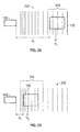
- Figures 2a and 2b illustrate operation of the sensor 106 in determining a magnitude of the magnetic field source 108 with respect to the sensor 106 and thus a relative position of first surface 102 to the second surface 104.
- the magnetic field source 108 produces magnetic field lines 202.
- the flux density of the magnetic field lines 202 varies along magnetic field source 108.
- Magnetic field strength is illustrated by relative densities of magnetic field lines 202 in Figures 2a and 2b .
- the sensor 106 generates a voltage that is proportional to a strength of a local magnetic field 204 (i.e., a magnetic field at the sensor 106).
- sensor 106 when the magnetic field source 108 at a first position (d 1 ; Figure 2a ) with respect to the sensor 106 and the local magnetic field 204 has a first magnetic field strength, sensor 106 generates a voltage at a first value (V 1 ) corresponding to the first magnetic field strength of the local magnetic field 204.
- V 1 first value
- the sensor 106 When the magnetic field source 108 and the sensor 106 are positioned to a second location (d 2 ; Figure 2b ) and the local magnetic field 204 has a second magnetic field strength, the sensor 106 generates a voltage at a second value (V 2 ) corresponding to the second magnetic field strength of the local magnetic field 204.
- voltage values V 1 and V 2 are different and may be used to determine the distance between the magnetic field source 108 and the sensor 106 and hence between the first surface 102 and the second surface 104.
- the sensor 106 Prior to being deployed, the sensor 106 may be calibrated to various sensor-source positions and magnetic field strengths. Thus, a selected voltage of the sensor 106 may correspond to a selected position between the first surface 102 and the second surface 104.
- the voltage (e.g., V 1 , V 2 ) generated by the sensor 106 is transmitted to a control unit 110.
- the control unit 110 includes a processor 112 and a memory 114 that may include any suitable non-transitory computer-readable medium such as a solid-state memory device, etc.
- the memory 114 may include programs 116 stored therein that enable the processor 112 to perform various instructions for determining a position between the first surface 102 and the second surface 104 and for controlling a position between the first surface 102 and the second surface 104.
- the processor 112 calculates the position of the first surface 102 relative to the second surface 104 from the voltage generated by sensor 106. In another embodiment, the processor 112 may control a position between the first surface 102 and the second surface 104. As an example, the processor 112 may select a relative position between the first surface 102 and the second surface 104 and determine an expected voltage that is generated by the sensor 106 when the first surface 102 and the second surface 104 are at the selected relative positions. The processor 112 may then send a signal to the actuator 120 to move the first surface 102 with respect to the second surface 104 and monitor the voltage generated by the sensor 106 while moving the first surface 102 with respect to the second surface 104.
- the processor 112 may determine a suitable action for the actuator 120.
- the actuator 120 may be controlled to continue motion when the first surface 102 and second surface 104 are approaching the selected relative position, reverse motion when the first surface 102 and second surface 104 are diverging from the selected relative distance or to cease motion when the generated voltage from the sensor 106 is within a selected criterion of the expected voltage (indicating that the first surface 102 and the second surface 104 are substantially at the selected relative distance).
- FIG. 3 shows an alternate embodiment of a flight surface control system in which a skew relation of the flight control surface may be determined and controlled.
- the flight surface control system 300 includes a first surface 302 including a plurality of sensors 306a, 306b, 306c and 306d disposed thereon.
- the apparatus 300 further includes a second surface 304 including at least one magnetic field source 308 disposed thereon.
- the plurality of sensors 306a-d generates voltages based on their relative position with respect to the at least one magnetic field source 308. The generated voltages may be used to determine a rotation or bending of the first surface 302 or other skew relation between the first surface 302 and the second surface 304.
- a plurality of actuators 310a, 310b, 310c and 310d are configured to move sections of the first surface 302 towards or away from corresponding sections of the second surface 304.
- a processor may receive the voltage signals from a selected sensors (e.g., sensor 306a) and determine a suitable action for a related actuator (e.g., actuator 310a) in order to correct for rotation of the first surface 302 or for a skew relation between the first surface 302 and the second surface 304, etc.
- a single magnetic field source 308 is shown in Figure 3 , a plurality of magnetic field sources may be used in alternate embodiments.
- each of the plurality of magnetic field sources may be disposed on the second surface 304 so that each magnetic field source corresponds directly with a respective sensor.
- Each sensor may thus respond to the magnetic field of its corresponding magnetic field source.
- Magnetic field shielding may be used to prevent a magnetic field from one of the plurality of magnetic field sources from being detected at a non-corresponding sensor.
- the at least one magnetic field source 308 may be disposed on the first surface 302 while the sensors 306a-d are disposed on the second surface 304.
- Figure 4 shows an illustrative aerodynamic surface 401 of an aircraft that includes a position sensor of the present disclosure.
- the aerodynamic surface 401 includes a guide track 403 that is attached or coupled to the aerodynamic surface 401.
- the guide track 403 may include a magnetic field source 405 disposed along its length.
- a sensor housing 407 is slidable along the guide track 403.
- the sensor housing 407 may include the sensor as well as various circuitry, such as a signal filter for filtering a signal from the sensor and an amplifier for amplifying a signal from the sensor.
- Figure 5 shows a side view of the illustrative aerodynamic surface 401.
- the sensor housing 407 is seen to be separated from the magnetic field source 405 by an air gap 501.
- the sensor housing further includes static support structure 503, such as an aircraft fuselage, etc., separated from the sensor housing by springs 505.
- the springs 505 may be used to control a width of the air gap 501 or separation between support structure 503 and aerodynamic surface 401.
- the sensor housing 407 may contain a single ratiometric Hall effect sensor or multiple Hall effect sensors. The use of multiple Hall effect sensors may be for the purpose of system redundancy.
- a motion of the aerodynamic surface 401 motion may be linear, angular or may have a complex kinematic motion defined by a multiple order polynomial.
- the guide track 403 and the magnetic field source 405 may be linear, angular or defined by a multiple order polynomial.
- the magnetic field source 405 may have a single magnetic pole along its length.
- the magnetic field source 405 may have multiple poles along its length.
- the magnetic flux of the magnetic field source 405 may be used to produce a signal related to a position of the sensor housing with respect to the aerodynamic surface 401.
- the signal may be give a relative position of the aerodynamic surface 401 with respect to the support structure 503.
- the signal gives a feedback of a discrete measurement of the relative position of the aerodynamic surface 401 and the support structure 503.
- Figure 6 shows a sensor output that corresponds with the sensor housing 407 moving along a guide track 403 that includes multiple poles along its length, as shown in the configuration 610.
- the sensor may pass from a region 602 of relatively high positive magnetic field density to a region 604 of relatively high negative magnetic field density.
- a voltage output from the sensor therefore corresponds to these magnetic field densities.
- the voltage output may be used to determine the position of the sensor housing 407 along the guide track 403.
- Figure 7 shows a sensor output that corresponds with a sensor housing 407 moving along a guide track 403 that includes a single pole along its length, as shown in the configuration 710.
- a region 702 of relatively high magnetic field density is surrounded on both sides by regions 704 and 706 of relatively low magnetic field density.
- the voltage output from the sensor may thus be used to determine the position of the sensor housing 407 along the guide track 403.
Landscapes
- Physics & Mathematics (AREA)
- General Physics & Mathematics (AREA)
- Engineering & Computer Science (AREA)
- Aviation & Aerospace Engineering (AREA)
- Measuring Magnetic Variables (AREA)
- Measurement Of Length, Angles, Or The Like Using Electric Or Magnetic Means (AREA)
Abstract
Description
- The present disclosure relates to flight control systems and, in particular, to a method and apparatus for determining a position of a flight control surface of an aircraft.
- An Aircraft utilizes a number of surfaces such as slats, flaps and horizontal stabilizers which are extended, retracted and rotated for aerodynamic control of the aircraft. Flight control systems integrate sensors for control surface position feedback. The position feedback sensors are typically electrically redundant linear variable differential transformers (LVDTs), resolvers or rotary variable differential transformers (RVDTs). Such flight control position feedback sensors tend to be bulky, providing additionally weight to the aircraft and requiring wings, etc. to be designed to accommodate these transformers and ancillary parts.
- According to one embodiment of the present disclosure, a method of determining a position of a first surface of an aircraft includes: disposing a sensor on one of the first surface and a second surface, wherein the first surface is moveable relative to the second surface; disposing a magnetic field source on the other of the first surface and the second surface to provide a discrete position of the first surface; detecting a local magnetic field at the sensor indicative of the relative position of the magnetic field source to the sensor; generating a voltage at the sensor indicative of the detected local magnetic field; and determining the discrete position of the first surface relative to the second surface from the generated electrical voltage.
- According to another embodiment of the present disclosure, an apparatus for controlling an aircraft includes: a first surface; a second surface movable relative to the first surface; a magnetic field source disposed on one of the first surface and the second surface; a sensor disposed on the other of the first surface and the second surface, the sensor configured to generate a voltage indicative of a magnetic field related to a distance between the sensor and the magnetic field source; and a processor configured to determine a relative distance between the first surface and the second surface from the generated voltage to control the aircraft.
- Additional features and advantages are realized through the techniques of the present disclosure. Other embodiments and aspects of the disclosure are described in detail herein and are considered a part of the claimed disclosure. For a better understanding of the disclosure with the advantages and the features, refer to the description and to the drawings.
- The subject matter which is regarded as the disclosure is particularly pointed out and distinctly claimed in the claims at the conclusion of the specification. The forgoing and other features, and advantages of the disclosure are apparent from the following detailed description taken in conjunction with the accompanying drawings in which:
-
Figure 1 shows an illustrative flight surface control system suitable for use in an aircraft in one embodiment of the present disclosure; -
Figures 2a and 2b illustrate operation of the sensor in determining a magnitude of the magnetic field source with respect to the sensor and thus a relative position of the first surface and second surface; -
Figure 3 shows an alternate embodiment of a flight surface control system in which a skew relation of the flight control surface may be determined and controlled; -
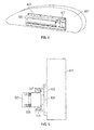
Figure 4 shows an illustrative aerodynamic surface of an aircraft that includes a position sensor of the present disclosure; -
Figure 5 shows a side view of the illustrative aerodynamic surface ofFigure 4 ; -
Figure 6 shows a sensor output that corresponds with the sensor housing moving along a guide track that includes multiple poles along its length, as shown in the configuration; and -
Figure 7 shows a sensor output that corresponds with a sensor housing moving along a guide track that includes a single pole along its length, as shown in the configuration. -
Figure 1 shows an illustrative flightsurface control system 100 suitable for use in an aircraft in one embodiment of the present disclosure. The flightsurface control system 100 includes afirst surface 102 and asecond surface 104. Thefirst surface 102 and thesecond surface 104 are moveable relative to each other by an actuator 120 (or actuator assembly) as indicated byarrow 122. In one embodiment, thefirst surface 102 may include a flight control surface of the aircraft and thesecond surface 104 may be a stationary surface of the aircraft that supports thefirst surface 102 at the aircraft. The flight control surface may include, for example, a horizontal stabilizer control surface, an aileron control surface, a rudder control surface, a trim tab control surface or any other surface that is used in the control of a flight of the aircraft. - The
first surface 102 includes asensor 106 disposed thereon that is sensitive to a magnetic field. In various embodiments, thesensor 106 may include a single ratiometric Hall effect sensor, multiple ratiometric Hall effect sensors, as well as an amplifier and/or a filter. Thesecond surface 104 includes amagnetic field source 108 disposed thereon which could have a single or multiple magnetic poles facing the sensor. Thesensor 106 and themagnetic field source 108 may be disposed facing each other so as to be in a direct line of sight of each other. This is shown inFigure 1 by thesensor 106 disposed on a lower face of the first surface 102 (indicated by dashed lines) and themagnetic field source 108 disposed on an upper face of thesecond surface 104 Magnetic shielding may be used to isolate thesensor 106 from magnetic field lines besides those provided by themagnetic field source 108. In various embodiments, themagnetic field source 108 may include a single magnet, a plurality of magnets, an electromagnet or electromagnetic assembly and/or a magnetic source capable of producing a shaped magnetic field. In alternate embodiments, thefirst surface 102 includes themagnetic field source 108 disposed thereon while thesecond surface 104 includes thesensor 106 disposed thereon. In either of these embodiments, motion of thefirst surface 102 relative to thesecond surface 104 produces a motion of themagnetic field source 108 relative to thesensor 106. -
Figures 2a and 2b illustrate operation of thesensor 106 in determining a magnitude of themagnetic field source 108 with respect to thesensor 106 and thus a relative position offirst surface 102 to thesecond surface 104. Themagnetic field source 108 producesmagnetic field lines 202. The flux density of themagnetic field lines 202 varies alongmagnetic field source 108. Magnetic field strength is illustrated by relative densities ofmagnetic field lines 202 inFigures 2a and 2b . Thesensor 106 generates a voltage that is proportional to a strength of a local magnetic field 204 (i.e., a magnetic field at the sensor 106). Therefore, when themagnetic field source 108 at a first position (d1;Figure 2a ) with respect to thesensor 106 and the localmagnetic field 204 has a first magnetic field strength,sensor 106 generates a voltage at a first value (V1) corresponding to the first magnetic field strength of the localmagnetic field 204. When themagnetic field source 108 and thesensor 106 are positioned to a second location (d2;Figure 2b ) and the localmagnetic field 204 has a second magnetic field strength, thesensor 106 generates a voltage at a second value (V2) corresponding to the second magnetic field strength of the localmagnetic field 204. Thus, voltage values V1 and V2 are different and may be used to determine the distance between themagnetic field source 108 and thesensor 106 and hence between thefirst surface 102 and thesecond surface 104. Prior to being deployed, thesensor 106 may be calibrated to various sensor-source positions and magnetic field strengths. Thus, a selected voltage of thesensor 106 may correspond to a selected position between thefirst surface 102 and thesecond surface 104. - Referring again to
Figure 1 , the voltage (e.g., V1, V2) generated by thesensor 106 is transmitted to acontrol unit 110. Thecontrol unit 110 includes aprocessor 112 and amemory 114 that may include any suitable non-transitory computer-readable medium such as a solid-state memory device, etc. Thememory 114 may includeprograms 116 stored therein that enable theprocessor 112 to perform various instructions for determining a position between thefirst surface 102 and thesecond surface 104 and for controlling a position between thefirst surface 102 and thesecond surface 104. - In one embodiment, the
processor 112 calculates the position of thefirst surface 102 relative to thesecond surface 104 from the voltage generated bysensor 106. In another embodiment, theprocessor 112 may control a position between thefirst surface 102 and thesecond surface 104. As an example, theprocessor 112 may select a relative position between thefirst surface 102 and thesecond surface 104 and determine an expected voltage that is generated by thesensor 106 when thefirst surface 102 and thesecond surface 104 are at the selected relative positions. Theprocessor 112 may then send a signal to theactuator 120 to move thefirst surface 102 with respect to thesecond surface 104 and monitor the voltage generated by thesensor 106 while moving thefirst surface 102 with respect to thesecond surface 104. By comparing the voltage generated by thesensor 106 with the expected voltage, theprocessor 112 may determine a suitable action for theactuator 120. For example, theactuator 120 may be controlled to continue motion when thefirst surface 102 andsecond surface 104 are approaching the selected relative position, reverse motion when thefirst surface 102 andsecond surface 104 are diverging from the selected relative distance or to cease motion when the generated voltage from thesensor 106 is within a selected criterion of the expected voltage (indicating that thefirst surface 102 and thesecond surface 104 are substantially at the selected relative distance). -
Figure 3 shows an alternate embodiment of a flight surface control system in which a skew relation of the flight control surface may be determined and controlled. The flightsurface control system 300 includes afirst surface 302 including a plurality ofsensors apparatus 300 further includes asecond surface 304 including at least onemagnetic field source 308 disposed thereon. The plurality ofsensors 306a-d generates voltages based on their relative position with respect to the at least onemagnetic field source 308. The generated voltages may be used to determine a rotation or bending of thefirst surface 302 or other skew relation between thefirst surface 302 and thesecond surface 304. A plurality ofactuators first surface 302 towards or away from corresponding sections of thesecond surface 304. A processor (not shown inFigure 3 ) may receive the voltage signals from a selected sensors (e.g.,sensor 306a) and determine a suitable action for a related actuator (e.g.,actuator 310a) in order to correct for rotation of thefirst surface 302 or for a skew relation between thefirst surface 302 and thesecond surface 304, etc. Although a singlemagnetic field source 308 is shown inFigure 3 , a plurality of magnetic field sources may be used in alternate embodiments. In particular, each of the plurality of magnetic field sources may be disposed on thesecond surface 304 so that each magnetic field source corresponds directly with a respective sensor. Each sensor may thus respond to the magnetic field of its corresponding magnetic field source. Magnetic field shielding may be used to prevent a magnetic field from one of the plurality of magnetic field sources from being detected at a non-corresponding sensor. In an alternate embodiment, the at least onemagnetic field source 308 may be disposed on thefirst surface 302 while thesensors 306a-d are disposed on thesecond surface 304. -
Figure 4 shows an illustrativeaerodynamic surface 401 of an aircraft that includes a position sensor of the present disclosure. Theaerodynamic surface 401 includes aguide track 403 that is attached or coupled to theaerodynamic surface 401. Theguide track 403 may include amagnetic field source 405 disposed along its length. Asensor housing 407 is slidable along theguide track 403. Thesensor housing 407 may include the sensor as well as various circuitry, such as a signal filter for filtering a signal from the sensor and an amplifier for amplifying a signal from the sensor. -
Figure 5 shows a side view of the illustrativeaerodynamic surface 401. Thesensor housing 407 is seen to be separated from themagnetic field source 405 by anair gap 501. The sensor housing further includesstatic support structure 503, such as an aircraft fuselage, etc., separated from the sensor housing bysprings 505. Thesprings 505 may be used to control a width of theair gap 501 or separation betweensupport structure 503 andaerodynamic surface 401. Thesensor housing 407 may contain a single ratiometric Hall effect sensor or multiple Hall effect sensors. The use of multiple Hall effect sensors may be for the purpose of system redundancy. A motion of theaerodynamic surface 401 motion may be linear, angular or may have a complex kinematic motion defined by a multiple order polynomial. Therefore, theguide track 403 and themagnetic field source 405 may be linear, angular or defined by a multiple order polynomial. In one embodiment, themagnetic field source 405 may have a single magnetic pole along its length. In an alternate embodiment, themagnetic field source 405 may have multiple poles along its length. As shown below inFigures 6 and 7 , the magnetic flux of themagnetic field source 405 may be used to produce a signal related to a position of the sensor housing with respect to theaerodynamic surface 401. Thus, the signal may be give a relative position of theaerodynamic surface 401 with respect to thesupport structure 503. In various embodiments, the signal gives a feedback of a discrete measurement of the relative position of theaerodynamic surface 401 and thesupport structure 503. -
Figure 6 shows a sensor output that corresponds with thesensor housing 407 moving along aguide track 403 that includes multiple poles along its length, as shown in theconfiguration 610. The sensor may pass from aregion 602 of relatively high positive magnetic field density to aregion 604 of relatively high negative magnetic field density. A voltage output from the sensor therefore corresponds to these magnetic field densities. The voltage output may be used to determine the position of thesensor housing 407 along theguide track 403. -
Figure 7 shows a sensor output that corresponds with asensor housing 407 moving along aguide track 403 that includes a single pole along its length, as shown in theconfiguration 710. Aregion 702 of relatively high magnetic field density is surrounded on both sides byregions sensor housing 407 along theguide track 403. - The terminology used herein is for the purpose of describing particular embodiments only and is not intended to be limiting of the disclosure. As used herein, the singular forms "a", "an" and "the" are intended to include the plural forms as well, unless the context clearly indicates otherwise. It will be further understood that the terms "comprises" and/or "comprising," when used in this specification, specify the presence of stated features, integers, steps, operations, elements, and/or components, but do not preclude the presence or addition of one more other features, integers, steps, operations, element components, and/or groups thereof. For the purposes of this disclosure, it is further understood that the terms "inboard" and "outboard" can be used interchangeably, unless context dictates otherwise.
- The corresponding structures, materials, acts, and equivalents of all means or step plus function elements in the claims below are intended to include any structure, material, or act for performing the function in combination with other claimed elements as specifically claimed. The description of the present disclosure has been presented for purposes of illustration and description. The embodiment was chosen and described in order to best explain the principles of the disclosure and the practical application, and to enable others of ordinary skill in the art to understand the disclosure for various embodiments with various modifications as are suited to the particular use contemplated.
- While the exemplary embodiment to the disclosure has been described, it will be understood by those skilled in the art that the scope of the invention is defined by the claims.
Claims (15)
- A method of determining a position of a first surface of an aircraft, comprising:disposing a sensor (106) on one of the first surface (102) and a second surface (104), wherein the first surface is moveable relative to the second surface;disposing a magnetic field source (108) on the other of the first surface and the second surface to provide a discrete position of the first surface;detecting a local magnetic field at the sensor indicative of the relative position of the magnetic field source to the sensor;generating a voltage at the sensor indicative of the detected local magnetic field; anddetermining the discrete position of the first surface relative to the second surface from the generated electrical voltage.
- The method of claim 1, wherein the sensor further comprises at least one of:(i) a ratiometric Hall-effect sensor; (ii) a sensor that generates a voltage corresponding to a strength of a local magnetic field; (iii) an amplifier of sensor output voltage; (iv) a filter of sensor output voltage; and (v) sensor housing with a spring loaded standoff for controlling an air gap between the sensor housing and the magnetic field source.
- The method of claim 1 or 2, wherein the magnetic field source further comprises at least one of: (i) a single magnet; (ii) multiple magnets; (iii) an electromagnetic assembly; (iv) a source producing a shaped magnetic field; (v) a magnetic field source having a single magnetic pole along its length; (vi) a magnetic field source having multiple magnetic poles along its length; and (vii) a guide track that is one of (a) linear, (b) angular and (c) defined by a multiple order polynomial.
- The method of claim 1, 2 or 3, further comprising controlling a relative distance between the first surface and the second surface based on the generated voltage.
- The method of claim 4, further comprising:determining an expected voltage of the sensor for a selected relative distance between the first surface and the second surface; andmoving the first surface and the second surface to the selected relative distance based on a comparison of the generated voltage of the sensor to the expected voltage.
- The method of any preceding claim, further comprising disposing a plurality of sensors on the one of the first surface and the second surface and determining a skew relation of the first surface with respect to the second surface from a plurality of electrical voltages generated by the plurality of sensors.
- The method of any preceding claim, wherein the first surface is one of a flight control surface and a stationary surface and the second surface is another of the flight control surface and a stationary surface.
- An apparatus for determining a position of a first surface of an aircraft, comprising:a second surface (104) movable relative to the first surface (102);a magnetic field source (108) disposed on one of the first surface and the second surface;a sensor (106) disposed on the other of the first surface and the second surface, the sensor configured to generate a voltage based on a local magnetic field indicative of a distance between the sensor and the magnetic field source; anda processor (112) configured to determine a relative distance between the first surface and the second surface from the generated voltage to control the aircraft.
- The apparatus of claim 8, wherein the sensor further comprises at least one of:(i) a ratiometric Hall-effect sensor; (ii) a sensor that generates a voltage corresponding to a strength of a local magnetic field; (iii) an amplifier of sensor output voltage; (iv) a filter of sensor output voltage; and (v) sensor housing with a spring loaded standoff for controlling an air gap between the sensor housing and the magnetic field source.
- The apparatus of claim 8 or 9, wherein the magnetic field source further comprises at least one of: (i) a single magnet; (ii) multiple magnets; (iii) an electromagnetic assembly; and (iv) a source producing a shaped magnetic field. (v) a magnetic field source having a single magnetic pole along its length; (vi) a magnetic field source having multiple magnetic poles along its length; and (vii) a guide track that is one of (a) linear, (b) angular and (c) defined by a multiple order polynomial.
- The apparatus of claim 8, 9 or 10, wherein the processor is further configured to control a relative distance between the first surface and the second surface based on the generated voltage.
- The apparatus of claim 11, wherein the processor is further configured to control the relative distance by:selecting a relative distance between the first surface and the second surface;determining an expected voltage of the sensor for the selected relative distance; andmoving the first surface and the second surface to the selected relative distance based on a comparison of the generated voltage from the sensor and the expected voltage.
- The apparatus of any of claims 8 to 12, wherein the sensor further comprises a plurality of sensors and the processor is further configured to determine a skew relation of the first surface and the second surface from a plurality of voltages generated by the plurality of sensors.
- The apparatus of any of claims 8 to 13, wherein the first surface is one of a flight control surface and a stationary surface and the second surface is another of the flight control surface and a stationary surface.
- The apparatus of claim 14, wherein the flight control surface is one of: (i) a horizontal stabilizer control surface; (ii) an aileron control surface; (iii) a rudder control surface; (iv) a trim tab control surface; (v) a high lift flap; (vi) a slat control surface; and (vii) a surface used in the control of a flight of the aircraft.
Applications Claiming Priority (1)
| Application Number | Priority Date | Filing Date | Title |
|---|---|---|---|
| US14/300,853 US10048090B2 (en) | 2014-06-10 | 2014-06-10 | Direct position measurement for aircraft flight control surfaces |
Publications (1)
| Publication Number | Publication Date |
|---|---|
| EP2955486A1 true EP2955486A1 (en) | 2015-12-16 |
Family
ID=53373305
Family Applications (1)
| Application Number | Title | Priority Date | Filing Date |
|---|---|---|---|
| EP15170776.7A Ceased EP2955486A1 (en) | 2014-06-10 | 2015-06-05 | Direct position measurement for aircraft flight control surfaces |
Country Status (2)
| Country | Link |
|---|---|
| US (1) | US10048090B2 (en) |
| EP (1) | EP2955486A1 (en) |
Families Citing this family (2)
| Publication number | Priority date | Publication date | Assignee | Title |
|---|---|---|---|---|
| US10235892B1 (en) * | 2017-05-05 | 2019-03-19 | Architecture Technology Corporation | Aircraft surface state event track system and method |
| US11479350B2 (en) * | 2020-06-19 | 2022-10-25 | Textron Innovations Inc. | Tip gap monitoring systems for ducted aircraft |
Citations (4)
| Publication number | Priority date | Publication date | Assignee | Title |
|---|---|---|---|---|
| US6295006B1 (en) * | 1999-04-16 | 2001-09-25 | Sikorsky Aircraft Corporation | Flap angle measurement system for an active rotor control system |
| DE102004047698A1 (en) * | 2004-09-30 | 2006-04-13 | Siemens Ag | position sensor |
| EP2392510A1 (en) * | 2010-06-04 | 2011-12-07 | Sonaca S.A. | Misalignment of bearing surfaces |
| US20140061369A1 (en) * | 2012-08-31 | 2014-03-06 | Bell Helicopter Textron Inc. | Rotor Position Determination System with Hall-Effect Sensors |
Family Cites Families (5)
| Publication number | Priority date | Publication date | Assignee | Title |
|---|---|---|---|---|
| AU2001241508A1 (en) * | 2000-02-17 | 2001-08-27 | Control Products, Inc. | Multi-turn, non-contacting rotary shaft position sensor |
| JP2002063682A (en) * | 2000-08-21 | 2002-02-28 | Nec Corp | Traveling position detector |
| DE10334869B3 (en) * | 2003-07-29 | 2004-09-16 | Tech3 E.K. | Rotation angle sensor has a rotating shaft with attached permanent magnets, with angular measurements based on both axial displacement of the shaft and sinusoidal and cosinusoidal signals generated by it |
| TW200630632A (en) * | 2004-10-11 | 2006-09-01 | Koninkl Philips Electronics Nv | Non-linear magnetic field sensors and current sensors |
| WO2007095308A2 (en) | 2006-02-13 | 2007-08-23 | The Johns Hopkins University | Compositions and methods to promote neural cell growth |
-
2014
- 2014-06-10 US US14/300,853 patent/US10048090B2/en active Active
-
2015
- 2015-06-05 EP EP15170776.7A patent/EP2955486A1/en not_active Ceased
Patent Citations (4)
| Publication number | Priority date | Publication date | Assignee | Title |
|---|---|---|---|---|
| US6295006B1 (en) * | 1999-04-16 | 2001-09-25 | Sikorsky Aircraft Corporation | Flap angle measurement system for an active rotor control system |
| DE102004047698A1 (en) * | 2004-09-30 | 2006-04-13 | Siemens Ag | position sensor |
| EP2392510A1 (en) * | 2010-06-04 | 2011-12-07 | Sonaca S.A. | Misalignment of bearing surfaces |
| US20140061369A1 (en) * | 2012-08-31 | 2014-03-06 | Bell Helicopter Textron Inc. | Rotor Position Determination System with Hall-Effect Sensors |
Also Published As
| Publication number | Publication date |
|---|---|
| US10048090B2 (en) | 2018-08-14 |
| US20160200450A1 (en) | 2016-07-14 |
Similar Documents
| Publication | Publication Date | Title |
|---|---|---|
| ES2720778T3 (en) | Redundant sum sum feedback actuator | |
| US8620522B2 (en) | Suppressing electrical failure effects in servo control systems | |
| CA2771422C (en) | Absolute position sensing | |
| US10780977B2 (en) | Aerodynamic control surface movement monitoring system | |
| ES2634558T3 (en) | Procedure for detecting a malfunction of a servo valve and a servo valve that applies this procedure | |
| EP3126226B1 (en) | System for detecting mechanical disconnect of a sensor from a controlled element | |
| US20160226349A1 (en) | Electromechanical linear actuator | |
| US20170122779A1 (en) | Angular position sensing device | |
| US10048090B2 (en) | Direct position measurement for aircraft flight control surfaces | |
| CN111669098A (en) | Method for controlling a long stator linear motor | |
| US10501201B2 (en) | Aerodynamic control surface movement monitoring system for aircraft | |
| US10267654B2 (en) | LVDT having a flexible element and a bobbin made of thermoplastic material | |
| EP2902749A1 (en) | Displacement sensor | |
| US20140365035A1 (en) | Air vehicle control system and method | |
| US10326398B2 (en) | Linear motor actuators | |
| CN102358205A (en) | Identification-based air-gap-free sensor electromagnetic attraction suspension control method | |
| JP2013007745A (en) | Induction sensor with datum adjustment | |
| EP3388792A1 (en) | Position detection systems and methods | |
| KR102232860B1 (en) | Air vehicle attitude control system and air vehicle attitude control method | |
| JP6221549B2 (en) | Magnetic device with contact detector and contact detection method for magnetic device | |
| US10113931B2 (en) | Probe measuring force adjuster | |
| EP3367070B1 (en) | Aircraft with a system for determining a position of a part | |
| US9611031B2 (en) | Flutter control actuator | |
| CN102255581A (en) | Method for controlling electromagnetic attractive force suspension without adopting gas gap sensor on basis of additional alternating voltage | |
| CA2855284A1 (en) | Flutter control actuator |
Legal Events
| Date | Code | Title | Description |
|---|---|---|---|
| PUAI | Public reference made under article 153(3) epc to a published international application that has entered the european phase |
Free format text: ORIGINAL CODE: 0009012 |
|
| AK | Designated contracting states |
Kind code of ref document: A1 Designated state(s): AL AT BE BG CH CY CZ DE DK EE ES FI FR GB GR HR HU IE IS IT LI LT LU LV MC MK MT NL NO PL PT RO RS SE SI SK SM TR |
|
| AX | Request for extension of the european patent |
Extension state: BA ME |
|
| RIN1 | Information on inventor provided before grant (corrected) |
Inventor name: BARGER, VICTOR |
|
| 17P | Request for examination filed |
Effective date: 20160616 |
|
| RBV | Designated contracting states (corrected) |
Designated state(s): AL AT BE BG CH CY CZ DE DK EE ES FI FR GB GR HR HU IE IS IT LI LT LU LV MC MK MT NL NO PL PT RO RS SE SI SK SM TR |
|
| 17Q | First examination report despatched |
Effective date: 20161014 |
|
| 18R | Application refused |
Effective date: 20171203 |