EP2955454B1 - Hvac systems and methods with refrigerant leak detection - Google Patents
Hvac systems and methods with refrigerant leak detection Download PDFInfo
- Publication number
- EP2955454B1 EP2955454B1 EP15169692.9A EP15169692A EP2955454B1 EP 2955454 B1 EP2955454 B1 EP 2955454B1 EP 15169692 A EP15169692 A EP 15169692A EP 2955454 B1 EP2955454 B1 EP 2955454B1
- Authority
- EP
- European Patent Office
- Prior art keywords
- blower
- flammable
- alert
- operational
- damper
- Prior art date
- Legal status (The legal status is an assumption and is not a legal conclusion. Google has not performed a legal analysis and makes no representation as to the accuracy of the status listed.)
- Active
Links
Images


Classifications
-
- F—MECHANICAL ENGINEERING; LIGHTING; HEATING; WEAPONS; BLASTING
- F24—HEATING; RANGES; VENTILATING
- F24F—AIR-CONDITIONING; AIR-HUMIDIFICATION; VENTILATION; USE OF AIR CURRENTS FOR SCREENING
- F24F11/00—Control or safety arrangements
- F24F11/30—Control or safety arrangements for purposes related to the operation of the system, e.g. for safety or monitoring
- F24F11/32—Responding to malfunctions or emergencies
- F24F11/36—Responding to malfunctions or emergencies to leakage of heat-exchange fluid
-
- F—MECHANICAL ENGINEERING; LIGHTING; HEATING; WEAPONS; BLASTING
- F24—HEATING; RANGES; VENTILATING
- F24F—AIR-CONDITIONING; AIR-HUMIDIFICATION; VENTILATION; USE OF AIR CURRENTS FOR SCREENING
- F24F11/00—Control or safety arrangements
- F24F11/30—Control or safety arrangements for purposes related to the operation of the system, e.g. for safety or monitoring
-
- F—MECHANICAL ENGINEERING; LIGHTING; HEATING; WEAPONS; BLASTING
- F24—HEATING; RANGES; VENTILATING
- F24F—AIR-CONDITIONING; AIR-HUMIDIFICATION; VENTILATION; USE OF AIR CURRENTS FOR SCREENING
- F24F11/00—Control or safety arrangements
- F24F11/30—Control or safety arrangements for purposes related to the operation of the system, e.g. for safety or monitoring
- F24F11/32—Responding to malfunctions or emergencies
- F24F11/33—Responding to malfunctions or emergencies to fire, excessive heat or smoke
-
- F—MECHANICAL ENGINEERING; LIGHTING; HEATING; WEAPONS; BLASTING
- F24—HEATING; RANGES; VENTILATING
- F24F—AIR-CONDITIONING; AIR-HUMIDIFICATION; VENTILATION; USE OF AIR CURRENTS FOR SCREENING
- F24F11/00—Control or safety arrangements
- F24F11/30—Control or safety arrangements for purposes related to the operation of the system, e.g. for safety or monitoring
- F24F11/32—Responding to malfunctions or emergencies
- F24F11/38—Failure diagnosis
-
- F—MECHANICAL ENGINEERING; LIGHTING; HEATING; WEAPONS; BLASTING
- F24—HEATING; RANGES; VENTILATING
- F24F—AIR-CONDITIONING; AIR-HUMIDIFICATION; VENTILATION; USE OF AIR CURRENTS FOR SCREENING
- F24F11/00—Control or safety arrangements
- F24F11/50—Control or safety arrangements characterised by user interfaces or communication
- F24F11/52—Indication arrangements, e.g. displays
-
- F—MECHANICAL ENGINEERING; LIGHTING; HEATING; WEAPONS; BLASTING
- F24—HEATING; RANGES; VENTILATING
- F24F—AIR-CONDITIONING; AIR-HUMIDIFICATION; VENTILATION; USE OF AIR CURRENTS FOR SCREENING
- F24F11/00—Control or safety arrangements
- F24F11/62—Control or safety arrangements characterised by the type of control or by internal processing, e.g. using fuzzy logic, adaptive control or estimation of values
-
- F—MECHANICAL ENGINEERING; LIGHTING; HEATING; WEAPONS; BLASTING
- F24—HEATING; RANGES; VENTILATING
- F24F—AIR-CONDITIONING; AIR-HUMIDIFICATION; VENTILATION; USE OF AIR CURRENTS FOR SCREENING
- F24F11/00—Control or safety arrangements
- F24F11/62—Control or safety arrangements characterised by the type of control or by internal processing, e.g. using fuzzy logic, adaptive control or estimation of values
- F24F11/63—Electronic processing
-
- F—MECHANICAL ENGINEERING; LIGHTING; HEATING; WEAPONS; BLASTING
- F24—HEATING; RANGES; VENTILATING
- F24F—AIR-CONDITIONING; AIR-HUMIDIFICATION; VENTILATION; USE OF AIR CURRENTS FOR SCREENING
- F24F11/00—Control or safety arrangements
- F24F11/70—Control systems characterised by their outputs; Constructional details thereof
- F24F11/72—Control systems characterised by their outputs; Constructional details thereof for controlling the supply of treated air, e.g. its pressure
- F24F11/74—Control systems characterised by their outputs; Constructional details thereof for controlling the supply of treated air, e.g. its pressure for controlling air flow rate or air velocity
- F24F11/77—Control systems characterised by their outputs; Constructional details thereof for controlling the supply of treated air, e.g. its pressure for controlling air flow rate or air velocity by controlling the speed of ventilators
-
- F—MECHANICAL ENGINEERING; LIGHTING; HEATING; WEAPONS; BLASTING
- F24—HEATING; RANGES; VENTILATING
- F24F—AIR-CONDITIONING; AIR-HUMIDIFICATION; VENTILATION; USE OF AIR CURRENTS FOR SCREENING
- F24F11/00—Control or safety arrangements
- F24F11/70—Control systems characterised by their outputs; Constructional details thereof
- F24F11/80—Control systems characterised by their outputs; Constructional details thereof for controlling the temperature of the supplied air
- F24F11/83—Control systems characterised by their outputs; Constructional details thereof for controlling the temperature of the supplied air by controlling the supply of heat-exchange fluids to heat-exchangers
-
- G—PHYSICS
- G01—MEASURING; TESTING
- G01M—TESTING STATIC OR DYNAMIC BALANCE OF MACHINES OR STRUCTURES; TESTING OF STRUCTURES OR APPARATUS, NOT OTHERWISE PROVIDED FOR
- G01M3/00—Investigating fluid-tightness of structures
- G01M3/02—Investigating fluid-tightness of structures by using fluid or vacuum
- G01M3/04—Investigating fluid-tightness of structures by using fluid or vacuum by detecting the presence of fluid at the leakage point
-
- F—MECHANICAL ENGINEERING; LIGHTING; HEATING; WEAPONS; BLASTING
- F24—HEATING; RANGES; VENTILATING
- F24F—AIR-CONDITIONING; AIR-HUMIDIFICATION; VENTILATION; USE OF AIR CURRENTS FOR SCREENING
- F24F11/00—Control or safety arrangements
- F24F11/70—Control systems characterised by their outputs; Constructional details thereof
- F24F11/80—Control systems characterised by their outputs; Constructional details thereof for controlling the temperature of the supplied air
- F24F11/86—Control systems characterised by their outputs; Constructional details thereof for controlling the temperature of the supplied air by controlling compressors within refrigeration or heat pump circuits
-
- F—MECHANICAL ENGINEERING; LIGHTING; HEATING; WEAPONS; BLASTING
- F24—HEATING; RANGES; VENTILATING
- F24F—AIR-CONDITIONING; AIR-HUMIDIFICATION; VENTILATION; USE OF AIR CURRENTS FOR SCREENING
- F24F2110/00—Control inputs relating to air properties
-
- F—MECHANICAL ENGINEERING; LIGHTING; HEATING; WEAPONS; BLASTING
- F25—REFRIGERATION OR COOLING; COMBINED HEATING AND REFRIGERATION SYSTEMS; HEAT PUMP SYSTEMS; MANUFACTURE OR STORAGE OF ICE; LIQUEFACTION SOLIDIFICATION OF GASES
- F25B—REFRIGERATION MACHINES, PLANTS OR SYSTEMS; COMBINED HEATING AND REFRIGERATION SYSTEMS; HEAT PUMP SYSTEMS
- F25B1/00—Compression machines, plants or systems with non-reversible cycle
-
- F—MECHANICAL ENGINEERING; LIGHTING; HEATING; WEAPONS; BLASTING
- F25—REFRIGERATION OR COOLING; COMBINED HEATING AND REFRIGERATION SYSTEMS; HEAT PUMP SYSTEMS; MANUFACTURE OR STORAGE OF ICE; LIQUEFACTION SOLIDIFICATION OF GASES
- F25B—REFRIGERATION MACHINES, PLANTS OR SYSTEMS; COMBINED HEATING AND REFRIGERATION SYSTEMS; HEAT PUMP SYSTEMS
- F25B2400/00—Component parts or details not otherwise provided for in this subclass
- F25B2400/12—Inflammable refrigerants
-
- Y—GENERAL TAGGING OF NEW TECHNOLOGICAL DEVELOPMENTS; GENERAL TAGGING OF CROSS-SECTIONAL TECHNOLOGIES SPANNING OVER SEVERAL SECTIONS OF THE IPC; TECHNICAL SUBJECTS COVERED BY FORMER USPC CROSS-REFERENCE ART COLLECTIONS [XRACs] AND DIGESTS
- Y02—TECHNOLOGIES OR APPLICATIONS FOR MITIGATION OR ADAPTATION AGAINST CLIMATE CHANGE
- Y02B—CLIMATE CHANGE MITIGATION TECHNOLOGIES RELATED TO BUILDINGS, e.g. HOUSING, HOUSE APPLIANCES OR RELATED END-USER APPLICATIONS
- Y02B30/00—Energy efficient heating, ventilation or air conditioning [HVAC]
- Y02B30/70—Efficient control or regulation technologies, e.g. for control of refrigerant flow, motor or heating
Definitions
- HVAC heating, ventilating and air conditioning or cooling
- HVAC Heating, ventilating, and air conditioning
- an air blower is used to pull air (i.e., return air) from the enclosed space into the HVAC system through ducts and push the air into the enclosed space through additional ducts after conditioning the air (e.g., heating, cooling or dehumidifying the air).
- air i.e., return air
- conditioning the air e.g., heating, cooling or dehumidifying the air.
- "or” does not require mutual exclusivity.
- Various types of HVAC systems may be used to provide conditioned air for enclosed spaces.
- the cooling aspect of the HVAC system utilizes a working fluid, or refrigerant, that cycles through various phases to realize cooling at a desired location.
- refrigerant a working fluid, or refrigerant
- refrigerants were selected that were in large measure non-toxic and non-flammable. These refrigerants were not, however, as desirable with respect to global warming potential.
- a push has been made to use refrigerants that have a low or lower global warming potential. Because such refrigerants are often at least mildly flammable, the refrigerant could pose a potential risk to the user in some situations.
- US6471136 shows a HVAC comprising a biosensor providing real time monitoring of a selected aspect of an air conditioning or a refrigeration process and system.
- HVAC heating, ventilating, and air conditioning
- the HVAC system 100 is for providing conditioned air to a first closed space 102, such as the interior of a building. At least a portion of the HVAC system 100 is disposed within a second closed space 104, or equipment space. The spaces may be defined by a plurality of walls 105. In this embodiment, a portion 106 of the system 100 is located within the building, i.e., within the second closed space 104, and a portion 108 outside the building.
- the HVAC system 100 includes an HVAC unit 110 that is disposed within the second closed space 104, or equipment space.
- the HVAC unit 110 includes a return air duct 112 that receives air 115 from the first closed space 102.
- the return air duct 112 may include or be coupled to a transition duct 114 that may include one or more filters 116.
- a blower 118 pulls the return air into the return air duct 112.
- the blower 118 is fluidly coupled to the return air duct 112.
- the blower 118 moves air into a conditioning compartment 120.
- the conditioning compartment 120 is fluidly coupled to the blower 118 for receiving air therefrom to be treated.
- the conditioning compartment 120 is formed with a plurality of compartment walls and formed with a sampling port 122 on one compartment wall.
- the conditioning compartment 120 may include a portion of a delivery duct 132 in some embodiments.
- the sampling port 122 is selectively covered by a damper 124 ( FIG. 2 ).
- the damper 124 is includes activation devices, e.g., motor or solenoid or other motive device, whereby a damper-control signal may be sent to the damper 124 to open or close the damper 124.
- the conditioning compartment 120 includes a heating device 126 and a cooling unit 128.
- the order of the heating device 126 and cooling unit 128 could be varied.
- the heating device 126 may be a furnace, hot water manifold, an electric heating element, or any source of heat. If the heating device 126 is a furnace it may include flue pipe 127.
- the heating device 126 is fluidly coupled to the conditioning compartment 120 for selectively heating air therein.
- the cooling unit 128 is fluidly coupled to the conditioning compartment 120 for selectively cooling air therein.
- the cooling unit 128 includes a flammable refrigerant, or working fluid.
- the cooling unit 128 may be an evaporator coil or device for receiving heat from the air flowing over the cooling unit.
- the cooling unit 128 includes at least one heat exchange surface.
- Flammable refrigerants include even mildly flammable refrigerants that if exposed to an ignition source under certain conditions could pose a risk of fire. Accordingly, leak detection is an issue of considerable interest and will be described further below.
- the flammable refrigerant may be, without limitation, any of the following: any A2L, A2, A3, B2, or B3 refrigerant; R1234YF by Honeywell and DuPont; methylene chloride (R30); methyl chloride (R40); ethane (R170); propane (R290); N-Butane (R600); isobutene (R-600A); methyl formate (R611); ammonia (R717); sulfur dioxide (R764); ethylene (R1150); hydrocarbon refrigerants; halo-hydrocarbon blends; difluoromethane (R-32); etc.
- the conditioning compartment 120 produces a treated air 130 that is delivered into the first closed space 102 by the delivery duct 132.
- the delivery duct 132 is fluidly coupled to the conditioning compartment 120 for discharging the treated air 130 from the conditioning compartment 120 into the first closed space 102.
- the processing unit 134 is associated with the HVAC unit 110.
- the processing unit 134 includes one or more processors 136 and one or more memories 138.
- the processing unit 134 may include an input 140 (e.g., touchpad, keyboard, etc.) and an output 142 (e.g., display).
- the processing unit 134 may be communicatively coupled (in communication through wires, wireless, or other means) with the blower 118, damper 124, or other devices to be monitored or controlled within the system 100.
- the one or more processors 136 are configured to execute one or more sequences of instructions, programming or code stored on or in the one or more memories 138, which includes all types of memory devices and includes readable medium used for storage.
- the processor 136 can be, for example, a general purpose microprocessor, a microcontroller, a digital signal processor, an application specific integrated circuit, a field programmable gate array, a programmable logic device, a controller, a state machine, a gated logic, discrete hardware components, an artificial neural network or any like suitable entity that can perform calculations or other manipulations of data.
- the memory 138 may include one or more the following: random access memory (RAM), flash memory, read only memory (ROM), programmable read only memory (PROM), erasable PROM, registers, hard disks, removable disks, CD-ROMS, DVDs, or any other suitable storage devices.
- RAM random access memory
- ROM read only memory
- PROM programmable read only memory
- PROM erasable PROM
- registers hard disks, removable disks, CD-ROMS, DVDs, or any other suitable storage devices.
- the cooling unit 128 is associated with a cooling subsystem 144.
- the cooling subsystem 144 is any system that is operational to develop a chilled working fluid for receiving heat within the cooling unit 128.
- the cooling subsystem 144 includes a closed-conduit pathway 145, or circuit.
- the flammable refrigerant is disposed within the closed conduit pathway 145.
- the closed-conduit pathway 145 includes a first refrigerant line 146 and a second refrigerant line 148.
- first and second refrigerant lines 146, 148 in this embodiment are disposed partially within the second closed space 104 and if they were to leak, could deliver the flammable refrigerant into the second closed space 104 and thereby pose a potential safety risk-particularly if a source of ignition is present.
- a risk may be posed by potential ignition sources, e.g., an open flame from a furnace. Additional spaces may need detectors, particularly if a refrigerant line in the space has a joint.
- the cooling subsystem 144 also includes a compressor 150 fluidly coupled to the closed-conduit pathway 145 for compressing the flammable refrigerant therein.
- a condenser 152 is fluidly coupled to the closed-conduit pathway 145 downstream of the compressor 150 for cooling the refrigerant.
- the condenser 152 may include on or more fans 154.
- An expansion device 156 is coupled to the closed-conduit pathway 145 downstream of the condenser 152 for decreasing a pressure of the refrigerant at the cooling unit 128.
- the cooling unit 128 includes a heat-exchange surface (not explicitly shown) and is fluidly coupled to the closed-conduit pathway 145 for receiving the flammable refrigerant.
- a control unit 158 may be disposed within the first closed space 102.
- the control unit 158 may include a thermostat for providing control signals to the blower 118, heating device 126, or cooling unit 128 (or cooling subsystem) in response to a temperature in the first closed space 102.
- the control unit 158 may include an input device and a display, such as a touch-screen display 160 and a speaker 162 for audible alerts or instructions.
- the control unit 158 is communicatively coupled, e.g., by wireless signal 164 or wired signal, to the processing unit 134. In some embodiments, the control unit 158 and the processing unit 134 may be the same unit.
- a flammable-component detector 166 is disposed within the second closed space 104 and positioned proximate the HVAC unit 110 such that any flammable refrigerant within the conditioned compartment 120 would flow through the sampling port 122 when the damper 124 ( Fig. 2 ) is open and onto the flammable-component detector 166.
- the flammable-component detector 166 is operable to produce a detection signal indicative of the level of the flammable component detected or a signal that a lower threshold has been reached.
- FIGURE 2 a portion of an HVAC system 100 is presented that is analogous most respects to that of FIGURE 1 .
- the HVAC unit 110 is shown disposed within the second closed space 104.
- the damper 124 covering sampling port 122 is shown.
- the damper 124 is communicatively coupled to a processing unit 134, such as a by a wireless connection or by wires 168.
- the processing unit 134 is communicatively coupled to the damper 124 for selectively providing a damper-control signal thereto to open and close the damper 124.
- the damper 124 includes an activation device to open or close the damper over the sampling port 122.
- a flammable-component detector 166 Located proximate to the sampling port 122 and damper 124 and preferably at a lower elevation is a flammable-component detector 166.
- the flammable-component detector 166 is communicatively coupled to the processing unit 134 by a wireless connection or by a wired connection 165 or other means.
- the processing unit 134 may be further communicatively coupled to the blower 118 to receive an operational-status signal from the blower 118. In some embodiments, the processing unit 134 is able to monitor operation of the blower 118 and provide control signals thereto to effect the operation of the blower 118.
- the flammable-component detector 166 is positioned so that if there is a leak of the flammable refrigerant within the conditioning compartment 120, when the sampling port 120 is in an open position, the refrigerant will pour from the sampling port 120 onto the flammable-component detector 166. In this way, the flammable-component detector 166 is able to monitor and detect a leak of refrigerant within the conditioning compartment 120 when the damper 124 is open and also monitor the second closed space 104 where the flammable-component detector 166 is positioned. It should be noted that when the blower (see 118 in FIG. 1 ) is operative, any refrigerant leak is diluted and therefore should pose no risk. When the blower is off, the damper 124 may be opened and potential leaks monitored.
- the response may include sending an alert signal to the control unit 158.
- the alert signal may be presented as a visual alert on the screen 160, an audible alert through speaker 162 ( FIG. 1 ), or other alert. This allows an active warning to the user in the first closed space 102 of the potential danger posed elsewhere, namely in the conditioning compartment 120 or second closed space 104.
- the responsive action may include closing the damper 124 and activating the blower 118 ( Fig. 1 ) or may include activating a ventilator 170.
- the ventilator 170 may be a fan that pulls air out of the second closed space 104 or moves air into the second closed space 104 for the purpose of diluting any leaked refrigerant.
- the ventilator 170 is communicatively coupled to the processing unit 134, e.g., by wireless or wired 172 connection or other means.
- the at least one processor 136 and at least one memory 138 are configured to perform the following steps: receive the operational-status signal from the blower 118; open the damper 124 when the operational-status signal from the blower indicates that the blower 118 is not operating; and close the damper 124 when the operational-status signal from the blower 118 indicates that the blower 118 is operating.
- the at least one processor 136 and at least one memory 138 may be further configured to monitor the detection signal from the flammable-component detector 166 and to send an alert when the detection signal is indicative a flammable component at least equal to an alert threshold.
- the alert may be an alert signal sent to the control unit 158 ( FIG.
- the processing unit 134 may prepare a blower-control signal to active the blower in response a detection signal indicative of a flammable component at or near an alert threshold. In another embodiment, the processing unit 134 also prepares a ventilation-activation signal that is sent to the ventilation blower 170 to assist with diluting any leaked refrigerant in the second closed space 104, or equipment space.
- the processing unit 134 may be configured to carryout numerous steps or functions within the system 100.
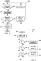
- FIGURE 3 the process 200 first considers whether the blower is on at interrogatory 202. If it is on, any refrigerant leak within the conditioning compartment 120 would be diluted and so the damper 124 is closed at step 204 to prevent air from entering the conditioning compartment 120. If the blower is not on, a leak could be an issue, and so the damper 124 is opened at step 206. In this way, the flammable-component detector 166 is effectively monitoring both the second closed space 104 and the conditioning compartment 120.
- the flammable-component detector 166 detects a level of one or more flammable components that exceeds an alert threshold, responsive action is taken. This question is considered at interrogatory 208. If the alert threshold is exceeded, responsive action is taken at step 210. The response may include sounding an audible alarm, presenting a visual alert, sending an email to the user or service provide or emergency personnel, activating the blower 118, activating a ventilator 170, etc. If the flammable-component detector 166 does not detect one or more flammable components exceeding an alert threshold, normal operation continues as shown as step 212 and the process returns to 202.
- the alert threshold may be set at a conservative percentage of a lower flammability limit.
- the alert threshold may be set at 25% of the lower flammability limit for the flammable refrigerant being used.
- the alert threshold may be 10, 20, 30, 40, or 50 % of the lower flammability limit.
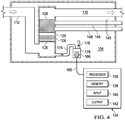
- FIGURE 4 a portion of an HVAC system 100 is shown.
- the HVAC system 100 of FIGURE 4 is analogous in most respects to the HVAC system of FIGURE 1 , and accordingly, some parts are labeled but not further described here.
- components referenced but not explicitly shown are analogous to those previously presented.
- a flammable-component detector 166 has a first probe 174 and a second probe 176 fluidly coupled to the detector 166.
- the first probe 174 is fluidly coupled to the flammable-component detector 166 and to the conditioning compartment 120.
- the second probe 176 is fluidly coupled to the flammable-component detector 166 and to the second closed space 104.
- This illustrative embodiment also includes a selector 178 for selectively providing fluid flow through the first probe 174 and for selectively providing fluid flow through the second probe 176 to the flammable-component detector 166.
- the selector 178 may be a plurality of valves, a plurality of sample blowers, or other devices.
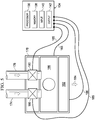
- first probe 174 and second probe 176 are shown in more detail with associated components in one illustrative embodiment.
- a plurality of valves 180 is shown.
- a sample blower 182 is shown that pulls fluid 184 through either open probe 174, 176 across the flammable-component detector 166.
- the plurality of valves 180 is controlled by the processing unit 134 and is shown communicatively coupled by wires 185 but of course it could be coupled by wireless or by other communication techniques.
- the sample blower 182 may be controlled by the processing unit 134 and is shown coupled by wire 186 but of course it could be coupled by wireless or by other communication techniques.
- valves are needed because of the flammable-component detector 166 is positioned at a location where any leaking refrigerant will run through the probe to the flammable-component detector 166.
- a sample blower 182 may be added to pull sample fluid past the flammable-component detector 166 and be used with valves 178, 180 or may be blowers individually associated with the probes 174, 176 and individually activated.
- the flammable-component detector 166 may, for example, be used for ten seconds with the first probe 174 and then for ten second with the second probe 176 and so forth. Other time intervals may be used. This approach allows one flammable-component detector 166 to monitor two spaces. It will be appreciated that this approach may be extended to a third space with a third probe and so on.
- the fluid delivered by each probe 174, 176 may be diluted by the fluid in the other, and accordingly the alert threshold may be set to account for the dilution. This is shown in an the illustrative process flow of FIGURE 6 .
- the processing unit 134 of FIGUREs 4-5 may be configured to carryout numerous steps or functions within the system 100.
- P the number of probes
- the process proceeds from interrogatory 306 to step 308, which sets the alert threshold at a normal limit (N), e.g., 25% lower flammability limit. If the answer to interrogatory 306 is negative, interrogatory 310, which asks if there are two probes, is considered. If there are two probes, at step 312, the alert threshold is set to 1 ⁇ 2 of normal limit (N), or base limit, e.g., 12.5% of the lower flammability limit (if the normal limit is 25% of the lower flammability limit).
- N normal limit
- base limit e.g., 12.5% of the lower flammability limit
- interrogatory 314 which asks if there are three probes, is reached. If affirmative, at step 316 the alert threshold is set to 1/3 of normal limit (N), e.g., 8.3 % lower flammability limit (if the normal limit is 25% of the lower flammability limit). This approach could continue as suggested by 318 to accommodate other numbers of probes.
- N normal limit
- the processing unit 134 considers samples from both probes 174, 176 and compares the results against each other. In this way, errors from calibration or drift may be cancelled out. If the difference between the two is greater than a difference threshold, an alert is triggered.
- an HVAC system for providing conditioned air to a first closed space, wherein at least a portion of the system is disposed within a second closed space, includes a cooling unit including a flammable refrigerant and at least one compartment wall separating the cooling unit from an equipment space.
- the at least one compartment wall is formed with an access port therethrough.
- the system further includes a controllable damper associated with the access port for selectively covering the access port and a flammable-component detector disposed within the equipment space proximate the access port, which is through the at least one compartment wall.
- the system also includes a processing unit communicatively coupled to the damper for opening and closing the damper.
- any use of any form of the terms “connect,” “engage,” “couple,” “attach,” or any other term describing an interaction between elements is not meant to limit the interaction to direct interaction between the elements and may also include indirect interaction between the elements described.
- Coupling includes in some instances communicatively coupled, which may be a wireless connection or a wired connection. Coupled in some instances may refer to fluid coupling.
- the terms “including” and “comprising” are used in an open-ended fashion, and thus should be interpreted to mean “including, but not limited to ... "
Landscapes
- Engineering & Computer Science (AREA)
- Chemical & Material Sciences (AREA)
- Combustion & Propulsion (AREA)
- Mechanical Engineering (AREA)
- General Engineering & Computer Science (AREA)
- Physics & Mathematics (AREA)
- Signal Processing (AREA)
- Fuzzy Systems (AREA)
- Mathematical Physics (AREA)
- General Physics & Mathematics (AREA)
- Fluid Mechanics (AREA)
- Human Computer Interaction (AREA)
- Health & Medical Sciences (AREA)
- Biomedical Technology (AREA)
- Air Conditioning Control Device (AREA)
- Examining Or Testing Airtightness (AREA)
Description
- This application is directed, in general, to heating, ventilating and air conditioning or cooling (HVAC) systems, and more specifically, to methods and systems with economical refrigerant leak detection.
- Heating, ventilating, and air conditioning (HVAC) systems can be used to regulate the environment within an enclosed space. Typically, an air blower is used to pull air (i.e., return air) from the enclosed space into the HVAC system through ducts and push the air into the enclosed space through additional ducts after conditioning the air (e.g., heating, cooling or dehumidifying the air). Unless otherwise indicated, as used throughout this document, "or" does not require mutual exclusivity. Various types of HVAC systems may be used to provide conditioned air for enclosed spaces.
- The cooling aspect of the HVAC system utilizes a working fluid, or refrigerant, that cycles through various phases to realize cooling at a desired location. In the past, refrigerants were selected that were in large measure non-toxic and non-flammable. These refrigerants were not, however, as desirable with respect to global warming potential. In more recent times, a push has been made to use refrigerants that have a low or lower global warming potential. Because such refrigerants are often at least mildly flammable, the refrigerant could pose a potential risk to the user in some situations.
-
US6471136 shows a HVAC comprising a biosensor providing real time monitoring of a selected aspect of an air conditioning or a refrigeration process and system. - Illustrative embodiments of the present invention are described in detail below with reference to the attached drawing figures, which are incorporated by reference herein and wherein:
-
FIGURE 1 is a schematic elevation view diagram of an HVAC system according to an illustrative embodiment; -
FIGURE 2 is a schematic plan view diagram of portion of an HVAC having a leak detector according to an illustrative embodiment; -
FIGURE 3 is an illustrative flow chart of an aspect of a method of detecting a refrigerant leak according to an illustrative embodiment; -
FIGURE 4 is a schematic plan view diagram of portion of an HVAC having a leak detector according to an illustrative embodiment; -
FIGURE 5 is a schematic diagram of portion of an HVAC having a leak detector according to an illustrative embodiment; and -
FIGURE 6 is an illustrative flow chart of an aspect of a method of detecting a refrigerant leak according to an illustrative embodiment. - In the following detailed description of the preferred embodiments, reference is made to the accompanying drawings that form a part hereof, and in which is shown, by way of illustration, specific embodiments in which the invention may be practiced. These embodiments are described in sufficient detail to enable those skilled in the art to practice the invention, and it is understood that other embodiments may be utilized and that logical structural, mechanical, electrical, and chemical changes may be made without departing from the spirit or scope of the invention. To avoid detail not necessary to enable those skilled in the art to practice the invention, the description may omit certain information known to those skilled in the art. The following detailed description is, therefore, not to be taken in a limiting sense, and the scope of the present invention is defined only by the claims.
- Referring now to the drawings and primarily to
FIGURE 1 , a heating, ventilating, and air conditioning (HVAC)system 100 is presented. TheHVAC system 100 is for providing conditioned air to a first closedspace 102, such as the interior of a building. At least a portion of theHVAC system 100 is disposed within a second closedspace 104, or equipment space. The spaces may be defined by a plurality ofwalls 105. In this embodiment, aportion 106 of thesystem 100 is located within the building, i.e., within the second closedspace 104, and aportion 108 outside the building. - The
HVAC system 100 includes anHVAC unit 110 that is disposed within the second closedspace 104, or equipment space. TheHVAC unit 110 includes areturn air duct 112 that receivesair 115 from the first closedspace 102. Thereturn air duct 112 may include or be coupled to atransition duct 114 that may include one ormore filters 116. Ablower 118 pulls the return air into thereturn air duct 112. Theblower 118 is fluidly coupled to thereturn air duct 112. Theblower 118 moves air into aconditioning compartment 120. - The
conditioning compartment 120 is fluidly coupled to theblower 118 for receiving air therefrom to be treated. Theconditioning compartment 120 is formed with a plurality of compartment walls and formed with asampling port 122 on one compartment wall. Theconditioning compartment 120 may include a portion of adelivery duct 132 in some embodiments. Thesampling port 122 is selectively covered by a damper 124 (FIG. 2 ). Thedamper 124 is includes activation devices, e.g., motor or solenoid or other motive device, whereby a damper-control signal may be sent to thedamper 124 to open or close thedamper 124. - The
conditioning compartment 120 includes aheating device 126 and acooling unit 128. The order of theheating device 126 andcooling unit 128 could be varied. Theheating device 126 may be a furnace, hot water manifold, an electric heating element, or any source of heat. If theheating device 126 is a furnace it may includeflue pipe 127. Theheating device 126 is fluidly coupled to theconditioning compartment 120 for selectively heating air therein. Thecooling unit 128 is fluidly coupled to theconditioning compartment 120 for selectively cooling air therein. Thecooling unit 128 includes a flammable refrigerant, or working fluid. Thecooling unit 128 may be an evaporator coil or device for receiving heat from the air flowing over the cooling unit. Thecooling unit 128 includes at least one heat exchange surface. - While the
system 100 will work with many refrigerants, thesystem 100 is primarily concerned with flammable refrigerants. Flammable refrigerants include even mildly flammable refrigerants that if exposed to an ignition source under certain conditions could pose a risk of fire. Accordingly, leak detection is an issue of considerable interest and will be described further below. The flammable refrigerant may be, without limitation, any of the following: any A2L, A2, A3, B2, or B3 refrigerant; R1234YF by Honeywell and DuPont; methylene chloride (R30); methyl chloride (R40); ethane (R170); propane (R290); N-Butane (R600); isobutene (R-600A); methyl formate (R611); ammonia (R717); sulfur dioxide (R764); ethylene (R1150); hydrocarbon refrigerants; halo-hydrocarbon blends; difluoromethane (R-32); etc. - Whether heated by
heating device 128 or cooled bycooling unit 128, theconditioning compartment 120 produces a treatedair 130 that is delivered into the first closedspace 102 by thedelivery duct 132. Thedelivery duct 132 is fluidly coupled to theconditioning compartment 120 for discharging the treatedair 130 from theconditioning compartment 120 into the first closedspace 102. - Referring additionally to
FIGURE 2 , theprocessing unit 134 is associated with theHVAC unit 110. Theprocessing unit 134 includes one ormore processors 136 and one ormore memories 138. Theprocessing unit 134 may include an input 140 (e.g., touchpad, keyboard, etc.) and an output 142 (e.g., display). Theprocessing unit 134 may be communicatively coupled (in communication through wires, wireless, or other means) with theblower 118,damper 124, or other devices to be monitored or controlled within thesystem 100. - The one or
more processors 136 are configured to execute one or more sequences of instructions, programming or code stored on or in the one ormore memories 138, which includes all types of memory devices and includes readable medium used for storage. Theprocessor 136 can be, for example, a general purpose microprocessor, a microcontroller, a digital signal processor, an application specific integrated circuit, a field programmable gate array, a programmable logic device, a controller, a state machine, a gated logic, discrete hardware components, an artificial neural network or any like suitable entity that can perform calculations or other manipulations of data. Thememory 138 may include one or more the following: random access memory (RAM), flash memory, read only memory (ROM), programmable read only memory (PROM), erasable PROM, registers, hard disks, removable disks, CD-ROMS, DVDs, or any other suitable storage devices. - The
cooling unit 128 is associated with acooling subsystem 144. Thecooling subsystem 144 is any system that is operational to develop a chilled working fluid for receiving heat within thecooling unit 128. In one embodiment, thecooling subsystem 144 includes a closed-conduit pathway 145, or circuit. The flammable refrigerant is disposed within theclosed conduit pathway 145. The closed-conduit pathway 145 includes a firstrefrigerant line 146 and a secondrefrigerant line 148. It will be appreciated that the first and secondrefrigerant lines closed space 104 and if they were to leak, could deliver the flammable refrigerant into the secondclosed space 104 and thereby pose a potential safety risk-particularly if a source of ignition is present. Similarly if the refrigerant leaks within thecooling unit 128 and therefor within theconditioning compartment 120, a risk may be posed by potential ignition sources, e.g., an open flame from a furnace. Additional spaces may need detectors, particularly if a refrigerant line in the space has a joint. - The
cooling subsystem 144 also includes acompressor 150 fluidly coupled to the closed-conduit pathway 145 for compressing the flammable refrigerant therein. Acondenser 152 is fluidly coupled to the closed-conduit pathway 145 downstream of thecompressor 150 for cooling the refrigerant. Thecondenser 152 may include on ormore fans 154. Anexpansion device 156 is coupled to the closed-conduit pathway 145 downstream of thecondenser 152 for decreasing a pressure of the refrigerant at thecooling unit 128. Thecooling unit 128 includes a heat-exchange surface (not explicitly shown) and is fluidly coupled to the closed-conduit pathway 145 for receiving the flammable refrigerant. - A
control unit 158 may be disposed within the firstclosed space 102. Thecontrol unit 158 may include a thermostat for providing control signals to theblower 118,heating device 126, or cooling unit 128 (or cooling subsystem) in response to a temperature in the firstclosed space 102. Thecontrol unit 158 may include an input device and a display, such as a touch-screen display 160 and aspeaker 162 for audible alerts or instructions. Thecontrol unit 158 is communicatively coupled, e.g., bywireless signal 164 or wired signal, to theprocessing unit 134. In some embodiments, thecontrol unit 158 and theprocessing unit 134 may be the same unit. - A flammable-
component detector 166 is disposed within the secondclosed space 104 and positioned proximate theHVAC unit 110 such that any flammable refrigerant within the conditionedcompartment 120 would flow through thesampling port 122 when the damper 124 (Fig. 2 ) is open and onto the flammable-component detector 166. The flammable-component detector 166 is operable to produce a detection signal indicative of the level of the flammable component detected or a signal that a lower threshold has been reached. - Referring now primarily to
FIGURE 2 , a portion of anHVAC system 100 is presented that is analogous most respects to that ofFIGURE 1 . TheHVAC unit 110 is shown disposed within the secondclosed space 104. In this figure, thedamper 124covering sampling port 122 is shown. Thedamper 124 is communicatively coupled to aprocessing unit 134, such as a by a wireless connection or bywires 168. Theprocessing unit 134 is communicatively coupled to thedamper 124 for selectively providing a damper-control signal thereto to open and close thedamper 124. Thedamper 124 includes an activation device to open or close the damper over thesampling port 122. Located proximate to thesampling port 122 anddamper 124 and preferably at a lower elevation is a flammable-component detector 166. The flammable-component detector 166 is communicatively coupled to theprocessing unit 134 by a wireless connection or by awired connection 165 or other means. - The
processing unit 134 may be further communicatively coupled to theblower 118 to receive an operational-status signal from theblower 118. In some embodiments, theprocessing unit 134 is able to monitor operation of theblower 118 and provide control signals thereto to effect the operation of theblower 118. - The flammable-
component detector 166 is positioned so that if there is a leak of the flammable refrigerant within theconditioning compartment 120, when thesampling port 120 is in an open position, the refrigerant will pour from thesampling port 120 onto the flammable-component detector 166. In this way, the flammable-component detector 166 is able to monitor and detect a leak of refrigerant within theconditioning compartment 120 when thedamper 124 is open and also monitor the secondclosed space 104 where the flammable-component detector 166 is positioned. It should be noted that when the blower (see 118 inFIG. 1 ) is operative, any refrigerant leak is diluted and therefore should pose no risk. When the blower is off, thedamper 124 may be opened and potential leaks monitored. - If the detection signal from the flammable-
component detector 166 that is delivered to theprocessing unit 134 exceeds an alert threshold, responsive action is taken. The response may include sending an alert signal to thecontrol unit 158. The alert signal may be presented as a visual alert on thescreen 160, an audible alert through speaker 162 (FIG. 1 ), or other alert. This allows an active warning to the user in the firstclosed space 102 of the potential danger posed elsewhere, namely in theconditioning compartment 120 or secondclosed space 104. - The responsive action may include closing the
damper 124 and activating the blower 118 (Fig. 1 ) or may include activating aventilator 170. Theventilator 170 may be a fan that pulls air out of the secondclosed space 104 or moves air into the secondclosed space 104 for the purpose of diluting any leaked refrigerant. Theventilator 170 is communicatively coupled to theprocessing unit 134, e.g., by wireless or wired 172 connection or other means. - In one illustrative embodiment, the at least one
processor 136 and at least onememory 138 are configured to perform the following steps: receive the operational-status signal from theblower 118; open thedamper 124 when the operational-status signal from the blower indicates that theblower 118 is not operating; and close thedamper 124 when the operational-status signal from theblower 118 indicates that theblower 118 is operating. The at least oneprocessor 136 and at least onememory 138 may be further configured to monitor the detection signal from the flammable-component detector 166 and to send an alert when the detection signal is indicative a flammable component at least equal to an alert threshold. The alert may be an alert signal sent to the control unit 158 (FIG. 1 ) present a visual or audible alert for the user in the firstclosed space 102. The user may have to select something to clear the alert. Theprocessing unit 134 may prepare a blower-control signal to active the blower in response a detection signal indicative of a flammable component at or near an alert threshold. In another embodiment, theprocessing unit 134 also prepares a ventilation-activation signal that is sent to theventilation blower 170 to assist with diluting any leaked refrigerant in the secondclosed space 104, or equipment space. - It will be appreciated that the
processing unit 134 may be configured to carryout numerous steps or functions within thesystem 100. As one example, reference is now made primarily toFIGURE 3 . In anillustrative process 200 inFIGURE 3 , theprocess 200 first considers whether the blower is on atinterrogatory 202. If it is on, any refrigerant leak within theconditioning compartment 120 would be diluted and so thedamper 124 is closed atstep 204 to prevent air from entering theconditioning compartment 120. If the blower is not on, a leak could be an issue, and so thedamper 124 is opened atstep 206. In this way, the flammable-component detector 166 is effectively monitoring both the secondclosed space 104 and theconditioning compartment 120. If the flammable-component detector 166 detects a level of one or more flammable components that exceeds an alert threshold, responsive action is taken. This question is considered atinterrogatory 208. If the alert threshold is exceeded, responsive action is taken atstep 210. The response may include sounding an audible alarm, presenting a visual alert, sending an email to the user or service provide or emergency personnel, activating theblower 118, activating aventilator 170, etc. If the flammable-component detector 166 does not detect one or more flammable components exceeding an alert threshold, normal operation continues as shown asstep 212 and the process returns to 202. - The alert threshold may be set at a conservative percentage of a lower flammability limit. For example, the alert threshold may be set at 25% of the lower flammability limit for the flammable refrigerant being used. Other safety margins-greater or lesser than 25%-may be used. For example, without limitation, the alert threshold may be 10, 20, 30, 40, or 50 % of the lower flammability limit.
- Referring now primarily to
FIGURE 4 , a portion of anHVAC system 100 is shown. TheHVAC system 100 ofFIGURE 4 is analogous in most respects to the HVAC system ofFIGURE 1 , and accordingly, some parts are labeled but not further described here. In addition, components referenced but not explicitly shown are analogous to those previously presented. In this embodiment, however, there is no sample port, but rather a flammable-component detector 166 has afirst probe 174 and asecond probe 176 fluidly coupled to thedetector 166. Thefirst probe 174 is fluidly coupled to the flammable-component detector 166 and to theconditioning compartment 120. Thesecond probe 176 is fluidly coupled to the flammable-component detector 166 and to the secondclosed space 104. This illustrative embodiment also includes aselector 178 for selectively providing fluid flow through thefirst probe 174 and for selectively providing fluid flow through thesecond probe 176 to the flammable-component detector 166. Theselector 178 may be a plurality of valves, a plurality of sample blowers, or other devices. - Referring now additionally to
FIGURE 5 , thefirst probe 174 andsecond probe 176 are shown in more detail with associated components in one illustrative embodiment. For illustration purposes, a plurality ofvalves 180 is shown. In addition asample blower 182 is shown that pulls fluid 184 through eitheropen probe component detector 166. The plurality ofvalves 180 is controlled by theprocessing unit 134 and is shown communicatively coupled bywires 185 but of course it could be coupled by wireless or by other communication techniques. Similarly, thesample blower 182 may be controlled by theprocessing unit 134 and is shown coupled bywire 186 but of course it could be coupled by wireless or by other communication techniques. - In some embodiments, only valves are needed because of the flammable-
component detector 166 is positioned at a location where any leaking refrigerant will run through the probe to the flammable-component detector 166. In some embodiments, asample blower 182 may be added to pull sample fluid past the flammable-component detector 166 and be used withvalves probes component detector 166 may, for example, be used for ten seconds with thefirst probe 174 and then for ten second with thesecond probe 176 and so forth. Other time intervals may be used. This approach allows one flammable-component detector 166 to monitor two spaces. It will be appreciated that this approach may be extended to a third space with a third probe and so on. - With respect to the monitoring of the flammable-
component detector 166 by the processing unit, it will be appreciated that the fluid delivered by eachprobe FIGURE 6 . - It will be appreciated that the
processing unit 134 ofFIGUREs 4-5 may be configured to carryout numerous steps or functions within thesystem 100. As one example, reference is now made primarily toFIGURE 6 . Theprocess 300 begins at 302 and at 304 the number of probes (P) is entered. For example, if the system ofFIGURE 5 were involved, two would be entered. If the number of probes were one, the process proceeds frominterrogatory 306 to step 308, which sets the alert threshold at a normal limit (N), e.g., 25% lower flammability limit. If the answer tointerrogatory 306 is negative, interrogatory 310, which asks if there are two probes, is considered. If there are two probes, atstep 312, the alert threshold is set to ½ of normal limit (N), or base limit, e.g., 12.5% of the lower flammability limit (if the normal limit is 25% of the lower flammability limit). - If the answer to
interrogatory 310 is negative, interrogatory 314, which asks if there are three probes, is reached. If affirmative, atstep 316 the alert threshold is set to 1/3 of normal limit (N), e.g., 8.3 % lower flammability limit (if the normal limit is 25% of the lower flammability limit). This approach could continue as suggested by 318 to accommodate other numbers of probes. - In one embodiment, the
processing unit 134 considers samples from bothprobes - According to an illustrative embodiment, an HVAC system for providing conditioned air to a first closed space is provided, wherein at least a portion of the system is disposed within a second closed space, includes a cooling unit including a flammable refrigerant and at least one compartment wall separating the cooling unit from an equipment space. The at least one compartment wall is formed with an access port therethrough. The system further includes a controllable damper associated with the access port for selectively covering the access port and a flammable-component detector disposed within the equipment space proximate the access port, which is through the at least one compartment wall. The system also includes a processing unit communicatively coupled to the damper for opening and closing the damper.
- Unless otherwise specified, any use of any form of the terms "connect," "engage," "couple," "attach," or any other term describing an interaction between elements is not meant to limit the interaction to direct interaction between the elements and may also include indirect interaction between the elements described. Coupling includes in some instances communicatively coupled, which may be a wireless connection or a wired connection. Coupled in some instances may refer to fluid coupling. In the discussion herein and in the claims, the terms "including" and "comprising" are used in an open-ended fashion, and thus should be interpreted to mean "including, but not limited to ... "
- It will be understood that the benefits and advantages described above may relate to one embodiment or may relate to several embodiments. It will further be understood that reference to "an" item refers to one or more of those items.
- The steps of the methods described herein may be carried out in any suitable order, or simultaneously where appropriate.
- Although the present invention and its advantages have been disclosed in the context of certain illustrative, non-limiting embodiments, it should be understood that various changes, substitutions, permutations, and alterations can be made without departing from the scope of the invention as defined by the claims. It will be appreciated that any feature that is described in a connection to any one embodiment may also be applicable to any other embodiment.
Claims (14)
- An HVAC system (100) for providing conditioned air to a first closed space (102), wherein at least a portion of the system is disposed within a second closed space (104), the system comprising:
an HVAC unit (110) comprising:a return air duct (112),a blower (118) fluidly coupled to the return air duct for pulling air through the return air duct,a conditioning compartment (120) fluidly coupled to the blower for receiving air therefrom to be treated, wherein the conditioning compartment is formed with a sampling port (122);a damper (124) for selectively covering and uncovering the sampling port in response to a damper-control signal;a cooling unit (128) fluidly coupled to the conditioning compartment for selectively cooling air therein, wherein the cooling unit comprises a flammable refrigerant, anda delivery duct (132) fluidly coupled to the conditioning compartment for discharging treated air from the conditioning compartment into the first closed space;a flammable-component detector (166) disposed within the second closed space and positioned proximate the HVAC unit such that any flammable refrigerant within the conditioning compartment would flow through the sampling port when the damper is open and onto the flammable-component detector, wherein the flammable-component detector is operable to produce a detection signal; anda processing unit (134) comprising at least one processor (136) and at least one memory (138), the processing unit communicatively coupled to the flammable-component detector for receiving the detection signal therefrom and coupled to the damper for selectively providing the damper-control signal. - The system (100) of claim 1, wherein the processing unit (134) is further communicatively coupled to the blower (118) to receive an operational-status signal from the blower (118), and wherein the at least one processor (136) and at least one memory (138) are configured to perform the following steps:receive the operational-status signal from the blower;open the damper (124) when the operational-status signal from the blower indicates that the blower is not operating; andclose the damper when the operational-status signal from the blower indicates that the blower is operating.
- The system (100) of claim 1, wherein the processing unit (134) is further communicatively coupled to the blower (118) to receive an operational-status signal from the blower, and wherein the at least one processor (136) and at least one memory (138) are configured to perform the following steps:receive an operational-status signal from the blower;open the damper (124) when the operational-status signal from the blower indicates that the blower is not operating;close the damper when the operational-status signal from the blower indicates that the blower is operating;monitor the detection signal from the flammable-component detector (166); andsend an alert when the detection signal is indicative of a flammable component at least equal to an alert threshold.
- The system (100) of claim 2 or claim 3, further comprising:a display (160) disposed within the first closed space (102), wherein the display is communicatively coupled to the processing unit (134); andwherein display is operable to receive the alert from the processing unit and provide a sensory alert.
- The system (100) of claim 2 or claim 3, further comprising:a display (160) disposed within the first closed space (102), wherein the display is communicatively coupled to the processing unit (134);wherein display is operable to receive the alert from the processing unit and provide a sensory alert, wherein the sensor alert is a visual alert.
- The system (100) of claim 2 or claim 3, further comprising:a display (160) disposed within the first closed space (102), wherein the display is communicatively coupled to the processing unit (134);wherein display is operable to receive the alert from the processing unit and provide a sensory alert, wherein the sensor alert is an audible alert.
- The system (100) of any preceding claim, wherein the processing unit (134) is further communicatively coupled to the blower (118) to receive an operational-status signal from the blower and to provide blower-control signal thereto, and wherein the at least one processor (136) and at least one memory (138) are configured to perform the following steps:receive an operational-status signal from the blower;open the damper (124) when the operational-status signal from the blower indicates that the blower is not operating;close the damper when the operational-status signal from the blower indicates that the blower is operating;monitor the detection signal from the flammable-component detector (166);send an alert when the detection signal is indicative a flammable component at least equal to an alert threshold; andsend the blower-control signal to active the blower in response a detection signal indicative of a flammable component at least equal to the alert threshold.
- The system (100) of any preceding claim, further comprising a ventilation blower (170) disposed within the second closed space (104) and communicatively coupled to the processing unit (134) for receiving a ventilation-activation signal and wherein the processing unit is further communicatively coupled to the blower (118) to receive an operational-status signal from the blower and to provide blower-control signal thereto, and wherein the at least one processor (136) and at least one memory (138) are configured to perform the following steps:receive an operational-status signal from the blower;open the damper (124) when the operational-status signal from the blower indicates that the blower is not operating;close the damper when the operational-status signal from the blower indicates that the blower is operating;monitor the detection signal from the flammable-component detector (166);send an alert when the detection signal is indicative a flammable component at least equal to an alert threshold; andsend the blower-control signal to activate the blower in response a detection signal indicative of a flammable component at least equal to the alert threshold and send the ventilation-activation signal to the ventilation blower (170).
- The system (100) of any preceding claim, further comprising a cooling subsystem (144), the cooling subsystem comprising:a closed-conduit pathway (145), wherein the flammable refrigerant is disposed within the closed conduit pathway;a compressor (150) fluidly coupled to the closed-conduit pathway for compressing the refrigerant;a condenser (152) fluidly coupled to the closed-conduit pathway downstream for the compressor for cooling the refrigerant;an expansion device (156) coupled to the closed-conduit pathway downstream of the condenser for decreasing a pressure of the refrigerant; andthe cooling unit (128) having a heat-exchange surface and fluidly coupled to the closed-conduit pathway for receiving the flammable refrigerant.
- The system (100) of any preceding claim, wherein the HVAC unit (110) further comprises a heating device (126) fluidly coupled to the conditioning compartment (120) for selectively heating air therein.
- The system (100) of claim 10, wherein the heating device (126) is a furnace.
- The system (100) of claim 10, wherein the heating device (126) is an electrical heating element.
- The system (100) of claim 1, the system further comprising:a first probe (174) fluidly coupled to the flammable-component detector (166) and to the conditioning compartment (120);a second probe (176) fluidly coupled to the flammable-component detector and to the second closed space (104);a selector (178) for selectively providing fluid flow in the first probe and for selectively providing fluid flow in the second probe; andthe at least one processor (136) and at least one memory (138) is operable to perform the following steps:monitor the detection signal, andsend an alert when the detection signal is indicative a flammable component at least equal to an alert threshold.
- The system (100) of claim 13:wherein the selector (178) is a plurality of control valves; and/orwherein the selector is a plurality of sample blowers, wherein a first sample blower of the plurality of sample blowers is associated with the first probe (174) and a second sample blower of the plurality of sample blowers is associated with the second probe (176); and/orwherein the alert threshold is one-half of a base threshold for a flammable-component detector (166) having only a single probe; and/orfurther comprising a third probe fluidly coupled to the flammable-component detector and to a third closed space, and wherein the alert threshold is one-third of a base threshold for a flammable-component detector having only a single probe; and/orwherein the HVAC unit (110) further comprises a heating device (126) fluidly coupled to the conditioning compartment (120) for selectively heating air therein.
Applications Claiming Priority (1)
| Application Number | Priority Date | Filing Date | Title |
|---|---|---|---|
| US14/304,871 US9879871B2 (en) | 2014-06-13 | 2014-06-13 | HVAC systems and methods with refrigerant leak detection |
Publications (3)
| Publication Number | Publication Date |
|---|---|
| EP2955454A2 EP2955454A2 (en) | 2015-12-16 |
| EP2955454A3 EP2955454A3 (en) | 2016-05-18 |
| EP2955454B1 true EP2955454B1 (en) | 2020-02-12 |
Family
ID=53385468
Family Applications (1)
| Application Number | Title | Priority Date | Filing Date |
|---|---|---|---|
| EP15169692.9A Active EP2955454B1 (en) | 2014-06-13 | 2015-05-28 | Hvac systems and methods with refrigerant leak detection |
Country Status (4)
| Country | Link |
|---|---|
| US (2) | US9879871B2 (en) |
| EP (1) | EP2955454B1 (en) |
| AU (2) | AU2015202605B2 (en) |
| CA (2) | CA2891059C (en) |
Families Citing this family (46)
| Publication number | Priority date | Publication date | Assignee | Title |
|---|---|---|---|---|
| US10119738B2 (en) | 2014-09-26 | 2018-11-06 | Waterfurnace International Inc. | Air conditioning system with vapor injection compressor |
| US10760839B2 (en) * | 2015-03-26 | 2020-09-01 | Mitsubishi Electric Corporation | Indoor unit of air-conditioning apparatus having leaked refrigerant ventilation |
| JP6135705B2 (en) * | 2015-04-06 | 2017-05-31 | ダイキン工業株式会社 | User side air conditioner |
| DE102015016330A1 (en) * | 2015-12-17 | 2017-06-22 | Eisenmann Se | Zuluftanlage |
| US20180321121A1 (en) * | 2016-01-19 | 2018-11-08 | Carrier Corporation | Sensor array for refrigerant detection |
| US9989960B2 (en) * | 2016-01-19 | 2018-06-05 | Honeywell International Inc. | Alerting system |
| AU2016404760B2 (en) * | 2016-04-28 | 2019-10-24 | Mitsubishi Electric Corporation | Refrigeration cycle apparatus |
| US10871314B2 (en) | 2016-07-08 | 2020-12-22 | Climate Master, Inc. | Heat pump and water heater |
| US10866002B2 (en) | 2016-11-09 | 2020-12-15 | Climate Master, Inc. | Hybrid heat pump with improved dehumidification |
| CN110312903A (en) * | 2017-02-24 | 2019-10-08 | 开利公司 | Methane security system for transport refrigeration unit |
| US11060775B2 (en) | 2017-03-09 | 2021-07-13 | Lennox Industries Inc. | Method and apparatus for refrigerant leak detection |
| EP4528174A3 (en) * | 2017-04-06 | 2025-06-11 | Carrier Corporation | Moderate-to-low global warming potential value refrigerant leak detection |
| JP6958127B2 (en) * | 2017-08-30 | 2021-11-02 | 株式会社富士通ゼネラル | Indoor unit of air conditioner |
| US10677679B2 (en) | 2017-12-01 | 2020-06-09 | Johnson Controls Technology Company | Refrigerant leak detection and management based on condensation from air samples |
| US10935454B2 (en) | 2017-12-01 | 2021-03-02 | Johnson Controls Technology Company | Systems and methods for refrigerant leak management |
| US10816247B2 (en) * | 2017-12-01 | 2020-10-27 | Johnson Controls Technology Company | Heating, ventilation, and air conditioning control system |
| SE543347C2 (en) | 2018-06-22 | 2020-12-08 | Flaektgroup Sweden Ab | A safety system, an air handling system, a method and a computer program product for evacuation of contaminated air |
| CN109114747B (en) * | 2018-08-03 | 2022-07-12 | 奥克斯空调股份有限公司 | Air conditioner fluorine deficiency detection method and system and air conditioner |
| US11592215B2 (en) | 2018-08-29 | 2023-02-28 | Waterfurnace International, Inc. | Integrated demand water heating using a capacity modulated heat pump with desuperheater |
| SG11202012167SA (en) | 2018-09-06 | 2021-03-30 | Carrier Corp | Refrigerant leak detection system |
| WO2020055685A1 (en) * | 2018-09-10 | 2020-03-19 | Carrier Corporation | Gas monitoring apparatus and method |
| JP2020051736A (en) * | 2018-09-28 | 2020-04-02 | ダイキン工業株式会社 | Heat load processing system |
| US11263062B2 (en) | 2019-02-06 | 2022-03-01 | Fujitsu Limited | API mashup exploration and recommendation |
| JP7076626B2 (en) * | 2019-03-04 | 2022-05-27 | 三菱電機株式会社 | Air conditioning system |
| JP7397275B2 (en) * | 2019-05-08 | 2023-12-13 | ダイキン工業株式会社 | air conditioning system |
| SG11202012779PA (en) * | 2019-05-17 | 2021-12-30 | Carrier Corp | Gas detector test and calibration method and apparatus |
| US11662109B2 (en) | 2019-06-05 | 2023-05-30 | Carrier Corporation | Enclosure for gas detector |
| EP3760955B1 (en) * | 2019-07-02 | 2024-09-18 | Carrier Corporation | Distributed hazard detection system for a transport refrigeration system |
| CA3081986A1 (en) | 2019-07-15 | 2021-01-15 | Climate Master, Inc. | Air conditioning system with capacity control and controlled hot water generation |
| US11231198B2 (en) | 2019-09-05 | 2022-01-25 | Trane International Inc. | Systems and methods for refrigerant leak detection in a climate control system |
| JP6978696B2 (en) * | 2019-09-30 | 2021-12-08 | ダイキン工業株式会社 | Air conditioning ventilation system |
| JP7157722B2 (en) * | 2019-09-30 | 2022-10-20 | ダイキン工業株式会社 | air conditioning ventilation system |
| FR3102237A1 (en) * | 2019-10-16 | 2021-04-23 | Systemair AC | Flammable gas evacuation device inside an air conditioner or heat pump |
| CN110715397B (en) * | 2019-10-18 | 2021-09-21 | 广东美的制冷设备有限公司 | Refrigerant leakage detection method and system of air conditioner and air conditioner |
| US11287153B2 (en) | 2019-12-02 | 2022-03-29 | Lennox Industries Inc. | Method and apparatus for risk reduction during refrigerant leak |
| CN111121222B (en) * | 2019-12-31 | 2021-11-09 | Tcl空调器(中山)有限公司 | Fluorine-lack protection method for air conditioner, air conditioner and readable storage medium |
| JP7439517B2 (en) * | 2020-01-07 | 2024-02-28 | 三菱電機株式会社 | Air blower and air blowing system |
| US11885516B2 (en) * | 2020-08-07 | 2024-01-30 | Copeland Lp | Refrigeration leak detection |
| JP7588297B2 (en) * | 2021-01-26 | 2024-11-22 | パナソニックIpマネジメント株式会社 | Air conditioners |
| CN113266921A (en) * | 2021-06-08 | 2021-08-17 | 深圳市英维克信息技术有限公司 | Air conditioning equipment fault detection method, device, equipment and medium |
| US12078368B2 (en) | 2021-06-11 | 2024-09-03 | Honeywell International Inc. | Apparatuses, systems, and methods for gas leak detection |
| US11781767B2 (en) * | 2021-06-11 | 2023-10-10 | Honeywell International Inc. | Apparatuses, systems, and methods for gas leak detection |
| US12181189B2 (en) | 2021-11-10 | 2024-12-31 | Climate Master, Inc. | Ceiling-mountable heat pump system |
| US12487008B2 (en) | 2022-01-14 | 2025-12-02 | Trane International Inc. | Method of commissioning an HVAC system |
| CN115031357B (en) * | 2022-05-10 | 2023-05-30 | 南京信息工程大学 | A Fault Diagnosis Method Based on Voting Strategy Applicable to Different Types of Fault Characteristics |
| US12117191B2 (en) | 2022-06-24 | 2024-10-15 | Trane International Inc. | Climate control system with improved leak detector |
Family Cites Families (20)
| Publication number | Priority date | Publication date | Assignee | Title |
|---|---|---|---|---|
| US3685577A (en) | 1971-07-30 | 1972-08-22 | Coleman Co | Mobile home air heating and cooling system |
| US4437868A (en) * | 1982-05-24 | 1984-03-20 | Kuhlman Ronald H | Controlled exhaust system for low temperature enclosure |
| JPS6452461A (en) * | 1988-05-19 | 1989-02-28 | Ueno Seiyaku Oyo Kenkyujo Kk | Condom |
| CA2376699C (en) | 1999-06-29 | 2004-09-21 | Carrier Corporation | Biosensors for monitoring air conditioning and refrigeration processes |
| JP3810960B2 (en) | 1999-09-07 | 2006-08-16 | 松下電器産業株式会社 | Ventilation system |
| WO2002027245A1 (en) | 2000-09-26 | 2002-04-04 | Daikin Industries, Ltd. | Air conditioner |
| US6609967B2 (en) * | 2000-12-11 | 2003-08-26 | Phoenix Controls Corporation | Methods and apparatus for recirculating air in a controlled ventilated environment |
| US20050086952A1 (en) | 2001-09-19 | 2005-04-28 | Hikaru Nonaka | Refrigerator-freezer controller of refrigenator-freezer, and method for determination of leakage of refrigerant |
| WO2003060400A1 (en) | 2002-01-15 | 2003-07-24 | Kabushiki Kaisha Toshiba | Refrigerator having alarm device for alarming leakage of refrigerant |
| JP2003322445A (en) | 2002-04-25 | 2003-11-14 | Matsushita Refrig Co Ltd | Manufacturing method of cooling storage |
| KR100471723B1 (en) | 2002-05-17 | 2005-03-08 | 삼성전자주식회사 | Air conditioner and control method thereof |
| US6796896B2 (en) * | 2002-09-19 | 2004-09-28 | Peter J. Laiti | Environmental control unit, and air handling systems and methods using same |
| JP2004169974A (en) * | 2002-11-19 | 2004-06-17 | Mitsubishi Electric Building Techno Service Co Ltd | Refrigerating installation |
| JP2006078090A (en) | 2004-09-09 | 2006-03-23 | Sanden Corp | Refrigeration unit |
| US20100035536A1 (en) | 2005-03-23 | 2010-02-11 | International Business Machines Corporation | Apparatus and method protecting against attack by particulate chemical or biological agents |
| JP4375437B2 (en) | 2007-05-28 | 2009-12-02 | 株式会社デンソー | Compressor suction pressure estimation device for refrigeration cycle equipment |
| JP5151378B2 (en) | 2007-10-10 | 2013-02-27 | パナソニック株式会社 | vending machine |
| US20120090383A1 (en) | 2010-10-14 | 2012-04-19 | Audra Lopez | System and method for detecting a refrigerant leak and chemicals produced as a result of heating of the refrigerant |
| US20130213068A1 (en) * | 2012-02-21 | 2013-08-22 | Rakesh Goel | Safe operation of space conditioning systems using flammable refrigerants |
| AU2013101100B4 (en) | 2013-08-17 | 2013-11-07 | Pioneer International Pty Ltd | An Arrangement and Method For Retrofitting an Air Conditioning System |
-
2014
- 2014-06-13 US US14/304,871 patent/US9879871B2/en active Active
-
2015
- 2015-05-12 CA CA2891059A patent/CA2891059C/en active Active
- 2015-05-12 CA CA3109486A patent/CA3109486C/en active Active
- 2015-05-14 AU AU2015202605A patent/AU2015202605B2/en not_active Ceased
- 2015-05-28 EP EP15169692.9A patent/EP2955454B1/en active Active
-
2017
- 2017-07-13 AU AU2017204857A patent/AU2017204857B2/en not_active Ceased
- 2017-12-21 US US15/851,731 patent/US10480807B2/en active Active
Non-Patent Citations (1)
| Title |
|---|
| None * |
Also Published As
| Publication number | Publication date |
|---|---|
| CA3109486C (en) | 2022-11-29 |
| US10480807B2 (en) | 2019-11-19 |
| EP2955454A3 (en) | 2016-05-18 |
| AU2017204857A1 (en) | 2017-08-03 |
| US20150362204A1 (en) | 2015-12-17 |
| US9879871B2 (en) | 2018-01-30 |
| CA3109486A1 (en) | 2015-12-13 |
| CA2891059A1 (en) | 2015-12-13 |
| AU2015202605B2 (en) | 2017-04-27 |
| EP2955454A2 (en) | 2015-12-16 |
| CA2891059C (en) | 2021-05-04 |
| AU2015202605A1 (en) | 2016-01-07 |
| US20180119977A1 (en) | 2018-05-03 |
| AU2017204857B2 (en) | 2019-04-04 |
Similar Documents
| Publication | Publication Date | Title |
|---|---|---|
| US10480807B2 (en) | HVAC systems and methods with refrigerant leak detection | |
| CA3072083C (en) | Hvac systems and methods with refrigerant purge | |
| EP4105573B1 (en) | Heating, ventilation, and air conditioning system, controller for such a system, and method of operation of such a system | |
| US20170052545A1 (en) | Gas monitoring and energy recycling system | |
| EP3633282B1 (en) | Air conditioning device | |
| US20180321121A1 (en) | Sensor array for refrigerant detection | |
| CA2879007C (en) | Systems and methods for refrigerant charge detection | |
| EP4163560B1 (en) | Frost remidiation and frost sensor | |
| US20220333806A1 (en) | Dual temperature sensor arrangement to detect refrigerant leak | |
| JP6498289B2 (en) | Refrigeration cycle system | |
| EP3296656A1 (en) | Air conditioning system, control method, and program | |
| EP3623716A1 (en) | Air conditioning system and refrigerant-amount setting method therefor | |
| CN109952479A (en) | Air conditioning units and air conditioning systems | |
| CN107477795A (en) | Combustible refrigerant air-conditioning and its control method | |
| EP3112768A1 (en) | Air conditioner | |
| CN105518396A (en) | Air conditioning system | |
| JP2002071188A (en) | Heat medium supply abnormality detection device | |
| JP6914794B2 (en) | Air conditioner | |
| KR20250027131A (en) | Air conditioner including detection sensor, and method for controlling the same | |
| TR201820586A2 (en) | A LEAK DETECTION SYSTEM |
Legal Events
| Date | Code | Title | Description |
|---|---|---|---|
| PUAI | Public reference made under article 153(3) epc to a published international application that has entered the european phase |
Free format text: ORIGINAL CODE: 0009012 |
|
| AK | Designated contracting states |
Kind code of ref document: A2 Designated state(s): AL AT BE BG CH CY CZ DE DK EE ES FI FR GB GR HR HU IE IS IT LI LT LU LV MC MK MT NL NO PL PT RO RS SE SI SK SM TR |
|
| AX | Request for extension of the european patent |
Extension state: BA ME |
|
| PUAL | Search report despatched |
Free format text: ORIGINAL CODE: 0009013 |
|
| AK | Designated contracting states |
Kind code of ref document: A3 Designated state(s): AL AT BE BG CH CY CZ DE DK EE ES FI FR GB GR HR HU IE IS IT LI LT LU LV MC MK MT NL NO PL PT RO RS SE SI SK SM TR |
|
| AX | Request for extension of the european patent |
Extension state: BA ME |
|
| RIC1 | Information provided on ipc code assigned before grant |
Ipc: G01M 3/04 20060101ALI20160408BHEP Ipc: F24F 11/00 20060101AFI20160408BHEP |
|
| STAA | Information on the status of an ep patent application or granted ep patent |
Free format text: STATUS: REQUEST FOR EXAMINATION WAS MADE |
|
| 17P | Request for examination filed |
Effective date: 20161117 |
|
| RBV | Designated contracting states (corrected) |
Designated state(s): AL AT BE BG CH CY CZ DE DK EE ES FI FR GB GR HR HU IE IS IT LI LT LU LV MC MK MT NL NO PL PT RO RS SE SI SK SM TR |
|
| RIC1 | Information provided on ipc code assigned before grant |
Ipc: F24F 11/00 20180101AFI20190717BHEP Ipc: G01M 3/04 20060101ALI20190717BHEP |
|
| GRAP | Despatch of communication of intention to grant a patent |
Free format text: ORIGINAL CODE: EPIDOSNIGR1 |
|
| STAA | Information on the status of an ep patent application or granted ep patent |
Free format text: STATUS: GRANT OF PATENT IS INTENDED |
|
| INTG | Intention to grant announced |
Effective date: 20190903 |
|
| RIN1 | Information on inventor provided before grant (corrected) |
Inventor name: OLSEN, MARK Inventor name: GOEL, RAKESH Inventor name: BOYD, HERMON ALAN |
|
| GRAS | Grant fee paid |
Free format text: ORIGINAL CODE: EPIDOSNIGR3 |
|
| GRAA | (expected) grant |
Free format text: ORIGINAL CODE: 0009210 |
|
| STAA | Information on the status of an ep patent application or granted ep patent |
Free format text: STATUS: THE PATENT HAS BEEN GRANTED |
|
| AK | Designated contracting states |
Kind code of ref document: B1 Designated state(s): AL AT BE BG CH CY CZ DE DK EE ES FI FR GB GR HR HU IE IS IT LI LT LU LV MC MK MT NL NO PL PT RO RS SE SI SK SM TR |
|
| REG | Reference to a national code |
Ref country code: GB Ref legal event code: FG4D |
|
| REG | Reference to a national code |
Ref country code: CH Ref legal event code: EP |
|
| REG | Reference to a national code |
Ref country code: AT Ref legal event code: REF Ref document number: 1232631 Country of ref document: AT Kind code of ref document: T Effective date: 20200215 |
|
| REG | Reference to a national code |
Ref country code: IE Ref legal event code: FG4D |
|
| REG | Reference to a national code |
Ref country code: DE Ref legal event code: R096 Ref document number: 602015046662 Country of ref document: DE |
|
| PG25 | Lapsed in a contracting state [announced via postgrant information from national office to epo] |
Ref country code: NO Free format text: LAPSE BECAUSE OF FAILURE TO SUBMIT A TRANSLATION OF THE DESCRIPTION OR TO PAY THE FEE WITHIN THE PRESCRIBED TIME-LIMIT Effective date: 20200512 Ref country code: FI Free format text: LAPSE BECAUSE OF FAILURE TO SUBMIT A TRANSLATION OF THE DESCRIPTION OR TO PAY THE FEE WITHIN THE PRESCRIBED TIME-LIMIT Effective date: 20200212 Ref country code: RS Free format text: LAPSE BECAUSE OF FAILURE TO SUBMIT A TRANSLATION OF THE DESCRIPTION OR TO PAY THE FEE WITHIN THE PRESCRIBED TIME-LIMIT Effective date: 20200212 |
|
| REG | Reference to a national code |
Ref country code: LT Ref legal event code: MG4D |
|
| REG | Reference to a national code |
Ref country code: NL Ref legal event code: MP Effective date: 20200212 |
|
| PG25 | Lapsed in a contracting state [announced via postgrant information from national office to epo] |
Ref country code: GR Free format text: LAPSE BECAUSE OF FAILURE TO SUBMIT A TRANSLATION OF THE DESCRIPTION OR TO PAY THE FEE WITHIN THE PRESCRIBED TIME-LIMIT Effective date: 20200513 Ref country code: IS Free format text: LAPSE BECAUSE OF FAILURE TO SUBMIT A TRANSLATION OF THE DESCRIPTION OR TO PAY THE FEE WITHIN THE PRESCRIBED TIME-LIMIT Effective date: 20200612 Ref country code: HR Free format text: LAPSE BECAUSE OF FAILURE TO SUBMIT A TRANSLATION OF THE DESCRIPTION OR TO PAY THE FEE WITHIN THE PRESCRIBED TIME-LIMIT Effective date: 20200212 Ref country code: SE Free format text: LAPSE BECAUSE OF FAILURE TO SUBMIT A TRANSLATION OF THE DESCRIPTION OR TO PAY THE FEE WITHIN THE PRESCRIBED TIME-LIMIT Effective date: 20200212 Ref country code: LV Free format text: LAPSE BECAUSE OF FAILURE TO SUBMIT A TRANSLATION OF THE DESCRIPTION OR TO PAY THE FEE WITHIN THE PRESCRIBED TIME-LIMIT Effective date: 20200212 Ref country code: BG Free format text: LAPSE BECAUSE OF FAILURE TO SUBMIT A TRANSLATION OF THE DESCRIPTION OR TO PAY THE FEE WITHIN THE PRESCRIBED TIME-LIMIT Effective date: 20200512 |
|
| PG25 | Lapsed in a contracting state [announced via postgrant information from national office to epo] |
Ref country code: NL Free format text: LAPSE BECAUSE OF FAILURE TO SUBMIT A TRANSLATION OF THE DESCRIPTION OR TO PAY THE FEE WITHIN THE PRESCRIBED TIME-LIMIT Effective date: 20200212 |
|
| PG25 | Lapsed in a contracting state [announced via postgrant information from national office to epo] |
Ref country code: ES Free format text: LAPSE BECAUSE OF FAILURE TO SUBMIT A TRANSLATION OF THE DESCRIPTION OR TO PAY THE FEE WITHIN THE PRESCRIBED TIME-LIMIT Effective date: 20200212 Ref country code: PT Free format text: LAPSE BECAUSE OF FAILURE TO SUBMIT A TRANSLATION OF THE DESCRIPTION OR TO PAY THE FEE WITHIN THE PRESCRIBED TIME-LIMIT Effective date: 20200705 Ref country code: DK Free format text: LAPSE BECAUSE OF FAILURE TO SUBMIT A TRANSLATION OF THE DESCRIPTION OR TO PAY THE FEE WITHIN THE PRESCRIBED TIME-LIMIT Effective date: 20200212 Ref country code: CZ Free format text: LAPSE BECAUSE OF FAILURE TO SUBMIT A TRANSLATION OF THE DESCRIPTION OR TO PAY THE FEE WITHIN THE PRESCRIBED TIME-LIMIT Effective date: 20200212 Ref country code: EE Free format text: LAPSE BECAUSE OF FAILURE TO SUBMIT A TRANSLATION OF THE DESCRIPTION OR TO PAY THE FEE WITHIN THE PRESCRIBED TIME-LIMIT Effective date: 20200212 Ref country code: LT Free format text: LAPSE BECAUSE OF FAILURE TO SUBMIT A TRANSLATION OF THE DESCRIPTION OR TO PAY THE FEE WITHIN THE PRESCRIBED TIME-LIMIT Effective date: 20200212 Ref country code: RO Free format text: LAPSE BECAUSE OF FAILURE TO SUBMIT A TRANSLATION OF THE DESCRIPTION OR TO PAY THE FEE WITHIN THE PRESCRIBED TIME-LIMIT Effective date: 20200212 Ref country code: SM Free format text: LAPSE BECAUSE OF FAILURE TO SUBMIT A TRANSLATION OF THE DESCRIPTION OR TO PAY THE FEE WITHIN THE PRESCRIBED TIME-LIMIT Effective date: 20200212 Ref country code: SK Free format text: LAPSE BECAUSE OF FAILURE TO SUBMIT A TRANSLATION OF THE DESCRIPTION OR TO PAY THE FEE WITHIN THE PRESCRIBED TIME-LIMIT Effective date: 20200212 |
|
| REG | Reference to a national code |
Ref country code: DE Ref legal event code: R097 Ref document number: 602015046662 Country of ref document: DE |
|
| REG | Reference to a national code |
Ref country code: AT Ref legal event code: MK05 Ref document number: 1232631 Country of ref document: AT Kind code of ref document: T Effective date: 20200212 |
|
| PLBE | No opposition filed within time limit |
Free format text: ORIGINAL CODE: 0009261 |
|
| STAA | Information on the status of an ep patent application or granted ep patent |
Free format text: STATUS: NO OPPOSITION FILED WITHIN TIME LIMIT |
|
| 26N | No opposition filed |
Effective date: 20201113 |
|
| PG25 | Lapsed in a contracting state [announced via postgrant information from national office to epo] |
Ref country code: CH Free format text: LAPSE BECAUSE OF NON-PAYMENT OF DUE FEES Effective date: 20200531 Ref country code: IT Free format text: LAPSE BECAUSE OF FAILURE TO SUBMIT A TRANSLATION OF THE DESCRIPTION OR TO PAY THE FEE WITHIN THE PRESCRIBED TIME-LIMIT Effective date: 20200212 Ref country code: MC Free format text: LAPSE BECAUSE OF FAILURE TO SUBMIT A TRANSLATION OF THE DESCRIPTION OR TO PAY THE FEE WITHIN THE PRESCRIBED TIME-LIMIT Effective date: 20200212 Ref country code: AT Free format text: LAPSE BECAUSE OF FAILURE TO SUBMIT A TRANSLATION OF THE DESCRIPTION OR TO PAY THE FEE WITHIN THE PRESCRIBED TIME-LIMIT Effective date: 20200212 Ref country code: LI Free format text: LAPSE BECAUSE OF NON-PAYMENT OF DUE FEES Effective date: 20200531 |
|
| PG25 | Lapsed in a contracting state [announced via postgrant information from national office to epo] |
Ref country code: PL Free format text: LAPSE BECAUSE OF FAILURE TO SUBMIT A TRANSLATION OF THE DESCRIPTION OR TO PAY THE FEE WITHIN THE PRESCRIBED TIME-LIMIT Effective date: 20200212 Ref country code: SI Free format text: LAPSE BECAUSE OF FAILURE TO SUBMIT A TRANSLATION OF THE DESCRIPTION OR TO PAY THE FEE WITHIN THE PRESCRIBED TIME-LIMIT Effective date: 20200212 |
|
| REG | Reference to a national code |
Ref country code: BE Ref legal event code: MM Effective date: 20200531 |
|
| PG25 | Lapsed in a contracting state [announced via postgrant information from national office to epo] |
Ref country code: LU Free format text: LAPSE BECAUSE OF NON-PAYMENT OF DUE FEES Effective date: 20200528 |
|
| PG25 | Lapsed in a contracting state [announced via postgrant information from national office to epo] |
Ref country code: IE Free format text: LAPSE BECAUSE OF NON-PAYMENT OF DUE FEES Effective date: 20200528 |
|
| PG25 | Lapsed in a contracting state [announced via postgrant information from national office to epo] |
Ref country code: BE Free format text: LAPSE BECAUSE OF NON-PAYMENT OF DUE FEES Effective date: 20200531 |
|
| PG25 | Lapsed in a contracting state [announced via postgrant information from national office to epo] |
Ref country code: TR Free format text: LAPSE BECAUSE OF FAILURE TO SUBMIT A TRANSLATION OF THE DESCRIPTION OR TO PAY THE FEE WITHIN THE PRESCRIBED TIME-LIMIT Effective date: 20200212 Ref country code: MT Free format text: LAPSE BECAUSE OF FAILURE TO SUBMIT A TRANSLATION OF THE DESCRIPTION OR TO PAY THE FEE WITHIN THE PRESCRIBED TIME-LIMIT Effective date: 20200212 Ref country code: CY Free format text: LAPSE BECAUSE OF FAILURE TO SUBMIT A TRANSLATION OF THE DESCRIPTION OR TO PAY THE FEE WITHIN THE PRESCRIBED TIME-LIMIT Effective date: 20200212 |
|
| PG25 | Lapsed in a contracting state [announced via postgrant information from national office to epo] |
Ref country code: MK Free format text: LAPSE BECAUSE OF FAILURE TO SUBMIT A TRANSLATION OF THE DESCRIPTION OR TO PAY THE FEE WITHIN THE PRESCRIBED TIME-LIMIT Effective date: 20200212 Ref country code: AL Free format text: LAPSE BECAUSE OF FAILURE TO SUBMIT A TRANSLATION OF THE DESCRIPTION OR TO PAY THE FEE WITHIN THE PRESCRIBED TIME-LIMIT Effective date: 20200212 |
|
| P01 | Opt-out of the competence of the unified patent court (upc) registered |
Effective date: 20230603 |
|
| P02 | Opt-out of the competence of the unified patent court (upc) changed |
Effective date: 20230619 |
|
| PGFP | Annual fee paid to national office [announced via postgrant information from national office to epo] |
Ref country code: DE Payment date: 20250529 Year of fee payment: 11 |
|
| PGFP | Annual fee paid to national office [announced via postgrant information from national office to epo] |
Ref country code: GB Payment date: 20250527 Year of fee payment: 11 |
|
| PGFP | Annual fee paid to national office [announced via postgrant information from national office to epo] |
Ref country code: FR Payment date: 20250526 Year of fee payment: 11 |