EP2955367A1 - An ignition system of a combustion engine - Google Patents
An ignition system of a combustion engine Download PDFInfo
- Publication number
- EP2955367A1 EP2955367A1 EP15169294.4A EP15169294A EP2955367A1 EP 2955367 A1 EP2955367 A1 EP 2955367A1 EP 15169294 A EP15169294 A EP 15169294A EP 2955367 A1 EP2955367 A1 EP 2955367A1
- Authority
- EP
- European Patent Office
- Prior art keywords
- ignition
- combustion engine
- ignition system
- cylinder
- engine
- Prior art date
- Legal status (The legal status is an assumption and is not a legal conclusion. Google has not performed a legal analysis and makes no representation as to the accuracy of the status listed.)
- Withdrawn
Links
- 238000002485 combustion reaction Methods 0.000 title claims abstract description 16
- 239000000203 mixture Substances 0.000 description 5
- 239000007789 gas Substances 0.000 description 2
- 230000006835 compression Effects 0.000 description 1
- 238000007906 compression Methods 0.000 description 1
- 230000002093 peripheral effect Effects 0.000 description 1
Images

Classifications
-
- F—MECHANICAL ENGINEERING; LIGHTING; HEATING; WEAPONS; BLASTING
- F02—COMBUSTION ENGINES; HOT-GAS OR COMBUSTION-PRODUCT ENGINE PLANTS
- F02P—IGNITION, OTHER THAN COMPRESSION IGNITION, FOR INTERNAL-COMBUSTION ENGINES; TESTING OF IGNITION TIMING IN COMPRESSION-IGNITION ENGINES
- F02P15/00—Electric spark ignition having characteristics not provided for in, or of interest apart from, groups F02P1/00 - F02P13/00 and combined with layout of ignition circuits
- F02P15/02—Arrangements having two or more sparking plugs
-
- F—MECHANICAL ENGINEERING; LIGHTING; HEATING; WEAPONS; BLASTING
- F02—COMBUSTION ENGINES; HOT-GAS OR COMBUSTION-PRODUCT ENGINE PLANTS
- F02B—INTERNAL-COMBUSTION PISTON ENGINES; COMBUSTION ENGINES IN GENERAL
- F02B23/00—Other engines characterised by special shape or construction of combustion chambers to improve operation
- F02B23/08—Other engines characterised by special shape or construction of combustion chambers to improve operation with positive ignition
- F02B2023/085—Other engines characterised by special shape or construction of combustion chambers to improve operation with positive ignition using several spark plugs per cylinder
-
- F—MECHANICAL ENGINEERING; LIGHTING; HEATING; WEAPONS; BLASTING
- F02—COMBUSTION ENGINES; HOT-GAS OR COMBUSTION-PRODUCT ENGINE PLANTS
- F02P—IGNITION, OTHER THAN COMPRESSION IGNITION, FOR INTERNAL-COMBUSTION ENGINES; TESTING OF IGNITION TIMING IN COMPRESSION-IGNITION ENGINES
- F02P15/00—Electric spark ignition having characteristics not provided for in, or of interest apart from, groups F02P1/00 - F02P13/00 and combined with layout of ignition circuits
- F02P15/08—Electric spark ignition having characteristics not provided for in, or of interest apart from, groups F02P1/00 - F02P13/00 and combined with layout of ignition circuits having multiple-spark ignition, i.e. ignition occurring simultaneously at different places in one engine cylinder or in two or more separate engine cylinders
Definitions
- the present invention relates to an ignition system of a combustion engine, designed to ignite the fuel-air mixture in its cylinder.
- ignition electrodes are mounted on a periphery of a combustion chamber in head cavities that are arranged around a cylinder of an engine block.
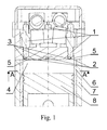
- An ignition system of an internal combustion engine has ignition elements 1 equipped with ignition electrodes 2, 3, which are mounted on a periphery of a combustion chamber 4 in cavities of a head 5. These cavities are arranged around a cylinder 6 of an engine block 7. A piston 8 is located in the cylinder.
- the operation of the ignition device of the internal combustion engine consists in that at the end of the compression stroke of the fuel-air mixture in the cylinder 6 by the piston 8, a spark-over between the ignition electrodes 2, 3 occurs at the same time. This causes the circumferential ignition of the fuel-air mixture and the movement of the flame from the periphery of the combustion chamber 4 and the cylinder 6 towards its axis in the direction of the piston 8.
- the advantage of the presented ignition system is a peripheral ignition of fuel-air mixture which causes orientation of the exhaust gas energy towards the centre of the cylinder, towards the piston's surface. This results in a uniform and rapid burning of the mixture within the volume of the combustion chamber, which results in a uniform impact of exhaust gases onto the surface of the piston.
- Another advantage is a reduction of wear of the cylinder wall by propagation of the combustion process toward the surface of the piston, as well as a reduction of the thermal load of the ignition elements by distributing the ignition to many ignition elements (by spreading the plurality of ignition plugs).
Landscapes
- Engineering & Computer Science (AREA)
- Chemical & Material Sciences (AREA)
- Combustion & Propulsion (AREA)
- Mechanical Engineering (AREA)
- General Engineering & Computer Science (AREA)
- Combustion Methods Of Internal-Combustion Engines (AREA)
- Ignition Installations For Internal Combustion Engines (AREA)
Abstract
An ignition system of an internal combustion engine comprising ignition electrodes positioned in a bottom part of the engine head, characterized in that the ignition electrodes (2, 3) are mounted on a periphery of a combustion chamber (4) in head cavities (5), which are arranged around a cylinder (6) of an engine block (7).
Description
- The present invention relates to an ignition system of a combustion engine, designed to ignite the fuel-air mixture in its cylinder.
- Ignition systems of a combustion engine, as disclosed herein, have not been described in professional publications so far.
- In the ignition system presented herein, ignition electrodes are mounted on a periphery of a combustion chamber in head cavities that are arranged around a cylinder of an engine block.
- Further details and features of the present invention, its nature and various advantages will become more apparent from the following detailed description of the preferred embodiments shown in a drawing, in which:
-
Fig. 1 shows a longitudinal section of an internal combustion engine, -
Fig. 2 shows an internal combustion engine in the section A-A ofFig. 1 . - An ignition system of an internal combustion engine has
ignition elements 1 equipped withignition electrodes combustion chamber 4 in cavities of ahead 5. These cavities are arranged around acylinder 6 of anengine block 7. Apiston 8 is located in the cylinder. - The operation of the ignition device of the internal combustion engine consists in that at the end of the compression stroke of the fuel-air mixture in the
cylinder 6 by thepiston 8, a spark-over between theignition electrodes combustion chamber 4 and thecylinder 6 towards its axis in the direction of thepiston 8. - The advantage of the presented ignition system is a peripheral ignition of fuel-air mixture which causes orientation of the exhaust gas energy towards the centre of the cylinder, towards the piston's surface. This results in a uniform and rapid burning of the mixture within the volume of the combustion chamber, which results in a uniform impact of exhaust gases onto the surface of the piston. Another advantage is a reduction of wear of the cylinder wall by propagation of the combustion process toward the surface of the piston, as well as a reduction of the thermal load of the ignition elements by distributing the ignition to many ignition elements (by spreading the plurality of ignition plugs).
Claims (1)
- An ignition system of an internal combustion engine comprising ignition electrodes positioned in a bottom part of the engine head, characterized in that the ignition electrodes (2, 3) are mounted on a periphery of a combustion chamber (4) in head cavities (5), which are arranged around a cylinder (6) of an engine block (7).
Applications Claiming Priority (1)
| Application Number | Priority Date | Filing Date | Title |
|---|---|---|---|
| PL408534A PL408534A1 (en) | 2014-06-12 | 2014-06-12 | Combustion engine ignition system |
Publications (1)
| Publication Number | Publication Date |
|---|---|
| EP2955367A1 true EP2955367A1 (en) | 2015-12-16 |
Family
ID=53365765
Family Applications (1)
| Application Number | Title | Priority Date | Filing Date |
|---|---|---|---|
| EP15169294.4A Withdrawn EP2955367A1 (en) | 2014-06-12 | 2015-05-27 | An ignition system of a combustion engine |
Country Status (2)
| Country | Link |
|---|---|
| EP (1) | EP2955367A1 (en) |
| PL (1) | PL408534A1 (en) |
Citations (8)
| Publication number | Priority date | Publication date | Assignee | Title |
|---|---|---|---|---|
| US2522921A (en) * | 1946-12-31 | 1950-09-19 | Jean A H Barkeij | Combustion chamber for internalcombustion engines |
| JPS56175518U (en) * | 1980-05-29 | 1981-12-24 | ||
| JPH02238176A (en) * | 1989-03-09 | 1990-09-20 | Mazda Motor Corp | Ignition device for engine |
| DE4229008A1 (en) * | 1991-08-30 | 1993-03-04 | Mazda Motor | Combustion engine ignition system with peripheral spark gaps - distributed uniformly around combustion chamber which has central spark gap for use only under heavier loading |
| JPH0559951A (en) * | 1991-09-02 | 1993-03-09 | Yamaha Motor Co Ltd | Combustion control device of engine |
| US5261367A (en) * | 1990-03-30 | 1993-11-16 | Mazda Motor Corporation | Engine and method for designing same |
| US5313921A (en) * | 1992-12-23 | 1994-05-24 | Feuling James J | High efficiency combustion chamber system |
| EP2202393A1 (en) * | 2007-10-22 | 2010-06-30 | Takagi Industrial Co., Ltd. | Multi-point ignition engine |
-
2014
- 2014-06-12 PL PL408534A patent/PL408534A1/en unknown
-
2015
- 2015-05-27 EP EP15169294.4A patent/EP2955367A1/en not_active Withdrawn
Patent Citations (8)
| Publication number | Priority date | Publication date | Assignee | Title |
|---|---|---|---|---|
| US2522921A (en) * | 1946-12-31 | 1950-09-19 | Jean A H Barkeij | Combustion chamber for internalcombustion engines |
| JPS56175518U (en) * | 1980-05-29 | 1981-12-24 | ||
| JPH02238176A (en) * | 1989-03-09 | 1990-09-20 | Mazda Motor Corp | Ignition device for engine |
| US5261367A (en) * | 1990-03-30 | 1993-11-16 | Mazda Motor Corporation | Engine and method for designing same |
| DE4229008A1 (en) * | 1991-08-30 | 1993-03-04 | Mazda Motor | Combustion engine ignition system with peripheral spark gaps - distributed uniformly around combustion chamber which has central spark gap for use only under heavier loading |
| JPH0559951A (en) * | 1991-09-02 | 1993-03-09 | Yamaha Motor Co Ltd | Combustion control device of engine |
| US5313921A (en) * | 1992-12-23 | 1994-05-24 | Feuling James J | High efficiency combustion chamber system |
| EP2202393A1 (en) * | 2007-10-22 | 2010-06-30 | Takagi Industrial Co., Ltd. | Multi-point ignition engine |
Also Published As
| Publication number | Publication date |
|---|---|
| PL408534A1 (en) | 2015-12-21 |
Similar Documents
| Publication | Publication Date | Title |
|---|---|---|
| EP1705371A3 (en) | Spark ignition engine, controller for use in the engine, ignition coil for use in the engine | |
| JP2016070270A5 (en) | ||
| KR101782574B1 (en) | Ignition plugs for internal combustion engine | |
| EP1777385A3 (en) | Internal combustion engine with auxiliary combustion chamber | |
| CN111219241B (en) | Internal combustion engine with auxiliary chamber | |
| US10145292B1 (en) | Spark plug | |
| US20160069251A1 (en) | Pressure-limiting device for pre-combustion chamber | |
| GB2491155B (en) | Opposed piston engine having injector located within cylinder | |
| WO2009091282A3 (en) | Internal combustion engine | |
| US20190195120A1 (en) | Internal combustion engine | |
| FI20145485A7 (en) | Zündvorrichtung zum Zünden eines Gasgemisches einer mit Gas betriebenen Brennkraftmaschine | |
| GB201122432D0 (en) | Internal combustion engines | |
| EP2955367A1 (en) | An ignition system of a combustion engine | |
| EP2053711A3 (en) | Spark plug | |
| RU2017102894A (en) | BURNING METHOD | |
| PH12018502663A1 (en) | Ignition device for internal combustion engine | |
| WO2013054188A3 (en) | Diesel engine combustion chamber, method for igniting a fuel-air mixture in a combustion chamber of a diesel engine and diesel engine | |
| WO2017102465A1 (en) | Spark plug | |
| JP7323008B2 (en) | internal combustion engine | |
| JP2015045252A5 (en) | ||
| RU83364U1 (en) | IGNITION CANDLE FOR INTERNAL COMBUSTION ENGINE | |
| WO2017135912A1 (en) | Improved piston | |
| JP2014529042A (en) | Combustion chamber of internal combustion engine, method for igniting fuel-air mixture, and internal combustion engine | |
| CN203119294U (en) | Spark plug and fire guide part thereof | |
| JP7081358B2 (en) | Internal combustion engine |
Legal Events
| Date | Code | Title | Description |
|---|---|---|---|
| PUAI | Public reference made under article 153(3) epc to a published international application that has entered the european phase |
Free format text: ORIGINAL CODE: 0009012 |
|
| AK | Designated contracting states |
Kind code of ref document: A1 Designated state(s): AL AT BE BG CH CY CZ DE DK EE ES FI FR GB GR HR HU IE IS IT LI LT LU LV MC MK MT NL NO PL PT RO RS SE SI SK SM TR |
|
| AX | Request for extension of the european patent |
Extension state: BA ME |
|
| STAA | Information on the status of an ep patent application or granted ep patent |
Free format text: STATUS: THE APPLICATION IS DEEMED TO BE WITHDRAWN |
|
| 18D | Application deemed to be withdrawn |
Effective date: 20160617 |