EP2955326A1 - Gas turbine airfoil with a grounding element - Google Patents
Gas turbine airfoil with a grounding element Download PDFInfo
- Publication number
- EP2955326A1 EP2955326A1 EP15171738.6A EP15171738A EP2955326A1 EP 2955326 A1 EP2955326 A1 EP 2955326A1 EP 15171738 A EP15171738 A EP 15171738A EP 2955326 A1 EP2955326 A1 EP 2955326A1
- Authority
- EP
- European Patent Office
- Prior art keywords
- platform
- airfoil
- grounding element
- sheath
- strip
- Prior art date
- Legal status (The legal status is an assumption and is not a legal conclusion. Google has not performed a legal analysis and makes no representation as to the accuracy of the status listed.)
- Granted
Links
Images


Classifications
-
- F—MECHANICAL ENGINEERING; LIGHTING; HEATING; WEAPONS; BLASTING
- F01—MACHINES OR ENGINES IN GENERAL; ENGINE PLANTS IN GENERAL; STEAM ENGINES
- F01D—NON-POSITIVE DISPLACEMENT MACHINES OR ENGINES, e.g. STEAM TURBINES
- F01D5/00—Blades; Blade-carrying members; Heating, heat-insulating, cooling or antivibration means on the blades or the members
- F01D5/12—Blades
- F01D5/14—Form or construction
- F01D5/147—Construction, i.e. structural features, e.g. of weight-saving hollow blades
-
- F—MECHANICAL ENGINEERING; LIGHTING; HEATING; WEAPONS; BLASTING
- F01—MACHINES OR ENGINES IN GENERAL; ENGINE PLANTS IN GENERAL; STEAM ENGINES
- F01D—NON-POSITIVE DISPLACEMENT MACHINES OR ENGINES, e.g. STEAM TURBINES
- F01D5/00—Blades; Blade-carrying members; Heating, heat-insulating, cooling or antivibration means on the blades or the members
- F01D5/12—Blades
- F01D5/28—Selecting particular materials; Particular measures relating thereto; Measures against erosion or corrosion
-
- F—MECHANICAL ENGINEERING; LIGHTING; HEATING; WEAPONS; BLASTING
- F01—MACHINES OR ENGINES IN GENERAL; ENGINE PLANTS IN GENERAL; STEAM ENGINES
- F01D—NON-POSITIVE DISPLACEMENT MACHINES OR ENGINES, e.g. STEAM TURBINES
- F01D5/00—Blades; Blade-carrying members; Heating, heat-insulating, cooling or antivibration means on the blades or the members
- F01D5/30—Fixing blades to rotors; Blade roots ; Blade spacers
- F01D5/3007—Fixing blades to rotors; Blade roots ; Blade spacers of axial insertion type
-
- F—MECHANICAL ENGINEERING; LIGHTING; HEATING; WEAPONS; BLASTING
- F02—COMBUSTION ENGINES; HOT-GAS OR COMBUSTION-PRODUCT ENGINE PLANTS
- F02C—GAS-TURBINE PLANTS; AIR INTAKES FOR JET-PROPULSION PLANTS; CONTROLLING FUEL SUPPLY IN AIR-BREATHING JET-PROPULSION PLANTS
- F02C3/00—Gas-turbine plants characterised by the use of combustion products as the working fluid
- F02C3/04—Gas-turbine plants characterised by the use of combustion products as the working fluid having a turbine driving a compressor
-
- F—MECHANICAL ENGINEERING; LIGHTING; HEATING; WEAPONS; BLASTING
- F05—INDEXING SCHEMES RELATING TO ENGINES OR PUMPS IN VARIOUS SUBCLASSES OF CLASSES F01-F04
- F05D—INDEXING SCHEME FOR ASPECTS RELATING TO NON-POSITIVE-DISPLACEMENT MACHINES OR ENGINES, GAS-TURBINES OR JET-PROPULSION PLANTS
- F05D2240/00—Components
- F05D2240/20—Rotors
- F05D2240/30—Characteristics of rotor blades, i.e. of any element transforming dynamic fluid energy to or from rotational energy and being attached to a rotor
- F05D2240/303—Characteristics of rotor blades, i.e. of any element transforming dynamic fluid energy to or from rotational energy and being attached to a rotor related to the leading edge of a rotor blade
Definitions
- the present disclosure relates generally to gas turbine engines and, more particularly, to airfoils in a gas turbine engine.
- Gas turbine engines may typically include a fan, a compressor, a combustor, and a turbine, with an annular flow path extending axially through each.
- the fan which is powered by the turbine, draws ambient air into the engine. Part of the air flows through the compressor where it is compressed or pressurized.
- the combustor then mixes and ignites the compressed air with fuel, generating hot combustion gases. These hot combustion gases are then directed from the combustor to the turbine where power is extracted from the hot gases by causing blades of the turbine to rotate. The other part of the airflow from the fan is used to generate forward thrust.
- fan blades Due to the large volume of air moving across the fan blades, static electric charge may build up. With fan blades composed of a conductive metal that was grounded to a hub, the static charge would dissipate. Recently, however, fan blades have been composed of aluminum in order to increase a size, but not a weight, of the blades. A titanium sheath may cover a leading edge of the fan blade, while a grounding element made of like material may be positioned on a platform and a root of the fan blade in order to from a ground path to dissipate the static charge buildup.
- an airfoil for a gas turbine engine may comprise a leading edge, a sheath on the leading edge; and a grounding element connected to the sheath.
- the grounding element may have a radially extending tab, and may be configured for connection to a component of the gas turbine engine to form a ground path from the sheath to the component.
- the airfoil may further comprise a collar overlapping the sheath and the tab of the grounding element.
- the tab may be preloaded toward the collar.
- the sheath may overlap the tab of the grounding element.
- the airfoil may further comprise a first side and an opposite second side extending radially outward from a platform to a tip; and a root extending radially inward from the platform, the grounding element being disposed on the platform and extending radially inward from the platform to the root, the tab projecting radially outward from the platform.
- the grounding element may include a platform cover disposed on a leading edge of the platform, and a strip extending from the platform cover to the root.
- the root may include a gradual bend from an under side of the platform to the root in order to enhance manufacturability of the strip.
- the strip may extend along a length of a leading edge of the root.
- the platform cover and the strip may comprise a multi-piece configuration.
- the platform cover may include a slot configured to receive an end of the strip.
- the platform may include a slot configured to receive an end of the strip.
- the grounding element may further include a dovetail cap extending from the strip and sized to cover a dovetail portion of a leading edge of the root.
- the dovetail portion of the leading edge of the root is shaped to fit within the dovetail cap.
- the platform cover, the strip, and the dovetail cap may comprise a three-piece configuration.
- the strip may include a multi-piece configuration including a first piece extending from the leading edge of the platform to an under side of the platform, and a second piece extending from the under side of the platform to the root.
- the platform cover may include a multi-piece configuration including a first piece extending circumferentially from a first side of the platform proximate to a centerline of the platform, and a second piece extending circumferentially proximate the centerline of the platform to a second side of the platform.
- an assembly for a gas turbine engine may comprise a fan section; a compressor section downstream of the fan section; a combustor section downstream of the compressor section; and a turbine section downstream of the combustor section.
- At least one of the fan section, the compressor section, and the turbine section may have an airfoil including a sheath disposed on a leading edge of the airfoil, and a grounding element disposed on a platform of the airfoil and extending radially inward from the platform to a root of the airfoil.
- the grounding element may include a tab projecting radially outward from the platform.
- the grounding element and the sheath may be connected to form a ground path from the sheath to a rotor in the at least one of the fan section, the compressor section, and the turbine section.
- a collar may connect the grounding element to the sheath.
- a method for increasing a connectivity between a sheath and a grounding element of an airfoil may comprise connecting the sheath of the airfoil to a tab on the grounding element of the airfoil, the tab projecting radially outward from a platform of the airfoil to a predetermined height along a side of the airfoil.
- the method may further comprise adhering the sheath on top of the tab.
- the gas turbine engine 20 may generally comprise a fan section 22 which draws ambient air into the engine 20, a compressor section 24 where air is pressurized, a combustor 26 downstream of the compressor section which mixes and ignites the compressed air with fuel and thereby generates hot combustion gases, a turbine section 28 downstream of the combustor 26 for extracting power from the hot combustion gases, and an annular flow path 30 extending axially through each.
- Gas turbine engine 20 may be used on an aircraft for generating thrust or power, or in land-based operations for generating power as well.
- the airfoil 40 may comprise a fan blade in the fan section 22, or a rotor blade or stator vane in the compressor section 24 or turbine section 28 of the gas turbine engine 20.
- Airfoil 40 may comprise a body 42 that includes a first side 44 and an opposite second side 46 projecting radially outward from a platform 48 to a tip 50.
- the first and second sides 44, 46 may extend axially from a leading edge 52 to a trailing edge 54 (downstream of the leading edge 52).
- the airfoil 40 may also include a root 56 extending from an under side 58 of the platform 48.
- the airfoil 40 may be installed or positioned within a rotor 60 of the engine 20.
- the root 56 may be shaped to fit within a groove 62 of the rotor 60.
- the body 42, platform 48, and root 56 of the airfoil 40 may be composed of aluminum or various aluminum alloys.
- protective coatings such as polyurethane and the like, may be applied to the airfoil 40.
- the airfoil 40 may be solid, hollow, or a combination thereof.
- the airfoil 40 may include channels, pockets, and filler materials (not shown).
- fabric wear pads 64 may be placed on the root 56 of the airfoil 40.
- a sheath 66 may be secured to the leading edge 52 of the body 42 of the airfoil 40.
- the sheath 66 may be bonded to the body 42, such as, via a conductive bonding agent or other adhesive.
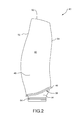
- the sheath 66 may cover the leading edge 52 proximate the platform 48 and extend to the tip 50 ( FIG. 2 ).
- the sheath 66 may strengthen the airfoil 40 against foreign object damage.
- the sheath 66 may be composed of titanium or various titanium alloys.
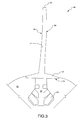
- the airfoil 40 may further include a grounding element 68 that provides a ground path from the sheath 66 to the rotor 60 ( FIG. 3 ) in order to dissipate static electric charge buildup.
- the grounding element 68 may be secured on the platform 48 and the root 56 of the airfoil 40, such as, via a conductive bonding agent or other adhesive. More specifically, the grounding element 68 may include a platform cover 70 and a strip 72.
- the platform cover 70 may extend over a leading edge 74 of the platform 48, and the strip 72 may extend from the platform cover 70 radially inward to the root 56 of the airfoil 40.
- the strip 72 may extend along the under side 58 of the platform 48 of the airfoil 40 to a leading edge 76 of the root 56.
- the grounding element 68 may be composed of a similar material as the sheath 66, such as, titanium or various titanium alloys.
- the grounding element 68 may include a tab 78 ( FIGS. 5-8 ) projecting radially outward from the platform cover 70.
- the tab 78 may extend along the first side 44 of the airfoil 40 to a predetermined height h ( FIG. 6 ).
- the predetermined height h may be approximately 0.5 inch (12.7 mm), although other heights are certainly possible.
- An example widthw ( FIG. 6 ) of the tab 78 may be approximately 0.5 inch (12.7 mm), although other widths are certainly possible.
- the tab 78 may also extend along the second side 46, leading edge 52, or around both sides 44, 46 and the leading edge 52 of the body 42 of the airfoil 40.
- the grounding element 68 may have more than one tab 78.
- a collar 80 may be secured around the sheath 66 and the grounding element 68 to ensure conductivity between the sheath 66 and the grounding element 68 and fortify the ground path.
- the collar 80 may overlap the tab 78, an edge 82 ( FIGS. 5-8 ) of the grounding element 68, and an end 84 ( FIGS. 5 and 6 ) of the sheath 66.
- the collar 80 may be bonded to the grounding element 68 (e.g., to the tab 78 and edge 82), sheath 66, and body 42 of the airfoil 40 via a conductive bonding agent or other adhesive.
- the tab 78 of the grounding element 68 may be preloaded or biased toward the collar 80 to enhance contact and ensure conductivity between components.
- the tab 78 may be over-bent or bent towards the collar 80 in a forming process.
- the tab 78 may not be bonded to the body 42 of the airfoil 40 to allow a spring effect with the collar 80. However, if desired, it is certainly possible to bond the tab 78 to the body 42.
- the collar 80 may be composed of a similar material as the sheath 66 and the grounding element 68, such as, titanium or various titanium alloys.
- the collar may have a height of approximately 0.75 inch (19.05 mm), although other heights are certainly possible.
- each of the sheath 66, grounding element 68, and collar 80 may have an approximate thickness within an inclusive range of 0.025 inch (0.635 mm) to 0.030 inch (0.762 mm), although other thicknesses are certainly possible.
- the grounding element 68 may be made through a serious of various processes.
- a piece of sheet metal 86 FIG. 11
- Other processes such as, die forming or hydroforming, may certainly be used.
- a pattern 88 ( FIG. 12 ) of the grounding element 68 may be cut from the piece of bent sheet metal 86, such as, via a five axis laser or other cutting method.
- the cut pattern 88 may then go through hot forming (or other processes) in order to mold the grounding element 68 into a shape that fits around the airfoil 40 and provides for strong adhesion between the grounding element 68 and airfoil 40. More specifically, the edge 82 ( FIGS. 5-8 ) and the tab 78 may be bent or formed to a contour of the body 42 of the airfoil 40, and the strip 72 may be bent or formed to a contour of the under side 58 of the platform 48 and the root 56 of the airfoil 40. The sheath 66 and the collar 80 may be formed via similar processes as the grounding element 68.
- the root 56 of the airfoil 40 may be configured to enhance manufacturability of the grounding element 68.
- the root 56 may include a gradual bend 90 from the under side 58 of the platform 48 to the leading edge 76 of the root 56.
- the strip 72 does not have to be bent in an acute angle in order to conform with a contour of the airfoil 40, thereby enabling an ease of manufacturability of the strip 72 and adhesion to the bend 90 on the under side 58 of the platform 48.
- the grounding element 68 may comprise a multi-piece configuration.
- the platform cover 70 and the strip 72 may be two separate pieces, as opposed to the platform cover 70 and the strip 72 being integrated into one piece.
- the platform cover 70 may include a slot 92 configured to receive an end 94 of the strip 72.
- the strip 72 may extend proximate to a bottom 96 of the leading edge 76 of the root 56 and may be substantially rectangular in shape, although other shapes are certainly possible.
- a bending of the strip 72 during manufacture to match an angle of the underside 58 of the platform 48 and the leading edge 76 of the root 56 may be less difficult. There may also be improved sealing and alignment when the parts are assembled, thereby eliminating tolerance issues and minimizing galvanic corrosion.
- the grounding element 68 may also include a dovetail cap 98.
- the dovetail cap 98 may be a separate piece from the platform cover 70 and the strip 72 and may be sized to cover a dovetail portion 100 of the leading edge 76 of the root 56.
- the dovetail portion 100 of the leading edge 76 of the root 56 may be shaped to fit within the dovetail cap 98.
- the dovetail portion 100 of the leading edge 76 may be machined such that it has a reduced volume than a rest 102 of the root 56, and the dovetail cap 98 ( FIGS. 16-18 ) may be attached without adding extra weight or volume to the airfoil 40.
- the dovetail cap 98 may be secured to the dovetail portion 100 of the leading edge 76 of the root 56, such as, via a conductive bonding agent or other adhesive.
- the strip 72 may be bonded over the dovetail cap 98 and may not extend proximate to the bottom 96 of the root 56.
- the dovetail cap 98 may be composed of a similar material as the sheath 66, platform cover 70, and strip 72, such as, titanium or various titanium allows.
- the dovetail cap 98 may be formed via hot forming or other suitable processes.
- the dovetail cap 98 By including the dovetail cap 98, there may be a greater bonding area for the grounding element 68, and therefore, a stronger bond to the airfoil 40. In so doing, there may be improved sealing and assembly, thereby minimizing galvanic corrosion.
- the strip 72 and dovetail cap 98 may be one integral piece.
- a strip 104 of the grounding element 68 may have an integrated dovetail cap portion 106.
- the leading edge 74 of the platform 48 may include a slot 108 configured to receive the end 94 of the strip 72.
- the strip 72 may be embedded and secured within the slot 108 on the airfoil 40. In so doing, a forward protrusion of the platform cover 70 of the grounding element 68 may be eliminated when a multi-piece configuration is used for the platform cover 70 and the strip 72.
- a sheath 110 may be directly connected to and extend over the grounding element 68.
- an end 112 of the sheath 110 may overlap and be secured to the tab 78 and the edge 82 of the grounding element 68.
- the sheath 110 may include a recess 114 to receive tab 78 of the grounding element 68, and the tab 78 may be secured to the recess 114 of the sheath 110.
- the tab 78 may be preloaded or biased toward the sheath 110 to enhance contact and ensure conductivity between components.
- the sheath 110 may be bonded to the grounding element 68, such as, via a conductive bonding agent or other adhesive.
- a strip 116 may have a dovetail section 118.
- the strip 116 may not have a dovetail cap 98 ( FIGS. 16-18 ) that fits over the entire leading edge 76 of the root.
- the dovetail section 118 of the strip 116 may have a similar shape as the dovetail portion 100 of the leading edge 76 of the root 56 and may fit inside a perimeter 120 of the leading edge 76.
- the dovetail section 118 may be shaped to maximize a bond area of the strip 116 with the leading edge 76 of the root 56, which may lead to improved conductivity of the ground path.
- the strip 116 may comprise a multi-piece configuration including a first piece 122 and a second piece 124.
- the first piece 122 may extend from the leading edge 74 of the platform 48 to the under side 58 of the platform 48
- the second piece 124 may extend from the under side 58 of the platform 48 to the leading edge 76 of the root 56.
- the first piece 122 may connect the platform cover 70 to the second piece 124. In so doing, there may be improved formation of under-platform bends in the grounding element 68.
- the multi-piece configuration may ensure electrical conductivity and eliminate tolerances issues through improved sealing and alignment when the parts are assembled.
- the platform cover 70 may comprise a multi-piece configuration including a first piece 126 and a second piece 128.
- the first piece 126 may extend circumferentially from a first side 130 of the platform 48 (and a first side 44 of the airfoil 40) proximate to a centerline 132 of the platform 48.
- the second piece 128 may extend circumferentially proximate the centerline132 of platform 48 to a second side 134 of the platform 48 (and a second side 46 of the airfoil 40).
- the sheath 110 may overlap both the first piece 126 and the second piece 128 of the platform cover 70.
- the centerline 132 may follow a camber of the airfoil 40 to the leading edge 74 of the platform 48 and may be disposed on a center of the leading edge 52 of the body 42 of the airfoil 40. However, the centerline 132 may be located anywhere between the first side 130 and second side 134 of the platform 48.
- the second piece 128 of the platform cover 70 may extend over an end 136 of the first piece 122 of the strip 116, although in other configurations, the first piece 126 (or both pieces 126, 128) of the platform cover 70 may cover the end 136 of the first piece 122 of the strip 116.
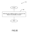
- the process 142 may comprise providing a tab on the grounding element of the airfoil.
- the tab may project radially outward from the platform of the airfoil to a predetermined height along a side of the airfoil.
- the present disclosure provides various configurations of a grounding element for an airfoil of a gas turbine engine.
- the disclosed configurations maintain positive contact between a leading edge sheath and a root of the airfoil. With the root of the airfoil contained within a rotor of the gas turbine engine, static electricity is discharged to the root, thereby minimizing or eliminating galvanic corrosion.
- the disclosed configurations maintain a high level of electrical conductivity in the ground path from the leading edge sheath to the root by more effectively sealing a joint between the leading edge sheath and the grounding element.
- a radially projecting tab on the grounding element ensures connection either directly with the sheath or to a collar which connects the sheath to the grounding element.
- the tab of the grounding element may provide more surface area for contact with the sheath or collar, thereby eliminating or minimizing any crevices between the sheath and the grounding element with and without the collar.
- the tab may be preloaded toward the sheath or the collar to enhance contact and conductivity between components.
- a multi-piece configuration for the grounding element may eliminate tolerance issues when the parts are assembled and improve sealing and alignment of the grounding element on the airfoil.
- the disclosed configurations provide a robust ground path from the sheath to the rotor, while also preventing ingress of water, in order to drastically reduce galvanic corrosion.
Landscapes
- Engineering & Computer Science (AREA)
- Mechanical Engineering (AREA)
- General Engineering & Computer Science (AREA)
- Chemical & Material Sciences (AREA)
- Architecture (AREA)
- Materials Engineering (AREA)
- Combustion & Propulsion (AREA)
- Structures Of Non-Positive Displacement Pumps (AREA)
Abstract
Description
- The present disclosure relates generally to gas turbine engines and, more particularly, to airfoils in a gas turbine engine.
- Gas turbine engines may typically include a fan, a compressor, a combustor, and a turbine, with an annular flow path extending axially through each. Initially, the fan, which is powered by the turbine, draws ambient air into the engine. Part of the air flows through the compressor where it is compressed or pressurized. The combustor then mixes and ignites the compressed air with fuel, generating hot combustion gases. These hot combustion gases are then directed from the combustor to the turbine where power is extracted from the hot gases by causing blades of the turbine to rotate. The other part of the airflow from the fan is used to generate forward thrust.
- Due to the large volume of air moving across the fan blades, static electric charge may build up. With fan blades composed of a conductive metal that was grounded to a hub, the static charge would dissipate. Recently, however, fan blades have been composed of aluminum in order to increase a size, but not a weight, of the blades. A titanium sheath may cover a leading edge of the fan blade, while a grounding element made of like material may be positioned on a platform and a root of the fan blade in order to from a ground path to dissipate the static charge buildup.
- However, in a saltwater environment (or other corrosive environment), a crevice between the sheath and the grounding element may retain saltwater particles (or other electrolyte particles). As a result, the ground path may be broken and galvanic corrosion may occur, thereby leading to an erosion of the leading edge and aluminum body. Accordingly, there exists a need for an improved configuration that provides a solid and reinforced ground path for the fan blades of a gas turbine engine.
- According to one embodiment, an airfoil for a gas turbine engine is disclosed. The airfoil may comprise a leading edge, a sheath on the leading edge; and a grounding element connected to the sheath. The grounding element may have a radially extending tab, and may be configured for connection to a component of the gas turbine engine to form a ground path from the sheath to the component.
- In a refinement, the airfoil may further comprise a collar overlapping the sheath and the tab of the grounding element.
- In another refinement, the tab may be preloaded toward the collar.
- In another refinement, the sheath may overlap the tab of the grounding element.
- In another refinement, the airfoil may further comprise a first side and an opposite second side extending radially outward from a platform to a tip; and a root extending radially inward from the platform, the grounding element being disposed on the platform and extending radially inward from the platform to the root, the tab projecting radially outward from the platform.
- In another refinement, the grounding element may include a platform cover disposed on a leading edge of the platform, and a strip extending from the platform cover to the root.
- In another refinement, the root may include a gradual bend from an under side of the platform to the root in order to enhance manufacturability of the strip.
- In another refinement, the strip may extend along a length of a leading edge of the root.
- In another refinement, the platform cover and the strip may comprise a multi-piece configuration.
- In another refinement, the platform cover may include a slot configured to receive an end of the strip.
- In another refinement, the platform may include a slot configured to receive an end of the strip.
- In another refinement, the grounding element may further include a dovetail cap extending from the strip and sized to cover a dovetail portion of a leading edge of the root.
- In another refinement, the dovetail portion of the leading edge of the root is shaped to fit within the dovetail cap.
- In another refinement, the platform cover, the strip, and the dovetail cap may comprise a three-piece configuration.
- In another refinement, the strip may include a multi-piece configuration including a first piece extending from the leading edge of the platform to an under side of the platform, and a second piece extending from the under side of the platform to the root.
- In another refinement, the platform cover may include a multi-piece configuration including a first piece extending circumferentially from a first side of the platform proximate to a centerline of the platform, and a second piece extending circumferentially proximate the centerline of the platform to a second side of the platform.
- According to another embodiment, which the Applicant expressly reserves the right to claim, an assembly for a gas turbine engine is disclosed. The assembly may comprise a fan section; a compressor section downstream of the fan section; a combustor section downstream of the compressor section; and a turbine section downstream of the combustor section. At least one of the fan section, the compressor section, and the turbine section may have an airfoil including a sheath disposed on a leading edge of the airfoil, and a grounding element disposed on a platform of the airfoil and extending radially inward from the platform to a root of the airfoil. The grounding element may include a tab projecting radially outward from the platform. The grounding element and the sheath may be connected to form a ground path from the sheath to a rotor in the at least one of the fan section, the compressor section, and the turbine section.
- In a refinement, a collar may connect the grounding element to the sheath.
- According to yet another embodiment, which the Applicant expressly reserves the right to claim, a method for increasing a connectivity between a sheath and a grounding element of an airfoil is disclosed. The method may comprise connecting the sheath of the airfoil to a tab on the grounding element of the airfoil, the tab projecting radially outward from a platform of the airfoil to a predetermined height along a side of the airfoil.
- In a refinement, the method may further comprise adhering the sheath on top of the tab.
- These and other aspects and features of the disclosure will become more readily apparent upon reading the following detailed description when taken in conjunction with the accompanying drawings. Although various features are disclosed in relation to specific exemplary embodiments of the invention, it is understood that the various features may be combined with each other, or used alone, with any of the various exemplary embodiments of the invention without departing from the scope of the invention.
-
-
FIG. 1 is a cross-sectional view of a gas turbine engine, according to an embodiment of the present disclosure; -
FIG. 2 is a side view of a first side of an airfoil in the gas turbine engine ofFIG. 1 ; -
FIG. 3 is a front view of the airfoil ofFIG. 2 within a rotor of the gas turbine engine; -
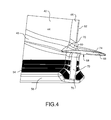
FIG. 4 is a perspective view of a portion of the airfoil ofFIG. 2 with a sheath, a grounding element, and a collar, according to another embodiment of the present disclosure; -
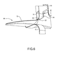
FIGS. 5 and6 are perspective views of the sheath, the grounding element, and the collar ofFIG. 4 ; -
FIGS. 7 and 8 are perspective views of the grounding element ofFIG. 4 ; -
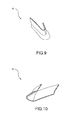
FIGS. 9 and 10 are perspective views of the collar ofFIG. 4 ; -
FIG. 11 is a perspective view of a piece of sheet metal used to make the grounding element ofFIG. 4 ; -
FIG. 12 is a perspective view of a pattern for the grounding element ofFIG. 4 cut from the piece of sheet metal ofFIG. 11 ; -
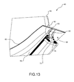
FIG. 13 is a perspective view of a portion of an airfoil with a gradual bend on an under side of a platform, according to another embodiment; -
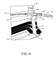
FIG. 14 is a perspective view of a portion of an airfoil with a sheath, a collar, and a multi-piece configuration for the grounding element, according to another embodiment; -
FIG. 15 is a perspective view of the sheath, the collar, and the multi-piece grounding element ofFIG. 14 ; -
FIGS. 16-18 are perspective views of a grounding element with a dovetail cap, according to another embodiment; -
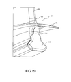
FIG. 19 is a perspective view of an airfoil shaped to fit the dovetail cap ofFIGS. 16-18 ; -
FIG. 20 is a perspective view of a grounding element with a strip and a dovetail cap integrated into one piece, according to another embodiment; -
FIG. 21 is a perspective view of a portion of an airfoil with a slot to accommodate an end of a strip of a grounding element, according to another embodiment; -
FIG. 22 is a perspective view of the airfoil ofFIG. 21 with a sheath, a collar, and a grounding element; -
FIG. 23 is a perspective view of a platform cover of the grounding element ofFIG. 22 ; -
FIG. 24 is a perspective view of a portion of an airfoil with a sheath and a grounding element, according to another embodiment; -
FIG. 25 is a perspective view of the sheath and the grounding element ofFIG. 24 ; -
FIGS. 26 and 27 are perspective views of the sheath ofFIG. 24 ; -
FIGS. 28 and 29 are perspective views of a grounding element including a strip with a dovetail section, according to another embodiment; -
FIGS. 30 and 31 are perspective views of a grounding element including a multi-piece configuration for a strip, according to another embodiment; -
FIGS. 32-34 are perspective view of a grounding element including a multi-piece configuration for a platform cover, according to another embodiment; and -
FIG. 35 is a flowchart outlining a process for increasing a connectivity between a sheath and a grounding element of the airfoil, according to another embodiment. - While the present disclosure is susceptible to various modifications and alternative constructions, certain illustrative embodiments thereof, will be shown and described below in detail. It should be understood, however, that there is no intention to be limited to the specific embodiments disclosed, but on the contrary, the intention is to cover all modifications, alternative constructions, and equivalents falling within the spirit and scope of the present disclosure.
- Referring now to the drawings, and with specific reference to
FIG. 1 , in accordance with the teachings of the disclosure, an exemplarygas turbine engine 20 is shown. Thegas turbine engine 20 may generally comprise afan section 22 which draws ambient air into theengine 20, acompressor section 24 where air is pressurized, acombustor 26 downstream of the compressor section which mixes and ignites the compressed air with fuel and thereby generates hot combustion gases, aturbine section 28 downstream of thecombustor 26 for extracting power from the hot combustion gases, and anannular flow path 30 extending axially through each.Gas turbine engine 20 may be used on an aircraft for generating thrust or power, or in land-based operations for generating power as well. - Turning now to
FIGS. 2 and3 , with continued reference toFIG. 1 , anairfoil 40 of thegas turbine engine 20 is shown. Theairfoil 40 may comprise a fan blade in thefan section 22, or a rotor blade or stator vane in thecompressor section 24 orturbine section 28 of thegas turbine engine 20.Airfoil 40 may comprise abody 42 that includes afirst side 44 and an oppositesecond side 46 projecting radially outward from aplatform 48 to atip 50. The first andsecond sides edge 52 to a trailing edge 54 (downstream of the leading edge 52). - The
airfoil 40 may also include aroot 56 extending from an underside 58 of theplatform 48. Theairfoil 40 may be installed or positioned within arotor 60 of theengine 20. For example, theroot 56 may be shaped to fit within a groove 62 of therotor 60. Although other materials are certainly possible, thebody 42,platform 48, and root 56 of theairfoil 40 may be composed of aluminum or various aluminum alloys. In addition, protective coatings, such as polyurethane and the like, may be applied to theairfoil 40. Theairfoil 40 may be solid, hollow, or a combination thereof. For example, theairfoil 40 may include channels, pockets, and filler materials (not shown). Furthermore,fabric wear pads 64 may be placed on theroot 56 of theairfoil 40. - As shown best in
FIGS. 4-10 , with continued reference toFIGS. 1-3 , asheath 66 may be secured to the leadingedge 52 of thebody 42 of theairfoil 40. For example, thesheath 66 may be bonded to thebody 42, such as, via a conductive bonding agent or other adhesive. Thesheath 66 may cover theleading edge 52 proximate theplatform 48 and extend to the tip 50 (FIG. 2 ). Thesheath 66 may strengthen theairfoil 40 against foreign object damage. Although other materials are certainly possible, thesheath 66 may be composed of titanium or various titanium alloys. - The
airfoil 40 may further include agrounding element 68 that provides a ground path from thesheath 66 to the rotor 60 (FIG. 3 ) in order to dissipate static electric charge buildup. Thegrounding element 68 may be secured on theplatform 48 and theroot 56 of theairfoil 40, such as, via a conductive bonding agent or other adhesive. More specifically, thegrounding element 68 may include aplatform cover 70 and astrip 72. Theplatform cover 70 may extend over a leadingedge 74 of theplatform 48, and thestrip 72 may extend from theplatform cover 70 radially inward to theroot 56 of theairfoil 40. Thestrip 72 may extend along theunder side 58 of theplatform 48 of theairfoil 40 to aleading edge 76 of theroot 56. Although other materials are certainly possible, thegrounding element 68 may be composed of a similar material as thesheath 66, such as, titanium or various titanium alloys. - To provide a reinforced ground path, the
grounding element 68 may include a tab 78 (FIGS. 5-8 ) projecting radially outward from theplatform cover 70. Thetab 78 may extend along thefirst side 44 of theairfoil 40 to a predetermined height h (FIG. 6 ). For example purposes only, the predetermined height h may be approximately 0.5 inch (12.7 mm), although other heights are certainly possible. An example widthw (FIG. 6 ) of thetab 78 may be approximately 0.5 inch (12.7 mm), although other widths are certainly possible. Although not shown, thetab 78 may also extend along thesecond side 46, leadingedge 52, or around bothsides edge 52 of thebody 42 of theairfoil 40. Furthermore, it is certainly possible for thegrounding element 68 to have more than onetab 78. - A collar 80 (
FIGS. 9 and 10 ) may be secured around thesheath 66 and thegrounding element 68 to ensure conductivity between thesheath 66 and thegrounding element 68 and fortify the ground path. For example, thecollar 80 may overlap thetab 78, an edge 82 (FIGS. 5-8 ) of thegrounding element 68, and an end 84 (FIGS. 5 and6 ) of thesheath 66. Thecollar 80 may be bonded to the grounding element 68 (e.g., to thetab 78 and edge 82),sheath 66, andbody 42 of theairfoil 40 via a conductive bonding agent or other adhesive. - The
tab 78 of thegrounding element 68 may be preloaded or biased toward thecollar 80 to enhance contact and ensure conductivity between components. For example, thetab 78 may be over-bent or bent towards thecollar 80 in a forming process. In addition, thetab 78 may not be bonded to thebody 42 of theairfoil 40 to allow a spring effect with thecollar 80. However, if desired, it is certainly possible to bond thetab 78 to thebody 42. - Although other materials are certainly possible, the
collar 80 may be composed of a similar material as thesheath 66 and thegrounding element 68, such as, titanium or various titanium alloys. The collar may have a height of approximately 0.75 inch (19.05 mm), although other heights are certainly possible. In addition, each of thesheath 66, groundingelement 68, andcollar 80 may have an approximate thickness within an inclusive range of 0.025 inch (0.635 mm) to 0.030 inch (0.762 mm), although other thicknesses are certainly possible. - Referring now to
FIGS. 11 and 12 , with continued reference toFIGS. 1-10 , thegrounding element 68 may be made through a serious of various processes. For example, a piece of sheet metal 86 (FIG. 11 ) may be bent, such as, via hot forming. Other processes, such as, die forming or hydroforming, may certainly be used. A pattern 88 (FIG. 12 ) of thegrounding element 68 may be cut from the piece ofbent sheet metal 86, such as, via a five axis laser or other cutting method. Thecut pattern 88 may then go through hot forming (or other processes) in order to mold thegrounding element 68 into a shape that fits around theairfoil 40 and provides for strong adhesion between the groundingelement 68 andairfoil 40. More specifically, the edge 82 (FIGS. 5-8 ) and thetab 78 may be bent or formed to a contour of thebody 42 of theairfoil 40, and thestrip 72 may be bent or formed to a contour of theunder side 58 of theplatform 48 and theroot 56 of theairfoil 40. Thesheath 66 and thecollar 80 may be formed via similar processes as thegrounding element 68. - Turning now to
FIG. 13 , with continued reference toFIGS. 1-12 , theroot 56 of theairfoil 40 may be configured to enhance manufacturability of thegrounding element 68. For example, theroot 56 may include agradual bend 90 from the underside 58 of theplatform 48 to the leadingedge 76 of theroot 56. Compared to prior art airfoils, there may be more material between theunder side 58 of theplatform 48 and the leadingedge 76 of theroot 56 such that there is a less acute angle at thegradual bend 90. In so doing, when thegrounding element 68 is formed, thestrip 72 does not have to be bent in an acute angle in order to conform with a contour of theairfoil 40, thereby enabling an ease of manufacturability of thestrip 72 and adhesion to thebend 90 on theunder side 58 of theplatform 48. - Referring now to
FIGS. 14 and15 , with continued reference toFIGS. 1-13 , thegrounding element 68 may comprise a multi-piece configuration. For example, theplatform cover 70 and thestrip 72 may be two separate pieces, as opposed to theplatform cover 70 and thestrip 72 being integrated into one piece. In addition, theplatform cover 70 may include a slot 92 configured to receive anend 94 of thestrip 72. Thestrip 72 may extend proximate to a bottom 96 of the leadingedge 76 of theroot 56 and may be substantially rectangular in shape, although other shapes are certainly possible. With a multi-piece configuration, a bending of thestrip 72 during manufacture to match an angle of theunderside 58 of theplatform 48 and the leadingedge 76 of theroot 56 may be less difficult. There may also be improved sealing and alignment when the parts are assembled, thereby eliminating tolerance issues and minimizing galvanic corrosion. - Turning now to
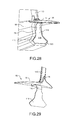
FIGS. 16-19 , with continued reference toFIGS. 1-15 , thegrounding element 68 may also include adovetail cap 98. Thedovetail cap 98 may be a separate piece from theplatform cover 70 and thestrip 72 and may be sized to cover adovetail portion 100 of the leadingedge 76 of theroot 56. In addition, thedovetail portion 100 of the leadingedge 76 of theroot 56 may be shaped to fit within thedovetail cap 98. As shown best inFIG. 19 , thedovetail portion 100 of the leadingedge 76 may be machined such that it has a reduced volume than arest 102 of theroot 56, and the dovetail cap 98 (FIGS. 16-18 ) may be attached without adding extra weight or volume to theairfoil 40. - In addition, the
dovetail cap 98 may be secured to thedovetail portion 100 of the leadingedge 76 of theroot 56, such as, via a conductive bonding agent or other adhesive. Thestrip 72 may be bonded over thedovetail cap 98 and may not extend proximate to the bottom 96 of theroot 56. However, other configurations are certainly possible. Although other materials are possible, thedovetail cap 98 may be composed of a similar material as thesheath 66,platform cover 70, andstrip 72, such as, titanium or various titanium allows. Thedovetail cap 98 may be formed via hot forming or other suitable processes. - By including the
dovetail cap 98, there may be a greater bonding area for thegrounding element 68, and therefore, a stronger bond to theairfoil 40. In so doing, there may be improved sealing and assembly, thereby minimizing galvanic corrosion. Furthermore, although shown as two separate pieces, thestrip 72 anddovetail cap 98 may be one integral piece. For example, as shown best inFIG. 20 , astrip 104 of thegrounding element 68 may have an integrateddovetail cap portion 106. - Referring now to
FIGS 21-23 , with continued reference toFIGS. 1-20 , the leadingedge 74 of theplatform 48 may include aslot 108 configured to receive theend 94 of thestrip 72. Thestrip 72 may be embedded and secured within theslot 108 on theairfoil 40. In so doing, a forward protrusion of theplatform cover 70 of thegrounding element 68 may be eliminated when a multi-piece configuration is used for theplatform cover 70 and thestrip 72. - Turning now to
FIGS. 24-27 , with continued reference toFIGS. 1-23 , instead of using the collar 80 (FIGS. 9 and 10 ), asheath 110 may be directly connected to and extend over the groundingelement 68. For example, anend 112 of thesheath 110 may overlap and be secured to thetab 78 and theedge 82 of thegrounding element 68. Thesheath 110 may include arecess 114 to receivetab 78 of thegrounding element 68, and thetab 78 may be secured to therecess 114 of thesheath 110. Furthermore, thetab 78 may be preloaded or biased toward thesheath 110 to enhance contact and ensure conductivity between components. In addition to being bonded to thebody 42 of theairfoil 40, thesheath 110 may be bonded to thegrounding element 68, such as, via a conductive bonding agent or other adhesive. - Referring now to
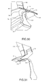
FIGS 28 and 29 , with continued reference toFIGS. 1-27 , astrip 116 may have adovetail section 118. Thestrip 116 may not have a dovetail cap 98 (FIGS. 16-18 ) that fits over the entire leadingedge 76 of the root. Instead, thedovetail section 118 of thestrip 116 may have a similar shape as thedovetail portion 100 of the leadingedge 76 of theroot 56 and may fit inside aperimeter 120 of the leadingedge 76. Thedovetail section 118 may be shaped to maximize a bond area of thestrip 116 with the leadingedge 76 of theroot 56, which may lead to improved conductivity of the ground path. - Referring now to
FIGS. 30 and 31 , with continued reference toFIGS. 1-29 , thestrip 116 may comprise a multi-piece configuration including afirst piece 122 and asecond piece 124. In this embodiment, thefirst piece 122 may extend from the leadingedge 74 of theplatform 48 to theunder side 58 of theplatform 48, and thesecond piece 124 may extend from the underside 58 of theplatform 48 to the leadingedge 76 of theroot 56. Embedded in theslot 108 of the leadingedge 74 of theplatform 48, thefirst piece 122 may connect theplatform cover 70 to thesecond piece 124. In so doing, there may be improved formation of under-platform bends in thegrounding element 68. In addition, the multi-piece configuration may ensure electrical conductivity and eliminate tolerances issues through improved sealing and alignment when the parts are assembled. - Turning now to
FIGS. 32-34 , theplatform cover 70 may comprise a multi-piece configuration including afirst piece 126 and asecond piece 128. Thefirst piece 126 may extend circumferentially from afirst side 130 of the platform 48 (and afirst side 44 of the airfoil 40) proximate to acenterline 132 of theplatform 48. Thesecond piece 128 may extend circumferentially proximate the centerline132 ofplatform 48 to asecond side 134 of the platform 48 (and asecond side 46 of the airfoil 40). In addition, thesheath 110 may overlap both thefirst piece 126 and thesecond piece 128 of theplatform cover 70. - The
centerline 132 may follow a camber of theairfoil 40 to the leadingedge 74 of theplatform 48 and may be disposed on a center of the leadingedge 52 of thebody 42 of theairfoil 40. However, thecenterline 132 may be located anywhere between thefirst side 130 andsecond side 134 of theplatform 48. Thesecond piece 128 of theplatform cover 70 may extend over an end 136 of thefirst piece 122 of thestrip 116, although in other configurations, the first piece 126 (or bothpieces 126, 128) of theplatform cover 70 may cover the end 136 of thefirst piece 122 of thestrip 116. - Turning now to
FIG. 35 , with continued reference toFIGS. 1-34 , a flowchart outlining aprocess 140 for increasing the connectivity between the sheath and the grounding element of the airfoil is shown. Theprocess 142 may comprise providing a tab on the grounding element of the airfoil. The tab may project radially outward from the platform of the airfoil to a predetermined height along a side of the airfoil. - Although various features are disclosed in relation to specific embodiments, it is understood that the various features may be combined with each other, or used alone, with any of the various embodiments disclosed.
- From the foregoing, it can be seen that the teachings of this disclosure can find industrial application in any number of different situations, including but not limited to, gas turbine engines. Such engines may be used, for example, on aircraft for generating thrust, or in land, marine, or aircraft applications for generating power.
- The present disclosure provides various configurations of a grounding element for an airfoil of a gas turbine engine. The disclosed configurations maintain positive contact between a leading edge sheath and a root of the airfoil. With the root of the airfoil contained within a rotor of the gas turbine engine, static electricity is discharged to the root, thereby minimizing or eliminating galvanic corrosion.
- Furthermore, the disclosed configurations maintain a high level of electrical conductivity in the ground path from the leading edge sheath to the root by more effectively sealing a joint between the leading edge sheath and the grounding element. More specifically, a radially projecting tab on the grounding element ensures connection either directly with the sheath or to a collar which connects the sheath to the grounding element. The tab of the grounding element may provide more surface area for contact with the sheath or collar, thereby eliminating or minimizing any crevices between the sheath and the grounding element with and without the collar.
- Moreover, the tab may be preloaded toward the sheath or the collar to enhance contact and conductivity between components. In addition, a multi-piece configuration for the grounding element may eliminate tolerance issues when the parts are assembled and improve sealing and alignment of the grounding element on the airfoil. Thus, by minimizing crevices between the sheath and the grounding element, the disclosed configurations provide a robust ground path from the sheath to the rotor, while also preventing ingress of water, in order to drastically reduce galvanic corrosion.
- While the foregoing detailed description has been given and provided with respect to certain specific embodiments, it is to be understood that the scope of the disclosure should not be limited to such embodiments, but that the same are provided simply for enablement and best mode purposes. The breadth and spirit of the present disclosure is broader than the embodiments specifically disclosed, but rather includes all embodiments and equivalents encompassed within the claims appended hereto as well.
Claims (15)
- An airfoil (40) for a gas turbine engine, comprising:a leading edge (52);a sheath (66) on the leading edge (52); anda grounding element (68) connected to the sheath (66), having a radially extending tab (78), and configured for connection to a component of the gas turbine engine to form a ground path from the sheath (66) to the component.
- The airfoil of claim 1, further comprising a collar (80) overlapping the sheath (66) and the tab (78) of the grounding element (68), wherein, optionally, the tab (78) is preloaded toward the collar (80).
- The airfoil of claim 1 or 2, wherein the sheath (66) overlaps the tab (78) of the grounding element (68).
- The airfoil of any preceding claim, further comprising:a first side (44) and an opposite second side (46) extending radially outward from a platform (48) to a tip (50); anda root (56) extending radially inward from the platform (48), the grounding element (68) being disposed on the platform (48) and extending radially inward from the platform (48) to the root (56), the tab (78) projecting radially outward from the platform (48).
- The airfoil of claim 4, wherein the grounding element (68) includes a platform cover (70) disposed on a leading edge (74) of the platform (70), and a strip (72) extending from the platform cover (70) to the root (56).
- The airfoil of claim 4 or 5, wherein the root (56) includes a gradual bend from an under side (58) of the platform (48) to the root (56) in order to enhance manufacturability of the strip (72).
- The airfoil of claim 4, 5 or 6, wherein the strip (72) extends along a length of a leading edge (76) of the root (56).
- The airfoil of any of claims 5 to 7, wherein the platform cover (70) and the strip (72) comprise a multi-piece configuration.
- The airfoil of any of claims 5 to 8, wherein the platform cover (70) includes a slot (92) configured to receive an end (94) of the strip (72).
- The airfoil of any of claims 4 to 9, wherein the platform (48) of the airfoil (40) includes a slot (108) configured to receive an end (94) of the strip (72).
- The airfoil of any of claims 4 to 10, wherein the grounding element (68) further includes a dovetail cap extending from the strip (72) and sized to cover a dovetail portion (100) of a leading edge (76) of the root (56).
- The airfoil of claim 11, wherein the dovetail portion (100) of the leading edge (76) of the root (56) is shaped to fit within the dovetail cap (68).
- The airfoil of claim 12, wherein the platform cover (70), the strip (72), and the dovetail cap (78) comprise a three-piece configuration.
- The airfoil of any of claims 4 to 13, wherein the strip (72) includes a multi-piece configuration including a first piece (122) extending from the leading edge (74) of the platform (70) to an under side (58) of the platform (48), and a second piece (124) extending from the under side (58) of the platform (48) to the root (56), wherein, optionally, the platform cover (70) includes a multi-piece configuration including a first piece (126) extending circumferentially from a first side (130) of the platform (48) proximate to a centerline (132) of the platform (48), and a second piece (128) extending circumferentially proximate the centerline (132) of the platform (48) to a second side (134) of the platform (48).
- An assembly for a gas turbine engine, comprising:a fan section (22);a compressor section (24) downstream of the fan section (22);a combustor section (26) downstream of the compressor section (24);
anda turbine section (28) downstream of the combustor section (26), at least one of the fan section (22), the compressor section (24), and the turbine section (28) having an airfoil as claimed in any preceding claim, the grounding element (68) and the sheath (66) being connected to form a ground path from the sheath (66) to a rotor in the at least one of the fan section (22), the compressor section (24), and the turbine section (28).
Applications Claiming Priority (1)
| Application Number | Priority Date | Filing Date | Title |
|---|---|---|---|
| US201462010549P | 2014-06-11 | 2014-06-11 |
Publications (2)
| Publication Number | Publication Date |
|---|---|
| EP2955326A1 true EP2955326A1 (en) | 2015-12-16 |
| EP2955326B1 EP2955326B1 (en) | 2019-07-31 |
Family
ID=53489796
Family Applications (1)
| Application Number | Title | Priority Date | Filing Date |
|---|---|---|---|
| EP15171738.6A Active EP2955326B1 (en) | 2014-06-11 | 2015-06-11 | Gas turbine airfoil with a grounding element |
Country Status (2)
| Country | Link |
|---|---|
| US (1) | US10107105B2 (en) |
| EP (1) | EP2955326B1 (en) |
Cited By (3)
| Publication number | Priority date | Publication date | Assignee | Title |
|---|---|---|---|---|
| EP3054097A1 (en) * | 2015-02-09 | 2016-08-10 | United Technologies Corporation | Fan blade root |
| EP3382145A1 (en) * | 2017-03-27 | 2018-10-03 | United Technologies Corporation | Apparatus and method for non-destructive detection of fan blade electrical isolation |
| EP3653837A1 (en) * | 2018-11-19 | 2020-05-20 | United Technologies Corporation | Grounding clip for bonded vanes |
Citations (1)
| Publication number | Priority date | Publication date | Assignee | Title |
|---|---|---|---|---|
| EP2604794A1 (en) * | 2011-12-14 | 2013-06-19 | United Technologies Corporation | Electrical Grounding for Fan Blades |
Family Cites Families (6)
| Publication number | Priority date | Publication date | Assignee | Title |
|---|---|---|---|---|
| US6004101A (en) * | 1998-08-17 | 1999-12-21 | General Electric Company | Reinforced aluminum fan blade |
| US8376712B2 (en) * | 2010-01-26 | 2013-02-19 | United Technologies Corporation | Fan airfoil sheath |
| US9650897B2 (en) * | 2010-02-26 | 2017-05-16 | United Technologies Corporation | Hybrid metal fan blade |
| US8876482B2 (en) * | 2012-09-11 | 2014-11-04 | United Technologies Corporation | Electrical grounding for blade sheath |
| US9322283B2 (en) * | 2012-09-28 | 2016-04-26 | United Technologies Corporation | Airfoil with galvanic corrosion preventive shim |
| US9617860B2 (en) * | 2012-12-20 | 2017-04-11 | United Technologies Corporation | Fan blades for gas turbine engines with reduced stress concentration at leading edge |
-
2015
- 2015-06-10 US US14/735,770 patent/US10107105B2/en active Active
- 2015-06-11 EP EP15171738.6A patent/EP2955326B1/en active Active
Patent Citations (1)
| Publication number | Priority date | Publication date | Assignee | Title |
|---|---|---|---|---|
| EP2604794A1 (en) * | 2011-12-14 | 2013-06-19 | United Technologies Corporation | Electrical Grounding for Fan Blades |
Cited By (5)
| Publication number | Priority date | Publication date | Assignee | Title |
|---|---|---|---|---|
| EP3054097A1 (en) * | 2015-02-09 | 2016-08-10 | United Technologies Corporation | Fan blade root |
| US10570755B2 (en) | 2015-02-09 | 2020-02-25 | United Technologies Corporation | Fan blade root |
| EP3382145A1 (en) * | 2017-03-27 | 2018-10-03 | United Technologies Corporation | Apparatus and method for non-destructive detection of fan blade electrical isolation |
| US10345799B2 (en) | 2017-03-27 | 2019-07-09 | United Technologies Corporation | Apparatus and method for non-destructive detection of fan blade electrical isolation |
| EP3653837A1 (en) * | 2018-11-19 | 2020-05-20 | United Technologies Corporation | Grounding clip for bonded vanes |
Also Published As
| Publication number | Publication date |
|---|---|
| EP2955326B1 (en) | 2019-07-31 |
| US10107105B2 (en) | 2018-10-23 |
| US20160047247A1 (en) | 2016-02-18 |
Similar Documents
| Publication | Publication Date | Title |
|---|---|---|
| US10138738B2 (en) | Composite vane | |
| EP2809885B1 (en) | Rotary fan blade and corresponding assembly | |
| US10815798B2 (en) | Turbine engine blade with leading edge strip | |
| US8672634B2 (en) | Electroformed conforming rubstrip | |
| EP2971559B1 (en) | Blade assembly with wear pads, gas turbine engine and method of manufacturing a blade assembly | |
| CA2880602C (en) | Shrouded blade for a gas turbine engine | |
| US10107105B2 (en) | Fan blade grounding tab | |
| US11278992B2 (en) | Methods of manufacturing a tandem guide vane segment | |
| US10883374B2 (en) | Blade comprising a folded leading edge shield and method of manufacturing the blade | |
| US10876415B2 (en) | Fan blade tip as a cutting tool | |
| US10323521B2 (en) | Hybrid fan blade biscuit construction | |
| CN105283639A (en) | A turbomachine component with a stress relief cavity | |
| EP3318717B1 (en) | Undercut on airfoil coversheet support member | |
| EP3244020A2 (en) | Gas turbine engine having a vane assembly | |
| EP2930306B1 (en) | Gas turbine engine fan with discrete platforms for electrically grounding sheaths of fan airfoils | |
| US9835040B2 (en) | Turbomachine | |
| EP2971527B1 (en) | Hybrid fan blade biscuit construction | |
| US10934847B2 (en) | Steam turbine rotor blade, steam turbine, and method for manufacturing steam turbine rotor blade | |
| US10612386B2 (en) | Apparatus for airfoil leading edge protection | |
| JP6614467B2 (en) | Steam turbine blade, steam turbine, and method of manufacturing steam turbine blade | |
| US10371162B2 (en) | Integrally bladed fan rotor | |
| US10634158B2 (en) | Blade with a platform and a hollow bumper |
Legal Events
| Date | Code | Title | Description |
|---|---|---|---|
| PUAI | Public reference made under article 153(3) epc to a published international application that has entered the european phase |
Free format text: ORIGINAL CODE: 0009012 |
|
| AK | Designated contracting states |
Kind code of ref document: A1 Designated state(s): AL AT BE BG CH CY CZ DE DK EE ES FI FR GB GR HR HU IE IS IT LI LT LU LV MC MK MT NL NO PL PT RO RS SE SI SK SM TR |
|
| AX | Request for extension of the european patent |
Extension state: BA ME |
|
| 17P | Request for examination filed |
Effective date: 20160616 |
|
| RBV | Designated contracting states (corrected) |
Designated state(s): AL AT BE BG CH CY CZ DE DK EE ES FI FR GB GR HR HU IE IS IT LI LT LU LV MC MK MT NL NO PL PT RO RS SE SI SK SM TR |
|
| RAP1 | Party data changed (applicant data changed or rights of an application transferred) |
Owner name: UNITED TECHNOLOGIES CORPORATION |
|
| GRAP | Despatch of communication of intention to grant a patent |
Free format text: ORIGINAL CODE: EPIDOSNIGR1 |
|
| STAA | Information on the status of an ep patent application or granted ep patent |
Free format text: STATUS: GRANT OF PATENT IS INTENDED |
|
| INTG | Intention to grant announced |
Effective date: 20181218 |
|
| GRAS | Grant fee paid |
Free format text: ORIGINAL CODE: EPIDOSNIGR3 |
|
| GRAA | (expected) grant |
Free format text: ORIGINAL CODE: 0009210 |
|
| STAA | Information on the status of an ep patent application or granted ep patent |
Free format text: STATUS: THE PATENT HAS BEEN GRANTED |
|
| AK | Designated contracting states |
Kind code of ref document: B1 Designated state(s): AL AT BE BG CH CY CZ DE DK EE ES FI FR GB GR HR HU IE IS IT LI LT LU LV MC MK MT NL NO PL PT RO RS SE SI SK SM TR |
|
| REG | Reference to a national code |
Ref country code: CH Ref legal event code: EP Ref country code: GB Ref legal event code: FG4D |
|
| REG | Reference to a national code |
Ref country code: AT Ref legal event code: REF Ref document number: 1161095 Country of ref document: AT Kind code of ref document: T Effective date: 20190815 |
|
| REG | Reference to a national code |
Ref country code: IE Ref legal event code: FG4D |
|
| REG | Reference to a national code |
Ref country code: DE Ref legal event code: R096 Ref document number: 602015034659 Country of ref document: DE |
|
| REG | Reference to a national code |
Ref country code: NL Ref legal event code: MP Effective date: 20190731 |
|
| REG | Reference to a national code |
Ref country code: LT Ref legal event code: MG4D |
|
| REG | Reference to a national code |
Ref country code: AT Ref legal event code: MK05 Ref document number: 1161095 Country of ref document: AT Kind code of ref document: T Effective date: 20190731 |
|
| PG25 | Lapsed in a contracting state [announced via postgrant information from national office to epo] |
Ref country code: NO Free format text: LAPSE BECAUSE OF FAILURE TO SUBMIT A TRANSLATION OF THE DESCRIPTION OR TO PAY THE FEE WITHIN THE PRESCRIBED TIME-LIMIT Effective date: 20191031 Ref country code: BG Free format text: LAPSE BECAUSE OF FAILURE TO SUBMIT A TRANSLATION OF THE DESCRIPTION OR TO PAY THE FEE WITHIN THE PRESCRIBED TIME-LIMIT Effective date: 20191031 Ref country code: AT Free format text: LAPSE BECAUSE OF FAILURE TO SUBMIT A TRANSLATION OF THE DESCRIPTION OR TO PAY THE FEE WITHIN THE PRESCRIBED TIME-LIMIT Effective date: 20190731 Ref country code: PT Free format text: LAPSE BECAUSE OF FAILURE TO SUBMIT A TRANSLATION OF THE DESCRIPTION OR TO PAY THE FEE WITHIN THE PRESCRIBED TIME-LIMIT Effective date: 20191202 Ref country code: NL Free format text: LAPSE BECAUSE OF FAILURE TO SUBMIT A TRANSLATION OF THE DESCRIPTION OR TO PAY THE FEE WITHIN THE PRESCRIBED TIME-LIMIT Effective date: 20190731 Ref country code: FI Free format text: LAPSE BECAUSE OF FAILURE TO SUBMIT A TRANSLATION OF THE DESCRIPTION OR TO PAY THE FEE WITHIN THE PRESCRIBED TIME-LIMIT Effective date: 20190731 Ref country code: LT Free format text: LAPSE BECAUSE OF FAILURE TO SUBMIT A TRANSLATION OF THE DESCRIPTION OR TO PAY THE FEE WITHIN THE PRESCRIBED TIME-LIMIT Effective date: 20190731 Ref country code: SE Free format text: LAPSE BECAUSE OF FAILURE TO SUBMIT A TRANSLATION OF THE DESCRIPTION OR TO PAY THE FEE WITHIN THE PRESCRIBED TIME-LIMIT Effective date: 20190731 Ref country code: HR Free format text: LAPSE BECAUSE OF FAILURE TO SUBMIT A TRANSLATION OF THE DESCRIPTION OR TO PAY THE FEE WITHIN THE PRESCRIBED TIME-LIMIT Effective date: 20190731 |
|
| PG25 | Lapsed in a contracting state [announced via postgrant information from national office to epo] |
Ref country code: AL Free format text: LAPSE BECAUSE OF FAILURE TO SUBMIT A TRANSLATION OF THE DESCRIPTION OR TO PAY THE FEE WITHIN THE PRESCRIBED TIME-LIMIT Effective date: 20190731 Ref country code: IS Free format text: LAPSE BECAUSE OF FAILURE TO SUBMIT A TRANSLATION OF THE DESCRIPTION OR TO PAY THE FEE WITHIN THE PRESCRIBED TIME-LIMIT Effective date: 20191130 Ref country code: RS Free format text: LAPSE BECAUSE OF FAILURE TO SUBMIT A TRANSLATION OF THE DESCRIPTION OR TO PAY THE FEE WITHIN THE PRESCRIBED TIME-LIMIT Effective date: 20190731 Ref country code: LV Free format text: LAPSE BECAUSE OF FAILURE TO SUBMIT A TRANSLATION OF THE DESCRIPTION OR TO PAY THE FEE WITHIN THE PRESCRIBED TIME-LIMIT Effective date: 20190731 Ref country code: ES Free format text: LAPSE BECAUSE OF FAILURE TO SUBMIT A TRANSLATION OF THE DESCRIPTION OR TO PAY THE FEE WITHIN THE PRESCRIBED TIME-LIMIT Effective date: 20190731 Ref country code: GR Free format text: LAPSE BECAUSE OF FAILURE TO SUBMIT A TRANSLATION OF THE DESCRIPTION OR TO PAY THE FEE WITHIN THE PRESCRIBED TIME-LIMIT Effective date: 20191101 |
|
| PG25 | Lapsed in a contracting state [announced via postgrant information from national office to epo] |
Ref country code: TR Free format text: LAPSE BECAUSE OF FAILURE TO SUBMIT A TRANSLATION OF THE DESCRIPTION OR TO PAY THE FEE WITHIN THE PRESCRIBED TIME-LIMIT Effective date: 20190731 |
|
| PG25 | Lapsed in a contracting state [announced via postgrant information from national office to epo] |
Ref country code: IT Free format text: LAPSE BECAUSE OF FAILURE TO SUBMIT A TRANSLATION OF THE DESCRIPTION OR TO PAY THE FEE WITHIN THE PRESCRIBED TIME-LIMIT Effective date: 20190731 Ref country code: RO Free format text: LAPSE BECAUSE OF FAILURE TO SUBMIT A TRANSLATION OF THE DESCRIPTION OR TO PAY THE FEE WITHIN THE PRESCRIBED TIME-LIMIT Effective date: 20190731 Ref country code: DK Free format text: LAPSE BECAUSE OF FAILURE TO SUBMIT A TRANSLATION OF THE DESCRIPTION OR TO PAY THE FEE WITHIN THE PRESCRIBED TIME-LIMIT Effective date: 20190731 Ref country code: PL Free format text: LAPSE BECAUSE OF FAILURE TO SUBMIT A TRANSLATION OF THE DESCRIPTION OR TO PAY THE FEE WITHIN THE PRESCRIBED TIME-LIMIT Effective date: 20190731 Ref country code: EE Free format text: LAPSE BECAUSE OF FAILURE TO SUBMIT A TRANSLATION OF THE DESCRIPTION OR TO PAY THE FEE WITHIN THE PRESCRIBED TIME-LIMIT Effective date: 20190731 |
|
| PG25 | Lapsed in a contracting state [announced via postgrant information from national office to epo] |
Ref country code: CZ Free format text: LAPSE BECAUSE OF FAILURE TO SUBMIT A TRANSLATION OF THE DESCRIPTION OR TO PAY THE FEE WITHIN THE PRESCRIBED TIME-LIMIT Effective date: 20190731 Ref country code: IS Free format text: LAPSE BECAUSE OF FAILURE TO SUBMIT A TRANSLATION OF THE DESCRIPTION OR TO PAY THE FEE WITHIN THE PRESCRIBED TIME-LIMIT Effective date: 20200224 Ref country code: SM Free format text: LAPSE BECAUSE OF FAILURE TO SUBMIT A TRANSLATION OF THE DESCRIPTION OR TO PAY THE FEE WITHIN THE PRESCRIBED TIME-LIMIT Effective date: 20190731 Ref country code: SK Free format text: LAPSE BECAUSE OF FAILURE TO SUBMIT A TRANSLATION OF THE DESCRIPTION OR TO PAY THE FEE WITHIN THE PRESCRIBED TIME-LIMIT Effective date: 20190731 |
|
| REG | Reference to a national code |
Ref country code: DE Ref legal event code: R097 Ref document number: 602015034659 Country of ref document: DE |
|
| PLBE | No opposition filed within time limit |
Free format text: ORIGINAL CODE: 0009261 |
|
| STAA | Information on the status of an ep patent application or granted ep patent |
Free format text: STATUS: NO OPPOSITION FILED WITHIN TIME LIMIT |
|
| PG2D | Information on lapse in contracting state deleted |
Ref country code: IS |
|
| PG25 | Lapsed in a contracting state [announced via postgrant information from national office to epo] |
Ref country code: IS Free format text: LAPSE BECAUSE OF FAILURE TO SUBMIT A TRANSLATION OF THE DESCRIPTION OR TO PAY THE FEE WITHIN THE PRESCRIBED TIME-LIMIT Effective date: 20191030 |
|
| 26N | No opposition filed |
Effective date: 20200603 |
|
| PG25 | Lapsed in a contracting state [announced via postgrant information from national office to epo] |
Ref country code: SI Free format text: LAPSE BECAUSE OF FAILURE TO SUBMIT A TRANSLATION OF THE DESCRIPTION OR TO PAY THE FEE WITHIN THE PRESCRIBED TIME-LIMIT Effective date: 20190731 |
|
| PG25 | Lapsed in a contracting state [announced via postgrant information from national office to epo] |
Ref country code: MC Free format text: LAPSE BECAUSE OF FAILURE TO SUBMIT A TRANSLATION OF THE DESCRIPTION OR TO PAY THE FEE WITHIN THE PRESCRIBED TIME-LIMIT Effective date: 20190731 |
|
| REG | Reference to a national code |
Ref country code: CH Ref legal event code: PL |
|
| PG25 | Lapsed in a contracting state [announced via postgrant information from national office to epo] |
Ref country code: LU Free format text: LAPSE BECAUSE OF NON-PAYMENT OF DUE FEES Effective date: 20200611 |
|
| REG | Reference to a national code |
Ref country code: BE Ref legal event code: MM Effective date: 20200630 |
|
| PG25 | Lapsed in a contracting state [announced via postgrant information from national office to epo] |
Ref country code: CH Free format text: LAPSE BECAUSE OF NON-PAYMENT OF DUE FEES Effective date: 20200630 Ref country code: IE Free format text: LAPSE BECAUSE OF NON-PAYMENT OF DUE FEES Effective date: 20200611 Ref country code: LI Free format text: LAPSE BECAUSE OF NON-PAYMENT OF DUE FEES Effective date: 20200630 |
|
| PG25 | Lapsed in a contracting state [announced via postgrant information from national office to epo] |
Ref country code: BE Free format text: LAPSE BECAUSE OF NON-PAYMENT OF DUE FEES Effective date: 20200630 |
|
| PG25 | Lapsed in a contracting state [announced via postgrant information from national office to epo] |
Ref country code: MT Free format text: LAPSE BECAUSE OF FAILURE TO SUBMIT A TRANSLATION OF THE DESCRIPTION OR TO PAY THE FEE WITHIN THE PRESCRIBED TIME-LIMIT Effective date: 20190731 Ref country code: CY Free format text: LAPSE BECAUSE OF FAILURE TO SUBMIT A TRANSLATION OF THE DESCRIPTION OR TO PAY THE FEE WITHIN THE PRESCRIBED TIME-LIMIT Effective date: 20190731 |
|
| PG25 | Lapsed in a contracting state [announced via postgrant information from national office to epo] |
Ref country code: MK Free format text: LAPSE BECAUSE OF FAILURE TO SUBMIT A TRANSLATION OF THE DESCRIPTION OR TO PAY THE FEE WITHIN THE PRESCRIBED TIME-LIMIT Effective date: 20190731 |
|
| REG | Reference to a national code |
Ref country code: DE Ref legal event code: R081 Ref document number: 602015034659 Country of ref document: DE Owner name: RAYTHEON TECHNOLOGIES CORPORATION (N.D.GES.D.S, US Free format text: FORMER OWNER: UNITED TECHNOLOGIES CORPORATION, FARMINGTON, CONN., US Ref country code: DE Ref legal event code: R081 Ref document number: 602015034659 Country of ref document: DE Owner name: RTX CORPORATION (N.D.GES.D. STAATES DELAWARE),, US Free format text: FORMER OWNER: UNITED TECHNOLOGIES CORPORATION, FARMINGTON, CONN., US |
|
| P01 | Opt-out of the competence of the unified patent court (upc) registered |
Effective date: 20230520 |
|
| PGFP | Annual fee paid to national office [announced via postgrant information from national office to epo] |
Ref country code: DE Payment date: 20250520 Year of fee payment: 11 |
|
| PGFP | Annual fee paid to national office [announced via postgrant information from national office to epo] |
Ref country code: GB Payment date: 20250520 Year of fee payment: 11 |
|
| PGFP | Annual fee paid to national office [announced via postgrant information from national office to epo] |
Ref country code: FR Payment date: 20250520 Year of fee payment: 11 |
|
| REG | Reference to a national code |
Ref country code: DE Ref legal event code: R081 Ref document number: 602015034659 Country of ref document: DE Owner name: RTX CORPORATION (N.D.GES.D. STAATES DELAWARE),, US Free format text: FORMER OWNER: RAYTHEON TECHNOLOGIES CORPORATION (N.D.GES.D.STAATES DELAWARE), ARLINGTON, VA, US |