EP2955319A1 - Arrangement and method for feeding flushing fluid - Google Patents
Arrangement and method for feeding flushing fluid Download PDFInfo
- Publication number
- EP2955319A1 EP2955319A1 EP14172341.1A EP14172341A EP2955319A1 EP 2955319 A1 EP2955319 A1 EP 2955319A1 EP 14172341 A EP14172341 A EP 14172341A EP 2955319 A1 EP2955319 A1 EP 2955319A1
- Authority
- EP
- European Patent Office
- Prior art keywords
- flushing
- pump
- flushing fluid
- pressure
- flushing system
- Prior art date
- Legal status (The legal status is an assumption and is not a legal conclusion. Google has not performed a legal analysis and makes no representation as to the accuracy of the status listed.)
- Withdrawn
Links
- 238000011010 flushing procedure Methods 0.000 title claims abstract description 202
- 239000012530 fluid Substances 0.000 title claims abstract description 82
- 238000000034 method Methods 0.000 title claims abstract description 11
- 238000005553 drilling Methods 0.000 claims abstract description 78
- 239000011435 rock Substances 0.000 claims abstract description 22
- 239000003595 mist Substances 0.000 claims description 17
- XLYOFNOQVPJJNP-UHFFFAOYSA-N water Substances O XLYOFNOQVPJJNP-UHFFFAOYSA-N 0.000 claims description 10
- 238000006073 displacement reaction Methods 0.000 claims description 5
- 230000004044 response Effects 0.000 claims description 5
- 238000012544 monitoring process Methods 0.000 claims description 3
- 238000005086 pumping Methods 0.000 abstract description 6
- 239000007788 liquid Substances 0.000 description 9
- 239000000463 material Substances 0.000 description 8
- 230000007423 decrease Effects 0.000 description 5
- 238000005520 cutting process Methods 0.000 description 4
- 238000005259 measurement Methods 0.000 description 4
- 238000009527 percussion Methods 0.000 description 4
- 238000010586 diagram Methods 0.000 description 2
- 238000004519 manufacturing process Methods 0.000 description 1
- 230000005055 memory storage Effects 0.000 description 1
Images

Classifications
-
- E—FIXED CONSTRUCTIONS
- E21—EARTH OR ROCK DRILLING; MINING
- E21B—EARTH OR ROCK DRILLING; OBTAINING OIL, GAS, WATER, SOLUBLE OR MELTABLE MATERIALS OR A SLURRY OF MINERALS FROM WELLS
- E21B21/00—Methods or apparatus for flushing boreholes, e.g. by use of exhaust air from motor
- E21B21/08—Controlling or monitoring pressure or flow of drilling fluid, e.g. automatic filling of boreholes, automatic control of bottom pressure
-
- E—FIXED CONSTRUCTIONS
- E21—EARTH OR ROCK DRILLING; MINING
- E21B—EARTH OR ROCK DRILLING; OBTAINING OIL, GAS, WATER, SOLUBLE OR MELTABLE MATERIALS OR A SLURRY OF MINERALS FROM WELLS
- E21B21/00—Methods or apparatus for flushing boreholes, e.g. by use of exhaust air from motor
- E21B21/10—Valve arrangements in drilling-fluid circulation systems
- E21B21/106—Valve arrangements outside the borehole, e.g. kelly valves
-
- E—FIXED CONSTRUCTIONS
- E21—EARTH OR ROCK DRILLING; MINING
- E21B—EARTH OR ROCK DRILLING; OBTAINING OIL, GAS, WATER, SOLUBLE OR MELTABLE MATERIALS OR A SLURRY OF MINERALS FROM WELLS
- E21B47/00—Survey of boreholes or wells
- E21B47/06—Measuring temperature or pressure
-
- E—FIXED CONSTRUCTIONS
- E21—EARTH OR ROCK DRILLING; MINING
- E21B—EARTH OR ROCK DRILLING; OBTAINING OIL, GAS, WATER, SOLUBLE OR MELTABLE MATERIALS OR A SLURRY OF MINERALS FROM WELLS
- E21B7/00—Special methods or apparatus for drilling
- E21B7/02—Drilling rigs characterised by means for land transport with their own drive, e.g. skid mounting or wheel mounting
Definitions
- rock drilling machines are used for drilling bore holes into rock surfaces.
- the rock drilling machine comprises a rotating device for rotating a drilling tool during drilling.
- Flushing systems have been developed for feeding flushing fluid through the tool to the drill bit and further to the bottom of the drill hole.
- flow of flushing fluid is adjusted by means of adjusting valves, which are designed especially for the purpose.
- these known flushing systems have some drawbacks.
- the method according to the invention is characterized by controlling flow rate of the flushing fluid by adjusting pressure supplied by the pump unit; directing the flushing fluid through at least two valves being operationally parallel and having flow paths which are different in size; and selecting opening and closing of the at least two valves in response to magnitude of the produced volume flow of the pump unit.
- An idea of the disclosed solution is that flushing fluid is fed from a pump unit to a drilling unit for flushing drilling cuttings away from a bore hole being drilled. Flow rate flowing to the drilling unit is adjusted by controlling pumping of the flushing fluid.
- At least one feed duct of the flushing system is provided with a control valve and a throttle.
- the throttle is an integrated element of the valve.
- the throttle is a constructive part of the structure of the valve whereby no separate throttle element or device is needed.
- the structure may then be compact.
- produced flow rate of a feed duct is adjusted by adjusting operating speed of the pump.
- the pump is driven by an electrical motor and the speed of the motor is adjusted by means of a frequency converter.
- the frequency converter allows an accurate control of rotational speed. Further, the frequency converter is a reliable component.
- the flushing system comprises one or more control units for controlling feed of the flushing fluid.
- the control unit may comprise one or more processing devices for implementing the control.
- the control unit may be provided with one or more predetermined control principles for the operation of the flushing system.
- the control principle may be stored in memory storage of the control unit or it may be retrieved from an external data source.
- the control unit is configured to determine control parameters in the processing device on the basis of the received sensing data and the control principle.
- the sensing data may be received from one or more sensing devices arranged to measure and detect properties of the fed flushing fluid.
- the predetermined control principle may be configured to control feeding of the flushing fluid by utilizing a flow control principle, which is disclosed in this patent application. Another control principle may be configured to monitor drilling procedure on the basis of the sensed data. Further still, an alternative control principle may be configured to detect failures in the flushing system.
- the rock drilling machine of the drilling unit is a down-the-hole (DTH) drilling machine comprising a rotating unit and a percussion unit arranged at opposite ends of a tool.
- DTH down-the-hole
- the disclosed flushing system and method may be applied in DTH -drilling.
- the rock drilling machine of the drilling unit is a rotary drilling machine comprising a rotating unit.
- the rotary drilling machine is without any percussion device.
- the disclosed flushing system and method may be applied in rotary drilling.
- the control unit CU may control pumping of the flushing fluid.
- the power device 18 may be a hydraulic motor connected to a hydraulic system 20.
- the pumping unit 15 may comprise an adjusting device 21 allowing rotational speed of the hydraulic motor and the pump 19 to be adjusted.
- the control unit CU may control the adjusting device 21 and the valve 17.
- the power device 18 may an electrical motor and the adjusting device 21 may be a frequency converter.
- the feed duct 16 may be provided with an optional pressure sensing device P for detecting prevailing pressure of the feed duct 16.
- the pressure sensing data may also be transmitted to the control unit CU. Thanks to the pressure sensing data, it is possible to set the pressure of the flushing fluid as high as tolerated by the drilling unit 4.
- the pressure data may also utilized for detecting changes in the rock material being drilled.
Landscapes
- Engineering & Computer Science (AREA)
- Life Sciences & Earth Sciences (AREA)
- Geology (AREA)
- Mining & Mineral Resources (AREA)
- Physics & Mathematics (AREA)
- Environmental & Geological Engineering (AREA)
- Fluid Mechanics (AREA)
- General Life Sciences & Earth Sciences (AREA)
- Geochemistry & Mineralogy (AREA)
- Mechanical Engineering (AREA)
- Geophysics (AREA)
- Earth Drilling (AREA)
Abstract
Description
- The invention relates to a flushing system of a drilling unit. The flushing system comprises a pump unit for feeding pressurized flushing fluid needed in drilling. The flushing system further comprises means for conveying the flushing fluid and means for controlling feeding of the flushing fluid.
- The invention further relates to a method of controlling feeding of flushing fluid in a flushing system of a rock drilling rig.
- The field of the invention is defined more specifically in the preambles of the independent claims.
- In mines and at other work sites, rock drilling machines are used for drilling bore holes into rock surfaces. The rock drilling machine comprises a rotating device for rotating a drilling tool during drilling. Flushing systems have been developed for feeding flushing fluid through the tool to the drill bit and further to the bottom of the drill hole. In some solutions flow of flushing fluid is adjusted by means of adjusting valves, which are designed especially for the purpose. However, these known flushing systems have some drawbacks.
- An object of the invention is to provide a novel and improved flushing system and a method of controlling feeding of flushing fluid of a rock drilling unit.
- The flushing system according to the invention is characterized in that the pump unit is a variable flow rate pump unit provided with adjusting means allowing flow rate of the flushing fluid to be varied; and the control unit is configured to determine flow rate of the flushing fluid on the basis of the received sensing data, and the control unit is further configured to control the flow rate of the fed flushing fluid by adjusting the supplied pressure of the pump.
- The method according to the invention is characterized by controlling flow rate of the flushing fluid by adjusting pressure supplied by the pump unit; directing the flushing fluid through at least two valves being operationally parallel and having flow paths which are different in size; and selecting opening and closing of the at least two valves in response to magnitude of the produced volume flow of the pump unit.
- An idea of the disclosed solution is that flushing fluid is fed from a pump unit to a drilling unit for flushing drilling cuttings away from a bore hole being drilled. Flow rate flowing to the drilling unit is adjusted by controlling pumping of the flushing fluid.
- An advantage of the disclosed solution is that adjustable needle valves or corresponding adjusting elements are not needed in the flushing system. Instead, the needed adjustments may be executed by controlling the pumping. The flushing flow may be adjusted accurately and the operation of the system is easy to control. The disclosed solution may allow a simple and reliable configuration to be utilized in the flushing system.
- According to an embodiment, a feed duct of the flushing system is provided with one or more valves. The valve is without any adjusting means allowing adjusting the flow being fed through the valve. Thus, the valve is on/off -type having only two positions, namely an open position and a closed position. This type of valve is easy to control, reliable and inexpensive.
- According to an embodiment, the flushing system comprises at least a first feed duct and a second feed duct, which are operationally parallel relative to each other. The first feed duct is provided with a first valve and a first throttle. Correspondingly, the second feed duct is provided with a second valve and a second throttle. The first throttle and the second throttle both have orifices, which differ in size. Further, the first valve and the second valve are independently controllable, whereby the valves may be opened and closed separately and simultaneously. The control unit is configured to control opening and closing of the first valve and the second valve according to the operation of the drilling unit. In this embodiment flushing flow may be directed through one or more suitable valves by controlling opening and closing of simple on/off - valves arranged in the feed ducts. The system is simple and requires no expensive components. It should be noted that the number of the parallel feed ducts may be three, four or even more, and the feed ducts are provided with the disclosed valves, throttles and differing orifice sizes.
- According to an embodiment, the flushing system comprises two or more parallel feed ducts provided with valves. The valves are operationally parallel and have flow paths which are different in size. Flow rate of the flushing system is adjusted by controlling a pump. Flushing fluid flow is directed through the two or more valves so, that opening and closing of valves is controlled in response to magnitude of the supplied volume flow of the pump unit.
- According to an embodiment, at least one feed duct of the flushing system is provided with a control valve and a throttle. The throttle is an integrated element of the valve. Thus, the throttle is a constructive part of the structure of the valve whereby no separate throttle element or device is needed. The structure may then be compact.
- According to an embodiment, at least one feed duct of the flushing system is provided with a control valve and means for throttling flow of the feed duct. The valve may comprise a control element, such as a control spindle, which may be moved in order to influence to flow through the valve. The control element may be moved between closing and opening positions. Further, one or more preset intermediate positions may be determined for the control element so that when the control element is at the intermediate positions, different throttling is achieved. Thus, instead of several valves, different preset throttling may be achieved by means of a single valve. The control element may comprise one intermediate position whereby two different throttling may be achieved, for example.
- According to an embodiment, at least one feed duct of the flushing system is provided with a control valve and a throttle. The throttle is a separate element relative to the valve. Thus, the valve and the throttle may both be simple standard hydraulic components. Valves and throttles having different properties may be combined in order to find a desired combination.
- According to an embodiment, flow rate determination is performed by means of a pressure difference measurement. Thus, at least one feed duct of the flushing system is provided with means for throttling flow of the feed duct. At least one throttle may be arranged in the at least one feed duct, wherein the throttle causes a pressure drop. Pressure drop over the throttling is sensed or measured and this data is used for determining flow rate in the observed feed duct. The produced data may be transmitted to a control unit of the flushing system. The pressure difference measurement is a reliable measuring principle and requires no expensive measuring devices. Pressure sensors are durable and easily mountable.
- According to an embodiment, the flushing system comprises at least one first pressure sensing device for detecting pressure of the flushing fluid acting before the throttle, and correspondingly at least one second pressure sensing device for detecting pressure of the flushing fluid acting after the throttle. The sensed pressure data is transmitted to a control unit of the flushing system. The control unit is configured to determine a pressure difference caused by the throttle in the feed duct. The control unit is further configured to determine the flow rate of the flushing fluid on the basis of the detected pressure difference. The produced data on the flow rate may be utilized for controlling a pump of the flushing system in order to control the flow rate of the flushing fluid.
- According to an embodiment, the flow rate is determined by means of one or more flow meters. The produced data is utilized for controlling a pump of the flushing system. In this embodiment at least one feed duct of the flushing system is provided with at least one flow meter for determining the flow rate of the flushing fluid.
- According to an embodiment, produced flow rate of a feed duct is adjusted by adjusting operating speed of the pump. The pump may be driven by an electrical motor. Operating speed of the pump is adjusted in order to adjust the produced flow of the flushing fluid. Rotational speed of the electric motor may be adjusted by means of an adjusting device.
- According to an embodiment, produced flow rate of a feed duct is adjusted by adjusting operating speed of the pump. The pump is driven by an electrical motor and the speed of the motor is adjusted by means of a frequency converter. The frequency converter allows an accurate control of rotational speed. Further, the frequency converter is a reliable component.
- According to an embodiment, produced flow rate of a feed duct is adjusted by adjusting operating speed of the pump. The pump is driven by means of a hydraulic motor.
- According to an embodiment, the pump of the flushing system is a pump provided with fixed displacement, such as a centrifugal pump or a gear pump. The produced pressure of the pump is adjusted by adjusting rotational speed of the pump. The pump with fixed displacement has simple and durable structure and is inexpensive and easy to control.
- According to an embodiment, the pump is a variable displacement pump allowing flow rate of the flushing fluid to be varied. Displacement capacity i.e. amount of fluid may be varied by adjusting pumping elements of the pump.
- According to an embodiment, the flushing system is provided with an air-mist flushing feature. Then the flushing system may comprise one or more compressors for producing compressed air for the flushing. The system further comprises a water pump arranged to produce pressurized water for the flushing. The produced pressurized flushing water and the pressurized flushing air may be mixed in a feed duct in order to produce air-mist. The flushing system comprises a control unit, which is configured to control the operation of the compressor and the water pump. The air-mist flushing system may be an optional system, which may be used when needed. Thus, in the optional system the flushing may be executed using liquid flushing or air-mist flushing depending on flushing need. The water pump may be arranged to produce needed water flows for the normal liquid flushing and the air-mist flushing. Further, when the flushing system comprises both flushing types, there may be two feed ducts or lines, which are dimensioned for different flow rates. Thus, the system may comprise a liquid flushing feed duct to be utilized in liquid flushing and having a greater cross section as compared to an air-mist flushing feed duct. In the liquid flushing a great amount of flushing fluid is typically used and in the air-mist flushing the flow rate may be substantially smaller.
- According to an embodiment, the flushing system is provided with an air-mist flushing feature. The system comprises a compressor for producing needed pressurized air flow. Operational speed of the compressor may be controlled by means of a control unit. The compressor may be driven by an electrical motor and rotation speed of the electrical motor is controlled. The speed of the electrical motor may be controlled by means of a frequency converter in order to adjust production of the compressed air. An advantage of this solution is that the compressor may be controlled accurately and by using reliable control system.
- According to an embodiment, the flushing system is provided with an air-mist flushing feature. The system comprises a compressor for producing needed pressurized air flow. The compressor may be driven by a hydraulic motor and rotation speed of the motor is controlled by means of a control unit.
- According to an embodiment, the flushing system comprises one or more control units for controlling feed of the flushing fluid. The control unit may comprise one or more processing devices for implementing the control. The control unit may be provided with one or more predetermined control principles for the operation of the flushing system. The control principle may be stored in memory storage of the control unit or it may be retrieved from an external data source. The control unit is configured to determine control parameters in the processing device on the basis of the received sensing data and the control principle. The sensing data may be received from one or more sensing devices arranged to measure and detect properties of the fed flushing fluid. The predetermined control principle may be configured to control feeding of the flushing fluid by utilizing a flow control principle, which is disclosed in this patent application. Another control principle may be configured to monitor drilling procedure on the basis of the sensed data. Further still, an alternative control principle may be configured to detect failures in the flushing system.
- According to an embodiment, the flushing system comprises a control unit and one or more control principles to be executed in the control unit. An optional control principle may be designed to detect clogging of flushing fluid apertures of a drill bit of a drilling tool. The drill bit may be provided with several narrow fluid channels into which rock material may enter during drilling and cause the apertures to clog. The clogging causes sudden increase in flow resistance, since the flushing fluid is not escaping the drill bit. Then the flow of flushing fluid decreases and pressure in the feed duct increases. The control unit may then detect that the clogging occurs. The clogging may be detected by monitoring the flow and pressure prevailing in the feed duct.
- According to an embodiment, the flushing system comprises a control unit and one or more control principles to be executed in the control unit. An optional control principle may be designed to detect cracks and cavities in the material being drilled. Pressure in the feed duct may decrease suddenly when a drill bit of drilling tool enters a cavity. That is because the flushing fluid may then escape freely from the drill bit to a space surrounding the drill bit instead of flowing to a narrow space between the drilling tool and the drilled bore hole. When the drilling tool enters the cavity in the rock material flow resistance of the flushing fluid decreases. Also, when the drilled rock material has cracks or is fragmented, the flushing fluid may flow to voids in the rock material, whereby the flow resistance of the flushing fluid may decrease. Then the flow of flushing fluid increases and pressure in the feed duct decreases. The control unit may then detect the change in the drilling conditions. The system may monitor the flow and pressure prevailing in the feed duct.
- According to an embodiment, pressure of the flushing fluid is set as high as possible. A maximum pressure rate is defined by a structure of a drill-ing machine. One or more pressure sensors or pressure sensing devices may be utilized to detect pressure of the flushing fluid acting in the drilling machine. The maximum pressure rate tolerated by the drilling machine is known by the control unit, whereby the control unit may control the pump unit to produce a pressure close to the predefined maximum pressure. Flushing of drilling cuttings may be improved by using as high pressure as possible. In addition to pressure, also flow of the flushing fluid may be increased, whereby total flushing capacity is increased.
- According to an embodiment, the flushing fluid is water.
- According to an embodiment, the rock drilling machine of the drilling unit is a down-the-hole (DTH) drilling machine comprising a rotating unit and a percussion unit arranged at opposite ends of a tool. The disclosed flushing system and method may be applied in DTH -drilling.
- According to an embodiment, the rock drilling machine of the drilling unit is a rotary drilling machine comprising a rotating unit. The rotary drilling machine is without any percussion device. The disclosed flushing system and method may be applied in rotary drilling.
- According to an embodiment, the rock drilling machine of the drilling unit is a top hammer drilling machine comprising a rotating device and a percussion device located at a rear end of the tool. The disclosed flushing system and method may be applied in rotary drilling.
- According to an embodiment, the disclosed flushing system is utilized in surface drilling.
- According to an embodiment, the disclosed flushing system is utilized in underground drilling.
- The above-disclosed embodiments can be combined in order to form suitable solutions provided with necessary features disclosed.
- Some embodiments are described in more detail in the accompanying drawings, in which
-
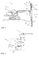
Figure 1 is a schematic side view of a rock drilling rig provided with a drilling unit and a flushing system, -
Figure 2 is a schematic diagram of a flushing system, -
Figure 3 is a schematic diagram of a flushing system provided with means for an air-mist flushing in addition to normal liquid flushing, and -
Figure 4 is a schematic graph showing different control situations of a flushing system. - For the sake of clarity, the figures show some embodiments of the disclosed solution in a simplified manner. In the figures, like reference numerals identify like elements.
-
Figure 1 shows arock drilling rig 1, which comprises amovable carrier 2 and adrilling boom 3 connected movably to thecarrier 2. At a distal end of theboom 3 is adrilling unit 4, which comprises adrilling machine 5. Thedrilling machine 5 may comprise ashank 6 at a front end of therock drilling machine 5 for connecting atool 7. Thetool 7 may comprise one ormore drill rods 8 and adrill bit 9 located at a distal end of thetool 7. Thetool 7 may comprise a flushing channel leading to thedrill bit 9. Thedrilling machine 5 further comprises arotating device 10 for rotating theshank 6 and thetool 7 connected to theshank 6. Thedrilling machine 5 may also be provided with a percussion device for generating impact pulses to thetool 7. Thedrilling unit 4 may further comprise afeed beam 11 on which thedrilling machine 5 may be supported. Thedrilling machine 5 may be moved on thefeed beam 11 by means of afeed device 12. - At a drilling site, one or more drill holes 13 are drilled with the
drilling unit 4. The drill holes 13 may be drilled in a vertical direction, as shown inFigure 1 , or in a horizontal direction. During drilling rock material is detached by means of thedrill bit 9. Produced drilling cuttings needs to be removed from thedrill hole 13. Therefore therock drilling rig 1 is provided with aflushing system 14, which comprises apump unit 15 for feeding pressurized flushing fluid by means of a feed duct orhose 16 to thedrilling machine 5. Thedrilling machine 5 may comprise a flushing housing around theshank 6 so that the flushing fluid may enter to a longitudinal flushing channel of thetool 7. Thus, the flushing fluid may flow through thetool 7 towards thedrill bit 9. Thedrill bit 9 is provided with flushing apertures allowing the flushing fluid to finally escape from of thedrill bit 9. In thedrill hole 13 the flushing fluid pushes the drilling cuttings towards a mouth of thedrill hole 13. During drilling a need for flushing may vary because of executed drilling efficiency or rock material being drilled, for example. Amount of flushing may be adjusted accurately and fast when using flushing system disclosed in this patent application. -
Figure 2 discloses in a simplified manner aflushing system 14 comprising apump unit 15, avalve 17, a flow meter F, afeed duct 16 and a control unit CU. Thepump unit 15 comprises apower device 18, which is arranged to drive apump 19 for producing pressurized flushing fluid flow to thefeed duct 16. Thevalve 17 is arranged in thefeed duct 16 for controlling feeding of the flushing fluid. Thevalve 17 may be on/off type allowing only opening and clos-ing thefeed duct 16. Thevalve 17 is opened when the flushing fluid is fed, and closed when no need for flushing exists. Flow rate of the flushing fluid may be sensed by means of the flow meter F and the sensing data may be transmitted to the control unit CU. Based on the received sensing data the control unit CU may control pumping of the flushing fluid. Thepower device 18 may be a hydraulic motor connected to ahydraulic system 20. Thepumping unit 15 may comprise an adjustingdevice 21 allowing rotational speed of the hydraulic motor and thepump 19 to be adjusted. The control unit CU may control the adjustingdevice 21 and thevalve 17. Alternatively, thepower device 18 may an electrical motor and the adjustingdevice 21 may be a frequency converter. Further, thefeed duct 16 may be provided with an optional pressure sensing device P for detecting prevailing pressure of thefeed duct 16. The pressure sensing data may also be transmitted to the control unit CU. Thanks to the pressure sensing data, it is possible to set the pressure of the flushing fluid as high as tolerated by thedrilling unit 4. The pressure data may also utilized for detecting changes in the rock material being drilled. -
Figure 3 discloses aflushing system 14, which is provided with a liquid flushing system and an air-mist flushing system. The air-mist system comprises acompressor 22, which may be driven by means of apower device 23, such as an electrical motor, hydraulic motor or diesel engine. Supply of pressurized air may be adjusted by means of an adjustingdevice 24, which may be a frequency converter, for example. The produced air flow of thecompressor 22 may be conveyed through anair feed duct 25 to afeed duct 16 wherein the air mixes with the flushing fluid. In the air-mist flushing amount of flushing fluid is smaller than in a normal liquid flushing. A control unit CU may control opening and closing of anair valve 17C, adjustingdevice 24 and a smallsized valve 17A of afeed duct 16a in order to produce desired air-mist flushing. - In
Figure 3 the flushingfluid system 14 comprises twoparallel feed ducts control valves control valves control valve 17A may be utilized in air-mist flushing as disclosed above. Thecontrol valve 17B may be utilized in liquid flushing alone or in combination with thecontrol valve 17A. Thevalves control valves throttles parallel feed ducts control valves pump unit 15. - In
Figure 3 flow rate determination is based on a pressure difference measurement utilizing pressure sensors P1 and P2. Thus, thefeed duct 16 is provided with means for throttling flow of the feed duct. Thethrottle feed duct 16. The adjustingdevice 21 may be controlled on the basis of the detected flow rate. The control unit CU also selects opening and closing ofvalves - The
flushing system 14 may also differ from the one disclosed inFigure 3 . In an alternative solution more than two operationally parallel feed duct portions and valves may be utilized. Further, the flow rate may be detected by means of a flow meter instead of pressure difference measurement. Thepump unit 15 may also be hydraulically driven as it is shown inFigure 2 . -
Figure 4 illustrates three different scales of flows. Reference is made to the flushing system ofFigure 3 comprisingvalves only valve 17A is open, curve in the middle relates to a situation whenonly valve 17B open, and further an uppermost curve A + B shows a situation when bothvalves valves - The drawings and the related description are only intended to illustrate the idea of the invention. In its details, the invention may vary within the scope of the claims.
Claims (15)
- A flushing system of a drilling unit,
wherein the drilling unit (4) comprises a drilling machine (5) and a tool (7) connectable to the drilling machine (5);
and the flushing system (14) comprising:a pump unit (15) for feeding pressurized flushing fluid, wherein the pump unit (15) comprises a pump (19) and a power device (18) for driving the pump (19);at least one feed duct (16) for feeding the pressurized flushing fluid from the pump (19) to the drilling machine (5);at least one valve (17) in the feed duct (16) for controlling flow of the flushing fluid conveyed to the drilling machine (5);at least one sensing device arranged to measure at least one property of the fed flushing fluid;at least one control unit (CU) for controlling the feed of the flushing fluid in response to a sensing data received from the at least one sensing device;characterized in thatthe pump unit (15) is a variable flow rate pump unit (15) provided with adjusting means allowing flow rate of the flushing fluid to be varied; andthe control unit (CU) is configured to determine flow rate of the flushing fluid on the basis of the received sensing data, and the control unit (CU) is further configured to control the flow rate of the fed flushing fluid by adjusting the supplied pressure of the pump (19). - The flushing system as claimed in claim 1, characterized in that
the valve (17) is of on/off -type without adjusting means. - The flushing system as claimed in claim 1 or 2, character-i z e d in that
the control unit (CU) comprises at least one processing device;
the control unit (CU) comprises at least one predetermined control principle for the operation of the flushing system; and
the control unit (CU) is configured to determine control parameters in the processing device on the basis of the received sensing data and the control principle. - The flushing system as claimed in any one of the preceding claims 1 to 3, characterized in that
the flushing system (14) comprises at least a first feed duct (16a) and a second feed duct (16b), which are operationally parallel relative to each other;
the first feed duct (16a) is provided with a first valve (17A) and a first throttle (25a);
the second feed duct (16b) is provided with a second valve (17B) and a second throttle (25b);
the first throttle (25a) and the second throttle (25b) have orifices, which differ in size;
the first valve (17A) and the second valve (17B) are independently controllable; and
the control unit (CU) is configured to control opening and closing of the first valve (17A) and the second valve (17B) according to the operation of the drilling unit (4). - The flushing system as claimed in claim 4, characterized in that
the throttle (25a, 25b) is an integrated element of the valve (17A, 17B). - The flushing system as claimed in claim 4, characterized in that
the throttle (25a, 25b) is a separate element relative to the valve (17A, 17B). - The flushing system as claimed in any one of the preceding claims 1 to 6, characterized in that
at least one throttle (25a, 25b) is arranged in the at least one feed duct (16a, 16b), wherein the throttle (25a, 25b) causes a pressure drop;
the flushing system (14) comprises at least one first pressure sensing device (P1) for detecting pressure of the flushing fluid acting before the throttle (25a, 25b);
the flushing system (14) comprises at least one second pressure sensing device (P2) for detecting pressure of the flushing fluid acting after the throttle (25a, 25b);
the sensed pressure data is transmitted to the control unit (CU);
the control unit (CU) is configured to determine a pressure difference caused by the throttle (25a, 25b); and
the control unit (CU) is further configured to determine the flow rate of the flushing fluid on the basis of the detected pressure difference. - The flushing system as claimed in any one of the preceding claims 1 to 6, characterized in that
the at least one feed duct (16) is provided with at least one flow meter (F) for determining the flow rate of the flushing fluid. - The flushing system as claimed in any one of the preceding claims 1 to 8, characterized in that
the pump (19) is driven by an electrical motor;
operating speed of the pump (19) is adjusted in order to adjust the produced flow of the flushing fluid; and
rotational speed of the electric motor is adjusted by means of an adjusting device (21). - The flushing system as claimed in claim 9, characterized in that
the pump (19) is a fixed displacement pump; and
the supplied pressure of the pump is adjusted by adjusting rotational speed of the pump (19). - The flushing system as claimed in claim 9 or 10, characteri z e d in that
the adjusting device (21) is a frequency converter. - The flushing system as claimed in any one of the preceding claims 1 to 11, characterized in that
at least one pressure sensing device (P) is arranged to detect pressure of the flushing fluid acting in the drilling machine (5);
the pressure of the flushing fluid is adjusted by adjusting the pump (19);
a maximum pressure rate tolerated by the drilling machine (5) is set to the control unit (CU); and
the control unit (CU) is arranged to control the pump unit (15) to supply a pressure close to the predefined maximum pressure. - The flushing system as claimed in any one of the preceding claims 1 to 12, characterized in that
the flushing system (14) is provided with an air-mist flushing system; the flushing system (14) comprises at least one compressor (22) for supplying compressed air for the flushing;
the pump (19) is a water pump arranged to supply pressurized water for the flushing;
the supplied pressurized flushing water and the pressurized flushing air are mixed in the feed duct (16), whereby air-mist is produced; and
the control unit (CU) is arranged to control the operation of the compressor (22). - The flushing system as claimed in claim 13, characteri z e d in that
the compressor (22) is driven by a second electrical motor (23); and operational speed of the second electrical motor (23) is controlled by means of a second frequency converter (24) in order to adjust flow rate of the compressed air. - A method of controlling feeding of flushing fluid of a flushing system of a rock drilling unit,
the rock drilling unit (4) comprising a drilling machine (5) and a tool connectable to the drilling machine (5);
and the method comprises:pressurizing flushing fluid by means of at least one pump unit (15) and conveying the pressurized flushing fluid to the drilling machine (5) through at least one feed duct (16);controlling the feeding of the flushing fluid by means of at least one valve (17) arranged in the feed duct (16);monitoring the fed flushing fluid by means of at least one sensing device; andcontrolling flow rate of the flushing fluid according to the monitoring;characterized bycontrolling flow rate of the flushing fluid by adjusting pressure supplied by the pump unit (15);directing the flushing fluid through at least two valves (17A, 17B) being operationally parallel and having flow paths which are different in size; andselecting opening and closing of the at least two valves (17A, 17B) in response to magnitude of the supplied volume flow of the pump unit (15).
Priority Applications (4)
| Application Number | Priority Date | Filing Date | Title |
|---|---|---|---|
| EP14172341.1A EP2955319A1 (en) | 2014-06-13 | 2014-06-13 | Arrangement and method for feeding flushing fluid |
| AU2015203009A AU2015203009B2 (en) | 2014-06-13 | 2015-06-05 | Arrangement and method for feeding flushing fluid |
| US14/736,384 US20150361743A1 (en) | 2014-06-13 | 2015-06-11 | Arrangement and method for feeding flushing fluid |
| PCT/ZA2015/050001 WO2015192151A2 (en) | 2014-06-13 | 2015-07-07 | Arrangement and method for feeding flushing fluid |
Applications Claiming Priority (1)
| Application Number | Priority Date | Filing Date | Title |
|---|---|---|---|
| EP14172341.1A EP2955319A1 (en) | 2014-06-13 | 2014-06-13 | Arrangement and method for feeding flushing fluid |
Publications (1)
| Publication Number | Publication Date |
|---|---|
| EP2955319A1 true EP2955319A1 (en) | 2015-12-16 |
Family
ID=51162427
Family Applications (1)
| Application Number | Title | Priority Date | Filing Date |
|---|---|---|---|
| EP14172341.1A Withdrawn EP2955319A1 (en) | 2014-06-13 | 2014-06-13 | Arrangement and method for feeding flushing fluid |
Country Status (4)
| Country | Link |
|---|---|
| US (1) | US20150361743A1 (en) |
| EP (1) | EP2955319A1 (en) |
| AU (1) | AU2015203009B2 (en) |
| WO (1) | WO2015192151A2 (en) |
Cited By (3)
| Publication number | Priority date | Publication date | Assignee | Title |
|---|---|---|---|---|
| WO2018060789A1 (en) * | 2016-09-28 | 2018-04-05 | Chetocorporation, S.A. | System and method for operating a cutting machine |
| EP4043153A1 (en) * | 2021-02-11 | 2022-08-17 | Sandvik Mining and Construction Oy | Percussion device and method for controlling the same |
| EP4067615A1 (en) * | 2021-03-31 | 2022-10-05 | Sandvik Mining and Construction Oy | Operating system, rock drilling rig and method |
Families Citing this family (15)
| Publication number | Priority date | Publication date | Assignee | Title |
|---|---|---|---|---|
| MX384893B (en) | 2014-02-28 | 2025-03-04 | Project Phoenix Llc | INTEGRATED PUMP WITH TWO INDEPENDENTLY DRIVEN PRIMARY MOTORS. |
| EP3134648B1 (en) | 2014-04-22 | 2023-06-14 | Project Phoenix, LLC | Fluid delivery system with a shaft having a through-passage |
| US10738799B2 (en) | 2014-06-02 | 2020-08-11 | Project Phoenix, LLC | Linear actuator assembly and system |
| EP3149362B1 (en) | 2014-06-02 | 2019-04-10 | Project Phoenix LLC | Hydrostatic transmission assembly and system |
| MX386246B (en) | 2014-07-22 | 2025-03-04 | Project Phoenix Llc | INTEGRATED EXTERNAL GEAR PUMP WITH TWO INDEPENDENTLY DRIVEN DRIVE MOTORS. |
| EP3467310B1 (en) | 2014-09-23 | 2020-04-22 | Project Phoenix LLC | System to pump fluid and control thereof |
| US10677352B2 (en) | 2014-10-20 | 2020-06-09 | Project Phoenix, LLC | Hydrostatic transmission assembly and system |
| WO2017040792A1 (en) | 2015-09-02 | 2017-03-09 | Project Phoenix, LLC | System to pump fluid and control thereof |
| US11085440B2 (en) * | 2015-09-02 | 2021-08-10 | Project Phoenix, LLC | System to pump fluid and control thereof |
| US10533548B2 (en) | 2016-05-03 | 2020-01-14 | Schlumberger Technology Corporation | Linear hydraulic pump and its application in well pressure control |
| US11525317B2 (en) * | 2020-06-25 | 2022-12-13 | Halliburton Energy Services, Inc. | Open channel flow from multiple pressure sensors |
| TWI826800B (en) | 2020-07-08 | 2023-12-21 | 美商鳳凰計劃股份有限公司 | Dynamic control of gears in a gear pump having a drive-drive configuration |
| EP4179211A1 (en) | 2020-07-08 | 2023-05-17 | Project Phoenix, LLC | Dynamic control of gears in a gear pump having a drive-drive configuration |
| EP4083371B1 (en) * | 2021-04-29 | 2023-11-15 | Sandvik Mining and Construction Oy | Apparatus and method for controlling flushing in rock drilling |
| CN121399348A (en) * | 2023-07-06 | 2026-01-23 | 安百拓凿岩有限公司 | Control system for controlling water flow of autonomous drilling machine |
Citations (6)
| Publication number | Priority date | Publication date | Assignee | Title |
|---|---|---|---|---|
| GB1437442A (en) * | 1973-07-19 | 1976-05-26 | Rock Fall Co Ltd | Flushing system for a drilling machine |
| WO2003071096A1 (en) * | 2002-02-22 | 2003-08-28 | Sandvik Tamrock Oy | Method and arrangement for controlling percussion rock drilling |
| WO2004065761A1 (en) * | 2003-01-24 | 2004-08-05 | Sandvik Tamrock Oy | Hydraulic system for mining equipment and method of adjusting power of rock drill machine |
| WO2007122288A1 (en) * | 2006-04-21 | 2007-11-01 | Sandvik Mining And Construction Oy | Method of controlling operation of rock drilling rig, and rock drilling rig |
| WO2007138170A1 (en) * | 2006-06-01 | 2007-12-06 | Sandvik Mining And Construction Oy | Rock drilling rig and method of controlling thereof |
| US20120048620A1 (en) * | 2010-08-25 | 2012-03-01 | Omron Oilfield & Marine, Inc. | Pressure limiting controller |
Family Cites Families (7)
| Publication number | Priority date | Publication date | Assignee | Title |
|---|---|---|---|---|
| CA2450994C (en) * | 2003-11-27 | 2010-08-10 | Weatherford Canada Ltd. | Method and apparatus to control the rate of flow of a fluid through a conduit |
| FI123650B (en) * | 2007-12-17 | 2013-08-30 | Sandvik Mining & Constr Oy | Rock drilling device and method for drilling rock |
| US20090188721A1 (en) * | 2008-01-30 | 2009-07-30 | Smith Kevin W | Membrane method of making drilling fluids containing microbubbles |
| US8382446B2 (en) * | 2009-05-06 | 2013-02-26 | Baker Hughes Incorporated | Mini-surge cycling method for pumping liquid from a borehole to remove material in contact with the liquid |
| US8757254B2 (en) * | 2009-08-18 | 2014-06-24 | Schlumberger Technology Corporation | Adjustment of mud circulation when evaluating a formation |
| GB2501741B (en) * | 2012-05-03 | 2019-02-13 | Managed Pressure Operations | Method of drilling a subterranean borehole |
| US8789601B2 (en) * | 2012-11-16 | 2014-07-29 | Us Well Services Llc | System for pumping hydraulic fracturing fluid using electric pumps |
-
2014
- 2014-06-13 EP EP14172341.1A patent/EP2955319A1/en not_active Withdrawn
-
2015
- 2015-06-05 AU AU2015203009A patent/AU2015203009B2/en not_active Ceased
- 2015-06-11 US US14/736,384 patent/US20150361743A1/en not_active Abandoned
- 2015-07-07 WO PCT/ZA2015/050001 patent/WO2015192151A2/en not_active Ceased
Patent Citations (6)
| Publication number | Priority date | Publication date | Assignee | Title |
|---|---|---|---|---|
| GB1437442A (en) * | 1973-07-19 | 1976-05-26 | Rock Fall Co Ltd | Flushing system for a drilling machine |
| WO2003071096A1 (en) * | 2002-02-22 | 2003-08-28 | Sandvik Tamrock Oy | Method and arrangement for controlling percussion rock drilling |
| WO2004065761A1 (en) * | 2003-01-24 | 2004-08-05 | Sandvik Tamrock Oy | Hydraulic system for mining equipment and method of adjusting power of rock drill machine |
| WO2007122288A1 (en) * | 2006-04-21 | 2007-11-01 | Sandvik Mining And Construction Oy | Method of controlling operation of rock drilling rig, and rock drilling rig |
| WO2007138170A1 (en) * | 2006-06-01 | 2007-12-06 | Sandvik Mining And Construction Oy | Rock drilling rig and method of controlling thereof |
| US20120048620A1 (en) * | 2010-08-25 | 2012-03-01 | Omron Oilfield & Marine, Inc. | Pressure limiting controller |
Cited By (8)
| Publication number | Priority date | Publication date | Assignee | Title |
|---|---|---|---|---|
| WO2018060789A1 (en) * | 2016-09-28 | 2018-04-05 | Chetocorporation, S.A. | System and method for operating a cutting machine |
| US10877461B2 (en) | 2016-09-28 | 2020-12-29 | Chetocorporation, S.A. | System and method for operating a cutting machine |
| EP4043153A1 (en) * | 2021-02-11 | 2022-08-17 | Sandvik Mining and Construction Oy | Percussion device and method for controlling the same |
| JP2024510378A (en) * | 2021-02-11 | 2024-03-07 | サンドヴィック マイニング アンド コンストラクション オーワイ | Hitting device and method for controlling the hitting device |
| US12345020B2 (en) | 2021-02-11 | 2025-07-01 | Sandvik Mining And Construction Oy | Percussion device and method for controlling the same |
| EP4067615A1 (en) * | 2021-03-31 | 2022-10-05 | Sandvik Mining and Construction Oy | Operating system, rock drilling rig and method |
| WO2022207791A1 (en) * | 2021-03-31 | 2022-10-06 | Sandvik Mining And Construction Oy | Operating system, rock drilling rig and method |
| US12234727B2 (en) | 2021-03-31 | 2025-02-25 | Sandvik Mining And Construction Oy | Operating system, rock drilling rig and method |
Also Published As
| Publication number | Publication date |
|---|---|
| AU2015203009B2 (en) | 2016-05-26 |
| WO2015192151A2 (en) | 2015-12-17 |
| US20150361743A1 (en) | 2015-12-17 |
| WO2015192151A3 (en) | 2016-06-16 |
| AU2015203009A1 (en) | 2016-01-07 |
Similar Documents
| Publication | Publication Date | Title |
|---|---|---|
| US20150361743A1 (en) | Arrangement and method for feeding flushing fluid | |
| CN101427002B (en) | Method of controlling operation of rock drilling rig, and rock drilling rig | |
| US7654337B2 (en) | Arrangement for controlling rock drilling | |
| CA2766303C (en) | Method and apparatus for controlling rock drilling | |
| CN101765694B (en) | Method and device for controlling a rock drilling arrangement | |
| US7934547B2 (en) | Apparatus and methods to control fluid flow in a downhole tool | |
| JP2006510831A5 (en) | ||
| CN103437754A (en) | Pressurization control method and pressurization control system for rotary drilling rig | |
| JP7804696B2 (en) | Apparatus and method for controlling flashing in rock drilling | |
| CN103069101B (en) | Control method and system and the rock drilling equipment of the compressor of rock drilling equipment | |
| SE526462C2 (en) | Procedure, program and arrangement for the control of slag drilling | |
| ZA200503536B (en) | Arrangement for controlling rock drilling | |
| CN102027188B (en) | For monitoring device and the method for the air flowing in rig | |
| WO2007138170A1 (en) | Rock drilling rig and method of controlling thereof | |
| JP4772751B2 (en) | Expansion wing expansion confirmation device for expansion head | |
| CN101213350A (en) | Arrangements for drilling equipment for controlled fluid operation under pressure |
Legal Events
| Date | Code | Title | Description |
|---|---|---|---|
| PUAI | Public reference made under article 153(3) epc to a published international application that has entered the european phase |
Free format text: ORIGINAL CODE: 0009012 |
|
| AK | Designated contracting states |
Kind code of ref document: A1 Designated state(s): AL AT BE BG CH CY CZ DE DK EE ES FI FR GB GR HR HU IE IS IT LI LT LU LV MC MK MT NL NO PL PT RO RS SE SI SK SM TR |
|
| AX | Request for extension of the european patent |
Extension state: BA ME |
|
| 17P | Request for examination filed |
Effective date: 20160616 |
|
| RBV | Designated contracting states (corrected) |
Designated state(s): AL AT BE BG CH CY CZ DE DK EE ES FI FR GB GR HR HU IE IS IT LI LT LU LV MC MK MT NL NO PL PT RO RS SE SI SK SM TR |
|
| STAA | Information on the status of an ep patent application or granted ep patent |
Free format text: STATUS: THE APPLICATION IS DEEMED TO BE WITHDRAWN |
|
| 18D | Application deemed to be withdrawn |
Effective date: 20180103 |