EP2955101A1 - Ventilated drainage system - Google Patents
Ventilated drainage system Download PDFInfo
- Publication number
- EP2955101A1 EP2955101A1 EP15165610.5A EP15165610A EP2955101A1 EP 2955101 A1 EP2955101 A1 EP 2955101A1 EP 15165610 A EP15165610 A EP 15165610A EP 2955101 A1 EP2955101 A1 EP 2955101A1
- Authority
- EP
- European Patent Office
- Prior art keywords
- housing
- fluid
- drainage tube
- aircraft
- drainage
- Prior art date
- Legal status (The legal status is an assumption and is not a legal conclusion. Google has not performed a legal analysis and makes no representation as to the accuracy of the status listed.)
- Granted
Links
Images







Classifications
-
- F—MECHANICAL ENGINEERING; LIGHTING; HEATING; WEAPONS; BLASTING
- F15—FLUID-PRESSURE ACTUATORS; HYDRAULICS OR PNEUMATICS IN GENERAL
- F15D—FLUID DYNAMICS, i.e. METHODS OR MEANS FOR INFLUENCING THE FLOW OF GASES OR LIQUIDS
- F15D1/00—Influencing flow of fluids
- F15D1/001—Flow of fluid from conduits such as pipes, sleeves, tubes, with equal distribution of fluid flow over the evacuation surface
-
- B—PERFORMING OPERATIONS; TRANSPORTING
- B64—AIRCRAFT; AVIATION; COSMONAUTICS
- B64C—AEROPLANES; HELICOPTERS
- B64C1/00—Fuselages; Constructional features common to fuselages, wings, stabilising surfaces or the like
- B64C1/14—Windows; Doors; Hatch covers or access panels; Surrounding frame structures; Canopies; Windscreens accessories therefor, e.g. pressure sensors, water deflectors, hinges, seals, handles, latches, windscreen wipers
- B64C1/1407—Doors; surrounding frames
- B64C1/1453—Drain masts
-
- B—PERFORMING OPERATIONS; TRANSPORTING
- B64—AIRCRAFT; AVIATION; COSMONAUTICS
- B64D—EQUIPMENT FOR FITTING IN OR TO AIRCRAFT; FLIGHT SUITS; PARACHUTES; ARRANGEMENT OR MOUNTING OF POWER PLANTS OR PROPULSION TRANSMISSIONS IN AIRCRAFT
- B64D29/00—Power-plant nacelles, fairings or cowlings
-
- B—PERFORMING OPERATIONS; TRANSPORTING
- B64—AIRCRAFT; AVIATION; COSMONAUTICS
- B64D—EQUIPMENT FOR FITTING IN OR TO AIRCRAFT; FLIGHT SUITS; PARACHUTES; ARRANGEMENT OR MOUNTING OF POWER PLANTS OR PROPULSION TRANSMISSIONS IN AIRCRAFT
- B64D37/00—Arrangements in connection with fuel supply for power plant
- B64D37/005—Accessories not provided for in the groups B64D37/02 - B64D37/28
-
- B—PERFORMING OPERATIONS; TRANSPORTING
- B64—AIRCRAFT; AVIATION; COSMONAUTICS
- B64D—EQUIPMENT FOR FITTING IN OR TO AIRCRAFT; FLIGHT SUITS; PARACHUTES; ARRANGEMENT OR MOUNTING OF POWER PLANTS OR PROPULSION TRANSMISSIONS IN AIRCRAFT
- B64D37/00—Arrangements in connection with fuel supply for power plant
- B64D37/02—Tanks
- B64D37/14—Filling or emptying
- B64D37/20—Emptying systems
- B64D37/26—Jettisoning of fuel
-
- F—MECHANICAL ENGINEERING; LIGHTING; HEATING; WEAPONS; BLASTING
- F01—MACHINES OR ENGINES IN GENERAL; ENGINE PLANTS IN GENERAL; STEAM ENGINES
- F01D—NON-POSITIVE DISPLACEMENT MACHINES OR ENGINES, e.g. STEAM TURBINES
- F01D25/00—Component parts, details, or accessories, not provided for in, or of interest apart from, other groups
- F01D25/32—Collecting of condensation water; Drainage ; Removing solid particles
-
- F—MECHANICAL ENGINEERING; LIGHTING; HEATING; WEAPONS; BLASTING
- F02—COMBUSTION ENGINES; HOT-GAS OR COMBUSTION-PRODUCT ENGINE PLANTS
- F02K—JET-PROPULSION PLANTS
- F02K1/00—Plants characterised by the form or arrangement of the jet pipe or nozzle; Jet pipes or nozzles peculiar thereto
- F02K1/78—Other construction of jet pipes
- F02K1/82—Jet pipe walls, e.g. liners
-
- F—MECHANICAL ENGINEERING; LIGHTING; HEATING; WEAPONS; BLASTING
- F15—FLUID-PRESSURE ACTUATORS; HYDRAULICS OR PNEUMATICS IN GENERAL
- F15D—FLUID DYNAMICS, i.e. METHODS OR MEANS FOR INFLUENCING THE FLOW OF GASES OR LIQUIDS
- F15D1/00—Influencing flow of fluids
- F15D1/002—Influencing flow of fluids by influencing the boundary layer
- F15D1/0065—Influencing flow of fluids by influencing the boundary layer using active means, e.g. supplying external energy or injecting fluid
- F15D1/008—Influencing flow of fluids by influencing the boundary layer using active means, e.g. supplying external energy or injecting fluid comprising fluid injection or suction means
-
- F—MECHANICAL ENGINEERING; LIGHTING; HEATING; WEAPONS; BLASTING
- F05—INDEXING SCHEMES RELATING TO ENGINES OR PUMPS IN VARIOUS SUBCLASSES OF CLASSES F01-F04
- F05D—INDEXING SCHEME FOR ASPECTS RELATING TO NON-POSITIVE-DISPLACEMENT MACHINES OR ENGINES, GAS-TURBINES OR JET-PROPULSION PLANTS
- F05D2260/00—Function
- F05D2260/60—Fluid transfer
- F05D2260/602—Drainage
-
- Y—GENERAL TAGGING OF NEW TECHNOLOGICAL DEVELOPMENTS; GENERAL TAGGING OF CROSS-SECTIONAL TECHNOLOGIES SPANNING OVER SEVERAL SECTIONS OF THE IPC; TECHNICAL SUBJECTS COVERED BY FORMER USPC CROSS-REFERENCE ART COLLECTIONS [XRACs] AND DIGESTS
- Y02—TECHNOLOGIES OR APPLICATIONS FOR MITIGATION OR ADAPTATION AGAINST CLIMATE CHANGE
- Y02T—CLIMATE CHANGE MITIGATION TECHNOLOGIES RELATED TO TRANSPORTATION
- Y02T50/00—Aeronautics or air transport
- Y02T50/60—Efficient propulsion technologies, e.g. for aircraft
-
- Y—GENERAL TAGGING OF NEW TECHNOLOGICAL DEVELOPMENTS; GENERAL TAGGING OF CROSS-SECTIONAL TECHNOLOGIES SPANNING OVER SEVERAL SECTIONS OF THE IPC; TECHNICAL SUBJECTS COVERED BY FORMER USPC CROSS-REFERENCE ART COLLECTIONS [XRACs] AND DIGESTS
- Y10—TECHNICAL SUBJECTS COVERED BY FORMER USPC
- Y10T—TECHNICAL SUBJECTS COVERED BY FORMER US CLASSIFICATION
- Y10T137/00—Fluid handling
- Y10T137/0318—Processes
- Y10T137/0391—Affecting flow by the addition of material or energy
-
- Y—GENERAL TAGGING OF NEW TECHNOLOGICAL DEVELOPMENTS; GENERAL TAGGING OF CROSS-SECTIONAL TECHNOLOGIES SPANNING OVER SEVERAL SECTIONS OF THE IPC; TECHNICAL SUBJECTS COVERED BY FORMER USPC CROSS-REFERENCE ART COLLECTIONS [XRACs] AND DIGESTS
- Y10—TECHNICAL SUBJECTS COVERED BY FORMER USPC
- Y10T—TECHNICAL SUBJECTS COVERED BY FORMER US CLASSIFICATION
- Y10T137/00—Fluid handling
- Y10T137/206—Flow affected by fluid contact, energy field or coanda effect [e.g., pure fluid device or system]
- Y10T137/2082—Utilizing particular fluid
Definitions
- the present disclosure relates generally to draining fluids and, in particular, to draining fluids from a structure on a mobile platform. Still more particularly, the present disclosure relates to a method and apparatus for draining fluid away from the structure during various stages of operation of the mobile platform.
- Drainage systems are often used to drain fluids from mobile platforms.
- a drainage system may be used to drain fluids from an aircraft during operation of the aircraft.
- a drainage system may be used to drain leaking fuel, hydraulic fluid, water, or other types of fluids from the structure. These drainage systems are employed to dispose of unneeded fluids and prevent undesired contact between the drained fluids and the mobile platform.
- Some drainage systems include a drainage tube extending from the outer surface of the structure.
- the length, size, and shape of the drainage tube may be altered to modify the amount of fluid drained from the tube. For instance, the size of an opening in the tube may be increased to increase the amount of fluid drained from the tube. Gravity causes the fluid to flow out of the structure, through the drainage tube, and into the environment surrounding the mobile platform.
- the forward motion of the mobile platform may force the fluid draining from the drainage tube back onto the structure.
- Contact between the drained fluid and the mobile platform may be undesirable in some instances. For example, re-entry of fluids into an aircraft engine may degrade performance of the engine. Some fluids may cause inconsistencies in the paint on the structure. These inconsistencies may reduce the aesthetics of the structure and may result in repainting of portions of the structure.
- the drainage tube may be lengthened to provide a desired drainage path for the fluid. Shields also may be placed over the drainage tube to reduce back splatter of the fluid onto the mobile platform. These modifications, however, may increase the weight of the drainage system more than desired and increase the drag of the mobile platform.
- an apparatus comprises a drainage tube, a housing, a number of inlet holes in the housing, and a number of outlet holes in the housing.
- the drainage tube has first end that connects to a structure on a mobile platform and a second end opposite the first end.
- the housing also connects to the structure.
- the drainage tube is located within the housing. Air flows into the housing, during movement of the mobile platform, through the number of inlet holes in the housing. The air flows out of the housing, during the movement of the mobile platform, through the number of outlet holes. The air flowing into the housing through the number of inlet holes and out of the housing through the number of outlet holes directs fluid out of the drainage tube and away from the structure during the movement of the aircraft.
- a method of draining fluid from a structure on a mobile platform Air moves through a number of inlet holes into a housing of a drainage system connected to the structure. The air circulates within the housing. The air moves through a number of outlet holes in the housing. The fluid drains from a drainage tube located in the housing. The air flowing into the housing through the number of inlet holes and out the housing through the number of outlet holes directs the fluid out of the drainage tube and away from the structure during movement of the mobile platform.
- a drainage system for a structure on an aircraft comprises a drainage tube, a housing, a number of inlet holes, and a number of outlet holes.
- the drainage tube is physically associated with the structure.
- the drainage tube drains a fluid from the structure.
- the housing is physically associated with the structure.
- the drainage tube is located within the housing.
- the number of inlet holes is located on a leading edge of the housing. Air flows into the housing through the number of inlet holes during flight of the aircraft. The air flows out of the housing during flight of the aircraft through the number of outlet holes. The air flowing into the housing through the number of inlet holes and out of the housing through the number of outlet holes directs the fluid out of the drainage tube and away from the structure such that splatter of the fluid on the aircraft is reduced.
- the invention can involve an apparatus that may include a drainage tube (210) having a first end (213) that connects to a structure (206) on a mobile platform (201) and a second end (214) opposite the first end (213); a housing (212) that connects to the structure (206), wherein the drainage tube (210) is located within the housing (212); a number of inlet holes (226) in the housing (212) though which air (230) flows into the housing (212) during movement of the mobile platform (201); and a number of outlet holes (228) in the housing (212) through which the air (230) flows out of the housing (212) during the movement of the mobile platform (201), wherein the air (230) flowing into the housing (212) through the number of inlet holes (226) and out of the housing (212) through the number of outlet holes (228) directs fluid (204) out of the drainage tube (210) and away from the structure (206) during the movement of the mobile platform (201).
- a drainage tube (210) having a first end (213) that connects to a
- the air (230) flowing into the housing (212) through the number of inlet holes (226) and out of the housing (212) through the number of outlet holes (228) may direct the fluid (204) out of the drainage tube (210) and away from the structure (206) such that splatter of the fluid (204) on the mobile platform (201) is reduced. This will enhance performance and efficiency.
- the drainage tube (210) may drain the fluid (204) from the structure (206) and can include a second drainage tube located within the housing (212), wherein the second drainage tube drains the fluid (204) from the structure (206).
- the apparatus can also include a nozzle (246) connected to the housing (212) and covering the number of outlet holes (228), wherein the nozzle (246) directs the fluid (204) draining from the drainage tube (210) away from the structure (206).
- the number of inlet holes (226) may be located on a leading edge (238) of the housing (212).
- the structure (206) may be selected from one of a skin panel, a wing, a compartment, a tank, a drive system, a control surface, a nacelle, a power supply system, a wheel-well blister, a window, and a windshield.
- the drainage tube (210) may be physically associated with the housing (212).
- the housing (212) may have a shape (234) that reduces drag on the housing (212) during the movement of the mobile platform (201).
- the drainage tube (210) and the housing (212) may form a drainage system (202) for the structure (206) that reduces re-entry (224) of the fluid (204) into the structure (206).
- the invention can involve a method of draining fluid (204) from a structure (206) on a mobile platform (201) that may include moving (1300) air (230) through a number of inlet holes (226) into a housing (212) of a drainage system (202) connected to the structure (206), wherein the air (230) circulates within the housing (212); moving (1302) the air (230) through a number of outlet holes (228) in the housing (212); and draining (1304) the fluid (204) from a drainage tube (210) located in the housing (212), wherein the air (230) flowing into the housing (212) through the number of inlet holes (226) and out the housing (212) through the number of outlet holes (228) directs the fluid (204) out of the drainage tube (210) and away from the structure (206) during movement of the mobile platform (201).
- Moving the air (230) into the housing (212) through the number of inlet holes (226) and out of the housing (212) through the number of outlet holes (228) may direct the fluid (204) out of the drainage tube (210) and away from the structure (206) such that splatter of the fluid (204) on the mobile platform (201) is reduced.
- the method may also include directing the fluid (204) from the drainage tube (210) through a nozzle (246) connected to the housing (212), wherein the fluid (204) flows away from the structure (206).
- the drainage tube may drain the fluid (204) from a second drainage tube located in the housing (212).
- the method may also include forming the number of inlet holes (226) in a leading edge (238) of the housing (212).
- the method may also include forming the housing (212) with an aerodynamic shape (236) configured to reduce drag on the housing (212) during the movement of the mobile platform (201).
- the invention can involve a drainage system (202) for a structure (206) of an engine (110) on an aircraft (208) that may include a drainage tube (210) physically associated with the structure (206) that drains a fluid (204) from the structure (206); a housing (212) physically associated with the structure (206), wherein the drainage tube (210) is located within the housing (212); a number of inlet holes (226) located on a leading edge (238) of the housing (212), wherein air (230) flows into the housing (212) through the number of inlet holes (226) during flight of the aircraft (208); and a number of outlet holes (228) in the housing (212) through which the air (230) flows out of the housing (212) during the flight of the aircraft (208), wherein the air (230) flowing into the housing (212) through the number of inlet holes (226) and out of the housing (212) through the number of outlet holes (228) directs the fluid (204) out of the drainage tube (210) and away from the structure (206) such that splatter of the fluid (204) on
- the drainage system may reduces re-entry (224) of the fluid (204) into the structure (206).
- the drainage system (202) of claim 16 may also include a nozzle (246) connected to the housing (212), wherein the nozzle (246) directs the fluid (204) draining from the drainage tube (210) away from the structure (206).
- the drainage tube (210) may be a first drainage tube and may also include a second drainage tube located within the housing (212), wherein the second drainage tube drains the fluid (204) from the structure (206).
- a particular shape (234) of the number of inlet holes (226) may be selected to provide a desired drainage path (221) for the fluid (204) during the flight of the aircraft (208). These characteristics can improve performance and operational efficiency of the drainage system.
- the illustrative embodiments recognize and take into account one or more different considerations. For example, the illustrative embodiments recognize and take into account that it may be desirable to have a drainage system for a mobile platform that reduces splatter of drained fluid back onto the mobile platform. This mobile platform may be, for example, without limitation, an aircraft. The illustrative embodiments recognize and take into account that the drainage system must reduce this back splatter to within selected tolerances in order to pass various drainage certification tests for the mobile platform. A failed drainage certification test results in costly rework and modification of the drainage system to achieve compliance with certification requirements.
- the illustrative embodiments recognize and take into account that compliance with certification requirements often requires manufacturers to lengthen the drainage system to ensure the fluid flows away from the mobile platform in a desired manner. However, making such modifications to the drainage system increases the overall weight and complexity of the mobile platform. The illustrative embodiments further recognize and take into account that adding heavy components to the drainage tube or lengthening the drainage tube increases drag, which reduces the overall aerodynamic performance of the mobile platform.
- a lengthened drainage tube may scrape the ground during operation of the mobile platform, contact objects underneath the aircraft during ground operation, or both.
- a lengthened tube may scrape the ground during takeoff.
- An apparatus comprises a drainage tube, a housing, a number of inlet holes in the housing, and a number of outlet holes in the housing.
- the drainage tube has a first end that connects to the structure on the mobile platform and a second end having an opening.
- the housing also connects to the structure.
- the drainage tube is located within the housing. Air flows into the housing during movement of the mobile platform through the number of inlet holes in the housing. The air flows out of the housing during the movement of the mobile platform through the number of outlet holes. The air flowing into the housing through the number of inlet holes, through the housing, and out of the housing through the number of outlet holes directs fluid out of the drainage tube and away from the structure during the movement of the mobile platform.
- aircraft 100 has wing 102 and wing 104 attached to fuselage 106.
- Aircraft 100 includes engine 108 attached to wing 102 and engine 110 attached to wing 104.
- Fuselage 106 has tail section 112. Horizontal stabilizer 114 , horizontal stabilizer 116 , and vertical stabilizer 118 are attached to tail section 112 of fuselage 106.
- Aircraft 100 is an example of a mobile platform in which a drainage system in accordance with an illustrative embodiment may be implemented to drain fluids.
- drainage system 120 is used to drain fluid from engine 110 in aircraft 100. Drainage system 120 extending outward from nacelle 122 of engine 110 is shown in section 124.
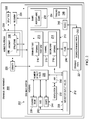
- Drainage environment 200 is an example of an environment in which drainage system 202 is used to drain fluid 204 from structure 206.
- Drainage system 120 in Figure 1 is an example of a physical implementation for drainage system 202 shown in block form in this figure.
- drainage system 202 is connected to structure 206 to prevent fluid 204 from collecting in structure 206.
- fluid 204 is liquid that is unneeded for operation of structure 206.
- fluid 204 may be fluid leaking from components within structure 206.
- fluid 204 may be condensation formed on a surface of structure 206.
- fluid 204 may be normal fluid loss from a mechanical system housed within structure 206.
- Fluid 204 may comprise at least one of oil, water, a hydraulic fluid, fuel, a coolant, or some other type of fluid in this illustrative example.
- the phrase "at least one of,” when used with a list of items, means different combinations of one or more of the listed items may be used and only one of the items in the list may be needed.
- the item may be a particular object, thing, or category.
- "at least one of” means any combination of items or number of items may be used from the list, but not all of the items in the list may be required.
- “at least one of item A, item B, and item C” may mean item A; item A and item B; item B; item A, item B, and item C; or item B and item C.
- “at least one of item A, item B, and item C” may mean, for example, without limitation, two of item A, one of item B, and ten of item C; four of item B and seven of item C; or some other suitable combination.
- fluid 204 may collect within structure 206.
- fluid 204 within structure 206 may decrease the efficiency of structure 206 , corrode structure 206 , or otherwise become undesirable.
- structure 206 may take various forms.
- structure 206 may be selected from one of a skin panel, a wing, a compartment, a tank, a drive system, a control surface, a nacelle, a power supply system, a wheel-well blister, a window, a windshield, and other suitable types of structures.
- structure 206 is physically associated with mobile platform 201.
- a first component, structure 206 is considered to be physically associated with a second component, mobile platform 201 , by being secured to the second component, bonded to the second component, mounted to the second component, welded to the second component, fastened to the second component, and/or connected to the second component in some other suitable manner.
- the first component also may be connected to the second component using a third component.
- the first component may also be considered to be physically associated with the second component by being formed as part of the second component, an extension of the second component, or both.
- mobile platform 201 takes the form of aircraft 208.
- Aircraft 100 shown in Figure 1 is an example of a physical implementation of aircraft 208 shown in block form in this figure.
- mobile platform 201 may take other forms.
- mobile platform 201 may be a surface ship, a tank, a personnel carrier, a train, an automobile, and other suitable platforms. In this manner, mobile platform 201 may be a vehicle.
- drainage system 202 extends outward from structure 206 to drain fluid 204 from the interior of structure 206 into the environment around structure 206.
- Drainage system 202 comprises a number of components.
- drainage system 202 includes drainage tube 210 and housing 212. Drainage tube 210 is an object that drains fluid 204 from structure 206.
- drainage tube 210 has first end 213 , second end 214 opposite first end 213 , and channel 215.
- First end 213 of drainage tube 210 has opening 216.
- Second end 214 of drainage tube 210 has opening 218.
- first end 213 of drainage tube 210 is connected to structure 206 on aircraft 208.
- Drainage tube 210 is in fluid communication with structure 206 at first end 213. Drainage tube 210 is also in fluid communication with the environment surrounding structure 206 at second end 214.
- a component is in fluid communication with another component when a fluid may flow from one component to another component.
- fluid 204 flows from structure 206 through opening 216 in first end 213 of drainage tube 210 , through channel 215 , and out opening 218 in second end 214.
- Gravity 220 causes fluid 204 to flow through drainage tube 210 in this manner.
- splatter 222 refers to a splash of fluid 204 that contacts one or more structures in aircraft 208.
- splatter 222 occurs when fluid 204 from drainage tube 210 splashes onto a skin panel in aircraft 208.
- the forward motion of aircraft 208 during flight also may cause re-entry 224 of fluid 204 into structure 206.
- Re-entry 224 of fluid 204 occurs when fluid 204 previously drained from structure 206 is re-ingested by structure 206.
- re-entry 224 of fluid 204 occurs when fluid 204 previously drained from engine 110 in Figure 1 re-enters engine 110.
- Both splatter 222 and re-entry 224 of fluid 204 are undesirable in this illustrative example. At least one of splatter 222 or re-entry 224 of fluid 204 may degrade performance of aircraft 208 , corrode structure 206 , cause structure 206 to fail, or a combination thereof.
- housing 212 is placed over drainage tube 210 such that drainage tube 210 is located within housing 212.
- Housing 212 is a structure that covers drainage tube 210. In some cases, housing 212 may be referred to as a shield for drainage tube 210.
- Housing 212 is connected to structure 206 in this illustrative example. In some cases, drainage tube 210 is physically associated with housing 212.
- housing 212 includes number of inlet holes 226 and number of outlet holes 228.
- a "number of" items is one or more items.
- number of inlet holes 226 includes one or more inlet holes.
- air 230 flows into housing 212 through number of inlet holes 226 during flight of aircraft 208. Air 230 circulates through housing 212 and flows out of housing 212 through number of outlet holes 228. In this manner, number of inlet holes 226 provides ventilation 232 for housing 212.
- housing 212 to drainage tube 210 directs fluid 204 away from aircraft 208 without lengthening drainage tube 210.
- air 230 flowing into housing 212 through number of inlet holes 226 and out of housing 212 through number of outlet holes 228 directs fluid 204 out of drainage tube 210 and away from structure 206 during flight of aircraft 208.
- This flow of air 230 through housing 212 results in desired drainage path 233 for fluid 204.
- Desired drainage path 233 is a path for drainage of fluid 204 that reduces splatter 222 of fluid 204 on aircraft 208.
- Re-entry 224 of fluid 204 into structure 206 is also reduced or eliminated when fluid 204 has desired drainage path 233.
- housing 212 has shape 234.
- Shape 234 is a configuration for housing 212 that reduces drag on housing 212 during flight of aircraft 208. In this manner, shape 234 is aerodynamic shape 236 for housing 212.
- housing 212 has leading edge 238 and trailing edge 240.
- Leading edge 238 is the portion of housing 212 that first contacts the air.
- leading edge 238 is the forward portion of housing 212.
- Trailing edge 240 is the portion of housing 212 opposite leading edge 238.
- aerodynamic shape 236 of housing 212 may be formed such that leading edge 238 is wider than trailing edge 240.
- Number of inlet holes 226 is located on leading edge 238 of housing 212.
- size 242 and shape 244 of number of inlet holes 226 , number of outlet holes 228 , or both may be designed such that a desired amount of air 230 , flow of air 230 , or both travel through housing 212.
- size 242 of each of number of inlet holes 226 may be increased to increase the amount of air 230 entering housing 212.
- size 242 of number of outlet holes 228 may be reduced to increase the speed at which air 230 flows out of housing 212.
- size 242 refers to the dimensions of number of inlet holes 226.
- size 242 may be the diameter of a circular hole.
- Shape 244 may be selected from one of a circular shape, an oblong shape, a hexagonal shape, a square shape, a rectangular shape, an irregular shape, or other suitable shapes.
- nozzle 246 may be connected to housing 212. Nozzle 246 may cover number of outlet holes 228. Nozzle 246 is a device that further directs fluid 204 and air 230 away from structure 206. In an illustrative example, nozzle 246 provides more precise direction of fluid 204 and air 230 than open outlet holes.
- Housing 212 is configured to direct fluid 204 away from aircraft 208 without adding undesired weight to aircraft 208.
- housing 212 may be formed from lighter weight materials than some currently used systems. These materials may include, for example, without limitation, composite material, aluminum, titanium, corrosion resistant steel, and other suitable materials. Lightweight materials may be selected for housing 212 since housing 212 does not need to withstand external loads. Housing 212 encounters only aero loads in this illustrative example.
- drainage system 202 in Figure 2 is not meant to imply physical or architectural limitations to the manner in which an illustrative embodiment may be implemented.
- Other components in addition to or in place of the ones illustrated may be used. Some components may be optional.
- the blocks are presented to illustrate some functional components. One or more of these blocks may be combined, divided, or combined and divided into different blocks when implemented in an illustrative embodiment.
- drainage system 202 may include more than one drainage tube.
- drainage tube 210 is a first drainage tube.
- a second drainage tube also may be located within housing 212. The second drainage tube may drain fluid 204 from structure 206 , structures adjacent to structure 206 , or a combination thereof.
- an illustrative embodiment may be implemented in other platforms that have fluid drainage concerns.
- the fluid dynamics of an illustrative embodiment are operable to prevent back splatter and re-entry as long as fluid flows through the inlet holes and out of the outlet holes.
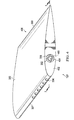
- FIG. 3 an illustration of a drainage system on a nacelle for an aircraft engine is depicted in accordance with an illustrative embodiment.
- Section 124 with drainage system 120 extending outward from nacelle 122 for engine 110 of aircraft 100 from Figure 1 is shown in this view.
- Engine 110 is an example of a physical implementation for structure 206 shown in block form in Figure 2.
- drainage system 120 includes housing 300 and drainage tube 302 located within housing 300.
- Housing 300 is connected to nacelle 122.
- housing 300 and drainage tube 302 are physically associated with nacelle 122.
- Housing 300 has inlet holes 304 and outlet hole 306.
- Inlet holes 304 are located on leading edge 307 of housing 300 in this illustrative example. Specifically, inlet holes 304 are located on the lower half of leading edge 307. Trailing edge 308 is located opposite leading edge 307.
- air 310 enters housing 300 through inlet holes 304 and exits housing 300 through outlet hole 306. In this manner, air 310 circulates within housing 300 during flight of aircraft 100.
- FIG. 4 an illustration of a drainage system for a nacelle is depicted in accordance with an illustrative embodiment.
- an enlarged bottom view of drainage system 120 is shown in the direction of lines 4-4 in Figure 3.
- a portion of drainage tube 302 extends through outlet hole 306.
- end 400 of drainage tube 302 is substantially flush with bottom surface 402 of housing 300.
- end 400 of drainage tube 302 may extend slightly outward from bottom surface 402 of housing 300 or may be shorter than housing 300 , depending on the particular implementation.
- bottom surface 402 may be omitted from the design of housing 300.
- drainage tube 302 has opening 404. Fluid drains from drainage tube 302 through opening 404.
- housing 300 of drainage system 120 has aerodynamic shape 406. Aerodynamic shape 406 is designed such that leading edge 307 of housing 300 is wider than trailing edge 308 of housing 300. The width of housing 300 tapers in the direction of trailing edge 308 to reduce drag on housing 300.
- FIG. 5 an illustration of a cross-sectional view of a drainage system for a nacelle is depicted in accordance with an illustrative embodiment.
- a cross-sectional view of drainage system 120 taken along lines 5-5 in Figure 4 is shown.
- Chamber 500 is seen in this view. Chamber 500 is a space within housing 300 that surrounds drainage tube 302. Air 310 as shown in Figure 3 circulates through chamber 500 in this illustrative example.
- FIG. 6 an illustration of a side view of a drainage system for a nacelle is depicted in accordance with an illustrative embodiment.
- a side view of drainage system 120 is shown in the direction of lines 6-6 in Figure 3 .
- Housing 300 is shown in phantom such that drainage tube 302 is seen in greater detail.
- end 600 of drainage tube 302 is connected to nacelle 122.
- End 600 also has an opening (not shown in this view) through which fluid 602 flows. Fluid 602 flows from end 600 , through drainage tube 302 , and out opening 404 into the environment around nacelle 122.
- drainage tube 302 drains fluid 602 out of nacelle 122 in the direction of arrow 604. Gravity assists in draining fluid 602. As aircraft 100 picks up speed, gravity is insufficient to prevent fluid 602 from splattering back on nacelle 122 or re-entering nacelle 122. The air flowing from housing 300 reduces such splatter and re-entry to fall within selected tolerances.
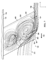
- Figures 7-8 show illustrations of air 310 flowing within housing 300 of drainage system 120 from Figure 6 during flight of an aircraft at different speeds. Figures 7-8 also depict the drainage path for fluid 602 directed by the flow of air 310 exiting housing 300. These figures show some examples of the path of air 310 flowing inside of housing 300. In particular, air 310 circulates through housing 300 and out of housing 300 in the direction of arrow 704.
- Air 310 flows into housing 300 through inlet holes 304 and circulates within chamber 500 , shown in Figure 5 , in housing 300. A portion of air 310 then flows out of housing 300 through outlet hole 306. The flow of air 310 directs fluid 602 away from nacelle 122 to reduce or eliminate splatter or re-entry. Drainage path 708 of fluid 602 is shown in this view along with ventilation from air 310.
- aircraft 100 is traveling in the direction of arrow 706 at a second speed that is faster than the speed of aircraft 100 shown in Figure 7.
- Fluid 602 has drainage path 800 in this illustrative example. Air 310 flowing out of housing 300 through outlet hole 306 directs fluid 602 away from nacelle 122 along drainage path 800. In this manner, drainage system 120 reduces or eliminates splatter and re-entry of fluid at various speeds of aircraft 100.
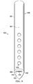
- FIG. 9 an illustration of a front view of a drainage system for a nacelle is depicted in accordance with an illustrative embodiment.
- a front view of drainage system 120 is shown in the direction of lines 9-9 in Figure 3.
- the size and shape of inlet holes 304 is shown in this view.
- inlet holes 304 are located equidistant from one another.
- each of inlet holes 304 has the same shape.
- inlet holes 304 may have different shapes and locations on leading edge 307. Inlet holes 304 intercept a high total pressure in this illustrative example.
- Figures 10-11 are illustrations of drainage system 120 as shown in Figure 9.
- Figures 10-11 show air 310 flowing out of housing 300 of drainage system 120 during flight of aircraft 100 at different speeds.
- Figures 10-11 also depict the manner in which fluid 602 flows out of drainage tube 302 and away from nacelle 122.
- aircraft 100 is again traveling at the slower speed.
- the flow of air 310 out of housing 300 first directs fluid 602 downward before fluid 602 is expelled in the opposite direction of travel of aircraft 100.
- fluid 602 is directed downward and away from nacelle 122 as air 310 flows through housing 300 from inlet holes 304 and out of outlet hole 306.
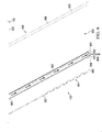
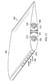
- Drainage system 1200 is an example of an implementation for drainage system 202 attached to an aircraft structure shown in block form in Figure 2.
- drainage system 1200 includes housing 1202 , drainage tube 1204 , and drainage tube 1206.
- Drainage tube 1204 has opening 1208 and drainage tube 1206 has opening 1210.
- drainage tube 1204 and drainage tube 1206 drain fluid (not shown in this view) from one or more aircraft structures.
- Housing 1202 of drainage system 1200 has inlet holes 1212 , outlet hole 1213 , and outlet hole 1214 in this illustrative example. Air 1216 flows into housing 1202 through inlet holes 1212 and out of housing 1202 through outlet hole 1213 and outlet hole 1214.
- air 1216 flowing out of outlet hole 1213 directs fluid draining from drainage tube 1204 away from the aircraft.
- air 1216 flowing out of outlet hole 1214 directs fluid draining from drainage tube 1206 away from the aircraft.
- housing 1202 reduces or eliminates splatter of the fluid back onto the aircraft, re-entry of the fluid into aircraft structures, or both.
- outlet holes Although two outlet holes are shown in this illustrative example, other numbers of outlet holes may be present in an illustrative embodiment. For example, without limitation, three holes, five holes, ten holes, or some other suitable number of outlet holes may be present in housing 1202.
- drainage tube 1204 and drainage tube 1206 may share the same outlet hole.
- a single outlet hole may have an oblong shape.
- the entire bottom portion of housing 1202 may be open.
- drainage system 120 and drainage system 1200 in Figure 1 and Figures 3-12 are not meant to imply physical or architectural limitations to the manner in which an illustrative embodiment may be implemented.
- Other components in addition to or in place of the ones illustrated may be used. Some components may be optional.
- Figure 1 and Figures 3-12 may be illustrative examples of how components shown in block form in Figure 2 can be implemented as physical structures. Additionally, some of the components in Figure 1 and Figures 3-12 may be combined with components in Figure 2 , used with components in Figure 2 , or a combination of the two.
- FIG. 13 an illustration of a flowchart of a process for draining fluid from a structure on an aircraft is depicted in accordance with an illustrative embodiment.
- the process illustrated in Figure 13 may be implemented using drainage system 202 for structure 206 during flight of aircraft 208 in Figure 2.
- the process begins by moving air through a number of inlet holes into a housing of a drainage system connected to the structure such that the air circulates within the housing (operation 1300 ). Next, the process moves the air through a number of outlet holes in the housing (operation 1302 ).
- the process then drains the fluid from a drainage tube located in the housing such that the air flowing into the housing through the number of inlet holes and out the housing through the number of outlet holes directs the fluid out of the drainage tube and away from the structure during flight of the aircraft (operation 1304 ), with the process terminating thereafter.
- fluid may be drained from one or more drainage tubes at substantially the same time. The air flowing out of the number of outlet holes directs the flow of fluid from each tube.
- FIG 14 an illustration of a flowchart of a process for forming a drainage system for a nacelle is depicted in accordance with an illustrative embodiment.
- the process illustrated in Figure 14 may be implemented to form drainage system 202 for a nacelle in aircraft 208 in Figure 2.
- the process begins by forming a housing for a drainage system having an aerodynamic shape (operation 1400 ). Next, the process forms a number of inlet holes in a leading edge of the housing (operation 1402 ). The process then forms a number of outlet holes in the housing (operation 1404 ).
- operation 1406 the process fits a nozzle over the number of outlet holes. In some cases, operation 1406 may be optional.
- the process then positions the housing over a drainage tube (operation 1408 ), with the process terminating thereafter.
- the housing may be retrofitted over an existing drainage tube on an aircraft.
- the housing may be formed and then positioned over an existing nacelle drainage tube.
- the housing may be formed and then added to an existing drainage provision for a wheel-well blister in an aircraft.
- the housing and the drainage tube may be formed in one piece.
- the drainage system is connected to the aircraft in a single step.
- each block in the flowcharts or block diagrams may represent at least one of module, a segment, a function, or a portion a combination thereof of an operation or step.
- the function or functions noted in the blocks may occur out of the order noted in the figures.
- two blocks shown in succession may be executed substantially concurrently, or the blocks may sometimes be performed in the reverse order, depending upon the functionality involved.
- other blocks may be added in addition to the illustrated blocks in a flowchart or block diagram.
- aircraft manufacturing and service method 1500 may be described in the context of aircraft manufacturing and service method 1500 as shown in Figure 15 and aircraft 1600 as shown in Figure 16.
- Figure 15 an illustration of a block diagram of an aircraft manufacturing and service method is depicted in accordance with an illustrative embodiment.
- aircraft manufacturing and service method 1500 may include specification and design 1502 of aircraft 1600 in Figure 16 and material procurement 1504.
- aircraft 1600 in Figure 16 During production, component and subassembly manufacturing 1506 and system integration 1508 of aircraft 1600 in Figure 16 takes place. Thereafter, aircraft 1600 in Figure 16 may go through certification and delivery 1510 in order to be placed in service 1512. While in service 1512 by a customer, aircraft 1600 in Figure 16 is scheduled for routine maintenance and service 1514 , which may include modification, reconfiguration, refurbishment, and other maintenance or service.
- Each of the processes of aircraft manufacturing and service method 1500 may be performed or carried out by a system integrator, a third party, an operator, or a combination thereof.
- the operator may be a customer.
- a system integrator may include, without limitation, any number of aircraft manufacturers and major-system subcontractors
- a third party may include, without limitation, any number of vendors, subcontractors, and suppliers
- an operator may be an airline, a leasing company, a military entity, a service organization, and so on.
- aircraft 1600 is produced by aircraft manufacturing and service method 1500 in Figure 15 and may include airframe 1602 with plurality of systems 1604 and interior 1606.
- systems 1604 include one or more of propulsion system 1608 , electrical system 1610 , hydraulic system 1612 , and environmental system 1614. Any number of other systems may be included.
- propulsion system 1608 includes one or more of propulsion system 1608 , electrical system 1610 , hydraulic system 1612 , and environmental system 1614. Any number of other systems may be included.
- electrical system 1610 electrical system 1610
- hydraulic system 1612 hydraulic system
- environmental system 1614 environmental system
- Any number of other systems may be included.
- an aerospace example is shown, different illustrative embodiments may be applied to other industries, such as the automotive industry.
- drainage system 202 from Figure 2 may be used during any one of the stages of aircraft manufacturing and service method 1500.
- one or more components in drainage system 202 may be manufactured, assembled, and installed in aircraft 1600 during at least one of component and subassembly manufacturing 1506 , system integration 1508 , or routine maintenance and service 1514.
- Drainage system 202 may be used to drain fluid 204 from aircraft 1600 while in service 1512.
- the effectiveness of drainage system 202 may be tested during certification and delivery 1510 or some other stage of aircraft manufacturing and service method 1500.
- components or subassemblies produced in component and subassembly manufacturing 1506 in Figure 15 may be fabricated or manufactured in a manner similar to components or subassemblies produced while aircraft 1600 is in service 1512 in Figure 15.
- one or more apparatus embodiments, method embodiments, or a combination thereof may be utilized during production stages, such as component and subassembly manufacturing 1506 and system integration 1508 in Figure 15.
- One or more apparatus embodiments, method embodiments, or a combination thereof may be utilized while aircraft 1600 is in service 1512 , during maintenance and service 1514 in Figure 15 , or a combination thereof.
- the use of a number of the different illustrative embodiments may substantially expedite the assembly of aircraft 1600 , reduce the cost of aircraft 1600 , or both.
- An apparatus comprises drainage tube 210 , housing 212 , number of inlet holes 226 in housing 212 , and number of outlet holes 228 in housing 212.
- Drainage tube 210 has first end 213 that connects to structure 206 on aircraft 208 and second end 214 opposite first end 213. Housing 212 also connects to structure 206. Drainage tube 210 is located within housing 212. Air 230 flows into housing 212 , during flight of aircraft 208 , through number of inlet holes 226. Air 230 flows out of housing 212 , during flight of aircraft 208 , through number of outlet holes 228.
- Air 230 flowing into housing 212 through number of inlet holes 226 and out of housing 212 through number of outlet holes 228 directs fluid 204 out of drainage tube 210 and away from structure 206 during flight of aircraft 208 to prevent splatter 222 of fluid 204 , re-entry 224 of fluid 204 into structure 206 , or both.
- a ventilated housing surrounding a drainage tube
- unneeded fluid may be drained from the aircraft without the risk of back splatter onto aircraft surfaces or re-entry of the drained fluid into the structure.
- the addition of a ventilated housing to a currently installed drainage tube allows the drainage provisions to come into compliance with drainage certification standards without adding undesired weight and complexity to the aircraft.
- the housing can be formed from lightweight, relatively inexpensive materials. Further, addition of the housing will not impede the function of the drainage tube when the aircraft is static. In this manner, an existing drainage tube and drainage system needs no modification other than the addition of the ventilated housing. As a result, costly rework and replacement of drainage provisions on an aircraft may be avoided.
- the illustrative embodiments also provide a solution to reduce or eliminate back splatter and re-entry without lengthening the drainage provision. As a result, the illustrative embodiments save space and may be used effectively in areas of the aircraft with clearance constraints.
Landscapes
- Engineering & Computer Science (AREA)
- Mechanical Engineering (AREA)
- Aviation & Aerospace Engineering (AREA)
- General Engineering & Computer Science (AREA)
- Physics & Mathematics (AREA)
- Fluid Mechanics (AREA)
- Chemical & Material Sciences (AREA)
- Combustion & Propulsion (AREA)
- Wind Motors (AREA)
- Jet Pumps And Other Pumps (AREA)
- Sink And Installation For Waste Water (AREA)
Abstract
Description
- The present disclosure relates generally to draining fluids and, in particular, to draining fluids from a structure on a mobile platform. Still more particularly, the present disclosure relates to a method and apparatus for draining fluid away from the structure during various stages of operation of the mobile platform.
- Drainage systems are often used to drain fluids from mobile platforms. For example, a drainage system may be used to drain fluids from an aircraft during operation of the aircraft. A drainage system may be used to drain leaking fuel, hydraulic fluid, water, or other types of fluids from the structure. These drainage systems are employed to dispose of unneeded fluids and prevent undesired contact between the drained fluids and the mobile platform.
- Some drainage systems include a drainage tube extending from the outer surface of the structure. The length, size, and shape of the drainage tube may be altered to modify the amount of fluid drained from the tube. For instance, the size of an opening in the tube may be increased to increase the amount of fluid drained from the tube. Gravity causes the fluid to flow out of the structure, through the drainage tube, and into the environment surrounding the mobile platform.
- During movement, the forward motion of the mobile platform may force the fluid draining from the drainage tube back onto the structure. Contact between the drained fluid and the mobile platform may be undesirable in some instances. For example, re-entry of fluids into an aircraft engine may degrade performance of the engine. Some fluids may cause inconsistencies in the paint on the structure. These inconsistencies may reduce the aesthetics of the structure and may result in repainting of portions of the structure.
- To prevent fluid from being forced back onto the mobile platform during flight, the drainage tube may be lengthened to provide a desired drainage path for the fluid. Shields also may be placed over the drainage tube to reduce back splatter of the fluid onto the mobile platform. These modifications, however, may increase the weight of the drainage system more than desired and increase the drag of the mobile platform.
- Further, longer drainage systems may not provide a desired level of clearance above the ground as the mobile platform moves on the ground. Therefore, it would be desirable to have a method and apparatus that take into account at least some of the issues discussed above, as well as other possible issues.
- In one illustrative embodiment, an apparatus comprises a drainage tube, a housing, a number of inlet holes in the housing, and a number of outlet holes in the housing. The drainage tube has first end that connects to a structure on a mobile platform and a second end opposite the first end. The housing also connects to the structure. The drainage tube is located within the housing. Air flows into the housing, during movement of the mobile platform, through the number of inlet holes in the housing. The air flows out of the housing, during the movement of the mobile platform, through the number of outlet holes. The air flowing into the housing through the number of inlet holes and out of the housing through the number of outlet holes directs fluid out of the drainage tube and away from the structure during the movement of the aircraft.
- In another illustrative embodiment, a method of draining fluid from a structure on a mobile platform is provided. Air moves through a number of inlet holes into a housing of a drainage system connected to the structure. The air circulates within the housing. The air moves through a number of outlet holes in the housing. The fluid drains from a drainage tube located in the housing. The air flowing into the housing through the number of inlet holes and out the housing through the number of outlet holes directs the fluid out of the drainage tube and away from the structure during movement of the mobile platform.
- In yet another illustrative embodiment, a drainage system for a structure on an aircraft comprises a drainage tube, a housing, a number of inlet holes, and a number of outlet holes. The drainage tube is physically associated with the structure. The drainage tube drains a fluid from the structure. The housing is physically associated with the structure. The drainage tube is located within the housing. The number of inlet holes is located on a leading edge of the housing. Air flows into the housing through the number of inlet holes during flight of the aircraft. The air flows out of the housing during flight of the aircraft through the number of outlet holes. The air flowing into the housing through the number of inlet holes and out of the housing through the number of outlet holes directs the fluid out of the drainage tube and away from the structure such that splatter of the fluid on the aircraft is reduced.
- The invention can involve an apparatus that may include a drainage tube (210) having a first end (213) that connects to a structure (206) on a mobile platform (201) and a second end (214) opposite the first end (213); a housing (212) that connects to the structure (206), wherein the drainage tube (210) is located within the housing (212); a number of inlet holes (226) in the housing (212) though which air (230) flows into the housing (212) during movement of the mobile platform (201); and a number of outlet holes (228) in the housing (212) through which the air (230) flows out of the housing (212) during the movement of the mobile platform (201), wherein the air (230) flowing into the housing (212) through the number of inlet holes (226) and out of the housing (212) through the number of outlet holes (228) directs fluid (204) out of the drainage tube (210) and away from the structure (206) during the movement of the mobile platform (201). The air (230) flowing into the housing (212) through the number of inlet holes (226) and out of the housing (212) through the number of outlet holes (228) may direct the fluid (204) out of the drainage tube (210) and away from the structure (206) such that splatter of the fluid (204) on the mobile platform (201) is reduced. This will enhance performance and efficiency. The drainage tube (210) may drain the fluid (204) from the structure (206) and can include a second drainage tube located within the housing (212), wherein the second drainage tube drains the fluid (204) from the structure (206). The apparatus can also include a nozzle (246) connected to the housing (212) and covering the number of outlet holes (228), wherein the nozzle (246) directs the fluid (204) draining from the drainage tube (210) away from the structure (206). The number of inlet holes (226) may be located on a leading edge (238) of the housing (212). The structure (206) may be selected from one of a skin panel, a wing, a compartment, a tank, a drive system, a control surface, a nacelle, a power supply system, a wheel-well blister, a window, and a windshield. The drainage tube (210) may be physically associated with the housing (212). The housing (212) may have a shape (234) that reduces drag on the housing (212) during the movement of the mobile platform (201). The drainage tube (210) and the housing (212) may form a drainage system (202) for the structure (206) that reduces re-entry (224) of the fluid (204) into the structure (206).
- The invention can involve a method of draining fluid (204) from a structure (206) on a mobile platform (201) that may include moving (1300) air (230) through a number of inlet holes (226) into a housing (212) of a drainage system (202) connected to the structure (206), wherein the air (230) circulates within the housing (212); moving (1302) the air (230) through a number of outlet holes (228) in the housing (212); and draining (1304) the fluid (204) from a drainage tube (210) located in the housing (212), wherein the air (230) flowing into the housing (212) through the number of inlet holes (226) and out the housing (212) through the number of outlet holes (228) directs the fluid (204) out of the drainage tube (210) and away from the structure (206) during movement of the mobile platform (201). Moving the air (230) into the housing (212) through the number of inlet holes (226) and out of the housing (212) through the number of outlet holes (228) may direct the fluid (204) out of the drainage tube (210) and away from the structure (206) such that splatter of the fluid (204) on the mobile platform (201) is reduced. The method may also include directing the fluid (204) from the drainage tube (210) through a nozzle (246) connected to the housing (212), wherein the fluid (204) flows away from the structure (206). The drainage tube may drain the fluid (204) from a second drainage tube located in the housing (212). The method may also include forming the number of inlet holes (226) in a leading edge (238) of the housing (212). The method may also include forming the housing (212) with an aerodynamic shape (236) configured to reduce drag on the housing (212) during the movement of the mobile platform (201).
- The invention can involve a drainage system (202) for a structure (206) of an engine (110) on an aircraft (208) that may include a drainage tube (210) physically associated with the structure (206) that drains a fluid (204) from the structure (206); a housing (212) physically associated with the structure (206), wherein the drainage tube (210) is located within the housing (212); a number of inlet holes (226) located on a leading edge (238) of the housing (212), wherein air (230) flows into the housing (212) through the number of inlet holes (226) during flight of the aircraft (208); and a number of outlet holes (228) in the housing (212) through which the air (230) flows out of the housing (212) during the flight of the aircraft (208), wherein the air (230) flowing into the housing (212) through the number of inlet holes (226) and out of the housing (212) through the number of outlet holes (228) directs the fluid (204) out of the drainage tube (210) and away from the structure (206) such that splatter of the fluid (204) on the aircraft (208) is reduced. The drainage system may reduces re-entry (224) of the fluid (204) into the structure (206). The drainage system (202) of claim 16 may also include a nozzle (246) connected to the housing (212), wherein the nozzle (246) directs the fluid (204) draining from the drainage tube (210) away from the structure (206). The drainage tube (210) may be a first drainage tube and may also include a second drainage tube located within the housing (212), wherein the second drainage tube drains the fluid (204) from the structure (206). A particular shape (234) of the number of inlet holes (226) may be selected to provide a desired drainage path (221) for the fluid (204) during the flight of the aircraft (208). These characteristics can improve performance and operational efficiency of the drainage system.
- The features and functions can be achieved independently in various embodiments of the present disclosure or may be combined in yet other embodiments in which further details can be seen with reference to the following description and drawings.
- The novel features believed characteristic of the illustrative embodiments are set forth in the appended claims. The illustrative embodiments, however, as well as a preferred mode of use, further objectives and features thereof, will best be understood by reference to the following detailed description of an illustrative embodiment of the present disclosure when read in conjunction with the accompanying drawings, wherein:
- Figure 1 is an illustration of an aircraft in accordance with an illustrative embodiment;
- Figure 2 is an illustration of a block diagram of a drainage environment in accordance with an illustrative embodiment;
- Figure 3 is an illustration of a drainage system on a nacelle for an aircraft engine in accordance with an illustrative embodiment;
- Figure 4 is an illustration of a drainage system for a nacelle in accordance with an illustrative embodiment;
- Figure 5 is an illustration of a cross-sectional view of a drainage system for a nacelle in accordance with an illustrative embodiment;
- Figure 6 is an illustration of a side view of a drainage system for a nacelle in accordance with an illustrative embodiment;
- Figure 7 is an illustration of air flowing within a housing of a drainage system during flight of an aircraft at a first speed in accordance with an illustrative embodiment;
- Figure 8 is an illustration of air flowing within a housing of a drainage system during flight of an aircraft at a second speed in accordance with an illustrative embodiment;
- Figure 9 is an illustration of a front view of a drainage system for a nacelle in accordance with an illustrative embodiment;
- Figure 10 is an illustration of air flowing out of a housing of a drainage system during flight of an aircraft at a first speed in accordance with an illustrative embodiment;
- Figure 11 is an illustration of air flowing out of a housing of a drainage system during flight of an aircraft at a second speed in accordance with an illustrative embodiment;
- Figure 12 is an illustration of an enlarged view of a drainage system with two drainage tubes in accordance with an illustrative embodiment;
- Figure 13 is an illustration of a flowchart of a process for draining fluid from a structure on a mobile platform in accordance with an illustrative embodiment;
- Figure 14 is an illustration of a flowchart of a process for forming a drainage system for a structure in accordance with an illustrative embodiment;
- Figure 15 is an illustration of a block diagram of an aircraft manufacturing and service method in accordance with an illustrative embodiment; and
- Figure 16 is an illustration of a block diagram of an aircraft in which an illustrative embodiment may be implemented.
- The illustrative embodiments recognize and take into account one or more different considerations. For example, the illustrative embodiments recognize and take into account that it may be desirable to have a drainage system for a mobile platform that reduces splatter of drained fluid back onto the mobile platform. This mobile platform may be, for example, without limitation, an aircraft. The illustrative embodiments recognize and take into account that the drainage system must reduce this back splatter to within selected tolerances in order to pass various drainage certification tests for the mobile platform. A failed drainage certification test results in costly rework and modification of the drainage system to achieve compliance with certification requirements.
- The illustrative embodiments recognize and take into account that compliance with certification requirements often requires manufacturers to lengthen the drainage system to ensure the fluid flows away from the mobile platform in a desired manner. However, making such modifications to the drainage system increases the overall weight and complexity of the mobile platform. The illustrative embodiments further recognize and take into account that adding heavy components to the drainage tube or lengthening the drainage tube increases drag, which reduces the overall aerodynamic performance of the mobile platform.
- In addition, the illustrative embodiments recognize and take into account that lengthening the drainage system to prevent back splatter may not be feasible in some instances. For example, a lengthened drainage tube may scrape the ground during operation of the mobile platform, contact objects underneath the aircraft during ground operation, or both. As an example, when the mobile platform is an aircraft, a lengthened tube may scrape the ground during takeoff.
- Thus, the illustrative embodiments provide a method and apparatus for draining fluid from a structure on a mobile platform. An apparatus comprises a drainage tube, a housing, a number of inlet holes in the housing, and a number of outlet holes in the housing. The drainage tube has a first end that connects to the structure on the mobile platform and a second end having an opening. The housing also connects to the structure. The drainage tube is located within the housing. Air flows into the housing during movement of the mobile platform through the number of inlet holes in the housing. The air flows out of the housing during the movement of the mobile platform through the number of outlet holes. The air flowing into the housing through the number of inlet holes, through the housing, and out of the housing through the number of outlet holes directs fluid out of the drainage tube and away from the structure during the movement of the mobile platform.
- With reference now to the figures, and in particular, with reference to Figure 1, an illustration of an aircraft is depicted in accordance with an illustrative embodiment. In this illustrative example,
aircraft 100 haswing 102 andwing 104 attached tofuselage 106.Aircraft 100 includesengine 108 attached towing 102 andengine 110 attached towing 104. -
Fuselage 106 hastail section 112.Horizontal stabilizer 114,horizontal stabilizer 116, andvertical stabilizer 118 are attached totail section 112 offuselage 106. -
Aircraft 100 is an example of a mobile platform in which a drainage system in accordance with an illustrative embodiment may be implemented to drain fluids. For example,drainage system 120 is used to drain fluid fromengine 110 inaircraft 100.Drainage system 120 extending outward fromnacelle 122 ofengine 110 is shown insection 124. - Turning next to Figure 2, an illustration of a block diagram of a drainage environment is depicted in accordance with an illustrative embodiment.
Drainage environment 200 is an example of an environment in whichdrainage system 202 is used to drain fluid 204 fromstructure 206.Drainage system 120 in Figure 1 is an example of a physical implementation fordrainage system 202 shown in block form in this figure. - As depicted,
drainage system 202 is connected to structure 206 to prevent fluid 204 from collecting instructure 206. In this illustrative example,fluid 204 is liquid that is unneeded for operation ofstructure 206. For instance, fluid 204 may be fluid leaking from components withinstructure 206. - As another example, fluid 204 may be condensation formed on a surface of
structure 206. In yet another illustrative example, fluid 204 may be normal fluid loss from a mechanical system housed withinstructure 206.Fluid 204 may comprise at least one of oil, water, a hydraulic fluid, fuel, a coolant, or some other type of fluid in this illustrative example. - As used herein, the phrase "at least one of," when used with a list of items, means different combinations of one or more of the listed items may be used and only one of the items in the list may be needed. The item may be a particular object, thing, or category. In other words, "at least one of" means any combination of items or number of items may be used from the list, but not all of the items in the list may be required.
- For example, "at least one of item A, item B, and item C" may mean item A; item A and item B; item B; item A, item B, and item C; or item B and item C. In some cases, "at least one of item A, item B, and item C" may mean, for example, without limitation, two of item A, one of item B, and ten of item C; four of item B and seven of item C; or some other suitable combination.
- It may be undesirable for
fluid 204 to collect withinstructure 206. For example,fluid 204 withinstructure 206 may decrease the efficiency ofstructure 206, corrodestructure 206, or otherwise become undesirable. - In this depicted example,
structure 206 may take various forms. For example, without limitation,structure 206 may be selected from one of a skin panel, a wing, a compartment, a tank, a drive system, a control surface, a nacelle, a power supply system, a wheel-well blister, a window, a windshield, and other suitable types of structures. - As depicted,
structure 206 is physically associated withmobile platform 201. A first component,structure 206, is considered to be physically associated with a second component,mobile platform 201, by being secured to the second component, bonded to the second component, mounted to the second component, welded to the second component, fastened to the second component, and/or connected to the second component in some other suitable manner. The first component also may be connected to the second component using a third component. The first component may also be considered to be physically associated with the second component by being formed as part of the second component, an extension of the second component, or both. - In this depicted example,
mobile platform 201 takes the form ofaircraft 208.Aircraft 100 shown in Figure 1 is an example of a physical implementation ofaircraft 208 shown in block form in this figure. - In other illustrative examples, however,
mobile platform 201 may take other forms. For example, without limitation,mobile platform 201 may be a surface ship, a tank, a personnel carrier, a train, an automobile, and other suitable platforms. In this manner,mobile platform 201 may be a vehicle. - As illustrated,
drainage system 202 extends outward fromstructure 206 to drain fluid 204 from the interior ofstructure 206 into the environment aroundstructure 206.Drainage system 202 comprises a number of components. In this illustrative example,drainage system 202 includesdrainage tube 210 andhousing 212.Drainage tube 210 is an object that drains fluid 204 fromstructure 206. - As depicted,
drainage tube 210 hasfirst end 213,second end 214 oppositefirst end 213, andchannel 215.First end 213 ofdrainage tube 210 hasopening 216.Second end 214 ofdrainage tube 210 hasopening 218. - In this depicted example,
first end 213 ofdrainage tube 210 is connected to structure 206 onaircraft 208.Drainage tube 210 is in fluid communication withstructure 206 atfirst end 213.Drainage tube 210 is also in fluid communication with theenvironment surrounding structure 206 atsecond end 214. - In an illustrative example, a component is in fluid communication with another component when a fluid may flow from one component to another component. In this manner, fluid 204 flows from
structure 206 throughopening 216 infirst end 213 ofdrainage tube 210, throughchannel 215, and out opening 218 insecond end 214.Gravity 220 causes fluid 204 to flow throughdrainage tube 210 in this manner. - When
aircraft 208 is in flight, however,gravity 220 is insufficient to drain fluid 204 in a manner that prevents fluid 204 from contactingstructure 206, other portions ofaircraft 208, or both. In other words,drainage path 221 offluid 204 is not directed away fromaircraft 208. - Instead, the forward motion of
aircraft 208 during flight causessplatter 222 offluid 204 back ontoaircraft 208. In this illustrative example,splatter 222 refers to a splash offluid 204 that contacts one or more structures inaircraft 208. For example,splatter 222 occurs when fluid 204 fromdrainage tube 210 splashes onto a skin panel inaircraft 208. - In an illustrative example, the forward motion of
aircraft 208 during flight also may causere-entry 224 offluid 204 intostructure 206.Re-entry 224 offluid 204 occurs when fluid 204 previously drained fromstructure 206 is re-ingested bystructure 206. For instance,re-entry 224 offluid 204 occurs when fluid 204 previously drained fromengine 110 in Figure 1re-enters engine 110. - Both
splatter 222 andre-entry 224 offluid 204 are undesirable in this illustrative example. At least one ofsplatter 222 orre-entry 224 offluid 204 may degrade performance ofaircraft 208, corrodestructure 206,cause structure 206 to fail, or a combination thereof. - To reduce at least one of
splatter 222 orre-entry 224 offluid 204,housing 212 is placed overdrainage tube 210 such thatdrainage tube 210 is located withinhousing 212.Housing 212 is a structure that coversdrainage tube 210. In some cases,housing 212 may be referred to as a shield fordrainage tube 210. -
Housing 212 is connected to structure 206 in this illustrative example. In some cases,drainage tube 210 is physically associated withhousing 212. - As depicted,
housing 212 includes number of inlet holes 226 and number of outlet holes 228. As used herein, a "number of" items is one or more items. In this depicted example, number of inlet holes 226 includes one or more inlet holes. - In an illustrative example,
air 230 flows intohousing 212 through number of inlet holes 226 during flight ofaircraft 208.Air 230 circulates throughhousing 212 and flows out ofhousing 212 through number of outlet holes 228. In this manner, number of inlet holes 226 providesventilation 232 forhousing 212. - The addition of
housing 212 todrainage tube 210 directs fluid 204 away fromaircraft 208 without lengtheningdrainage tube 210. Specifically,air 230 flowing intohousing 212 through number of inlet holes 226 and out ofhousing 212 through number of outlet holes 228 directs fluid 204 out ofdrainage tube 210 and away fromstructure 206 during flight ofaircraft 208. This flow ofair 230 throughhousing 212 results in desireddrainage path 233 forfluid 204.Desired drainage path 233 is a path for drainage offluid 204 that reducessplatter 222 offluid 204 onaircraft 208.Re-entry 224 offluid 204 intostructure 206 is also reduced or eliminated when fluid 204 has desireddrainage path 233. - In this depicted example,
housing 212 hasshape 234.Shape 234 is a configuration forhousing 212 that reduces drag onhousing 212 during flight ofaircraft 208. In this manner,shape 234 isaerodynamic shape 236 forhousing 212. - As shown,
housing 212 has leadingedge 238 and trailingedge 240. Leadingedge 238 is the portion ofhousing 212 that first contacts the air. In other words, leadingedge 238 is the forward portion ofhousing 212. Trailingedge 240 is the portion ofhousing 212 opposite leadingedge 238. In some illustrative examples,aerodynamic shape 236 ofhousing 212 may be formed such thatleading edge 238 is wider than trailingedge 240. Number of inlet holes 226 is located on leadingedge 238 ofhousing 212. - In an illustrative example,
size 242 and shape 244 of number of inlet holes 226, number of outlet holes 228, or both may be designed such that a desired amount ofair 230, flow ofair 230, or both travel throughhousing 212. For instance,size 242 of each of number of inlet holes 226 may be increased to increase the amount ofair 230 enteringhousing 212. In another illustrative example,size 242 of number of outlet holes 228 may be reduced to increase the speed at whichair 230 flows out ofhousing 212. - In a depicted example,
size 242 refers to the dimensions of number of inlet holes 226. For instance,size 242 may be the diameter of a circular hole. Shape 244 may be selected from one of a circular shape, an oblong shape, a hexagonal shape, a square shape, a rectangular shape, an irregular shape, or other suitable shapes. - In some illustrative examples,
nozzle 246 may be connected tohousing 212.Nozzle 246 may cover number of outlet holes 228.Nozzle 246 is a device that further directsfluid 204 andair 230 away fromstructure 206. In an illustrative example,nozzle 246 provides more precise direction offluid 204 andair 230 than open outlet holes. -
Housing 212 is configured to direct fluid 204 away fromaircraft 208 without adding undesired weight toaircraft 208. For example,housing 212 may be formed from lighter weight materials than some currently used systems. These materials may include, for example, without limitation, composite material, aluminum, titanium, corrosion resistant steel, and other suitable materials. Lightweight materials may be selected forhousing 212 sincehousing 212 does not need to withstand external loads.Housing 212 encounters only aero loads in this illustrative example. - The illustration of
drainage system 202 in Figure 2 is not meant to imply physical or architectural limitations to the manner in which an illustrative embodiment may be implemented. Other components in addition to or in place of the ones illustrated may be used. Some components may be optional. Also, the blocks are presented to illustrate some functional components. One or more of these blocks may be combined, divided, or combined and divided into different blocks when implemented in an illustrative embodiment. - For example,
drainage system 202 may include more than one drainage tube. In this case,drainage tube 210 is a first drainage tube. A second drainage tube also may be located withinhousing 212. The second drainage tube may drain fluid 204 fromstructure 206, structures adjacent to structure 206, or a combination thereof. - Further, although the illustrative embodiments are described with respect to
mobile platform 201, and specificallyaircraft 208, an illustrative embodiment may be implemented in other platforms that have fluid drainage concerns. The fluid dynamics of an illustrative embodiment are operable to prevent back splatter and re-entry as long as fluid flows through the inlet holes and out of the outlet holes. - With reference now to Figure 3, an illustration of a drainage system on a nacelle for an aircraft engine is depicted in accordance with an illustrative embodiment.
Section 124 withdrainage system 120 extending outward fromnacelle 122 forengine 110 ofaircraft 100 from Figure 1 is shown in this view.Engine 110 is an example of a physical implementation forstructure 206 shown in block form in Figure 2. - As shown,
drainage system 120 includeshousing 300 anddrainage tube 302 located withinhousing 300.Housing 300 is connected tonacelle 122. In this illustrative example,housing 300 anddrainage tube 302 are physically associated withnacelle 122.Housing 300 has inlet holes 304 andoutlet hole 306. - Inlet holes 304 are located on leading
edge 307 ofhousing 300 in this illustrative example. Specifically, inlet holes 304 are located on the lower half of leadingedge 307. Trailingedge 308 is located opposite leadingedge 307. - In an illustrative example,
air 310 entershousing 300 through inlet holes 304 and exitshousing 300 throughoutlet hole 306. In this manner,air 310 circulates withinhousing 300 during flight ofaircraft 100. - In Figure 4, an illustration of a drainage system for a nacelle is depicted in accordance with an illustrative embodiment. In this depicted example, an enlarged bottom view of
drainage system 120 is shown in the direction of lines 4-4 in Figure 3. - As illustrated, a portion of
drainage tube 302 extends throughoutlet hole 306. In this illustrative example, end 400 ofdrainage tube 302 is substantially flush withbottom surface 402 ofhousing 300. In other illustrative examples, end 400 ofdrainage tube 302 may extend slightly outward frombottom surface 402 ofhousing 300 or may be shorter thanhousing 300, depending on the particular implementation. In other illustrative examples,bottom surface 402 may be omitted from the design ofhousing 300. - In this illustrative example,
drainage tube 302 hasopening 404. Fluid drains fromdrainage tube 302 throughopening 404. - As shown,
housing 300 ofdrainage system 120 hasaerodynamic shape 406.Aerodynamic shape 406 is designed such thatleading edge 307 ofhousing 300 is wider than trailingedge 308 ofhousing 300. The width ofhousing 300 tapers in the direction of trailingedge 308 to reduce drag onhousing 300. - Referring next to Figure 5, an illustration of a cross-sectional view of a drainage system for a nacelle is depicted in accordance with an illustrative embodiment. In this illustration, a cross-sectional view of
drainage system 120 taken along lines 5-5 in Figure 4 is shown. -
Chamber 500 is seen in this view.Chamber 500 is a space withinhousing 300 that surroundsdrainage tube 302.Air 310 as shown in Figure 3 circulates throughchamber 500 in this illustrative example. - Turning now to Figure 6, an illustration of a side view of a drainage system for a nacelle is depicted in accordance with an illustrative embodiment. In this depicted example, a side view of
drainage system 120 is shown in the direction of lines 6-6 in Figure 3.Housing 300 is shown in phantom such thatdrainage tube 302 is seen in greater detail. - As illustrated, end 600 of
drainage tube 302 is connected tonacelle 122.End 600 also has an opening (not shown in this view) through which fluid 602 flows.Fluid 602 flows fromend 600, throughdrainage tube 302, and out opening 404 into the environment aroundnacelle 122. - When
aircraft 100 is not in flight,drainage tube 302 drainsfluid 602 out ofnacelle 122 in the direction ofarrow 604. Gravity assists in drainingfluid 602. Asaircraft 100 picks up speed, gravity is insufficient to prevent fluid 602 from splattering back onnacelle 122 orre-entering nacelle 122. The air flowing fromhousing 300 reduces such splatter and re-entry to fall within selected tolerances. - Figures 7-8 show illustrations of
air 310 flowing withinhousing 300 ofdrainage system 120 from Figure 6 during flight of an aircraft at different speeds. Figures 7-8 also depict the drainage path forfluid 602 directed by the flow ofair 310 exitinghousing 300. These figures show some examples of the path ofair 310 flowing inside ofhousing 300. In particular,air 310 circulates throughhousing 300 and out ofhousing 300 in the direction ofarrow 704. - In Figure 7,
aircraft 100 is traveling in the direction ofarrow 706 at a first speed.Air 310 flows intohousing 300 through inlet holes 304 and circulates withinchamber 500, shown in Figure 5, inhousing 300. A portion ofair 310 then flows out ofhousing 300 throughoutlet hole 306. The flow ofair 310 directs fluid 602 away fromnacelle 122 to reduce or eliminate splatter or re-entry.Drainage path 708 offluid 602 is shown in this view along with ventilation fromair 310. - In Figure 8,
aircraft 100 is traveling in the direction ofarrow 706 at a second speed that is faster than the speed ofaircraft 100 shown in Figure 7.Fluid 602 hasdrainage path 800 in this illustrative example.Air 310 flowing out ofhousing 300 throughoutlet hole 306 directs fluid 602 away fromnacelle 122 alongdrainage path 800. In this manner,drainage system 120 reduces or eliminates splatter and re-entry of fluid at various speeds ofaircraft 100. - Turning next to Figure 9, an illustration of a front view of a drainage system for a nacelle is depicted in accordance with an illustrative embodiment. As illustrated, a front view of
drainage system 120 is shown in the direction of lines 9-9 in Figure 3. The size and shape of inlet holes 304 is shown in this view. - As shown, adjacent inlet holes 304 are located equidistant from one another. In addition, each of inlet holes 304 has the same shape. In other examples, inlet holes 304 may have different shapes and locations on leading
edge 307. Inlet holes 304 intercept a high total pressure in this illustrative example. - Figures 10-11 are illustrations of
drainage system 120 as shown in Figure 9. Figures 10-11show air 310 flowing out ofhousing 300 ofdrainage system 120 during flight ofaircraft 100 at different speeds. Figures 10-11 also depict the manner in whichfluid 602 flows out ofdrainage tube 302 and away fromnacelle 122. - In Figure 10,
aircraft 100 is again traveling at the slower speed. The flow ofair 310 out ofhousing 300 first directsfluid 602 downward beforefluid 602 is expelled in the opposite direction of travel ofaircraft 100. Even at a higher speed, as shown in Figure 11,fluid 602 is directed downward and away fromnacelle 122 asair 310 flows throughhousing 300 frominlet holes 304 and out ofoutlet hole 306. - With reference next to Figure 12, an illustration of an enlarged view of a drainage system with two drainage tubes is depicted in accordance with an illustrative embodiment. In this illustrative example, an enlarged view of
drainage system 1200 is shown.Drainage system 1200 is an example of an implementation fordrainage system 202 attached to an aircraft structure shown in block form in Figure 2. - As depicted,
drainage system 1200 includeshousing 1202,drainage tube 1204, anddrainage tube 1206.Drainage tube 1204 hasopening 1208 anddrainage tube 1206 hasopening 1210. In this depicted example,drainage tube 1204 anddrainage tube 1206 drain fluid (not shown in this view) from one or more aircraft structures. -
Housing 1202 ofdrainage system 1200 hasinlet holes 1212,outlet hole 1213, andoutlet hole 1214 in this illustrative example.Air 1216 flows intohousing 1202 throughinlet holes 1212 and out ofhousing 1202 throughoutlet hole 1213 andoutlet hole 1214. - In an illustrative example,
air 1216 flowing out ofoutlet hole 1213 directs fluid draining fromdrainage tube 1204 away from the aircraft. In a similar fashion,air 1216 flowing out ofoutlet hole 1214 directs fluid draining fromdrainage tube 1206 away from the aircraft. In this manner,housing 1202 reduces or eliminates splatter of the fluid back onto the aircraft, re-entry of the fluid into aircraft structures, or both. - Although two outlet holes are shown in this illustrative example, other numbers of outlet holes may be present in an illustrative embodiment. For example, without limitation, three holes, five holes, ten holes, or some other suitable number of outlet holes may be present in
housing 1202. - Further, in another illustrative example,
drainage tube 1204 anddrainage tube 1206 may share the same outlet hole. In this case, a single outlet hole may have an oblong shape. In yet another illustrative example, the entire bottom portion ofhousing 1202 may be open. - The illustrations of
drainage system 120 anddrainage system 1200 in Figure 1 and Figures 3-12 are not meant to imply physical or architectural limitations to the manner in which an illustrative embodiment may be implemented. Other components in addition to or in place of the ones illustrated may be used. Some components may be optional. - The different components shown in Figure 1 and Figures 3-12 may be illustrative examples of how components shown in block form in Figure 2 can be implemented as physical structures. Additionally, some of the components in Figure 1 and Figures 3-12 may be combined with components in Figure 2, used with components in Figure 2, or a combination of the two.
- With reference now to Figure 13, an illustration of a flowchart of a process for draining fluid from a structure on an aircraft is depicted in accordance with an illustrative embodiment. The process illustrated in Figure 13 may be implemented using
drainage system 202 forstructure 206 during flight ofaircraft 208 in Figure 2. - The process begins by moving air through a number of inlet holes into a housing of a drainage system connected to the structure such that the air circulates within the housing (operation 1300). Next, the process moves the air through a number of outlet holes in the housing (operation 1302).
- The process then drains the fluid from a drainage tube located in the housing such that the air flowing into the housing through the number of inlet holes and out the housing through the number of outlet holes directs the fluid out of the drainage tube and away from the structure during flight of the aircraft (operation 1304), with the process terminating thereafter. During
operation 1304, fluid may be drained from one or more drainage tubes at substantially the same time. The air flowing out of the number of outlet holes directs the flow of fluid from each tube. - Turning to Figure 14, an illustration of a flowchart of a process for forming a drainage system for a nacelle is depicted in accordance with an illustrative embodiment. The process illustrated in Figure 14 may be implemented to form
drainage system 202 for a nacelle inaircraft 208 in Figure 2. - The process begins by forming a housing for a drainage system having an aerodynamic shape (operation 1400). Next, the process forms a number of inlet holes in a leading edge of the housing (operation 1402). The process then forms a number of outlet holes in the housing (operation 1404).
- Thereafter, the process fits a nozzle over the number of outlet holes (operation 1406). In some cases,
operation 1406 may be optional. - The process then positions the housing over a drainage tube (operation 1408), with the process terminating thereafter. In
operation 1408, the housing may be retrofitted over an existing drainage tube on an aircraft. For instance, the housing may be formed and then positioned over an existing nacelle drainage tube. As another example, the housing may be formed and then added to an existing drainage provision for a wheel-well blister in an aircraft. - Alternatively, the housing and the drainage tube may be formed in one piece. In this case, the drainage system is connected to the aircraft in a single step.
- The flowcharts and block diagrams in the different depicted embodiments illustrate the architecture, functionality, and operation of some possible implementations of apparatuses and methods in an illustrative embodiment. In this regard, each block in the flowcharts or block diagrams may represent at least one of module, a segment, a function, or a portion a combination thereof of an operation or step.
- In some alternative implementations of an illustrative embodiment, the function or functions noted in the blocks may occur out of the order noted in the figures. For example, in some cases, two blocks shown in succession may be executed substantially concurrently, or the blocks may sometimes be performed in the reverse order, depending upon the functionality involved. Also, other blocks may be added in addition to the illustrated blocks in a flowchart or block diagram.
- The illustrative embodiments of the disclosure may be described in the context of aircraft manufacturing and
service method 1500 as shown in Figure 15 andaircraft 1600 as shown in Figure 16. Turning first to Figure 15, an illustration of a block diagram of an aircraft manufacturing and service method is depicted in accordance with an illustrative embodiment. During pre-production, aircraft manufacturing andservice method 1500 may include specification anddesign 1502 ofaircraft 1600 in Figure 16 andmaterial procurement 1504. - During production, component and
subassembly manufacturing 1506 andsystem integration 1508 ofaircraft 1600 in Figure 16 takes place. Thereafter,aircraft 1600 in Figure 16 may go through certification anddelivery 1510 in order to be placed inservice 1512. While inservice 1512 by a customer,aircraft 1600 in Figure 16 is scheduled for routine maintenance andservice 1514, which may include modification, reconfiguration, refurbishment, and other maintenance or service. - Each of the processes of aircraft manufacturing and
service method 1500 may be performed or carried out by a system integrator, a third party, an operator, or a combination thereof. In these examples, the operator may be a customer. For the purposes of this description, a system integrator may include, without limitation, any number of aircraft manufacturers and major-system subcontractors; a third party may include, without limitation, any number of vendors, subcontractors, and suppliers; and an operator may be an airline, a leasing company, a military entity, a service organization, and so on. - With reference now to Figure 16, an illustration of a block diagram of an aircraft is depicted in which an illustrative embodiment may be implemented. In this example,
aircraft 1600 is produced by aircraft manufacturing andservice method 1500 in Figure 15 and may includeairframe 1602 with plurality ofsystems 1604 and interior 1606. Examples ofsystems 1604 include one or more ofpropulsion system 1608,electrical system 1610,hydraulic system 1612, andenvironmental system 1614. Any number of other systems may be included. Although an aerospace example is shown, different illustrative embodiments may be applied to other industries, such as the automotive industry. - Apparatuses and methods embodied herein may be employed during at least one of the stages of aircraft manufacturing and
service method 1500 in Figure 15. In particular,drainage system 202 from Figure 2 may be used during any one of the stages of aircraft manufacturing andservice method 1500. For example, without limitation, one or more components indrainage system 202 may be manufactured, assembled, and installed inaircraft 1600 during at least one of component andsubassembly manufacturing 1506,system integration 1508, or routine maintenance andservice 1514.Drainage system 202 may be used to drain fluid 204 fromaircraft 1600 while inservice 1512. In addition, the effectiveness ofdrainage system 202 may be tested during certification anddelivery 1510 or some other stage of aircraft manufacturing andservice method 1500. - In one illustrative example, components or subassemblies produced in component and
subassembly manufacturing 1506 in Figure 15 may be fabricated or manufactured in a manner similar to components or subassemblies produced whileaircraft 1600 is inservice 1512 in Figure 15. As yet another example, one or more apparatus embodiments, method embodiments, or a combination thereof may be utilized during production stages, such as component andsubassembly manufacturing 1506 andsystem integration 1508 in Figure 15. One or more apparatus embodiments, method embodiments, or a combination thereof may be utilized whileaircraft 1600 is inservice 1512, during maintenance andservice 1514 in Figure 15, or a combination thereof. The use of a number of the different illustrative embodiments may substantially expedite the assembly ofaircraft 1600, reduce the cost ofaircraft 1600, or both. - Thus, the illustrative embodiments provide a method and apparatus for draining fluid 204 from
structure 206 during flight ofaircraft 208. An apparatus comprisesdrainage tube 210,housing 212, number of inlet holes 226 inhousing 212, and number of outlet holes 228 inhousing 212.Drainage tube 210 hasfirst end 213 that connects to structure 206 onaircraft 208 andsecond end 214 oppositefirst end 213.Housing 212 also connects to structure 206.Drainage tube 210 is located withinhousing 212.Air 230 flows intohousing 212, during flight ofaircraft 208, through number of inlet holes 226.Air 230 flows out ofhousing 212, during flight ofaircraft 208, through number of outlet holes 228.Air 230 flowing intohousing 212 through number of inlet holes 226 and out ofhousing 212 through number of outlet holes 228 directs fluid 204 out ofdrainage tube 210 and away fromstructure 206 during flight ofaircraft 208 to preventsplatter 222 offluid 204,re-entry 224 offluid 204 intostructure 206, or both. - With the use of a ventilated housing surrounding a drainage tube, unneeded fluid may be drained from the aircraft without the risk of back splatter onto aircraft surfaces or re-entry of the drained fluid into the structure. Moreover, the addition of a ventilated housing to a currently installed drainage tube allows the drainage provisions to come into compliance with drainage certification standards without adding undesired weight and complexity to the aircraft. The housing can be formed from lightweight, relatively inexpensive materials. Further, addition of the housing will not impede the function of the drainage tube when the aircraft is static. In this manner, an existing drainage tube and drainage system needs no modification other than the addition of the ventilated housing. As a result, costly rework and replacement of drainage provisions on an aircraft may be avoided.
- The illustrative embodiments also provide a solution to reduce or eliminate back splatter and re-entry without lengthening the drainage provision. As a result, the illustrative embodiments save space and may be used effectively in areas of the aircraft with clearance constraints.
- The description of the different illustrative embodiments has been presented for purposes of illustration and description, and is not intended to be exhaustive or limited to the embodiments in the form disclosed. Many modifications and variations will be apparent to those of ordinary skill in the art. Further, different illustrative embodiments may provide different features as compared to other desirable embodiments. The embodiment or embodiments selected are chosen and described in order to best explain the principles of the embodiments, the practical application, and to enable others of ordinary skill in the art to understand the disclosure for various embodiments with various modifications as are suited to the particular use contemplated.
Claims (15)
- An apparatus comprising:a drainage tube (210) having a first end (213) that connects to a structure (206) on a mobile platform (201) and a second end (214) opposite the first end (213);a housing (212) that connects to the structure (206), wherein the drainage tube (210) is located within the housing (212);a number of inlet holes (226) in the housing (212) though which air (230) flows into the housing (212) during movement of the mobile platform (201); anda number of outlet holes (228) in the housing (212) through which the air (230) flows out of the housing (212) during the movement of the mobile platform (201), wherein the air (230) flowing into the housing (212) through the number of inlet holes (226) and out of the housing (212) through the number of outlet holes (228) directs fluid (204) out of the drainage tube (210) and away from the structure (206) during the movement of the mobile platform (201).
- The apparatus of claim 1, wherein the air (230) flowing into the housing (212) through the number of inlet holes (226) and out of the housing (212) through the number of outlet holes (228) directs the fluid (204) out of the drainage tube (210) and away from the structure (206) such that splatter of the fluid (204) on the mobile platform (201) is reduced.
- The apparatus of claim 1, wherein the drainage tube (210) is a first drainage tube that drains the fluid (204) from the structure (206) and further comprising:a second drainage tube located within the housing (212), wherein the second drainage tube drains the fluid (204) from the structure (206).
- The apparatus of claim 1 further comprising:a nozzle (246) connected to the housing (212) and covering the number of outlet holes (228), wherein the nozzle (246) directs the fluid (204) draining from the drainage tube (210) away from the structure (206).
- The apparatus of claim 1, wherein the number of inlet holes (226) is located on a leading edge (238) of the housing (212).
- The apparatus of claim 1, wherein the structure (206) is selected from one of a skin panel, a wing, a compartment, a tank, a drive system, a control surface, a nacelle, a power supply system, a wheel-well blister, a window, and a windshield.
- The apparatus of claim 1, wherein the drainage tube (210) is physically associated with the housing (212).
- The apparatus of claim 1, wherein the housing (212) has a shape (234) that reduces drag on the housing (212) during the movement of the mobile platform (201).
- The apparatus of claim 1, wherein the drainage tube (210) and the housing (212) form a drainage system (202) for the structure (206) that reduces re-entry (224) of the fluid (204) into the structure (206).
- A method of draining fluid (204) from a structure (206) on a mobile platform (201), the method comprising:moving (1300) air (230) through a number of inlet holes (226) into a housing (212) of a drainage system (202) connected to the structure (206), wherein the air (230) circulates within the housing (212);moving (1302) the air (230) through a number of outlet holes (228) in the housing (212); anddraining (1304) the fluid (204) from a drainage tube (210) located in the housing (212), wherein the air (230) flowing into the housing (212) through the number of inlet holes (226) and out the housing (212) through the number of outlet holes (228) directs the fluid (204) out of the drainage tube (210) and away from the structure (206) during movement of the mobile platform (201).
- The method of claim 10, wherein moving the air (230) into the housing (212) through the number of inlet holes (226) and out of the housing (212) through the number of outlet holes (228) directs the fluid (204) out of the drainage tube (210) and away from the structure (206) such that splatter of the fluid (204) on the mobile platform (201) is reduced.
- The method of claim 10 further comprising:directing the fluid (204) from the drainage tube (210) through a nozzle (246) connected to the housing (212), wherein the fluid (204) flows away from the structure (206).
- The method of claim 10, wherein the drainage tube (210) is a first drainage tube and further comprising:draining the fluid (204) from a second drainage tube located in the housing (212).
- The method of claim 10 further comprising:forming the number of inlet holes (226) in a leading edge (238) of the housing (212).
- The method of claim 10 further comprising:forming the housing (212) with an aerodynamic shape (236) configured to reduce drag on the housing (212) during the movement of the mobile platform (201).
Applications Claiming Priority (1)
| Application Number | Priority Date | Filing Date | Title |
|---|---|---|---|
| US14/302,676 US9416801B2 (en) | 2014-06-12 | 2014-06-12 | Ventilated drainage system |
Publications (2)
| Publication Number | Publication Date |
|---|---|
| EP2955101A1 true EP2955101A1 (en) | 2015-12-16 |
| EP2955101B1 EP2955101B1 (en) | 2018-06-13 |
Family
ID=53016530
Family Applications (1)
| Application Number | Title | Priority Date | Filing Date |
|---|---|---|---|
| EP15165610.5A Active EP2955101B1 (en) | 2014-06-12 | 2015-04-29 | Ventilated drainage system |
Country Status (2)
| Country | Link |
|---|---|
| US (1) | US9416801B2 (en) |
| EP (1) | EP2955101B1 (en) |
Cited By (1)
| Publication number | Priority date | Publication date | Assignee | Title |
|---|---|---|---|---|
| EP3216692A1 (en) * | 2016-03-11 | 2017-09-13 | Goodrich Corporation | Drain mast |
Families Citing this family (3)
| Publication number | Priority date | Publication date | Assignee | Title |
|---|---|---|---|---|
| US10823057B2 (en) | 2017-03-08 | 2020-11-03 | Rohr, Inc. | Outlet tube vent with flow energizing features |
| US11300145B1 (en) * | 2019-10-30 | 2022-04-12 | United States Of America As Represented By The Secretary Of The Air Force | Periodic unsteadiness generator |
| US12391398B1 (en) * | 2024-02-05 | 2025-08-19 | The Boeing Company | Fuel jettison system |
Citations (4)
| Publication number | Priority date | Publication date | Assignee | Title |
|---|---|---|---|---|
| US2248308A (en) * | 1938-03-07 | 1941-07-08 | Beatrice W Rice | Method and apparatus for valving inflammable fluids |
| US2283502A (en) * | 1938-10-26 | 1942-05-19 | Hughes Tool Co | Means for dumping fuel from aircraft |
| US5655732A (en) * | 1994-03-14 | 1997-08-12 | Daimler-Benz Aerospace Airbus Gmbh | Apparatus for draining waste water from aircraft |
| US20110121137A1 (en) * | 2009-11-24 | 2011-05-26 | Electrofilm Manufacturing Company Llc | Method and apparatus for directing waste away from aircraft |
Family Cites Families (4)
| Publication number | Priority date | Publication date | Assignee | Title |
|---|---|---|---|---|
| US1957075A (en) * | 1931-09-29 | 1934-05-01 | E R Hawke | Airplane spray equipment |
| DE102004036296B4 (en) * | 2004-07-27 | 2010-04-01 | Airbus Deutschland Gmbh | Draining device for an aircraft |
| US20090133376A1 (en) * | 2007-11-28 | 2009-05-28 | Zysman Steven H | Combined gearbox breather and drain mast for jet aircraft engine |
| CA2828130C (en) * | 2011-03-01 | 2018-05-22 | Short Brothers Plc | A draining device |
-
2014
- 2014-06-12 US US14/302,676 patent/US9416801B2/en active Active
-
2015
- 2015-04-29 EP EP15165610.5A patent/EP2955101B1/en active Active
Patent Citations (4)
| Publication number | Priority date | Publication date | Assignee | Title |
|---|---|---|---|---|
| US2248308A (en) * | 1938-03-07 | 1941-07-08 | Beatrice W Rice | Method and apparatus for valving inflammable fluids |
| US2283502A (en) * | 1938-10-26 | 1942-05-19 | Hughes Tool Co | Means for dumping fuel from aircraft |
| US5655732A (en) * | 1994-03-14 | 1997-08-12 | Daimler-Benz Aerospace Airbus Gmbh | Apparatus for draining waste water from aircraft |
| US20110121137A1 (en) * | 2009-11-24 | 2011-05-26 | Electrofilm Manufacturing Company Llc | Method and apparatus for directing waste away from aircraft |
Cited By (1)
| Publication number | Priority date | Publication date | Assignee | Title |
|---|---|---|---|---|
| EP3216692A1 (en) * | 2016-03-11 | 2017-09-13 | Goodrich Corporation | Drain mast |
Also Published As
| Publication number | Publication date |
|---|---|
| US20150361999A1 (en) | 2015-12-17 |
| US9416801B2 (en) | 2016-08-16 |
| EP2955101B1 (en) | 2018-06-13 |
Similar Documents
| Publication | Publication Date | Title |
|---|---|---|
| US9416801B2 (en) | Ventilated drainage system | |
| US8534610B1 (en) | Method and apparatus for a leading edge slat on a wing of an aircraft | |
| US7866609B2 (en) | Passive removal of suction air for laminar flow control, and associated systems and methods | |
| US10221765B2 (en) | Anti-icing exhaust system | |
| US9623959B2 (en) | Aircraft having an aircraft fuselage and an air sucking fuselage component | |
| EP3031713B1 (en) | Aircraft wing rib | |
| CA2889085C (en) | An aircraft with a framework structure that comprises at least one hollow frame | |
| EP2415670B1 (en) | Method of attenuating noise in aircraft, landing gear structure of aircraft, and aircraft | |
| EP3243744B1 (en) | Aircraft joint | |
| DE102009049049A1 (en) | Flow body especially for aircraft | |
| EP3552958B1 (en) | Optimized nacelle profile and plenum shape for boundary layer ingestion active laminar flow control | |
| US20060249628A1 (en) | Non-streaking drainmast | |
| US11975832B2 (en) | Flow body for an aircraft having a solid trailing-edge component | |
| CN107054612A (en) | Form the trailing edge of aerodynamics airfoil and the device including blower system | |
| US10766628B2 (en) | Air inlet with integrated structural hand hold | |
| US20190359341A1 (en) | Method of thermal ice protection for an aircraft wing | |
| US9845144B2 (en) | Aircraft and air exchange systems for ventilated cavities of aircraft | |
| CN111788116A (en) | Integrated discharge string structure | |
| US10823057B2 (en) | Outlet tube vent with flow energizing features | |
| CN111038681A (en) | Aircraft assembly | |
| US9487287B2 (en) | Wing leading edge venting | |
| EP3042723B1 (en) | Water injector for aviation cooling system | |
| US9329197B2 (en) | Method and apparatus for improved accuracy of static pressure measurement using pressure taps | |
| EP3287359B1 (en) | Drain mast of an aircraft | |
| EP2750972B1 (en) | Motion restrictor system for an aircraft engine |
Legal Events
| Date | Code | Title | Description |
|---|---|---|---|
| PUAI | Public reference made under article 153(3) epc to a published international application that has entered the european phase |
Free format text: ORIGINAL CODE: 0009012 |
|
| 17P | Request for examination filed |
Effective date: 20150429 |
|
| AK | Designated contracting states |
Kind code of ref document: A1 Designated state(s): AL AT BE BG CH CY CZ DE DK EE ES FI FR GB GR HR HU IE IS IT LI LT LU LV MC MK MT NL NO PL PT RO RS SE SI SK SM TR |
|
| AX | Request for extension of the european patent |
Extension state: BA ME |
|
| GRAP | Despatch of communication of intention to grant a patent |
Free format text: ORIGINAL CODE: EPIDOSNIGR1 |
|
| STAA | Information on the status of an ep patent application or granted ep patent |
Free format text: STATUS: GRANT OF PATENT IS INTENDED |
|
| INTG | Intention to grant announced |
Effective date: 20180104 |
|
| GRAS | Grant fee paid |
Free format text: ORIGINAL CODE: EPIDOSNIGR3 |
|
| GRAA | (expected) grant |
Free format text: ORIGINAL CODE: 0009210 |
|
| STAA | Information on the status of an ep patent application or granted ep patent |
Free format text: STATUS: THE PATENT HAS BEEN GRANTED |
|
| AK | Designated contracting states |
Kind code of ref document: B1 Designated state(s): AL AT BE BG CH CY CZ DE DK EE ES FI FR GB GR HR HU IE IS IT LI LT LU LV MC MK MT NL NO PL PT RO RS SE SI SK SM TR |
|
| REG | Reference to a national code |
Ref country code: GB Ref legal event code: FG4D |
|
| REG | Reference to a national code |
Ref country code: CH Ref legal event code: EP Ref country code: AT Ref legal event code: REF Ref document number: 1008221 Country of ref document: AT Kind code of ref document: T Effective date: 20180615 |
|
| REG | Reference to a national code |
Ref country code: IE Ref legal event code: FG4D |
|
| REG | Reference to a national code |
Ref country code: DE Ref legal event code: R096 Ref document number: 602015012130 Country of ref document: DE |
|
| REG | Reference to a national code |
Ref country code: NL Ref legal event code: MP Effective date: 20180613 |
|
| REG | Reference to a national code |
Ref country code: LT Ref legal event code: MG4D |
|
| PG25 | Lapsed in a contracting state [announced via postgrant information from national office to epo] |
Ref country code: CY Free format text: LAPSE BECAUSE OF FAILURE TO SUBMIT A TRANSLATION OF THE DESCRIPTION OR TO PAY THE FEE WITHIN THE PRESCRIBED TIME-LIMIT Effective date: 20180613 Ref country code: LT Free format text: LAPSE BECAUSE OF FAILURE TO SUBMIT A TRANSLATION OF THE DESCRIPTION OR TO PAY THE FEE WITHIN THE PRESCRIBED TIME-LIMIT Effective date: 20180613 Ref country code: ES Free format text: LAPSE BECAUSE OF FAILURE TO SUBMIT A TRANSLATION OF THE DESCRIPTION OR TO PAY THE FEE WITHIN THE PRESCRIBED TIME-LIMIT Effective date: 20180613 Ref country code: FI Free format text: LAPSE BECAUSE OF FAILURE TO SUBMIT A TRANSLATION OF THE DESCRIPTION OR TO PAY THE FEE WITHIN THE PRESCRIBED TIME-LIMIT Effective date: 20180613 Ref country code: NO Free format text: LAPSE BECAUSE OF FAILURE TO SUBMIT A TRANSLATION OF THE DESCRIPTION OR TO PAY THE FEE WITHIN THE PRESCRIBED TIME-LIMIT Effective date: 20180913 Ref country code: BG Free format text: LAPSE BECAUSE OF FAILURE TO SUBMIT A TRANSLATION OF THE DESCRIPTION OR TO PAY THE FEE WITHIN THE PRESCRIBED TIME-LIMIT Effective date: 20180913 Ref country code: SE Free format text: LAPSE BECAUSE OF FAILURE TO SUBMIT A TRANSLATION OF THE DESCRIPTION OR TO PAY THE FEE WITHIN THE PRESCRIBED TIME-LIMIT Effective date: 20180613 |
|
| PG25 | Lapsed in a contracting state [announced via postgrant information from national office to epo] |
Ref country code: LV Free format text: LAPSE BECAUSE OF FAILURE TO SUBMIT A TRANSLATION OF THE DESCRIPTION OR TO PAY THE FEE WITHIN THE PRESCRIBED TIME-LIMIT Effective date: 20180613 Ref country code: RS Free format text: LAPSE BECAUSE OF FAILURE TO SUBMIT A TRANSLATION OF THE DESCRIPTION OR TO PAY THE FEE WITHIN THE PRESCRIBED TIME-LIMIT Effective date: 20180613 Ref country code: GR Free format text: LAPSE BECAUSE OF FAILURE TO SUBMIT A TRANSLATION OF THE DESCRIPTION OR TO PAY THE FEE WITHIN THE PRESCRIBED TIME-LIMIT Effective date: 20180914 Ref country code: HR Free format text: LAPSE BECAUSE OF FAILURE TO SUBMIT A TRANSLATION OF THE DESCRIPTION OR TO PAY THE FEE WITHIN THE PRESCRIBED TIME-LIMIT Effective date: 20180613 |
|
| REG | Reference to a national code |
Ref country code: AT Ref legal event code: MK05 Ref document number: 1008221 Country of ref document: AT Kind code of ref document: T Effective date: 20180613 |
|
| PG25 | Lapsed in a contracting state [announced via postgrant information from national office to epo] |
Ref country code: NL Free format text: LAPSE BECAUSE OF FAILURE TO SUBMIT A TRANSLATION OF THE DESCRIPTION OR TO PAY THE FEE WITHIN THE PRESCRIBED TIME-LIMIT Effective date: 20180613 |
|
| PG25 | Lapsed in a contracting state [announced via postgrant information from national office to epo] |
Ref country code: PL Free format text: LAPSE BECAUSE OF FAILURE TO SUBMIT A TRANSLATION OF THE DESCRIPTION OR TO PAY THE FEE WITHIN THE PRESCRIBED TIME-LIMIT Effective date: 20180613 Ref country code: SK Free format text: LAPSE BECAUSE OF FAILURE TO SUBMIT A TRANSLATION OF THE DESCRIPTION OR TO PAY THE FEE WITHIN THE PRESCRIBED TIME-LIMIT Effective date: 20180613 Ref country code: RO Free format text: LAPSE BECAUSE OF FAILURE TO SUBMIT A TRANSLATION OF THE DESCRIPTION OR TO PAY THE FEE WITHIN THE PRESCRIBED TIME-LIMIT Effective date: 20180613 Ref country code: CZ Free format text: LAPSE BECAUSE OF FAILURE TO SUBMIT A TRANSLATION OF THE DESCRIPTION OR TO PAY THE FEE WITHIN THE PRESCRIBED TIME-LIMIT Effective date: 20180613 Ref country code: EE Free format text: LAPSE BECAUSE OF FAILURE TO SUBMIT A TRANSLATION OF THE DESCRIPTION OR TO PAY THE FEE WITHIN THE PRESCRIBED TIME-LIMIT Effective date: 20180613 Ref country code: IS Free format text: LAPSE BECAUSE OF FAILURE TO SUBMIT A TRANSLATION OF THE DESCRIPTION OR TO PAY THE FEE WITHIN THE PRESCRIBED TIME-LIMIT Effective date: 20181013 Ref country code: AT Free format text: LAPSE BECAUSE OF FAILURE TO SUBMIT A TRANSLATION OF THE DESCRIPTION OR TO PAY THE FEE WITHIN THE PRESCRIBED TIME-LIMIT Effective date: 20180613 |
|
| PG25 | Lapsed in a contracting state [announced via postgrant information from national office to epo] |
Ref country code: SM Free format text: LAPSE BECAUSE OF FAILURE TO SUBMIT A TRANSLATION OF THE DESCRIPTION OR TO PAY THE FEE WITHIN THE PRESCRIBED TIME-LIMIT Effective date: 20180613 Ref country code: IT Free format text: LAPSE BECAUSE OF FAILURE TO SUBMIT A TRANSLATION OF THE DESCRIPTION OR TO PAY THE FEE WITHIN THE PRESCRIBED TIME-LIMIT Effective date: 20180613 |
|
| REG | Reference to a national code |
Ref country code: DE Ref legal event code: R097 Ref document number: 602015012130 Country of ref document: DE |
|
| PLBE | No opposition filed within time limit |
Free format text: ORIGINAL CODE: 0009261 |
|
| STAA | Information on the status of an ep patent application or granted ep patent |
Free format text: STATUS: NO OPPOSITION FILED WITHIN TIME LIMIT |
|
| 26N | No opposition filed |
Effective date: 20190314 |
|
| PG25 | Lapsed in a contracting state [announced via postgrant information from national office to epo] |
Ref country code: SI Free format text: LAPSE BECAUSE OF FAILURE TO SUBMIT A TRANSLATION OF THE DESCRIPTION OR TO PAY THE FEE WITHIN THE PRESCRIBED TIME-LIMIT Effective date: 20180613 Ref country code: DK Free format text: LAPSE BECAUSE OF FAILURE TO SUBMIT A TRANSLATION OF THE DESCRIPTION OR TO PAY THE FEE WITHIN THE PRESCRIBED TIME-LIMIT Effective date: 20180613 |
|
| PG25 | Lapsed in a contracting state [announced via postgrant information from national office to epo] |
Ref country code: AL Free format text: LAPSE BECAUSE OF FAILURE TO SUBMIT A TRANSLATION OF THE DESCRIPTION OR TO PAY THE FEE WITHIN THE PRESCRIBED TIME-LIMIT Effective date: 20180613 |
|
| REG | Reference to a national code |
Ref country code: CH Ref legal event code: PL |
|
| REG | Reference to a national code |
Ref country code: BE Ref legal event code: MM Effective date: 20190430 |
|
| PG25 | Lapsed in a contracting state [announced via postgrant information from national office to epo] |
Ref country code: MC Free format text: LAPSE BECAUSE OF FAILURE TO SUBMIT A TRANSLATION OF THE DESCRIPTION OR TO PAY THE FEE WITHIN THE PRESCRIBED TIME-LIMIT Effective date: 20180613 Ref country code: LU Free format text: LAPSE BECAUSE OF NON-PAYMENT OF DUE FEES Effective date: 20190429 |
|
| REG | Reference to a national code |
Ref country code: DE Ref legal event code: R082 Ref document number: 602015012130 Country of ref document: DE Representative=s name: MAIER, LL.M., MICHAEL C., DE Ref country code: DE Ref legal event code: R082 Ref document number: 602015012130 Country of ref document: DE Representative=s name: BOULT WADE TENNANT LLP, DE |
|
| PG25 | Lapsed in a contracting state [announced via postgrant information from national office to epo] |
Ref country code: CH Free format text: LAPSE BECAUSE OF NON-PAYMENT OF DUE FEES Effective date: 20190430 Ref country code: LI Free format text: LAPSE BECAUSE OF NON-PAYMENT OF DUE FEES Effective date: 20190430 |
|
| REG | Reference to a national code |
Ref country code: DE Ref legal event code: R082 Ref document number: 602015012130 Country of ref document: DE Representative=s name: BOULT WADE TENNANT LLP, DE |
|
| PG25 | Lapsed in a contracting state [announced via postgrant information from national office to epo] |
Ref country code: BE Free format text: LAPSE BECAUSE OF NON-PAYMENT OF DUE FEES Effective date: 20190430 |
|
| PG25 | Lapsed in a contracting state [announced via postgrant information from national office to epo] |
Ref country code: TR Free format text: LAPSE BECAUSE OF FAILURE TO SUBMIT A TRANSLATION OF THE DESCRIPTION OR TO PAY THE FEE WITHIN THE PRESCRIBED TIME-LIMIT Effective date: 20180613 |
|
| PG25 | Lapsed in a contracting state [announced via postgrant information from national office to epo] |
Ref country code: IE Free format text: LAPSE BECAUSE OF NON-PAYMENT OF DUE FEES Effective date: 20190429 |
|
| PG25 | Lapsed in a contracting state [announced via postgrant information from national office to epo] |
Ref country code: PT Free format text: LAPSE BECAUSE OF FAILURE TO SUBMIT A TRANSLATION OF THE DESCRIPTION OR TO PAY THE FEE WITHIN THE PRESCRIBED TIME-LIMIT Effective date: 20181015 |
|
| PG25 | Lapsed in a contracting state [announced via postgrant information from national office to epo] |
Ref country code: HU Free format text: LAPSE BECAUSE OF FAILURE TO SUBMIT A TRANSLATION OF THE DESCRIPTION OR TO PAY THE FEE WITHIN THE PRESCRIBED TIME-LIMIT; INVALID AB INITIO Effective date: 20150429 Ref country code: MT Free format text: LAPSE BECAUSE OF FAILURE TO SUBMIT A TRANSLATION OF THE DESCRIPTION OR TO PAY THE FEE WITHIN THE PRESCRIBED TIME-LIMIT Effective date: 20180613 |
|
| PG25 | Lapsed in a contracting state [announced via postgrant information from national office to epo] |
Ref country code: MK Free format text: LAPSE BECAUSE OF FAILURE TO SUBMIT A TRANSLATION OF THE DESCRIPTION OR TO PAY THE FEE WITHIN THE PRESCRIBED TIME-LIMIT Effective date: 20180613 |
|
| P01 | Opt-out of the competence of the unified patent court (upc) registered |
Effective date: 20230516 |
|
| PGFP | Annual fee paid to national office [announced via postgrant information from national office to epo] |
Ref country code: DE Payment date: 20250429 Year of fee payment: 11 |
|
| PGFP | Annual fee paid to national office [announced via postgrant information from national office to epo] |
Ref country code: GB Payment date: 20250428 Year of fee payment: 11 |
|
| PGFP | Annual fee paid to national office [announced via postgrant information from national office to epo] |
Ref country code: FR Payment date: 20250425 Year of fee payment: 11 |