EP2954926A1 - Handheld device for the repeated puncturing of human or animal skin - Google Patents
Handheld device for the repeated puncturing of human or animal skin Download PDFInfo
- Publication number
- EP2954926A1 EP2954926A1 EP15171689.1A EP15171689A EP2954926A1 EP 2954926 A1 EP2954926 A1 EP 2954926A1 EP 15171689 A EP15171689 A EP 15171689A EP 2954926 A1 EP2954926 A1 EP 2954926A1
- Authority
- EP
- European Patent Office
- Prior art keywords
- drive
- needle
- coupling element
- connecting rod
- side coupling
- Prior art date
- Legal status (The legal status is an assumption and is not a legal conclusion. Google has not performed a legal analysis and makes no representation as to the accuracy of the status listed.)
- Granted
Links
- 241001465754 Metazoa Species 0.000 title claims abstract description 13
- 230000008878 coupling Effects 0.000 claims abstract description 71
- 238000010168 coupling process Methods 0.000 claims abstract description 71
- 238000005859 coupling reaction Methods 0.000 claims abstract description 71
- 230000033001 locomotion Effects 0.000 claims abstract description 61
- 230000007246 mechanism Effects 0.000 claims abstract description 23
- 238000006243 chemical reaction Methods 0.000 claims abstract description 21
- 230000001419 dependent effect Effects 0.000 claims description 5
- 238000006073 displacement reaction Methods 0.000 description 5
- 230000005540 biological transmission Effects 0.000 description 2
- 210000001124 body fluid Anatomy 0.000 description 2
- 239000010839 body fluid Substances 0.000 description 2
- 230000008859 change Effects 0.000 description 2
- 239000003795 chemical substances by application Substances 0.000 description 2
- 239000002537 cosmetic Substances 0.000 description 2
- 238000013461 design Methods 0.000 description 2
- 230000000694 effects Effects 0.000 description 2
- 239000000463 material Substances 0.000 description 2
- 230000003252 repetitive effect Effects 0.000 description 2
- 230000000638 stimulation Effects 0.000 description 2
- 239000000126 substance Substances 0.000 description 2
- 238000012549 training Methods 0.000 description 2
- 241001631457 Cannula Species 0.000 description 1
- 239000004480 active ingredient Substances 0.000 description 1
- 239000000654 additive Substances 0.000 description 1
- 230000000996 additive effect Effects 0.000 description 1
- 238000011161 development Methods 0.000 description 1
- 238000005516 engineering process Methods 0.000 description 1
- 238000002347 injection Methods 0.000 description 1
- 239000007924 injection Substances 0.000 description 1
- 238000003780 insertion Methods 0.000 description 1
- 230000037431 insertion Effects 0.000 description 1
- 238000007689 inspection Methods 0.000 description 1
- 238000012423 maintenance Methods 0.000 description 1
- 239000012528 membrane Substances 0.000 description 1
- 239000002184 metal Substances 0.000 description 1
- 239000003973 paint Substances 0.000 description 1
- 239000006228 supernatant Substances 0.000 description 1
- 238000012360 testing method Methods 0.000 description 1
- 238000012546 transfer Methods 0.000 description 1
- 230000007704 transition Effects 0.000 description 1
Images


Classifications
-
- A—HUMAN NECESSITIES
- A61—MEDICAL OR VETERINARY SCIENCE; HYGIENE
- A61B—DIAGNOSIS; SURGERY; IDENTIFICATION
- A61B17/00—Surgical instruments, devices or methods, e.g. tourniquets
- A61B17/32—Surgical cutting instruments
- A61B17/3209—Incision instruments
- A61B17/32093—Incision instruments for skin incisions
-
- A—HUMAN NECESSITIES
- A61—MEDICAL OR VETERINARY SCIENCE; HYGIENE
- A61M—DEVICES FOR INTRODUCING MEDIA INTO, OR ONTO, THE BODY; DEVICES FOR TRANSDUCING BODY MEDIA OR FOR TAKING MEDIA FROM THE BODY; DEVICES FOR PRODUCING OR ENDING SLEEP OR STUPOR
- A61M37/00—Other apparatus for introducing media into the body; Percutany, i.e. introducing medicines into the body by diffusion through the skin
- A61M37/0076—Tattooing apparatus
-
- A—HUMAN NECESSITIES
- A01—AGRICULTURE; FORESTRY; ANIMAL HUSBANDRY; HUNTING; TRAPPING; FISHING
- A01K—ANIMAL HUSBANDRY; CARE OF BIRDS, FISHES, INSECTS; FISHING; REARING OR BREEDING ANIMALS, NOT OTHERWISE PROVIDED FOR; NEW BREEDS OF ANIMALS
- A01K11/00—Marking of animals
- A01K11/005—Branding or tattooing devices for animals
-
- A—HUMAN NECESSITIES
- A61—MEDICAL OR VETERINARY SCIENCE; HYGIENE
- A61B—DIAGNOSIS; SURGERY; IDENTIFICATION
- A61B17/00—Surgical instruments, devices or methods, e.g. tourniquets
- A61B2017/00367—Details of actuation of instruments, e.g. relations between pushing buttons, or the like, and activation of the tool, working tip, or the like
- A61B2017/00398—Details of actuation of instruments, e.g. relations between pushing buttons, or the like, and activation of the tool, working tip, or the like using powered actuators, e.g. stepper motors, solenoids
-
- A—HUMAN NECESSITIES
- A61—MEDICAL OR VETERINARY SCIENCE; HYGIENE
- A61B—DIAGNOSIS; SURGERY; IDENTIFICATION
- A61B17/00—Surgical instruments, devices or methods, e.g. tourniquets
- A61B2017/00477—Coupling
-
- A—HUMAN NECESSITIES
- A61—MEDICAL OR VETERINARY SCIENCE; HYGIENE
- A61M—DEVICES FOR INTRODUCING MEDIA INTO, OR ONTO, THE BODY; DEVICES FOR TRANSDUCING BODY MEDIA OR FOR TAKING MEDIA FROM THE BODY; DEVICES FOR PRODUCING OR ENDING SLEEP OR STUPOR
- A61M2210/00—Anatomical parts of the body
- A61M2210/04—Skin
-
- A—HUMAN NECESSITIES
- A61—MEDICAL OR VETERINARY SCIENCE; HYGIENE
- A61M—DEVICES FOR INTRODUCING MEDIA INTO, OR ONTO, THE BODY; DEVICES FOR TRANSDUCING BODY MEDIA OR FOR TAKING MEDIA FROM THE BODY; DEVICES FOR PRODUCING OR ENDING SLEEP OR STUPOR
- A61M2250/00—Specially adapted for animals
Definitions
- the invention relates to a hand-held device for repeatedly piercing a human or an animal skin.
- Devices for local piercing of a human or an animal skin are usually carried out as handsets. Operators may use such hand-held devices to apply a tattoo paint and / or permanent make-up around the skin surface. But also the introduction of cosmetic or medical agents through the skin is possible with such devices by the skin is locally pierced. In addition, such devices can be used without introducing any substance, for example for skin stimulation.
- a handset for local piercing a skin is for example from the document DE 299 19 199 U1 known.
- the known hand-held device has a handle, a drive device and a piercing needle, which is moved back and forth relative to a needle nozzle with the aid of the drive means, wherein at least two detachably interconnected modules are provided, and the one of the two modules as reusable Basic module is designed with integrated drive device.
- the other of the two modules is a sterilized disposable module into which the known hand-held device integrates all components that can be infected by the body fluids of a customer.
- the handset is provided in the form of two modules, one of which, the disposable module, can be exchanged after use while the other module comprising the drive means is reused.
- the hygienic conditions when applying a tattoo and / or permanent make-up are improved, since all parts are exchanged that can potentially be contaminated by the customer's body fluid discharged during the treatment. It is thus avoided that the entire handset must be replaced.
- a drive module for a device for local piercing of a human or an animal skin in which a drive device with which a drive movement can be generated, and provided to the drive means conversion mechanism are provided with the drive rotational movement in a local to a skin piercing lancing device einkoppelbare forward / backward movement is converted, so that a repetitive movement of a piercing needle is made possible.
- the conversion mechanism includes a functional member that performs a tumbling or tilting motion during the motion conversion, thereby providing a driving force for moving a needle piercing the skin locally in the forward and reverse directions.
- the functional component is mounted freewheeling in one embodiment by means of a ball bearing.
- the object of the invention is to provide a hand-held device for repeated local piercing of a human or an animal skin in which the ease of use is improved during operation of the handset, in particular with regard to disturbing side effects such as noise or vibration of the handset.
- a hand-held device for repeated local piercing of a human or animal skin is provided according to independent claim 1.
- Advantageous embodiments are the subject of dependent subclaims.
- a hand tool for repeated local piercing a human or animal skin created which has a housing with a handle formed thereon.
- the user grasps the handle to then guide the handset.
- Other applications include local piercing of the skin for the introduction of a cosmetic or medicinal agent.
- An injection of active ingredients through cannulas can also take place.
- the handset can be used, for example for skin stimulation.
- a drive device is received, with which via a drive shaft, a rotating drive force is provided.
- an electric motor can be provided.
- a conversion mechanism disposed in the housing and configured to convert the rotary motion (rotary drive force) about a rotation axis into drive motion along a drive movement direction.
- the driving force provided thereby is in one embodiment an axially aligned drive movement.
- a lancing device which is accommodated in the housing and has one or more piercing needles, which are arranged on a needle holder.
- these may be arranged in groups in which the needles are close to each other. But also the distribution of needles or groups of needles over the surface of a needle plate can be provided.
- the needle holder is formed with a needle plate.
- the needle receptacle is connected to the conversion mechanism and, together with the one or more piercing needles, is repeatedly moved back and forth along a path of movement, for example a rectilinear trajectory, for example in an axial direction.
- the conversion mechanism has a bar cranking device which couples to the drive shaft. In this way, a bar crank drive can be realized.
- a stroke performed by the piercing needle when moving back and forth is adjustable by changing a relative position between an axial direction of the rotational axis and the driving direction of movement.
- the adjustment of the stroke can be done manually or by means of an adjustment drive.
- the drive device in particular an electric motor, can be accommodated in a housing section which is transverse to the handle on the housing.
- the drive means may be arranged to provide a rotational driving movement of at least about 1,800 min -1 (30 Hz) during operation.
- a drive-side coupling element may be provided, which couples to the drive shaft and correspondingly rotates during operation of the rotating drive movement of the drive shaft.
- the drive-side coupling element can be designed in one embodiment as a drive pulley.
- a proximal connecting rod end of a rod of the rod crank mechanism can articulate on the drive-side coupling element, such that the proximal connecting rod end is moved around the axis of rotation of the drive shaft when the drive-side coupling element rotates on a closed path of movement, in particular a circular path.
- the drive-side coupling element can sit directly on the drive shaft, so that it is moved along with its rotation.
- the proximal connecting rod end then runs on its closed trajectory around the direction of the axis of rotation of the drive shaft.
- a distal connecting rod end of the rod can pivotally couple to a driven-side coupling element which then couples to the needle shaft for transmitting the axially aligned drive motion such that during operation of the needle shaft the axially directed drive motion is moved back and forth.
- the articulated connection between the proximal connecting rod end and the drive-side coupling element and / or the articulated connection between the distal end of the connecting rod and the output-side coupling element can be designed to permit spatial pivoting of the respective connecting rod end relative to the coupling element.
- the housing may consist of a single material or a combination of different materials, including in particular metal and plastic. Housing sections may be detachably mounted to, for example, release areas of the housing interior for replacement or maintenance. From the housing, a cable connection can be led out, which serves to connect the handset to an external control unit. The cable connection can serve to connect an electric motor to a power source, in particular via the control unit. The cable connection may include data cables through which electronic data is interchangeable between the handset and the controller. Such data exchange between the hand-held device and the control device can alternatively or additionally also be carried out via a wireless data connection, for example using the Bluetooth technology. Control devices for handheld devices for repeated local piercing of a human or animal skin are known as such in various embodiments and are therefore not explained here.
- the coupling between the conversion mechanism and the needle receptacle which may be formed with a needle shaft, be designed such that in operation, the needle holder is not only driven forward due to the provided driving force, but is also retracted by means of the coupling member comprehensive conversion mechanism.
- the conversion mechanism itself provides a restoring force.
- the restoring force is at least partially provided by an elastic element, for example a spring or a membrane.
- the training or ancestors of the needle holder with the one or more piercing needles is against a resilient bias, which in turn then contributes to moving back or this alone causes.
- the elastic element automatically contracts again after stretching during extension of the piercing needles and thus effects the return movement of the one or more needles.
- the conversion mechanism may have a rotary decoupling.
- the rotational decoupling ensures that, based on the rotational movement of the drive-side coupling element, no torque is transmitted to the needle shaft with the one or more needles received therein.
- the uncoupling of the rotary drive movement may be provided in a mechanical chain of the conversion mechanism at one or more transitions between adjacent elements of the transmission chain.
- the articulated coupling between the proximal connecting rod end and the drive-side coupling element may be rotationally coupling.
- the rotary decoupling can be carried out by means of a ball joint, in which a ball head in a ball socket is received rotatably. In connection with the proximal end of the connecting rod, this is in particular a rotation about the longitudinal axis of the rod.
- the ball head may be provided on the proximal connecting rod end or on the drive-side coupling element. Instead of receiving a ball head in the ball socket, the ball head may be provided with a ball socket seated thereon, which in turn is rotatably received in the ball socket, whereas the ball socket is tight on the ball head.
- One embodiment provides that the articulated coupling between the distal end of the connecting rod and the output-side coupling element is designed to be rotationally coupling.
- a further training provides that the proximal end of the connecting rod and the distal end of the connecting rod are received in torsion coupling on the rod connecting rod.
- one of the connecting rod ends can rotate independently of the other connecting rod end about the longitudinal axis of the Stabpleuels.
- proximal and distal connecting rod ends are rotatably received in a connecting rod sleeve with a portion extending toward the center of the rod.
- An embodiment may provide that the proximal connecting rod end are pivotally coupled to the drive-side coupling element and / or the distal connecting rod end is articulated to the output-side coupling element by means of a ball joint.
- the output-side coupling element is connected via a rigid connection with the needle shaft or integral with it.
- the output-side coupling element can be arranged with the needle shaft in a common guide in the housing.
- mutually separate guides can be provided in the housing for output-side coupling element and needle shaft.
- the one or more guides may be formed parallel or obliquely to the axis of rotation of the drive shaft.
- the articulated coupling of the distal end of the connecting rod can be arranged on an end face of the needle shaft facing the drive device.
- the connection between the output side coupling element and the needle shaft can be made detachable or non-detachable. It can be used a mechanical and / or magnetic coupling to the connection.
- a further embodiment provides that a return device is coupled to the needle shaft.
- the return device may for example comprise a spring element. With the aid of the return device, a restoring force for the needle shaft and / or the output-side coupling element can be provided.
- the drive shaft (drive side) can not be arranged parallel to the direction of movement (output side), for example, an axially aligned movement.
- an inclination of the two axes is formed to each other.
- the angle between the direction of the drive shaft (axial direction of the drive shaft) and the direction of the movement, which is different from zero degrees, may be adjustable. By adjusting the angle (change of inclination), the stroke adjustment can be executed.
- To adjust the angle can be provided in one embodiment, articulated interconnected housing parts to relocate relative to each other, be it manually or by means of a drive.
- the angle between the direction of the drive axis and the direction of movement is different than 90 degrees.
- a linear trajectory when driving back and forth of the needle shaft and the drive shaft can be arranged offset from each other in parallel.
- a stroke adjustment is in this case, for example by means of changing the parallel offset executable, so a relative displacement for changing the distance of the parallel directions / axes.
- the output side connecting rod end receiving output side coupling element can be accommodated in an at least rotatably mounted component in an eccentric position, so that by means of rotation, the eccentric position is changed, which changes the parallel offset.
- One embodiment provides that a maximum needle projection of a piercing needle tip of the piercing needle is adjustable with respect to a front housing opening.
- the housing may be formed with a plurality of housing modules, wherein in a drive module, the drive means and in a piercing module, the piercing device is arranged.
- the housing modules can be releasably connected to each other.
- the lancing module which may also be referred to as a needle module, be designed as a sterilized disposable module.
- a housing part or module with a handle can be formed as a detachable module.
- the housing part can be designed as a further disposable module or as a reusable module in addition to the piercing or needle module, which can be detachably arranged on the housing part. It is also conceivable to form lancing module and housing part with handle as a unit, for example, in one piece.
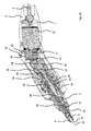
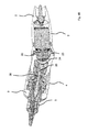
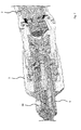
- Fig. 1 shows a schematic representation of a handset 1 for repeated local piercing of a human or animal skin.
- a handle or piece 4 is formed on the outside of a front housing part 3 outside.
- the front housing part 3 removably receives a lancing or needle module 5, which is executable as a disposable module and secured to the front housing part 3, for example by means of a bayonet closure.
- an electric motor is received as a drive in the housing 2, which can be connected via a plug device 6 to a power supply. It can be provided that signal or control connections are also realized via the plug device 6, for example for connecting the handset to an external control device (not shown) via which, for example, a speed control for the electric motor can be provided.
- the housing 2 has a rear housing part 7, which can be designed as a drive module with the electric motor.
- the front and the rear housing part 3, 7 can be releasably connected to each other.
- one or more needles 8 are accommodated in the usual way, which can be extended and retracted by a front housing opening 9 during operation.
- the one or more needles 8 in turn are arranged in the front housing part 3 on a needle holder (not shown) in a conventional manner.
- an insertion opening 10 is arranged, via which a dye can be introduced in a possible operating mode.
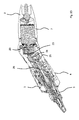
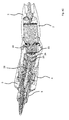
- Fig. 2A to 2D show the handset 1 in section in different working positions.
- the various working positions differ by different rotational positions of a drive-side coupling element 20, which sits on a drive shaft 21 of a drive device 22.
- the drive device 22 is, for example, an electric motor. With the aid of the drive device 22, the drive shaft 21 is set in a rotational movement, so that in this way the drive-side coupling element 20 is rotated.
- the drive-side coupling element 20 is articulated to a proximal connecting rod end 23 of a Stabpleuels 24 in connection. In the illustrated embodiment, the articulated connection is made by means of a ball and socket joint. Due to the rotating movement of the drive-side coupling element 20, the drive-side connecting rod end 23 moves around the drive shaft 21 in a closed path of movement.
- the Fig. 2A to 2D show different rotational positions of the drive-side coupling element 20th
- a distal connecting rod end 25 of the rod 12 is articulated to a driven-side coupling element 26, in the embodiment shown also by means of a ball joint.
- a conversion mechanism is provided with which the rotary drive movement of the drive shaft 21 is converted into an axial forward and backward movement of the output-side coupling element 26 in a guide 27. Due to the rotating movement of the drive-side coupling element 20, a repetitive forward and backward movement of the output-side coupling element 26 is forced via the coupling with the rod connecting rod 24.
- the case executed axial movement of the output-side coupling element 26 has a direction of movement which is not formed parallel to the axial direction of the drive shaft 21, but rather at an angle thereto (inclination) is.
- a needle shaft 30 of a lancing device 31 is received.
- the lancing device 31 has a plurality of needles 8, which in turn are received on the needle shaft 30. In another embodiment, only one needle may be provided. In operation, a piercing needle tip 32 moves back and forth in a front housing opening 9 of the needle module 5, on which a module tip 5a is formed.
- a return device 33 with a diaphragm 34.
- the diaphragm 34 is stretched in the axial direction as the needle shaft 30 is moved forward with the needles 8 received therein, such that the diaphragm 34 provides a restoring force in excess of a biasing force. This acts in addition to a forced by the rod connecting rod 24 return movement.
- a working stroke of the needle shaft 30 is set during forward and backward maximum. This is done by rotating the front and rear housing part 3, 7 relative to each other, which are connected to each other via a hinge connection 35, 36. Due to the rotation, the angle of the inclination between the drive axle and the axis of the forward and backward movement of the needle 8 changes, which changes the distance of the bearings for the drive-side and the driven-side connecting rod ends 23, 25.
- the coupling of front and rear housing part 3, 7 takes place here with the participation of a plastic ring 36.
- a needle projection 37 of the needle tip with respect to the front housing opening 9 is also maximum.
- the needle protrusion 37 can be adjusted.
- a setting member 38 is mounted by means of a screw 39. By means of turning (screws) of the setting component 38, which thereby changes its relative position along the housing axis in the front housing part 3, an adjustment of the needle protrusion 37 takes place.
- An end cap 40 sits on the back of the needle model. 5
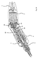
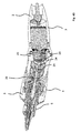
- the Fig. 3A to 3D show the handset 1 comparable to the Fig. 2A to 2D in different working positions, wherein in this embodiment, the stroke of the needle shaft 30 is also set maximum. Unlike the Fig. 2A to 2D but now the needle projection is set to minimum.
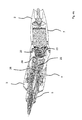
- FIGS. 5A to 5D also show the handset 1 in different working positions, with the stroke of the needle shank 30 now minimized.
- the needle projection is maximized, whereas in the embodiment in the Figs. 5A to 5D the needle projection is minimized again.
- Fig. 6 shows an enlarged perspective view of a portion of the handset 1 with parts of the housing 2, wherein in particular the drive-side coupling element 20 and the coupling thereto drive end connecting rod end 23 and the housing 2 with the housing 2 rotatably coupled by a limited angle, front housing part 3 are hidden by housing ,
- Fig. 7 shows an enlarged sectional view of the handset first
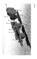
- Fig. 8A shows a schematic perspective view of an arrangement for a hand device for repeated piercing of a skin, in which, in contrast to the embodiments in the Fig. 1 to 7 the axis of the drive shaft 21 and the course of the rectilinear trajectory during forward and backward movement of the piercing device 31 are arranged offset from each other in parallel.
- Fig. 8A shows here an experimental setup in which components of the handset for inspection and test purposes on adapters 80, 81, 82 are arranged. Incidentally, the same reference numerals as used in the foregoing description will be used for the same features.
- the 8B to 8D show the arrangement Fig. 8A in different operating positions for the drive-side coupling element 20 and various settings for a running of the piercing device 31 stroke and a maximum Nadelherausstand.
- Fig. 8B and 8C is set by means of a stroke adjustment of the running of the piercing device 31 stroke maximum.
- Fig. 8B is the distance between the drive side and output side coupling element 20, 26 maximum, in Fig. 8C minimal, the transfer of the in Fig. 8B shown state in the in Fig. 8C shown by a 180 ° rotation of the drive-side coupling element 20 is achieved.
- the executed stroke is set minimal, the distance between the drive side and output side coupling element 20, 26 is also minimal.
- the stroke adjustment is carried out in this design variant by means of a rotating in an eccentric position to the drive longitudinal axis rotatably and slidably mounted member 84, in which in turn, in eccentric position to the central axis of the guide 27 is formed for the output-side coupling element 26. If the component 84 is rotated about its longitudinal axis, the central axis of the output-side coupling element 26 and thus the output-side socket, which receives the output-side rod end 25, the drive longitudinal axis (axial direction of the drive shaft 21) by means of additive or subtractive superimposition of the eccentricities approached or removed.
- the stroke adjustment is effected by means of changing a relative position between the direction of movement of the needle movement of the piercing device 31 on the one hand, in particular the direction of movement of the movement of the driven-side coupling element 26 in the guide 27, from this stroke adjustment in particular a displacement of a rear dead center of the needle movement of the piercing device. and the axial direction of the drive shaft 21. There is a parallel offset. The distance between the two parallel directions (axes) is changed to adjust the stroke.
- a Nadelherausstand is adjustable, so the extent of the supernatant of the piercing needle tip 32 in relation to the front housing opening 9.
- a Nadelherausstand is adjustable, so the extent of the supernatant of the piercing needle tip 32 in relation to the front housing opening 9.
- Fig. 8B and 8C is the Nadelausaus- or needle projection maximum, whereas he in the embodiment in Fig. 8D is minimal.
- the adjustment of the Nadelherausstands done for example by turning an adjusting sleeve 86 in which a module receptacle 87 is mounted by means of a screw 88.
- a rotation angle-dependent axial displacement of all further distally arranged components For this purpose, for example, a grub screw engages in a mounted on the circumference of the adjusting sleeve 86 control curve, which in turn causes a fixed predetermined axial displacement by a defined amount per rotation angle change by its rotation angle slope function.
- the stroke adjustment without the described compensation can be understood as a combined Nadelherausstands-stroke setting, so that can be dispensed with a separate adjustment of Nadelferausstands.
- the rotational movement for stroke adjustment can be decoupled from the angular position of the lancing module.
- a compensation mechanism may be provided which is adapted to compensate for the axial offset between the drive axis and the longitudinal axis of the output-side coupling element 26 so that the lancing module 5 comes to lie in the drive-side axis and the piercing largely in this axis he follows.
- An axis displacement for stroke adjustment can be done instead of by means of a rotary movement by a shift or by their combination or execution in a row.
- the conversion mechanism which in particular comprises the drive-side coupling element 22, the rod connecting rod 24 and the output-side coupling element 26, can be formed completely or partially in the lancing module 5 in the various embodiments of the hand-held device, wherein a releasable torque transmission of the drive device 22 can be provided on the conversion mechanism, so in Fig. 8B between the drive-side coupling element 20 and the drive shaft 21 of the drive device 22nd
- the lancing movement can also take place in the opposite axial direction for all variants of this drive concept, for example, if the front dead center is to be influenced by the combined stroke needle out stand adjustment or the space required, for example, if a compact short lancing device is desired instead of an elongated pin-shaped.
Abstract
Handgerät zum wiederholten lokalen Aufstechen einer menschlichen oder einer tierischen Haut, mit einem Gehäuse (2), einer Antriebseinrichtung (22) mit der über eine Antriebswelle (21) eine rotierende Bewegung um eine Drehachse bereitgestellt wird, einem an die Antriebswelle (21) koppelnden Wandlungsmechanismus (20, 24, 26), der in dem Gehäuse (2) angeordnet ist, die rotierende Bewegung in eine Antriebsbewegung entlang einer Antriebsbewegungsrichtung zu wandeln, und einer Stecheinrichtung (31), die eine Stechnadel (8) aufweist, welche an einem Nadelschaft (30) angeordnet ist, der zusammen mit der Stechnadel (8) entlang einer Bewegungsbahn wiederholt vor und zurück bewegbar ist und mit dem Wandlungsmechanismus (20, 24, 26) in Verbindung steht, wobei der Wandlungsmechanismus (20, 24, 26) eine Stabkurbeleinrichtung aufweist und ein von der Stechnadel (8) beim Vor- und Zurückbewegen ausgeführter Hub einstellbar ist, indem eine Relativlage zwischen einer Axialrichtung der Drehachse und der Antriebsbewegungsrichtung verändert wird.A hand-held device for repeated local piercing of a human or an animal skin, comprising a housing (2), a drive device (22) with which a drive shaft (21) provides a rotational movement about an axis of rotation, a conversion mechanism coupling to the drive shaft (21) (20, 24, 26) disposed in the housing (2) for converting the rotary motion into drive motion along a drive motion direction, and piercing means (31) having a piercing needle (8) attached to a needle shank (8); 30) which is reciprocally movable back and forth along a movement path together with the piercing needle (8) and communicates with the conversion mechanism (20, 24, 26), the conversion mechanism (20, 24, 26) having a rod cranking means and an executed by the piercing needle (8) during the forward and backward stroke is adjustable by a relative position between an axial direction of the rotation axis un d the drive movement direction is changed.
Description
Die Erfindung betrifft ein Handgerät zum wiederholten Aufstechen einer menschlichen oder einer tierischen Haut.The invention relates to a hand-held device for repeatedly piercing a human or an animal skin.
Vorrichtungen zum lokalen Aufstechen einer menschlichen oder einer tierischen Haut werden in der Regel als Handgeräte ausgeführt. Vom Bedienpersonal können derartige Handgeräte zum Aufbringen einer Farbe für eine Tätowierung (Tattoo) und / oder permanentes Make-up im Bereich der Hautoberfläche verwendet werden. Aber auch das Einbringen kosmetischer oder medizinischer Wirkstoffe über die Haut ist mit solchen Geräten möglich, indem die Haut lokal aufgestochen wird. Darüber hinaus können solche Geräte verwendet werden, ohne dass irgendeine Substanz eingebracht wird, zum Beispiel zur Hautstimulierung.Devices for local piercing of a human or an animal skin are usually carried out as handsets. Operators may use such hand-held devices to apply a tattoo paint and / or permanent make-up around the skin surface. But also the introduction of cosmetic or medical agents through the skin is possible with such devices by the skin is locally pierced. In addition, such devices can be used without introducing any substance, for example for skin stimulation.
Ein Handgerät zum lokalen Aufstechen einer Haut ist beispielsweise aus der Druckschrift
Aus dem Dokument
Aufgabe der Erfindung ist es, ein Handgerät zum wiederholten lokalen Aufstechen einer menschlichen oder einer tierischen Haut anzugeben, bei denen im Betrieb des Handgerätes der Bedienkomfort verbessert ist, insbesondere hinsichtlich störender Begleiterscheinungen wie zum Beispiel Geräusche oder Vibrationen des Handgerätes.The object of the invention is to provide a hand-held device for repeated local piercing of a human or an animal skin in which the ease of use is improved during operation of the handset, in particular with regard to disturbing side effects such as noise or vibration of the handset.
Zur Lösung der Aufgabe ist ein Handgerät zum wiederholten lokalen Aufstechen einer menschlichen oder tierischen Haut nach dem unabhängigen Anspruch 1 geschaffen. Vorteilhafte Ausgestaltungen sind Gegenstand von abhängigen Unteransprüchen.To solve the problem, a hand-held device for repeated local piercing of a human or animal skin is provided according to
Es ist ein Handgerät zum wiederholten lokalen Aufstechen einer menschlichen oder tierischen Haut geschaffen, welches ein Gehäuse mit einem hieran gebildeten Handgriff aufweist. Im Betrieb des Handgerätes, welches im Fall der Nutzung zum Ausbilden von Tattoos oder permanentem Makeup auch als Tätowiervorrichtung bezeichnet werden kann, greift der Nutzer den Handgriff, um das Handgerät dann zu führen. Andere Anwendungen sehen das lokale Aufstechen der Haut zum Einbringen eines kosmetischen oder medizinischen Wirkstoffes vor. Auch eine Injektion von Wirkstoffen durch Kanülen kann erfolgen. Aber auch für das lokale Aufstechen der menschlichen oder tierischen Haut ohne Einbringen irgendeiner Substanz kann das Handgerät genutzt werden, zum Beispiel zur Hautstimulierung. Im Gehäuse ist eine Antriebseinrichtung aufgenommen, mit der über eine Antriebswelle eine rotierende Antriebskraft bereitgestellt wird. Hierfür kann ein Elektromotor vorgesehen sein.It is a hand tool for repeated local piercing a human or animal skin created, which has a housing with a handle formed thereon. In the operation of the handset, which in the case of use for forming tattoos or permanent Makeup can also be referred to as a tattoo machine, the user grasps the handle to then guide the handset. Other applications include local piercing of the skin for the introduction of a cosmetic or medicinal agent. An injection of active ingredients through cannulas can also take place. But even for the local piercing of human or animal skin without introducing any substance, the handset can be used, for example for skin stimulation. In the housing, a drive device is received, with which via a drive shaft, a rotating drive force is provided. For this purpose, an electric motor can be provided.
An die Antriebswelle koppelt ein Wandlungsmechanismus, der im Gehäuse angeordnet und eingerichtet ist, die rotierende Bewegung (rotierende Antriebskraft) um eine Drehachse in eine Antriebsbewegung entlang einer Antriebsbewegungsrichtung zu wandeln. Die hierdurch bereitgestellte Antriebskraft ist in einem Ausführungsbeispiel eine axial ausgerichtete Antriebsbewegung.To the drive shaft, a conversion mechanism disposed in the housing and configured to convert the rotary motion (rotary drive force) about a rotation axis into drive motion along a drive movement direction. The driving force provided thereby is in one embodiment an axially aligned drive movement.
Es ist weiterhin eine Stecheinrichtung vorgesehen, die im Gehäuse aufgenommen ist und eine oder mehrere Stechnadeln aufweist, die an einer Nadelaufnahme angeordnet sind. Im Fall von mehreren Stechnadeln können diese in Gruppen angeordnet sein, in denen die Nadeln einander nahestehen. Aber auch die Verteilung von Nadeln oder Nadelgruppen über die Fläche einer Nadelplatte kann vorgesehen sein. In diesem Fall ist die Nadelaufnahme mit einer Nadelplatte gebildet. Die Nadelaufnahme ist verbunden mit dem Wandlungsmechanismus und wird zusammen mit der einen oder den mehreren Stechnadeln im Betrieb entlang einer Bewegungsbahn wiederholt vor und zurück bewegt, beispielsweise einer geradlinigen Bewegungsbahn, zum Beispiel in einer axialer Richtung.There is further provided a lancing device, which is accommodated in the housing and has one or more piercing needles, which are arranged on a needle holder. In the case of multiple piercing needles, these may be arranged in groups in which the needles are close to each other. But also the distribution of needles or groups of needles over the surface of a needle plate can be provided. In this case, the needle holder is formed with a needle plate. The needle receptacle is connected to the conversion mechanism and, together with the one or more piercing needles, is repeatedly moved back and forth along a path of movement, for example a rectilinear trajectory, for example in an axial direction.
Der Wandlungsmechanismus weist eine Stabkurbeleinrichtung auf, die an die Antriebswelle koppelt. Auf diese Weise kann ein Stabkurbeltrieb realisiert werden. Ein von der Stechnadel beim Vor- und Zurückbewegen ausgeführter Hub ist einstellbar, indem eine Relativlage zwischen einer Axialrichtung der Drehachse und der Antriebsbewegungsrichtung verändert wird.The conversion mechanism has a bar cranking device which couples to the drive shaft. In this way, a bar crank drive can be realized. A stroke performed by the piercing needle when moving back and forth is adjustable by changing a relative position between an axial direction of the rotational axis and the driving direction of movement.
Das Einstellen des Hubs kann manuell oder mittels eines Einstellantriebs erfolgen.The adjustment of the stroke can be done manually or by means of an adjustment drive.
Bei dem Handgerät kann die Antriebseinrichtung, insbesondere ein Elektromotor, in einem zum Handgriff am Gehäuse querstehenden Gehäuseabschnitt aufgenommen sein. Die Antriebseinrichtung kann eingerichtet sein, im Betrieb eine drehende Antriebsbewegung von wenigstens etwa 1.800 min-1 (30 Hz) bereitzustellen.In the hand-held device, the drive device, in particular an electric motor, can be accommodated in a housing section which is transverse to the handle on the housing. The drive means may be arranged to provide a rotational driving movement of at least about 1,800 min -1 (30 Hz) during operation.
Bei einer beispielhaften Ausführung der Stabkurbeleinrichtung kann in einer Ausführung ein antriebsseitiges Kopplungselement vorgesehen sein, welches an die Antriebswelle koppelt und im Betrieb der rotierenden Antriebsbewegung der-Antriebswelle entsprechend rotiert. Das antriebsseitige Kopplungselement kann in einer Ausgestaltung als Antriebsscheibe ausgeführt sein. An das antriebsseitige Kopplungselement kann ein proximales Pleuelende eines Stabpleuels der Stabkurbeleinrichtung gelenkig koppeln, derart, dass das proximale Pleuelende beim Rotieren des antriebsseitigen Kopplungselementes auf einer geschlossenen Bewegungsbahn, insbesondere Kreisbahn, um die Rotationsachse der Antriebswelle herumbewegt wird. Das antriebsseitige Kopplungselement kann direkt auf der Antriebswelle sitzen, so dass es bei deren Rotation mitbewegt wird. Hierbei läuft dann das proximale Pleuelende auf seiner geschlossenen Bewegungsbahn um die Richtung der Rotationsachse der Antriebswelle herum. Ein distales Pleuelende des Stabpleuels kann an ein abtriebseitiges Kopplungselement gelenkig koppeln, welches zum Übertragen der axial ausgerichteten Antriebsbewegung dann an den Nadelschaft koppelt, so dass im Betrieb der Nadelschaft der axial ausgerichteten Antriebsbewegung vor- und zurückbewegt wird.In an exemplary embodiment of the rod crank mechanism, in one embodiment, a drive-side coupling element may be provided, which couples to the drive shaft and correspondingly rotates during operation of the rotating drive movement of the drive shaft. The drive-side coupling element can be designed in one embodiment as a drive pulley. A proximal connecting rod end of a rod of the rod crank mechanism can articulate on the drive-side coupling element, such that the proximal connecting rod end is moved around the axis of rotation of the drive shaft when the drive-side coupling element rotates on a closed path of movement, in particular a circular path. The drive-side coupling element can sit directly on the drive shaft, so that it is moved along with its rotation. In this case, the proximal connecting rod end then runs on its closed trajectory around the direction of the axis of rotation of the drive shaft. A distal connecting rod end of the rod can pivotally couple to a driven-side coupling element which then couples to the needle shaft for transmitting the axially aligned drive motion such that during operation of the needle shaft the axially directed drive motion is moved back and forth.
Die Gelenkverbindung zwischen dem proximalen Pleuelende und dem antriebseitigen Kopplungselement und / oder die Gelenkverbindung zwischen dem distalen Pleuelende und dem abtriebseitigen Kopplungselement kann eingerichtet sein, eine räumliche Schwenkbarkeit des jeweiligen Pleuelendes gegenüber dem Kopplungselement zulassend ausgeführt sein.The articulated connection between the proximal connecting rod end and the drive-side coupling element and / or the articulated connection between the distal end of the connecting rod and the output-side coupling element can be designed to permit spatial pivoting of the respective connecting rod end relative to the coupling element.
Das Gehäuse kann aus einem einzigen Material oder einer Kombination verschiedener Materialien bestehen, wozu insbesondere Metall und Kunststoff gehören. Gehäuseabschnitte können lösbar montiert sein, um zum Beispiel Bereiche des Gehäuseinneren zu Austausch- oder Wartungszwecken freizugeben. Aus dem Gehäuse kann eine Kabelverbindung herausgeführt sein, die zum Anschluss des Handgerätes an ein externes Steuergerät dient. Die Kabelverbindung kann dem Anschließen eines Elektromotors an eine Energiequelle dienen, insbesondere über das Steuergerät. Die Kabelverbindung kann Datenkabel aufweisen, über die zwischen dem Handgerät und dem Steuergerät elektronische Daten austauschbar sind. Ein solcher Datenaustausch zwischen Handgerät und Steuergerät kann alternativ oder ergänzend auch über eine drahtlose Datenverbindung ausgeführt werden, zum Beispiel unter Verwendung der Bluetooth-Technologie. Steuergeräte für Handgeräte zum wiederholten lokalen Aufstechen einer menschlichen oder tierischen Haut sind als solche in verschiedenen Ausführungsformen bekannt und werden hier daher nicht näher erläutert.The housing may consist of a single material or a combination of different materials, including in particular metal and plastic. Housing sections may be detachably mounted to, for example, release areas of the housing interior for replacement or maintenance. From the housing, a cable connection can be led out, which serves to connect the handset to an external control unit. The cable connection can serve to connect an electric motor to a power source, in particular via the control unit. The cable connection may include data cables through which electronic data is interchangeable between the handset and the controller. Such data exchange between the hand-held device and the control device can alternatively or additionally also be carried out via a wireless data connection, for example using the Bluetooth technology. Control devices for handheld devices for repeated local piercing of a human or animal skin are known as such in various embodiments and are therefore not explained here.
In den verschiedenen Ausführungsformen kann die Kopplung zwischen Wandlungsmechanismus und Nadelaufnahme, die mit einem Nadelschaft gebildet sein kann, derart ausgeführt sein, dass im Betrieb die Nadelaufnahme aufgrund der bereitgestellten Antriebskraft nicht nur vorgefahren wird, sondern auch mittels des das Kopplungsbauteil umfassenden Wandlungsmechanismus zurückgezogen wird. Bei dieser Ausführungsform stellt der Wandlungsmechanismus selbst eine Rückstellkraft bereit. Alternativ oder ergänzend kann vorgesehen sein, dass die Rückstellkraft wenigstens teilweise von einem elastischen Element bereitgestellt wird, beispielsweise einer Feder oder einer Membran. Bei dieser Ausführung erfolgt das Aus- oder Vorfahren der Nadelaufnahme mit der einen oder den mehreren Stechnadeln gegen eine elastische Vorspannung, die ihrerseits dann zum Zurückbewegen beiträgt oder dieses allein bewirkt. Das elastische Element zieht sich nach dem Strecken beim Ausfahren der Stechnadeln selbsttätig wieder zusammen und bewirkt so die Rückbewegung der einen oder der mehreren Nadeln.In the various embodiments, the coupling between the conversion mechanism and the needle receptacle, which may be formed with a needle shaft, be designed such that in operation, the needle holder is not only driven forward due to the provided driving force, but is also retracted by means of the coupling member comprehensive conversion mechanism. In this embodiment, the conversion mechanism itself provides a restoring force. Alternatively or additionally, it may be provided that the restoring force is at least partially provided by an elastic element, for example a spring or a membrane. In this embodiment, the training or ancestors of the needle holder with the one or more piercing needles is against a resilient bias, which in turn then contributes to moving back or this alone causes. The elastic element automatically contracts again after stretching during extension of the piercing needles and thus effects the return movement of the one or more needles.
Der Wandlungsmechanismus kann eine Drehentkopplung aufweisen. Die Drehentkopplung sorgt dafür, dass ausgehend von der rotierenden Bewegung des antriebseitigen Kopplungselementes kein Drehmoment auf den Nadelschaft mit der einen oder mehreren hierin aufgenommenen Nadeln übertragen wird. Das Entkoppeln von der drehenden Antriebsbewegung kann in einer mechanischen Kette des Wandlungsmechanismus an einem oder mehreren Übergängen zwischen benachbarten Elementen der Übertragungskette vorgesehen sein.The conversion mechanism may have a rotary decoupling. The rotational decoupling ensures that, based on the rotational movement of the drive-side coupling element, no torque is transmitted to the needle shaft with the one or more needles received therein. The uncoupling of the rotary drive movement may be provided in a mechanical chain of the conversion mechanism at one or more transitions between adjacent elements of the transmission chain.
Die gelenkige Kopplung zwischen dem proximalen Pleuelende und dem antriebseitigen Kopplungselement kann drehentkoppelnd ausgeführt sein. Die Drehentkopplung kann mit Hilfe eines Kugelkopfgelenkes ausgeführt sein, bei dem ein Kugelkopf in einer Kugelpfanne drehbar aufgenommen ist. In Verbindung mit dem proximalen Pleuelende geht es hierbei insbesondere um eine Drehung um die Längsachse des Stabpleuels. Der Kugelkopf kann an dem proximalen Pleuelende oder am antriebseitigen Kopplungselement vorgesehen sein. Anstelle der Aufnahme eines Kugelkopfes in der Kugelpfanne kann der Kugelkopf mit einer hierauf sitzenden Kugelschale versehen sein, welche ihrerseits in der Kugelpfanne drehbar aufgenommen ist, wohingegen die Kugelschale fest auf dem Kugelkopf gespannt ist.The articulated coupling between the proximal connecting rod end and the drive-side coupling element may be rotationally coupling. The rotary decoupling can be carried out by means of a ball joint, in which a ball head in a ball socket is received rotatably. In connection with the proximal end of the connecting rod, this is in particular a rotation about the longitudinal axis of the rod. The ball head may be provided on the proximal connecting rod end or on the drive-side coupling element. Instead of receiving a ball head in the ball socket, the ball head may be provided with a ball socket seated thereon, which in turn is rotatably received in the ball socket, whereas the ball socket is tight on the ball head.
Eine Ausführungsform sieht vor, dass die gelenkige Kopplung zwischen dem distalen Pleuelende und dem abtriebseitigen Kopplungselement drehentkoppelnd ausgeführt ist. Es gelten die obigen Ausführungen in Verbindung mit der gelenkigen Aufnahme des proximalen Pleuelendes entsprechend.One embodiment provides that the articulated coupling between the distal end of the connecting rod and the output-side coupling element is designed to be rotationally coupling. The above statements apply in conjunction with the articulated receiving the proximal connecting rod end accordingly.
Bevorzugt sieht eine Fortbildung vor, dass das proximale Pleuelende und das distale Pleuelende am Stabpleuel drehentkoppelt aufgenommen sind. Bei dieser Ausführungsform kann sich eines der Pleuelenden unabhängig von dem anderen Pleuelende um die Längsachse des Stabpleuels drehen. In einer Ausführungsform sind proximales und distales Pleuelende mit einem sich zur Mitte des Stabpleuels hin erstreckenden Abschnitt drehbar in einer Pleuelhülse aufgenommen.Preferably, a further training provides that the proximal end of the connecting rod and the distal end of the connecting rod are received in torsion coupling on the rod connecting rod. In this embodiment, one of the connecting rod ends can rotate independently of the other connecting rod end about the longitudinal axis of the Stabpleuels. In one embodiment, proximal and distal connecting rod ends are rotatably received in a connecting rod sleeve with a portion extending toward the center of the rod.
Eine Ausgestaltung kann vorsehen, dass das proximale Pleuelende mit dem antriebseitigen Kopplungselement und / oder das distale Pleuelende mit dem abtriebseitigen Kopplungselement mittels eines Kugelgelenkes gelenkig gekoppelt sind.An embodiment may provide that the proximal connecting rod end are pivotally coupled to the drive-side coupling element and / or the distal connecting rod end is articulated to the output-side coupling element by means of a ball joint.
Eine Weiterbildung kann vorsehen, dass das abtriebseitige Kopplungselement über eine starre Verbindung mit dem Nadelschaft verbunden oder einstückig hiermit ausgeführt ist. Das abtriebseitige Kopplungselement kann mit dem Nadelschaft in einer gemeinsamen Führung im Gehäuse angeordnet sein. Alternativ können für abtriebseitiges Kopplungselement und Nadelschaft voneinander getrennte Führungen im Gehäuse vorgesehen sein. Die eine oder die mehreren Führungen können parallel oder schräg zur Rotationsachse der Antriebswelle gebildet sein. Im Fall einer einstückigen Ausführung kann die gelenkige Ankopplung des distalen Pleuelendes auf einer der Antriebseinrichtung zugewandten Stirnseite des Nadelschaftes angeordnet sein. Die Verbindung zwischen abtriebseitigen Kopplungselement und Nadelschaft kann lösbar oder nicht lösbar ausgeführt sein. Es kann eine mechanische und / oder magnetische Kopplung zum Verbindung genutzt werden.A development may provide that the output-side coupling element is connected via a rigid connection with the needle shaft or integral with it. The output-side coupling element can be arranged with the needle shaft in a common guide in the housing. Alternatively, mutually separate guides can be provided in the housing for output-side coupling element and needle shaft. The one or more guides may be formed parallel or obliquely to the axis of rotation of the drive shaft. In the case of a one-piece embodiment, the articulated coupling of the distal end of the connecting rod can be arranged on an end face of the needle shaft facing the drive device. The connection between the output side coupling element and the needle shaft can be made detachable or non-detachable. It can be used a mechanical and / or magnetic coupling to the connection.
Eine Weiterbildung sieht vor, dass an den Nadelschaft eine Rückholeinrichtung koppelt. Die Rückholeinrichtung kann zum Beispiel ein Federelement aufweisen. Mit Hilfe der Rückholeinrichtung kann eine Rückstellkraft für den Nadelschaft und / oder das abtriebseitige Kopplungselement bereitgestellt sein.A further embodiment provides that a return device is coupled to the needle shaft. The return device may for example comprise a spring element. With the aid of the return device, a restoring force for the needle shaft and / or the output-side coupling element can be provided.
Die Antriebsachse (Antriebsseite) kann nicht parallel zur Richtung der Bewegung (Abtriebsseite) angeordnet sein, zum Beispiel einer axial ausgerichteten Bewegung. Hierdurch ist eine Schrägstellung der beiden Achsen zueinander ausgebildet. Der Winkel zwischen Richtung der Antriebsachse (axiale Richtung der Antriebswelle) und Richtung der Bewegung, welcher von Null Grad verschieden ist, kann einstellbar sein. Mittels Verstellen des Winkels (Änderung der Schrägstellung) kann die Hubeinstellung ausführbar sein. Zum Verstellen des Winkels kann in einem Ausführungsbeispiel vorgesehen sein, gelenking miteinander verbundene Gehäuseteile relativ zueinander zu verlagern, sei es manuell oder mittels eines Antriebs. In einer Ausführung ist der Winkel zwischen Richtung der Antriebsachse und Richtung der Bewegung verschieden von 90 Grad.The drive shaft (drive side) can not be arranged parallel to the direction of movement (output side), for example, an axially aligned movement. As a result, an inclination of the two axes is formed to each other. The angle between the direction of the drive shaft (axial direction of the drive shaft) and the direction of the movement, which is different from zero degrees, may be adjustable. By adjusting the angle (change of inclination), the stroke adjustment can be executed. To adjust the angle can be provided in one embodiment, articulated interconnected housing parts to relocate relative to each other, be it manually or by means of a drive. In one embodiment, the angle between the direction of the drive axis and the direction of movement is different than 90 degrees.
Eine geradlinige Bewegungsbahn beim Vor- und Zurückfahren des Nadelschaftes und die Antriebsachse können parallel versetzt zueinander angeordnet sein. Eine Hubeinstellung ist hierbei zum Beispiel mittels Verändern des Parallelversatzes ausführbar, also einer Relativverlagerung zur Abstandsänderung der parallel verlaufenden Richtungen / Achsen. Hierzu kann zum Beispiel ein das abtriebsseitige Pleuelende aufnehmendes abtriebsseitiges Koppelelement in einem zumindest drehbar gelagerten Bauteil in exzentrischer Lage aufgenommen sein, so dass mittels Drehen die exzentrische Lage veränderbar ist, was den Parallelversatz ändert.A linear trajectory when driving back and forth of the needle shaft and the drive shaft can be arranged offset from each other in parallel. A stroke adjustment is in this case, for example by means of changing the parallel offset executable, so a relative displacement for changing the distance of the parallel directions / axes. For this purpose, for example, the output side connecting rod end receiving output side coupling element can be accommodated in an at least rotatably mounted component in an eccentric position, so that by means of rotation, the eccentric position is changed, which changes the parallel offset.
Eine Ausgestaltung sieht vor, dass ein maximaler Nadelüberstand einer Stechnadelspitze der Stechnadel in Bezug auf eine vordere Gehäuseöffnung einstellbar ist.One embodiment provides that a maximum needle projection of a piercing needle tip of the piercing needle is adjustable with respect to a front housing opening.
Das Gehäuse kann mit mehreren Gehäusemodulen gebildet sein, wobei in einem Antriebsmodul die Antriebseinrichtung und in einem Stechmodul die Stecheinrichtung angeordnet ist. Die Gehäusemodule können lösbar miteinander verbunden sein. In einer Ausgestaltung von lösbar miteinander verbundenen Gehäusemodulen kann das Stechmodul, welches auch als Nadelmodul bezeichnet werden kann, als sterilisiertes Einwegmodul ausgeführt sein. Auch ein Gehäuseteil oder -modul mit einem Handgriff kann als lösbares Modul gebildet sein. Das Gehäuseteil kann neben dem Stech- oder Nadelmodul, welches an dem Gehäuseteil lösbar angeordnet sein kann, als weiteres Einwegmodul oder als wiederverwendbares Modul ausgeführt sein. Es ist weiterhin denkbar, Stechmodul und Gehäuseteil mit Handgriff als eine Einheit auszubilden, zum Beispiel auch einstückig.The housing may be formed with a plurality of housing modules, wherein in a drive module, the drive means and in a piercing module, the piercing device is arranged. The housing modules can be releasably connected to each other. In an embodiment of detachably interconnected housing modules, the lancing module, which may also be referred to as a needle module, be designed as a sterilized disposable module. Also, a housing part or module with a handle can be formed as a detachable module. The housing part can be designed as a further disposable module or as a reusable module in addition to the piercing or needle module, which can be detachably arranged on the housing part. It is also conceivable to form lancing module and housing part with handle as a unit, for example, in one piece.
Im Folgenden werden weitere Ausführungsbeispiele unter Bezugnahme auf Figuren einer Zeichnung näher erläutert. Hierbei zeigen:
- Fig. 1
- eine schematische Darstellung eines Handgeräts zum wiederholten lokalen Aufstechen einer menschlichen oder tierischen Haut von der Seite,
- Fig. 2A bis 2D
- eine schematische Darstellung des Handgeräts im Schnitt in verschiedenen Arbeitsstellungen, wobei ein Arbeitshub und ein Nadelüberstand maximal eingestellt sind,
- Fig. 3A bis 3D
- schematische Darstellungen eines Handgeräts in verschiedenen Arbeitsstellungen im Schnitt, wobei der Arbeitshub maximal und der Nadelüberstand minimal eingestellt sind,
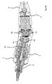
- Fig. 4A bis 4D
- schematische Darstellungen eines Arbeitsgeräts in verschiedenen Arbeitsstellungen im Schnitt, wobei der Arbeitshub minimal und der Nadelüberstand maximal eingestellt sind,
- Fig. 5A bis 5D
- schematische Darstellungen eines Arbeitsgerätes in verschiedenen Arbeitsstellungen im Schnitt, wobei der Arbeitshub und der Nadelüberstand minimal eingestellt sind,
- Fig. 6
- eine vergrößerte perspektivische Darstellung eines Kopplungsbereiches,
- Fig. 7
- eine vergrößerte Schnittdarstellung eines Teils des Handgeräts,
- Fig. 8A bis 8D
- schematische Darstellungen einer Anordnung von Komponenten für ein Handgerät in verschiedenen Arbeitsstellungen, wobei eine geradlinige Bewegungsbahn beim Vor- und Zurückfahren des Nadelschaftes und die Antriebsachse parallel versetzt zueinander angeordnet sind.
- Fig. 1
- a schematic representation of a hand-held device for repeated local piercing of a human or animal skin from the side,
- Fig. 2A to 2D
- a schematic representation of the handset in section in different working positions, with a working stroke and a needle projection are set to the maximum,
- Fig. 3A to 3D
- schematic representations of a hand-held device in different working positions in section, wherein the maximum working stroke and the needle projection are set to a minimum,
- Figs. 4A to 4D
- schematic representations of a working device in different working positions in the section, wherein the working stroke is minimized and the needle protrusion maximum,
- Figs. 5A to 5D
- schematic representations of a working device in different working positions in section, wherein the working stroke and the needle projection are set to a minimum,
- Fig. 6
- an enlarged perspective view of a coupling region,
- Fig. 7
- an enlarged sectional view of a part of the handset,
- 8A to 8D
- schematic representations of an arrangement of components for a handset in different working positions, wherein a rectilinear trajectory during forward and backward movement of the needle shaft and the drive shaft are arranged offset from each other in parallel.
Bei der dargestellten Ausführungsform ist in dem Gehäuse 2 ein Elektromotor als Antrieb aufgenommen, welcher über eine Steckereinrichtung 6 an eine Energieversorgung angeschlossen werden kann. Es kann vorgesehen sein, dass über die Steckereinrichtung 6 auch Signal- oder Steueranschlüsse realisiert werden, zum Beispiel zum Verbinden des Handgerätes mit einer externen Steuereinrichtung (nicht dargestellt), über die zum Beispiel eine Drehzahlregelung für den Elektromotor bereitgestellt sein kann.In the illustrated embodiment, an electric motor is received as a drive in the
Das Gehäuse 2 weist ein hinteres Gehäuseteil 7 auf, welches als ein Antriebsmodul mit dem Elektromotor ausgeführt sein kann. Das vordere und das hintere Gehäuseteil 3, 7 können lösbar miteinander verbunden sein.The
Im Stech- oder Nadelmodul 5 sind in üblicher Weise ein oder mehrere Nadeln 8 aufgenommen, die im Betrieb durch eine vordere Gehäuseöffnung 9 aus- und eingefahren werden können. Die eine oder die mehreren Nadeln 8 ihrerseits sind im vorderen Gehäuseteil 3 an einer Nadelaufnahme (nicht dargestellt) in üblicher Weise angeordnet.In the piercing or
Am Stech- oder Nadelmodul 5 ist eine Einführöffnung 10 angeordnet, über welche in einer möglichen Betriebsart ein Farbstoff einführbar ist.At the piercing or
Ein distales Pleuelende 25 des Stabpleuels 24 ist an einem abtriebsseitigen Kopplungselement 26 gelenkig gelagert, im gezeigten Ausführungsbeispiel ebenfalls mithilfe eines Kugelgelenkes. Mithilfe des antriebsseitigen Kopplungselementes 20, des abtriebsseitigen Kopplungselementes 26 sowie des Stabpleuels 24 ist ein Wandlungsmechanismus bereitgestellt, mit dem die rotierende Antriebsbewegung der Antriebswelle 21 in eine axiale Vor- und Zurückbewegung des abtriebsseitigen Kopplungselementes 26 in einer Führung 27 umgewandelt wird. Aufgrund der rotierenden Bewegung des antriebsseitigen Kopplungselementes 20 wird über die Kopplung mit dem Stabpleuel 24 eine repetierende Vorwärts- und Rückwärtsbewegung des abtriebsseitigen Kopplungselementes 26 erzwungen. Die hierbei ausgeführte axiale Bewegung des abtriebsseitigen Kopplungselementes 26 weist eine Bewegungsrichtung auf, die mit der axialen Richtung der Antriebswelle 21 nicht parallel gebildet ist, sondern vielmehr in einem Winkel hierzu (Schrägstellung) steht.A distal connecting
An das abtriebsseitige Kopplungselement 26 koppelt ein Zwischenstück 28, an dessen Vorderseite in einer Aufnahme 29 ein Nadelschaft 30 einer Stecheinrichtung 31 aufgenommen ist. Die Stecheinrichtung 31 weist mehreren Nadeln 8 auf, die ihrerseits an dem Nadelschaft 30 aufgenommen sind. In einer anderen Ausführung kann auch nur eine Nadel vorgesehen sein. Im Betrieb bewegt sich eine Stechnadelspitze 32 vor und zurück in einer vorderen Gehäuseöffnung 9 des Nadelmoduls 5, an welchem eine Modulspitze 5a gebildet ist.To the output
Es ist eine Rückstelleinrichtung 33 mit einer Membran 34 vorgesehen. Die Membran 34 wird in axialer Richtung gestreckt, wenn der Nadelschaft 30 mit den hierin aufgenommenen Nadeln 8 nach vorne bewegt wird, derart, dass die Membran 34 eine über eine Vorspannkraft hinausgehende Rückstellkraft bereitstellt. Diese wirkt ergänzend zu einer durch den Stabpleuel 24 erzwungenen Rückbewegung.There is provided a return device 33 with a
Bei der in den
Ein Nadelüberstand 37 der Nadelspitze in Bezug zu der vorderen Gehäuseöffnung 9 ist ebenfalls maximal. Der Nadelüberstand 37 kann eingestellt werden. Hierzu ist ein Einstellbauteil 38 mittels einer Schraubverbindung 39 gelagert. Mittels Drehen (Schrauben) des Einstellbauteils 38, welches hierdurch seine Relativlage längs der Gehäuseachse im vorderen Gehäuseteil 3 ändert, erfolgt eine Einstellung des Nadelüberstandes 37.A
Eine Abschlusskappe 40 sitzt rückseitig an dem Nadelmodel 5.An end cap 40 sits on the back of the needle model. 5
Die
Die
Die
Bei der Ausgestaltung in den
Bei der Darstellung in
Weiterhin ist ein Nadelherausstand einstellbar, also der Umfang des Überstandes der Stechnadelspitze 32 in Relation zur vorderen Gehäuseöffnung 9. Bei der Ausgestaltung in
Um einen Nadelherausstand bei der Hubeinstellung festzuhalten (konstant zu halten), erfolgt bei der gezeigten Ausführung mit der Drehung des Bauteils 84 zur Hubeinstellung dank einer Steuerkurve eine drehwinkelabhängige axiale Verlagerung aller weiter distal angeordneten Bauteile. Dazu greift beispielsweise ein Gewindestift in eine auf dem Umfang der Einstellhülse 86 angebrachte Steuerkurve, die wiederum durch ihre Drehwinkel-Steigungs-Funktion eine fest vorgegebene axiale Verschiebung um einen definierten Betrag je Drehwinkeländerung bewirkt. Die Hubeinstellung ohne die beschriebene Kompensation kann als kombinierte Nadelherausstands-Hub-Einstellung aufgefasst werden, so dass auf eine separate Einstellung des Nadelherausstands verzichtet werden kann.In order to hold a Nadelherausstand in the stroke adjustment (to keep constant), takes place in the embodiment shown with the rotation of the
Die Drehbewegung zur Hubeinstellung kann von der Winkelstellung des Stechmoduls entkoppelt sein.The rotational movement for stroke adjustment can be decoupled from the angular position of the lancing module.
Bei einer auf
Eine Achsenverlagerung zur Hubeinstellung kann statt vermittels einer Drehbewegung auch durch eine Verschiebung oder durch deren Kombination oder Ausführung hintereinander erfolgen.An axis displacement for stroke adjustment can be done instead of by means of a rotary movement by a shift or by their combination or execution in a row.
Der Wandlungsmechanismus, welcher insbesondere das antriebsseitige Kopplungselement 22, das Stabpleuel 24 sowie das abtriebsseitige Kopplungselement 26 umfasst, kann bei den verschiedenen Ausgestaltungen des Handgerätes ganz oder teilwiese im Stechmodul 5 ausgebildet sein, wobei eine lösbare Drehmomentübertragung der Antriebseinrichtung 22 auf den Wandlungsmechanismus vorgesehen sein kann, also in
Die Stechbewegung kann für alle Varianten dieses Antriebskonzepts auch in die entgegengesetzte Achsenrichtung erfolgen, beispielsweise wenn der vordere Totpunkt durch die kombinierte Hub-Nadelherausstand-Einstellung beeinflusst werden soll oder es der Bauraum erforderlich macht, beispielsweise, wenn ein kompaktes kurzes Stechgerät gewünscht wird statt eines langgestreckten stiftförmigen.The lancing movement can also take place in the opposite axial direction for all variants of this drive concept, for example, if the front dead center is to be influenced by the combined stroke needle out stand adjustment or the space required, for example, if a compact short lancing device is desired instead of an elongated pin-shaped.
Die in der vorstehenden Beschreibung, den Ansprüchen sowie der Zeichnung offenbarten Merkmale können sowohl einzeln als auch in beliebiger Kombination für die Verwirklichung der verschiedenen Ausführungen von Bedeutung sein.The features disclosed in the above description, the claims and the drawings may be important both individually and in any combination for the realization of the various embodiments.
Claims (12)
Priority Applications (2)
| Application Number | Priority Date | Filing Date | Title |
|---|---|---|---|
| EP15171689.1A EP2954926B1 (en) | 2014-06-12 | 2015-06-11 | Handheld device for the repeated puncturing of human or animal skin |
| PL15171689T PL2954926T3 (en) | 2014-06-12 | 2015-06-11 | Handheld device for the repeated puncturing of human or animal skin |
Applications Claiming Priority (2)
| Application Number | Priority Date | Filing Date | Title |
|---|---|---|---|
| EP14172103 | 2014-06-12 | ||
| EP15171689.1A EP2954926B1 (en) | 2014-06-12 | 2015-06-11 | Handheld device for the repeated puncturing of human or animal skin |
Publications (2)
| Publication Number | Publication Date |
|---|---|
| EP2954926A1 true EP2954926A1 (en) | 2015-12-16 |
| EP2954926B1 EP2954926B1 (en) | 2019-08-07 |
Family
ID=50942112
Family Applications (1)
| Application Number | Title | Priority Date | Filing Date |
|---|---|---|---|
| EP15171689.1A Active EP2954926B1 (en) | 2014-06-12 | 2015-06-11 | Handheld device for the repeated puncturing of human or animal skin |
Country Status (4)
| Country | Link |
|---|---|
| US (1) | US9750528B2 (en) |
| EP (1) | EP2954926B1 (en) |
| ES (1) | ES2753302T3 (en) |
| PL (1) | PL2954926T3 (en) |
Cited By (5)
| Publication number | Priority date | Publication date | Assignee | Title |
|---|---|---|---|---|
| US9629991B1 (en) | 2016-06-08 | 2017-04-25 | Eclipse Aesthetics, LLC | Disposable radio frequency needle cartridges having absorbing containment barriers |
| US9636491B1 (en) | 2016-06-08 | 2017-05-02 | Eclipse Aesthetics, LLC | Disposable needle cartridges having absorbing contaminant barriers |
| EP3246067A1 (en) * | 2016-05-18 | 2017-11-22 | Dermaroller GmbH | Needle module for a skin puncturing apparatus and skin puncturing apparatus comprising such a needle module |
| US10220195B2 (en) | 2016-06-08 | 2019-03-05 | Eclipse Medcorp, Llc | Radio frequency needling device for use with disposable needle cartridges |
| CN113893010A (en) * | 2021-09-09 | 2022-01-07 | 李汉忠 | Electric rotary plasma resectoscope |
Families Citing this family (14)
| Publication number | Priority date | Publication date | Assignee | Title |
|---|---|---|---|---|
| US9750528B2 (en) * | 2014-06-12 | 2017-09-05 | MT. DERM GmbH | Handheld device for repeated puncture of human or animal skin |
| US10500013B2 (en) * | 2015-09-09 | 2019-12-10 | Rejuvatek Medical Inc. | Method for removing a tattoo through patterned trans-epidermal pigment release |
| US10744312B2 (en) * | 2016-08-24 | 2020-08-18 | Fk Irons Inc. | Tattoo machine grip apparatus |
| US10617857B1 (en) * | 2016-11-22 | 2020-04-14 | Odd Pixel Tattooing Technologies, Inc. | Raster injector for micropigmentation and method of use thereof |
| USD910175S1 (en) * | 2018-07-16 | 2021-02-09 | Mt.Derm Gmbh | Tattoo machine |
| USD901685S1 (en) * | 2019-03-18 | 2020-11-10 | Hawink Inc | Tattoo machine pen |
| USD912818S1 (en) * | 2019-03-18 | 2021-03-09 | Hawink Inc | Tattoo machine pen |
| USD920514S1 (en) * | 2019-09-12 | 2021-05-25 | Mt.Derm Gmbh | Handpiece of a tatoo machine |
| USD939703S1 (en) * | 2019-11-22 | 2021-12-28 | Importla, Llc | Tattoo microblade device |
| EP4072645A4 (en) * | 2019-12-09 | 2024-02-21 | Carson Hill | Variable frequency waveform tattoo needle mechanism |
| WO2021262655A1 (en) * | 2020-06-22 | 2021-12-30 | Fk Irons Inc. | Grip for tattoo, needling and permanent makeup machines |
| USD974552S1 (en) | 2020-08-17 | 2023-01-03 | Rejuvatek Medical Inc. | Needle cartridge clip |
| USD972726S1 (en) * | 2021-01-11 | 2022-12-13 | Pursuit of Madness LLC | Tattoo device |
| CN114965118B (en) * | 2022-04-13 | 2023-08-22 | 深圳市药品检验研究院(深圳市医疗器械检测中心) | Subcutaneous implantation type drug administration testing device |
Citations (6)
| Publication number | Priority date | Publication date | Assignee | Title |
|---|---|---|---|---|
| GB2044879A (en) * | 1979-03-29 | 1980-10-22 | Ford J | Drive mechanism for converting rotary to reciprocating motion and vice versa |
| DE29919199U1 (en) | 1999-10-22 | 2000-01-20 | Medium Tech Gmbh | Tattoo and / or permanent make-up paint hand tool |
| EP1495782A1 (en) | 2003-07-08 | 2005-01-12 | MediUm-TECH Medizingeräte GmbH | Tattooing and permanent make-up device |
| DE202006013148U1 (en) * | 2006-08-28 | 2007-04-26 | Junk, Paul, Dipl.-Ing. | Axially aligned force transmitting device for e.g. tattoo machine, has rod with unbalanced sleeve for conversion of rotation moment into axially aligned force, where sleeve causes variation of stroke that acts axially on needle |
| CN201426920Y (en) * | 2009-01-23 | 2010-03-24 | 张龙生 | Novel double biomimetic apparatus for tattooing and drawing hair |
| US20120123462A1 (en) * | 2009-07-22 | 2012-05-17 | Bomtech Electronics Co., Ltd. | Tattooing device |
Family Cites Families (18)
| Publication number | Priority date | Publication date | Assignee | Title |
|---|---|---|---|---|
| US4204438A (en) * | 1978-06-02 | 1980-05-27 | Christopher Binaris | Tattooing device |
| US4796624A (en) * | 1986-11-19 | 1989-01-10 | Concept, Inc. | Lashliner |
| US4914988A (en) * | 1988-08-17 | 1990-04-10 | Chang Meng Cheng | Eyebrow tattooing machine |
| US5279552A (en) * | 1993-01-11 | 1994-01-18 | Anton Magnet | Intradermal injection device |
| US5472449A (en) * | 1993-07-26 | 1995-12-05 | Chou; Kuei C. | Permanent pigment applicator having a detachable needle coupler |
| US6033421A (en) * | 1997-07-11 | 2000-03-07 | Scott Marsh Theiss | Tattoo machine |
| KR100444139B1 (en) * | 2002-04-10 | 2004-08-11 | 이상호 | Tattooing device |
| US7695486B2 (en) * | 2002-10-02 | 2010-04-13 | Linda Dixon | Intradermal color introducing needle device, and apparatus and method involving the same |
| US7207242B1 (en) * | 2004-09-10 | 2007-04-24 | Ronald Daigle | Universal rotary device for marking an article with ink |
| US20070060937A1 (en) * | 2005-08-30 | 2007-03-15 | Liu Chen H | Safety needle holder |
| KR100789398B1 (en) * | 2006-08-11 | 2007-12-28 | 봄텍전자 주식회사 | Tattooing apparatus |
| ES2361359T3 (en) * | 2008-08-01 | 2011-06-16 | Mt Derm Gmbh | MANUAL APPLIANCE FOR LOCAL HUMAN OR ANIMAL SKIN PUNCHING, DRIVE MODULE, NEEDLE MODULE AS WELL AS COUPLING PROCEDURE. |
| US8181554B2 (en) * | 2009-08-31 | 2012-05-22 | Mei-Chi-Na Hsinyen Co., Ltd. | Eyebrow embroidery machine |
| US8522647B1 (en) * | 2011-08-05 | 2013-09-03 | Alan B. Dixon | Eccentric gear for tattoo machine for adjusting the needle throw |
| US9393395B2 (en) * | 2014-01-21 | 2016-07-19 | Michael Chen | Tattoo machine |
| EP2954927A1 (en) * | 2014-06-12 | 2015-12-16 | MT Derm GmbH | Drive module for a handheld device for repeated puncturing of human or animal skin, hand-held device and method |
| US9750528B2 (en) * | 2014-06-12 | 2017-09-05 | MT. DERM GmbH | Handheld device for repeated puncture of human or animal skin |
| ES2780876T3 (en) * | 2015-03-06 | 2020-08-27 | Mt Derm Gmbh | Skin piercing tool for local piercing of human or animal skin and handheld apparatus |
-
2015
- 2015-06-11 US US14/736,519 patent/US9750528B2/en active Active
- 2015-06-11 EP EP15171689.1A patent/EP2954926B1/en active Active
- 2015-06-11 PL PL15171689T patent/PL2954926T3/en unknown
- 2015-06-11 ES ES15171689T patent/ES2753302T3/en active Active
Patent Citations (6)
| Publication number | Priority date | Publication date | Assignee | Title |
|---|---|---|---|---|
| GB2044879A (en) * | 1979-03-29 | 1980-10-22 | Ford J | Drive mechanism for converting rotary to reciprocating motion and vice versa |
| DE29919199U1 (en) | 1999-10-22 | 2000-01-20 | Medium Tech Gmbh | Tattoo and / or permanent make-up paint hand tool |
| EP1495782A1 (en) | 2003-07-08 | 2005-01-12 | MediUm-TECH Medizingeräte GmbH | Tattooing and permanent make-up device |
| DE202006013148U1 (en) * | 2006-08-28 | 2007-04-26 | Junk, Paul, Dipl.-Ing. | Axially aligned force transmitting device for e.g. tattoo machine, has rod with unbalanced sleeve for conversion of rotation moment into axially aligned force, where sleeve causes variation of stroke that acts axially on needle |
| CN201426920Y (en) * | 2009-01-23 | 2010-03-24 | 张龙生 | Novel double biomimetic apparatus for tattooing and drawing hair |
| US20120123462A1 (en) * | 2009-07-22 | 2012-05-17 | Bomtech Electronics Co., Ltd. | Tattooing device |
Cited By (6)
| Publication number | Priority date | Publication date | Assignee | Title |
|---|---|---|---|---|
| EP3246067A1 (en) * | 2016-05-18 | 2017-11-22 | Dermaroller GmbH | Needle module for a skin puncturing apparatus and skin puncturing apparatus comprising such a needle module |
| DE102016006186A1 (en) * | 2016-05-18 | 2017-11-23 | Dermaroller GmbH | Needle module for a skin puncturer and skin puncturer with such a needle module |
| US9629991B1 (en) | 2016-06-08 | 2017-04-25 | Eclipse Aesthetics, LLC | Disposable radio frequency needle cartridges having absorbing containment barriers |
| US9636491B1 (en) | 2016-06-08 | 2017-05-02 | Eclipse Aesthetics, LLC | Disposable needle cartridges having absorbing contaminant barriers |
| US10220195B2 (en) | 2016-06-08 | 2019-03-05 | Eclipse Medcorp, Llc | Radio frequency needling device for use with disposable needle cartridges |
| CN113893010A (en) * | 2021-09-09 | 2022-01-07 | 李汉忠 | Electric rotary plasma resectoscope |
Also Published As
| Publication number | Publication date |
|---|---|
| US9750528B2 (en) | 2017-09-05 |
| ES2753302T3 (en) | 2020-04-08 |
| PL2954926T3 (en) | 2020-06-15 |
| US20150359559A1 (en) | 2015-12-17 |
| EP2954926B1 (en) | 2019-08-07 |
Similar Documents
| Publication | Publication Date | Title |
|---|---|---|
| EP2954926B1 (en) | Handheld device for the repeated puncturing of human or animal skin | |
| EP1958659B1 (en) | Drive module for a device for local puncturing of human or animal skin and hand-held device | |
| EP2954927A1 (en) | Drive module for a handheld device for repeated puncturing of human or animal skin, hand-held device and method | |
| EP2682146B1 (en) | Handheld device for applying tattoo ink or permanent make-up and needle module with adjustable needle penetration depth | |
| DE2852040C2 (en) | Device for the optional actuation of at least two tools, in particular for purposes of dentistry | |
| EP1495782B1 (en) | Tattooing and permanent make-up device | |
| EP2594312B1 (en) | Device for punctuation of an organic tissue and drive module | |
| EP2462979B1 (en) | Device for repeated punctuation of skin and punctuation module | |
| EP2438867B1 (en) | Medical instrument | |
| EP3363492B1 (en) | Needle module for a drive-managed device for repeated puncturing of human or animal skin and hand-held device | |
| DE10253532A1 (en) | Electric toothbrush, comprising two individually moving bristle carrying areas, driven by shared mechanism | |
| EP2965779A1 (en) | Application module for a handheld device for repeated application of an application element to a human or an animal skin and hand-held device | |
| DE102017215942A1 (en) | SCARA-type robots | |
| EP3064251B1 (en) | Skin puncturing tool for local puncturing of human or animal skin and hand-held device | |
| EP3725358B1 (en) | Hand-held device and drive system and drive module for a hand-held device for local piercing of human or animal skin | |
| DE19836376A1 (en) | Pigmenting device to apply permanent make-up or similar with pigmenting color or similar to skin has housing as hand piece with electric motor, needle and mechanism converting rotary motion into back and forth needle movement | |
| EP4230250A1 (en) | Hand-held microneedling device for local piercing of skin and article | |
| DE102016101262A1 (en) | Mechanism for controlling a telescopic surgical instrument | |
| EP4260896A1 (en) | Handheld device for the local puncturing of human or animal skin | |
| EP4241824A1 (en) | Hand tool for locally piercing a skin | |
| EP3646918A1 (en) | Device for punctuation of an organic tissue and drive module | |
| EP4260897A1 (en) | Driving device for a hand tool for the local piercing of a skin and hand-held device | |
| DE19945334C2 (en) | Needle stick device for tattooing a skin area | |
| EP4245350A1 (en) | Microneedling handheld tool, skin application device, and article | |
| DE4408867A1 (en) | Depth therapy appliance for stimulating motor muscles |
Legal Events
| Date | Code | Title | Description |
|---|---|---|---|
| PUAI | Public reference made under article 153(3) epc to a published international application that has entered the european phase |
Free format text: ORIGINAL CODE: 0009012 |
|
| AK | Designated contracting states |
Kind code of ref document: A1 Designated state(s): AL AT BE BG CH CY CZ DE DK EE ES FI FR GB GR HR HU IE IS IT LI LT LU LV MC MK MT NL NO PL PT RO RS SE SI SK SM TR |
|
| AX | Request for extension of the european patent |
Extension state: BA ME |
|
| 17P | Request for examination filed |
Effective date: 20160616 |
|
| RBV | Designated contracting states (corrected) |
Designated state(s): AL AT BE BG CH CY CZ DE DK EE ES FI FR GB GR HR HU IE IS IT LI LT LU LV MC MK MT NL NO PL PT RO RS SE SI SK SM TR |
|
| GRAP | Despatch of communication of intention to grant a patent |
Free format text: ORIGINAL CODE: EPIDOSNIGR1 |
|
| RIC1 | Information provided on ipc code assigned before grant |
Ipc: A61M 37/00 20060101AFI20190118BHEP Ipc: A01K 11/00 20060101ALN20190118BHEP |
|
| STAA | Information on the status of an ep patent application or granted ep patent |
Free format text: STATUS: GRANT OF PATENT IS INTENDED |
|
| INTG | Intention to grant announced |
Effective date: 20190228 |
|
| GRAS | Grant fee paid |
Free format text: ORIGINAL CODE: EPIDOSNIGR3 |
|
| GRAA | (expected) grant |
Free format text: ORIGINAL CODE: 0009210 |
|
| STAA | Information on the status of an ep patent application or granted ep patent |
Free format text: STATUS: THE PATENT HAS BEEN GRANTED |
|
| AK | Designated contracting states |
Kind code of ref document: B1 Designated state(s): AL AT BE BG CH CY CZ DE DK EE ES FI FR GB GR HR HU IE IS IT LI LT LU LV MC MK MT NL NO PL PT RO RS SE SI SK SM TR |
|
| REG | Reference to a national code |
Ref country code: GB Ref legal event code: FG4D Free format text: NOT ENGLISH |
|
| REG | Reference to a national code |
Ref country code: CH Ref legal event code: EP Ref country code: AT Ref legal event code: REF Ref document number: 1162877 Country of ref document: AT Kind code of ref document: T Effective date: 20190815 |
|
| REG | Reference to a national code |
Ref country code: DE Ref legal event code: R096 Ref document number: 502015009869 Country of ref document: DE |
|
| REG | Reference to a national code |
Ref country code: IE Ref legal event code: FG4D Free format text: LANGUAGE OF EP DOCUMENT: GERMAN |
|
| REG | Reference to a national code |
Ref country code: NL Ref legal event code: MP Effective date: 20190807 |
|
| REG | Reference to a national code |
Ref country code: LT Ref legal event code: MG4D |
|
| PG25 | Lapsed in a contracting state [announced via postgrant information from national office to epo] |
Ref country code: PT Free format text: LAPSE BECAUSE OF FAILURE TO SUBMIT A TRANSLATION OF THE DESCRIPTION OR TO PAY THE FEE WITHIN THE PRESCRIBED TIME-LIMIT Effective date: 20191209 Ref country code: FI Free format text: LAPSE BECAUSE OF FAILURE TO SUBMIT A TRANSLATION OF THE DESCRIPTION OR TO PAY THE FEE WITHIN THE PRESCRIBED TIME-LIMIT Effective date: 20190807 Ref country code: SE Free format text: LAPSE BECAUSE OF FAILURE TO SUBMIT A TRANSLATION OF THE DESCRIPTION OR TO PAY THE FEE WITHIN THE PRESCRIBED TIME-LIMIT Effective date: 20190807 Ref country code: HR Free format text: LAPSE BECAUSE OF FAILURE TO SUBMIT A TRANSLATION OF THE DESCRIPTION OR TO PAY THE FEE WITHIN THE PRESCRIBED TIME-LIMIT Effective date: 20190807 Ref country code: NO Free format text: LAPSE BECAUSE OF FAILURE TO SUBMIT A TRANSLATION OF THE DESCRIPTION OR TO PAY THE FEE WITHIN THE PRESCRIBED TIME-LIMIT Effective date: 20191107 Ref country code: LT Free format text: LAPSE BECAUSE OF FAILURE TO SUBMIT A TRANSLATION OF THE DESCRIPTION OR TO PAY THE FEE WITHIN THE PRESCRIBED TIME-LIMIT Effective date: 20190807 Ref country code: NL Free format text: LAPSE BECAUSE OF FAILURE TO SUBMIT A TRANSLATION OF THE DESCRIPTION OR TO PAY THE FEE WITHIN THE PRESCRIBED TIME-LIMIT Effective date: 20190807 Ref country code: BG Free format text: LAPSE BECAUSE OF FAILURE TO SUBMIT A TRANSLATION OF THE DESCRIPTION OR TO PAY THE FEE WITHIN THE PRESCRIBED TIME-LIMIT Effective date: 20191107 |
|
| PG25 | Lapsed in a contracting state [announced via postgrant information from national office to epo] |
Ref country code: GR Free format text: LAPSE BECAUSE OF FAILURE TO SUBMIT A TRANSLATION OF THE DESCRIPTION OR TO PAY THE FEE WITHIN THE PRESCRIBED TIME-LIMIT Effective date: 20191108 Ref country code: LV Free format text: LAPSE BECAUSE OF FAILURE TO SUBMIT A TRANSLATION OF THE DESCRIPTION OR TO PAY THE FEE WITHIN THE PRESCRIBED TIME-LIMIT Effective date: 20190807 Ref country code: RS Free format text: LAPSE BECAUSE OF FAILURE TO SUBMIT A TRANSLATION OF THE DESCRIPTION OR TO PAY THE FEE WITHIN THE PRESCRIBED TIME-LIMIT Effective date: 20190807 Ref country code: AL Free format text: LAPSE BECAUSE OF FAILURE TO SUBMIT A TRANSLATION OF THE DESCRIPTION OR TO PAY THE FEE WITHIN THE PRESCRIBED TIME-LIMIT Effective date: 20190807 Ref country code: IS Free format text: LAPSE BECAUSE OF FAILURE TO SUBMIT A TRANSLATION OF THE DESCRIPTION OR TO PAY THE FEE WITHIN THE PRESCRIBED TIME-LIMIT Effective date: 20191207 |
|
| PG25 | Lapsed in a contracting state [announced via postgrant information from national office to epo] |
Ref country code: TR Free format text: LAPSE BECAUSE OF FAILURE TO SUBMIT A TRANSLATION OF THE DESCRIPTION OR TO PAY THE FEE WITHIN THE PRESCRIBED TIME-LIMIT Effective date: 20190807 |
|
| REG | Reference to a national code |
Ref country code: ES Ref legal event code: FG2A Ref document number: 2753302 Country of ref document: ES Kind code of ref document: T3 Effective date: 20200408 |
|
| PG25 | Lapsed in a contracting state [announced via postgrant information from national office to epo] |
Ref country code: RO Free format text: LAPSE BECAUSE OF FAILURE TO SUBMIT A TRANSLATION OF THE DESCRIPTION OR TO PAY THE FEE WITHIN THE PRESCRIBED TIME-LIMIT Effective date: 20190807 Ref country code: EE Free format text: LAPSE BECAUSE OF FAILURE TO SUBMIT A TRANSLATION OF THE DESCRIPTION OR TO PAY THE FEE WITHIN THE PRESCRIBED TIME-LIMIT Effective date: 20190807 Ref country code: DK Free format text: LAPSE BECAUSE OF FAILURE TO SUBMIT A TRANSLATION OF THE DESCRIPTION OR TO PAY THE FEE WITHIN THE PRESCRIBED TIME-LIMIT Effective date: 20190807 |
|
| PG25 | Lapsed in a contracting state [announced via postgrant information from national office to epo] |
Ref country code: SK Free format text: LAPSE BECAUSE OF FAILURE TO SUBMIT A TRANSLATION OF THE DESCRIPTION OR TO PAY THE FEE WITHIN THE PRESCRIBED TIME-LIMIT Effective date: 20190807 Ref country code: CZ Free format text: LAPSE BECAUSE OF FAILURE TO SUBMIT A TRANSLATION OF THE DESCRIPTION OR TO PAY THE FEE WITHIN THE PRESCRIBED TIME-LIMIT Effective date: 20190807 Ref country code: SM Free format text: LAPSE BECAUSE OF FAILURE TO SUBMIT A TRANSLATION OF THE DESCRIPTION OR TO PAY THE FEE WITHIN THE PRESCRIBED TIME-LIMIT Effective date: 20190807 Ref country code: IS Free format text: LAPSE BECAUSE OF FAILURE TO SUBMIT A TRANSLATION OF THE DESCRIPTION OR TO PAY THE FEE WITHIN THE PRESCRIBED TIME-LIMIT Effective date: 20200224 |
|
| REG | Reference to a national code |
Ref country code: DE Ref legal event code: R097 Ref document number: 502015009869 Country of ref document: DE |
|
| PLBE | No opposition filed within time limit |
Free format text: ORIGINAL CODE: 0009261 |
|
| STAA | Information on the status of an ep patent application or granted ep patent |
Free format text: STATUS: NO OPPOSITION FILED WITHIN TIME LIMIT |
|
| PG2D | Information on lapse in contracting state deleted |
Ref country code: IS |
|
| PGFP | Annual fee paid to national office [announced via postgrant information from national office to epo] |
Ref country code: FR Payment date: 20200526 Year of fee payment: 6 |
|
| 26N | No opposition filed |
Effective date: 20200603 |
|
| PG25 | Lapsed in a contracting state [announced via postgrant information from national office to epo] |
Ref country code: SI Free format text: LAPSE BECAUSE OF FAILURE TO SUBMIT A TRANSLATION OF THE DESCRIPTION OR TO PAY THE FEE WITHIN THE PRESCRIBED TIME-LIMIT Effective date: 20190807 |
|
| PGFP | Annual fee paid to national office [announced via postgrant information from national office to epo] |
Ref country code: IT Payment date: 20200527 Year of fee payment: 6 Ref country code: PL Payment date: 20200529 Year of fee payment: 6 |
|
| PGFP | Annual fee paid to national office [announced via postgrant information from national office to epo] |
Ref country code: ES Payment date: 20200701 Year of fee payment: 6 |
|
| PG25 | Lapsed in a contracting state [announced via postgrant information from national office to epo] |
Ref country code: MC Free format text: LAPSE BECAUSE OF FAILURE TO SUBMIT A TRANSLATION OF THE DESCRIPTION OR TO PAY THE FEE WITHIN THE PRESCRIBED TIME-LIMIT Effective date: 20190807 |
|
| REG | Reference to a national code |
Ref country code: CH Ref legal event code: PL |
|
| PG25 | Lapsed in a contracting state [announced via postgrant information from national office to epo] |
Ref country code: LU Free format text: LAPSE BECAUSE OF NON-PAYMENT OF DUE FEES Effective date: 20200611 |
|
| REG | Reference to a national code |
Ref country code: BE Ref legal event code: MM Effective date: 20200630 |
|
| PG25 | Lapsed in a contracting state [announced via postgrant information from national office to epo] |
Ref country code: IE Free format text: LAPSE BECAUSE OF NON-PAYMENT OF DUE FEES Effective date: 20200611 Ref country code: CH Free format text: LAPSE BECAUSE OF NON-PAYMENT OF DUE FEES Effective date: 20200630 Ref country code: LI Free format text: LAPSE BECAUSE OF NON-PAYMENT OF DUE FEES Effective date: 20200630 |
|
| PG25 | Lapsed in a contracting state [announced via postgrant information from national office to epo] |
Ref country code: BE Free format text: LAPSE BECAUSE OF NON-PAYMENT OF DUE FEES Effective date: 20200630 |
|
| REG | Reference to a national code |
Ref country code: AT Ref legal event code: MM01 Ref document number: 1162877 Country of ref document: AT Kind code of ref document: T Effective date: 20200611 |
|
| PG25 | Lapsed in a contracting state [announced via postgrant information from national office to epo] |
Ref country code: AT Free format text: LAPSE BECAUSE OF NON-PAYMENT OF DUE FEES Effective date: 20200611 |
|
| REG | Reference to a national code |
Ref country code: DE Ref legal event code: R081 Ref document number: 502015009869 Country of ref document: DE Owner name: MT.DERM GMBH, DE Free format text: FORMER OWNER: MT DERM GMBH, 14167 BERLIN, DE |
|
| PG25 | Lapsed in a contracting state [announced via postgrant information from national office to epo] |
Ref country code: MT Free format text: LAPSE BECAUSE OF FAILURE TO SUBMIT A TRANSLATION OF THE DESCRIPTION OR TO PAY THE FEE WITHIN THE PRESCRIBED TIME-LIMIT Effective date: 20190807 Ref country code: FR Free format text: LAPSE BECAUSE OF NON-PAYMENT OF DUE FEES Effective date: 20210630 Ref country code: CY Free format text: LAPSE BECAUSE OF FAILURE TO SUBMIT A TRANSLATION OF THE DESCRIPTION OR TO PAY THE FEE WITHIN THE PRESCRIBED TIME-LIMIT Effective date: 20190807 |
|
| PG25 | Lapsed in a contracting state [announced via postgrant information from national office to epo] |
Ref country code: MK Free format text: LAPSE BECAUSE OF FAILURE TO SUBMIT A TRANSLATION OF THE DESCRIPTION OR TO PAY THE FEE WITHIN THE PRESCRIBED TIME-LIMIT Effective date: 20190807 |
|
| PG25 | Lapsed in a contracting state [announced via postgrant information from national office to epo] |
Ref country code: IT Free format text: LAPSE BECAUSE OF NON-PAYMENT OF DUE FEES Effective date: 20210611 |
|
| PGFP | Annual fee paid to national office [announced via postgrant information from national office to epo] |
Ref country code: GB Payment date: 20220425 Year of fee payment: 8 |
|
| REG | Reference to a national code |
Ref country code: ES Ref legal event code: FD2A Effective date: 20220805 |
|
| PG25 | Lapsed in a contracting state [announced via postgrant information from national office to epo] |
Ref country code: ES Free format text: LAPSE BECAUSE OF NON-PAYMENT OF DUE FEES Effective date: 20210612 |
|
| PGFP | Annual fee paid to national office [announced via postgrant information from national office to epo] |
Ref country code: DE Payment date: 20220630 Year of fee payment: 8 |
|
| PG25 | Lapsed in a contracting state [announced via postgrant information from national office to epo] |
Ref country code: PL Free format text: LAPSE BECAUSE OF NON-PAYMENT OF DUE FEES Effective date: 20210611 |
|
| REG | Reference to a national code |
Ref country code: DE Ref legal event code: R119 Ref document number: 502015009869 Country of ref document: DE |
|
| GBPC | Gb: european patent ceased through non-payment of renewal fee |
Effective date: 20230611 |