EP2954502B1 - Device for tagging object - Google Patents
Device for tagging object Download PDFInfo
- Publication number
- EP2954502B1 EP2954502B1 EP13874810.8A EP13874810A EP2954502B1 EP 2954502 B1 EP2954502 B1 EP 2954502B1 EP 13874810 A EP13874810 A EP 13874810A EP 2954502 B1 EP2954502 B1 EP 2954502B1
- Authority
- EP
- European Patent Office
- Prior art keywords
- cuff
- strap
- sensor
- arrangement
- accordance
- Prior art date
- Legal status (The legal status is an assumption and is not a legal conclusion. Google has not performed a legal analysis and makes no representation as to the accuracy of the status listed.)
- Active
Links
Images


Classifications
-
- G—PHYSICS
- G08—SIGNALLING
- G08B—SIGNALLING SYSTEMS, e.g. PERSONAL CALLING SYSTEMS; ORDER TELEGRAPHS; ALARM SYSTEMS
- G08B21/00—Alarms responsive to a single specified undesired or abnormal condition and not otherwise provided for
- G08B21/02—Alarms for ensuring the safety of persons
- G08B21/0202—Child monitoring systems using a transmitter-receiver system carried by the parent and the child
- G08B21/0286—Tampering or removal detection of the child unit from child or article
-
- A—HUMAN NECESSITIES
- A61—MEDICAL OR VETERINARY SCIENCE; HYGIENE
- A61B—DIAGNOSIS; SURGERY; IDENTIFICATION
- A61B5/00—Measuring for diagnostic purposes; Identification of persons
- A61B5/68—Arrangements of detecting, measuring or recording means, e.g. sensors, in relation to patient
- A61B5/6801—Arrangements of detecting, measuring or recording means, e.g. sensors, in relation to patient specially adapted to be attached to or worn on the body surface
- A61B5/6843—Monitoring or controlling sensor contact pressure
-
- A—HUMAN NECESSITIES
- A61—MEDICAL OR VETERINARY SCIENCE; HYGIENE
- A61B—DIAGNOSIS; SURGERY; IDENTIFICATION
- A61B90/00—Instruments, implements or accessories specially adapted for surgery or diagnosis and not covered by any of the groups A61B1/00 - A61B50/00, e.g. for luxation treatment or for protecting wound edges
- A61B90/90—Identification means for patients or instruments, e.g. tags
-
- A—HUMAN NECESSITIES
- A61—MEDICAL OR VETERINARY SCIENCE; HYGIENE
- A61B—DIAGNOSIS; SURGERY; IDENTIFICATION
- A61B2560/00—Constructional details of operational features of apparatus; Accessories for medical measuring apparatus
- A61B2560/02—Operational features
- A61B2560/0204—Operational features of power management
- A61B2560/0214—Operational features of power management of power generation or supply
-
- A—HUMAN NECESSITIES
- A61—MEDICAL OR VETERINARY SCIENCE; HYGIENE
- A61B—DIAGNOSIS; SURGERY; IDENTIFICATION
- A61B2562/00—Details of sensors; Constructional details of sensor housings or probes; Accessories for sensors
- A61B2562/02—Details of sensors specially adapted for in-vivo measurements
- A61B2562/0209—Special features of electrodes classified in A61B5/24, A61B5/25, A61B5/283, A61B5/291, A61B5/296, A61B5/053
- A61B2562/0214—Capacitive electrodes
-
- A—HUMAN NECESSITIES
- A61—MEDICAL OR VETERINARY SCIENCE; HYGIENE
- A61B—DIAGNOSIS; SURGERY; IDENTIFICATION
- A61B5/00—Measuring for diagnostic purposes; Identification of persons
- A61B5/68—Arrangements of detecting, measuring or recording means, e.g. sensors, in relation to patient
- A61B5/6801—Arrangements of detecting, measuring or recording means, e.g. sensors, in relation to patient specially adapted to be attached to or worn on the body surface
- A61B5/6813—Specially adapted to be attached to a specific body part
- A61B5/6824—Arm or wrist
-
- A—HUMAN NECESSITIES
- A61—MEDICAL OR VETERINARY SCIENCE; HYGIENE
- A61B—DIAGNOSIS; SURGERY; IDENTIFICATION
- A61B5/00—Measuring for diagnostic purposes; Identification of persons
- A61B5/68—Arrangements of detecting, measuring or recording means, e.g. sensors, in relation to patient
- A61B5/6801—Arrangements of detecting, measuring or recording means, e.g. sensors, in relation to patient specially adapted to be attached to or worn on the body surface
- A61B5/6813—Specially adapted to be attached to a specific body part
- A61B5/6828—Leg
-
- A—HUMAN NECESSITIES
- A61—MEDICAL OR VETERINARY SCIENCE; HYGIENE
- A61B—DIAGNOSIS; SURGERY; IDENTIFICATION
- A61B5/00—Measuring for diagnostic purposes; Identification of persons
- A61B5/68—Arrangements of detecting, measuring or recording means, e.g. sensors, in relation to patient
- A61B5/6801—Arrangements of detecting, measuring or recording means, e.g. sensors, in relation to patient specially adapted to be attached to or worn on the body surface
- A61B5/683—Means for maintaining contact with the body
- A61B5/6831—Straps, bands or harnesses
-
- A—HUMAN NECESSITIES
- A61—MEDICAL OR VETERINARY SCIENCE; HYGIENE
- A61B—DIAGNOSIS; SURGERY; IDENTIFICATION
- A61B90/00—Instruments, implements or accessories specially adapted for surgery or diagnosis and not covered by any of the groups A61B1/00 - A61B50/00, e.g. for luxation treatment or for protecting wound edges
- A61B90/90—Identification means for patients or instruments, e.g. tags
- A61B90/98—Identification means for patients or instruments, e.g. tags using electromagnetic means, e.g. transponders
Definitions
- the present invention relates to a device for tagging an object and particularly, although not exclusively, to a tagging device for tagging a patient.
- Tagging labels are commonly used for identifying these patients as it is important to keep track of each patient to ensure correct medical care or security is administered by the hospital authority and medical staff.
- These labels are usually provided with barcodes and text so that the label may be read or scanned by a barcode scanner.
- These labels are usually tided on the wrist of the patient, or simply attached to the patient with adhesives.
- the text labels provide an easier solution for identifying a large number of babies, which may each look very similar when placed in a nursery.
- US 2012/013461 A1 upon which the preamble of claim 1 is based, discloses a microprocessor controlled security tag and accompanying security system.
- US 2005/231366 A1 discloses a system and method for monitoring the location of an object.
- US 2006/261940 A1 discloses a system, method and apparatus for locating and controlling objects.
- Documents US4918432 A , US2003174059 A1 and US5075670 A disclose further relevant prior art.
- the at least one sensing arrangement is arranged to detect a manipulation with the engagement arrangement.
- the manipulation to the engagement arrangement includes removing, disengaging or damaging the engagement arrangement.
- the engagement arrangement includes a cuff member arranged to engage with a limb of the object.
- the cuff member is defined by a substantially C-shaped collar.
- the cuff member defined by a O-shaped cuff, U-shaped cuff or another shape or form arranged to engage with a limb of an object or user.
- the cuff can also be made from a range of material including elastic, flexible and soft materials such as silicone or plastics.
- At least one portion of the cuff sensor is integrally formed within the cuff member.
- the cuff sensor includes a conductive sheet arranged to detect the disengagement of the cuff from the limb of the object.
- the conductive sheet is integrated into the cuff member.
- the strap sensor is arranged to detect a disconnection between the conductive member and the strap sensor.
- the tag body further includes a RFID arrangement for communicating with a RFID system.
- the RFID arrangement includes an active RFID circuit.
- the tag body further includes a wireless charging system.
- the RFID arrangement is arranged to transmit a signal to the RFID system when the sensing arrangement senses the disengagement of the tag body from the object.
- the RFID arrangement is housed within the tag body.
- the device is arranged to be engaged to a limb of a new born infant.
- a method for tagging an infant comprising the steps of engaging a tagging device in accordance with any one embodiment of the first aspect to a limb of the infant.
- a wireless communication device comprising a housing arranged to house a communication module, a cuff member to detect engagement of the wireless communication device from an object, a strap to detect damage of the wireless communication device, wherein the strap arranged to substantially support the cuff.
- a wireless communication device comprising a housing arranged to house a communication module, a strap to detect engagement of the wireless communication device from an object and damage of the wireless communication device.
- the communication module includes an RFID circuits arranged to communicate with an RFID system.
- the wireless communication device further comprising a wireless charging system arranged to recharge a rechargeable battery.
- a device for tagging an object comprising: a tag body having an engagement arrangement for engaging the tag body to the object, wherein the engagement arrangement includes at least one sensing arrangement arranged to detect a disengagement of the tag body from the object.
- the device 100 for tagging an object includes an engagement arrangement 102 and a tag body 104.
- the engagement arrangement 102 includes two components arranged to engage the device 100 to a limb of an object.
- the engagement arrangement 102 includes a cuff member 106 and a removable strap 112.
- the cuff member 106 is defined by a substantially C-shaped collar arranged to fit snugly with the limb of an object, such as the wrist, arm, ankle or leg of a patient.
- the cuff member may be of any shape that fits with the limb of an object, including but not limited to U-shaped and O-Shaped.
- the cuff member may include at least one sensing arrangement.
- the sensing arrangement is arranged to employ the capacitive coupling which takes human body capacitance as an input .
- the sensing arrangement is configured to detect a human body that has a dielectric constant different from that of air.
- This sensing arrangement may include a conductive sheet 110 for electrically connecting a human body skin to the tag body 104.
- the sensing arrangement uses capacitive sensing system whereby the conductive sheet 100 and the cuff member 106 together forms a weak capacitor.
- the cuff member 106 which may compose of an insulating material with a dielectric constant, whereupon the conductive sheet 110 is integrated within the cuff member 106, the arrangement forms a capacitor of which its capacitance is altered when a limb of an object, such as a patient's wrist, arm, ankle or leg is attached to the cuff member 106 which has a different dielectric constant to the cuff member 106.
- the sensing arrangement is able to sense the engagement of the device 100 to the object.
- the cuff member 106 is made of a flexible material such as, but not limited to, rubber and silicone. Other materials such as plastic, metal etc may also be used to manufacture the cuff member 106. Additionally, the at least one portion of the sensing arrangement may be integrally formed within the cuff member.
- the engagement arrangement 102 further includes a removable strap 112 for engaging the tag body 104 to an object.
- the removable strap 112 is preferably positioned at the outer surface of the cuff member 106 arranged to provide support to the cuff member 106 in engaging with the limb of an object.
- the sensing arrangement further includes a strap sensor to be connected to the strap 112 to detect the disengagement of the tag body from an object.
- the removable strap 112 includes a conductive member arranged to connect with the strap sensor.
- the conductive member is integrally formed within the strap 112, and alternatively, the strap 112 can be made with electrically conductive materials.
- the tag body 104 includes an upper shell coupled to a lower shell 116 which form a housing to house various components, such as a PCB 120, a battery 122, and a tighten nut 126, within the housing.
- a lock shell 118 is arranged to secure the position of the upper shell and the lower shell 116.
- the tag body 104 further includes a printed circuit board (PCB) 120 arrange for mounting electronic components and circuits, which include an RFID arrangement for communicating with an RFID system, any other suitable communication module, such as Wi-Fi, Bluetooth, infra-red, may be mounted on the PCB 120 for communication.
- the RFID arrangement includes an active RFID circuit.
- the tag body 104 may further include a battery 122 arranged to provide electrical power to various components of the device 100. This battery may be a single use battery although preferably the battery 122 is rechargeable. A wireless charging system such as an inductive charging module may also be included to recharge the battery 122 wirelessly.
- the tag body 104 may include a charging port for recharging the device 100 with a cabled recharger.
- the lower shell 116 includes an opening 124 arranged to receive a portion of a tighten nut 126.
- the tighten nut 126 penetrate through the opening 124 of the lower shell 116 and is coupled to the cuff member 106.
- the cuff member 106 is securely fixed to the tag body.
- a conductive ring 128 positioned in the opening 124 of the lower shell arranged to electrically connect the conductive sheet 110 or the at least one sensing arrangement to the PCB 120 such that electrical signal is configured to be transmitted from the cuff member 106 to the PCB 120 inside the housing.
- the lower shell further includes at least one spring fastener 130 arranged to move within a first limiting position and a second limiting position.
- the spring fastener 130 is coupled to the removable strap 112 such that a substantially close loop 132 is formed for engaging a limb of an object through the loop 132.
- the loop 132 is substantially larger than that when the spring fastener 130 is in the first limiting position.
- a device for tagging an object comprising a tag body having an engagement arrangement for engaging the tag body to the object, wherein the engagement arrangement includes at least one sensing arrangement arranged to detect a disengagement of the tag body from the object.
- the device 600 for tagging an object includes an engagement arrangement 102 and a tag body 104.
- the engagement arrangement 102 includes a removable strap 112 for engaging the tag body 104 to an object.
- the removable strap 112 is arranged to wrap around a limb of an object (such as the arm, wrist, ankle or leg of a person) and can be tightened by adjusting the slack of the strap around the limb to form a snug fit with the limb.
- the removable strap 112 is connected to or part of, a sensing arrangement arranged to detect the tampering or disengagement of the device 600 from the limb of the object by capacitive sensing or other forms of sensing arrangement.
- Active RFID is a solution in logistics and supply chain management and is adopted to be used in the hospital environment to eliminate the risk of baby abduction.
- Embodiments of the present invention are advantageous in that the position of the sensors as shown in at least one embodiment is able to operate in a more sensitive manner with less error than the placement of sensors in other parts of the tag, such as in the housing or at a surface of the housing, and is thus less prone to false alarm. These embodiments are also advantageous in that the engagement arrangement is resistant to tamper, so as to further reduce the risks of abduction, when compared to simple straps without a strap sensor.
- the loop 132 can be enlarged by pulling the strap 112 such that the at least one spring fastener move from the first limiting position to the second limiting position, then the device 100 can be engaged to a limb of a new born infant through the loop 132, by releasing the spring fastener back to the first limiting position, the loop 132 restore to a smaller dimension.
- the strap 112 applies an inward supportive force to the cuff member 106, such that the inner wall of the cuff member 106 attaches firmly to the skin of the limb of the new born infant, and the attachment is detected by the conductive sheet 110 on the cuff member 106.
- the flexible C-shaped collar structure helps to improve the attachment of the cuff member 106 to the skin of the limb and hence improve the accuracy of the detection of the cuff sensor over an O-shaped collar design.
- the conductive member of the strap 112 is arranged to disconnect from the strap sensor, and the disconnection between the conductive member and the strap sensor is detected by the strap sensor.
- the detachment of the cuff member 106 from the skin of the limb of the new born infant is detected by the cuff sensor.
- the tag body 104 is arranged to process the sensing signal fed from the strap sensor 502, the cuff sensor 504 (which may be capacitive and the battery sensor 506.
- the engagement arrangement which includes removing the attached device from the skin, disengaging the engaged device from the limb, and damaging of the strap 112
- a detection signal will be processed by a transceiver with a microcontroller 508 and the active RFID circuit will transmit a signal via an antenna 510 to the RFID system which can alert a user of the tagging device.
- the battery sensor 506 is arranged to detect the operating voltage of the battery such that the active RFID circuit can transmit a signal to the RFID system to alert a user when the battery level becomes low and requires attention such as recharging the battery 512 with a charging circuit 514.
- a user can write or label information including text, images, symbols, barcodes or any combination thereof, to help identifying the tagging device or the object with the device engaged.
- the tagging device can be engaged to any limb of a living creature or any object.
- the tag can be arranged for engagement to an object other than an infant for tagging or tracking of the object.
- objects may include adult or child patients, animals or inanimate objects such as bodies, animal carcasses, furniture, vehicles, etc.
Landscapes
- Health & Medical Sciences (AREA)
- Life Sciences & Earth Sciences (AREA)
- Surgery (AREA)
- General Health & Medical Sciences (AREA)
- Veterinary Medicine (AREA)
- Molecular Biology (AREA)
- Public Health (AREA)
- Animal Behavior & Ethology (AREA)
- Pathology (AREA)
- Engineering & Computer Science (AREA)
- Biomedical Technology (AREA)
- Heart & Thoracic Surgery (AREA)
- Medical Informatics (AREA)
- Physics & Mathematics (AREA)
- Oral & Maxillofacial Surgery (AREA)
- Biophysics (AREA)
- Nuclear Medicine, Radiotherapy & Molecular Imaging (AREA)
- Business, Economics & Management (AREA)
- Emergency Management (AREA)
- Child & Adolescent Psychology (AREA)
- General Physics & Mathematics (AREA)
- Professional, Industrial, Or Sporting Protective Garments (AREA)
- Measurement Of The Respiration, Hearing Ability, Form, And Blood Characteristics Of Living Organisms (AREA)
- Accommodation For Nursing Or Treatment Tables (AREA)
- Measuring And Recording Apparatus For Diagnosis (AREA)
Description
- The present invention relates to a device for tagging an object and particularly, although not exclusively, to a tagging device for tagging a patient.
- In today's hospital, it is common to find a large number of patients undergoing various forms of medical care and treatment of varying durations. Tagging labels are commonly used for identifying these patients as it is important to keep track of each patient to ensure correct medical care or security is administered by the hospital authority and medical staff. These labels are usually provided with barcodes and text so that the label may be read or scanned by a barcode scanner. These labels are usually tided on the wrist of the patient, or simply attached to the patient with adhesives.
- One such use includes the attachment of these labels to new born infants. The text labels provide an easier solution for identifying a large number of babies, which may each look very similar when placed in a nursery.
- Baby abduction and its immense consequences have occurred to arouse public concern. It is common that new born babies travel frequently to different rooms within a hospital for health checking and nursing, and thus these general movements by different medical personnel may expose the infants to risks of abduction. Simple text labels attached to the babies' wrist could be easily detached from the babies either by accident, or intentionally whilst being completely silent without the provision of alerts, to the guardian of the infant. In addition, these tagging labels are basically not resistant to tamper which increases the risk of baby abduction.
-
US 2012/013461 A1 , upon which the preamble of claim 1 is based, discloses a microprocessor controlled security tag and accompanying security system.US 2005/231366 A1 discloses a system and method for monitoring the location of an object.US 2006/261940 A1 discloses a system, method and apparatus for locating and controlling objects. DocumentsUS4918432 A ,US2003174059 A1 andUS5075670 A disclose further relevant prior art. - In accordance with the present invention, there is provided a device for tagging an object as defined in claim 1. Preferred embodiments are described in the dependent claims.
- In an embodiment of the invention, the at least one sensing arrangement is arranged to detect a manipulation with the engagement arrangement.
- In an embodiment of the invention, the manipulation to the engagement arrangement includes removing, disengaging or damaging the engagement arrangement.
- The engagement arrangement includes a cuff member arranged to engage with a limb of the object.
- In an embodiment of the invention, the cuff member is defined by a substantially C-shaped collar.
- In another embodiment, the cuff member defined by a O-shaped cuff, U-shaped cuff or another shape or form arranged to engage with a limb of an object or user. Preferably, the cuff can also be made from a range of material including elastic, flexible and soft materials such as silicone or plastics.
- In an embodiment of the invention, at least one portion of the cuff sensor is integrally formed within the cuff member.
- In an embodiment of the invention, the cuff sensor includes a conductive sheet arranged to detect the disengagement of the cuff from the limb of the object.
- In an embodiment of the invention, the conductive sheet is integrated into the cuff member.
- In an embodiment of the invention, the strap sensor is arranged to detect a disconnection between the conductive member and the strap sensor.
- In an embodiment of the invention, the tag body further includes a RFID arrangement for communicating with a RFID system.
- In an embodiment of a first aspect of the disclosure, the RFID arrangement includes an active RFID circuit.
- In an embodiment of the first aspect, the tag body further includes a wireless charging system.
- In an embodiment of the first aspect, the RFID arrangement is arranged to transmit a signal to the RFID system when the sensing arrangement senses the disengagement of the tag body from the object.
- In an embodiment of the first aspect, the RFID arrangement is housed within the tag body.
- In an embodiment of the first aspect, the device is arranged to be engaged to a limb of a new born infant.
- In accordance with a second aspect of the present disclosure, there is provided a method for tagging an infant comprising the steps of engaging a tagging device in accordance with any one embodiment of the first aspect to a limb of the infant.
- In accordance with a third aspect of the present disclosure, there is provided a wireless communication device comprising a housing arranged to house a communication module, a cuff member to detect engagement of the wireless communication device from an object, a strap to detect damage of the wireless communication device, wherein the strap arranged to substantially support the cuff.
- In accordance with a forth aspect of the present disclosure, there is provided a wireless communication device comprising a housing arranged to house a communication module, a strap to detect engagement of the wireless communication device from an object and damage of the wireless communication device.
- In a wireless communication device in accordance with any one embodiment of the third aspect or the forth aspect, the communication module includes an RFID circuits arranged to communicate with an RFID system.
- In a wireless communication device in accordance with any one embodiment of the third aspect or the forth aspect, the wireless communication device further comprising a wireless charging system arranged to recharge a rechargeable battery.
- Embodiments of the present invention will now be described, by way of example, with reference to the accompanying drawings in which:
-
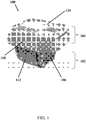
Figure 1 is a perspective view of a device for tagging an object in accordance with an embodiment of the present invention; -
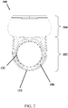
Figure 2 is a side view of a device ofFigure 1 ; -
Figure 3 is a cross sectional view of a device ofFigure 1 ; -
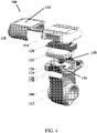
Figure 4 is an exploded view of a device ofFigure 1 ; -
Figure 5 is a block diagram of the operation of the device ofFigure 1 ; and -
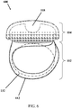
Figure 6 is a perspective view of a device for tagging an object in accordance with another embodiment of the present disclosure. - Referring to
Figure 1 and2 , there is provided an embodiment of a device for tagging an object comprising: a tag body having an engagement arrangement for engaging the tag body to the object, wherein the engagement arrangement includes at least one sensing arrangement arranged to detect a disengagement of the tag body from the object. - In this embodiment, the
device 100 for tagging an object includes anengagement arrangement 102 and atag body 104. Theengagement arrangement 102 includes two components arranged to engage thedevice 100 to a limb of an object. As shown inFigures 3 and4 , theengagement arrangement 102 includes acuff member 106 and aremovable strap 112. Preferably, thecuff member 106 is defined by a substantially C-shaped collar arranged to fit snugly with the limb of an object, such as the wrist, arm, ankle or leg of a patient. Alternatively the cuff member may be of any shape that fits with the limb of an object, including but not limited to U-shaped and O-Shaped. - In addition, the cuff member may include at least one sensing arrangement. In one example, the sensing arrangement is arranged to employ the capacitive coupling which takes human body capacitance as an input . In this example, the sensing arrangement is configured to detect a human body that has a dielectric constant different from that of air. This sensing arrangement may include a
conductive sheet 110 for electrically connecting a human body skin to thetag body 104. - Preferably, the sensing arrangement uses capacitive sensing system whereby the
conductive sheet 100 and thecuff member 106 together forms a weak capacitor. As thecuff member 106, which may compose of an insulating material with a dielectric constant, whereupon theconductive sheet 110 is integrated within thecuff member 106, the arrangement forms a capacitor of which its capacitance is altered when a limb of an object, such as a patient's wrist, arm, ankle or leg is attached to thecuff member 106 which has a different dielectric constant to thecuff member 106. By detecting or sensing this change in capacitance, the sensing arrangement is able to sense the engagement of thedevice 100 to the object. - Preferably the
cuff member 106 is made of a flexible material such as, but not limited to, rubber and silicone. Other materials such as plastic, metal etc may also be used to manufacture thecuff member 106. Additionally, the at least one portion of the sensing arrangement may be integrally formed within the cuff member. - The
engagement arrangement 102 further includes aremovable strap 112 for engaging thetag body 104 to an object. Theremovable strap 112 is preferably positioned at the outer surface of thecuff member 106 arranged to provide support to thecuff member 106 in engaging with the limb of an object. - The sensing arrangement further includes a strap sensor to be connected to the
strap 112 to detect the disengagement of the tag body from an object. Preferably, theremovable strap 112 includes a conductive member arranged to connect with the strap sensor. Alternatively, the conductive member is integrally formed within thestrap 112, and alternatively, thestrap 112 can be made with electrically conductive materials. - Referring to
Figure 4 , thetag body 104 includes an upper shell coupled to alower shell 116 which form a housing to house various components, such as aPCB 120, abattery 122, and a tightennut 126, within the housing. Alock shell 118 is arranged to secure the position of the upper shell and thelower shell 116. - The
tag body 104 further includes a printed circuit board (PCB) 120 arrange for mounting electronic components and circuits, which include an RFID arrangement for communicating with an RFID system, any other suitable communication module, such as Wi-Fi, Bluetooth, infra-red, may be mounted on thePCB 120 for communication. Preferably the RFID arrangement includes an active RFID circuit. Thetag body 104 may further include abattery 122 arranged to provide electrical power to various components of thedevice 100. This battery may be a single use battery although preferably thebattery 122 is rechargeable. A wireless charging system such as an inductive charging module may also be included to recharge thebattery 122 wirelessly. Alternatively, thetag body 104 may include a charging port for recharging thedevice 100 with a cabled recharger. - The
lower shell 116 includes anopening 124 arranged to receive a portion of a tightennut 126. In this embodiment, the tightennut 126 penetrate through theopening 124 of thelower shell 116 and is coupled to thecuff member 106. As a result of this arrangement, thecuff member 106 is securely fixed to the tag body. Aconductive ring 128 positioned in theopening 124 of the lower shell arranged to electrically connect theconductive sheet 110 or the at least one sensing arrangement to thePCB 120 such that electrical signal is configured to be transmitted from thecuff member 106 to thePCB 120 inside the housing. - As shown in this example, the lower shell further includes at least one
spring fastener 130 arranged to move within a first limiting position and a second limiting position. Thespring fastener 130 is coupled to theremovable strap 112 such that a substantiallyclose loop 132 is formed for engaging a limb of an object through theloop 132. In particular, when thespring fastener 130 is in the second limiting position, theloop 132 is substantially larger than that when thespring fastener 130 is in the first limiting position. - Referring to
Figure 6 , there is provided a device for tagging an object (not in accordance with the present invention) comprising a tag body having an engagement arrangement for engaging the tag body to the object, wherein the engagement arrangement includes at least one sensing arrangement arranged to detect a disengagement of the tag body from the object. - The
device 600 for tagging an object includes anengagement arrangement 102 and atag body 104. As shown inFigure 6 , theengagement arrangement 102 includes aremovable strap 112 for engaging thetag body 104 to an object. In this example, theremovable strap 112 is arranged to wrap around a limb of an object (such as the arm, wrist, ankle or leg of a person) and can be tightened by adjusting the slack of the strap around the limb to form a snug fit with the limb. In a similar manner, theremovable strap 112 is connected to or part of, a sensing arrangement arranged to detect the tampering or disengagement of thedevice 600 from the limb of the object by capacitive sensing or other forms of sensing arrangement. - Active RFID is a solution in logistics and supply chain management and is adopted to be used in the hospital environment to eliminate the risk of baby abduction.
- Embodiments of the present invention are advantageous in that the position of the sensors as shown in at least one embodiment is able to operate in a more sensitive manner with less error than the placement of sensors in other parts of the tag, such as in the housing or at a surface of the housing, and is thus less prone to false alarm. These embodiments are also advantageous in that the engagement arrangement is resistant to tamper, so as to further reduce the risks of abduction, when compared to simple straps without a strap sensor.
- An example embodiment of the
device 100 for tagging a new born infant with reference toFigures 1 to 5 is provided below. In the first instance, theloop 132 can be enlarged by pulling thestrap 112 such that the at least one spring fastener move from the first limiting position to the second limiting position, then thedevice 100 can be engaged to a limb of a new born infant through theloop 132, by releasing the spring fastener back to the first limiting position, theloop 132 restore to a smaller dimension. As a result thestrap 112 applies an inward supportive force to thecuff member 106, such that the inner wall of thecuff member 106 attaches firmly to the skin of the limb of the new born infant, and the attachment is detected by theconductive sheet 110 on thecuff member 106. The flexible C-shaped collar structure helps to improve the attachment of thecuff member 106 to the skin of the limb and hence improve the accuracy of the detection of the cuff sensor over an O-shaped collar design. - When the
tag body 104 is disengaged from the limb of the new born infant, the conductive member of thestrap 112 is arranged to disconnect from the strap sensor, and the disconnection between the conductive member and the strap sensor is detected by the strap sensor. In addition, the detachment of thecuff member 106 from the skin of the limb of the new born infant is detected by the cuff sensor. - Referring to
Figure 5 , when thetagging device 100 and the RFID system (not shown) are in operation, thetag body 104 is arranged to process the sensing signal fed from thestrap sensor 502, the cuff sensor 504 (which may be capacitive and thebattery sensor 506. Upon a manipulation to the engagement arrangement, which includes removing the attached device from the skin, disengaging the engaged device from the limb, and damaging of thestrap 112, is detected by any of the sensing arrangement, a detection signal will be processed by a transceiver with amicrocontroller 508 and the active RFID circuit will transmit a signal via anantenna 510 to the RFID system which can alert a user of the tagging device. In addition, thebattery sensor 506 is arranged to detect the operating voltage of the battery such that the active RFID circuit can transmit a signal to the RFID system to alert a user when the battery level becomes low and requires attention such as recharging thebattery 512 with a chargingcircuit 514. - On the
top surface 134 of thelock shell 118, a user can write or label information including text, images, symbols, barcodes or any combination thereof, to help identifying the tagging device or the object with the device engaged. - The tagging device can be engaged to any limb of a living creature or any object. In some embodiments, the tag can be arranged for engagement to an object other than an infant for tagging or tracking of the object. These objects may include adult or child patients, animals or inanimate objects such as bodies, animal carcasses, furniture, vehicles, etc.
- It will be appreciated by persons skilled in the art that numerous variations and/or modifications may be made to the invention as shown in the specific embodiments as broadly described. The present embodiments are, therefore, to be considered in all respects as illustrative and not restrictive.
- Any reference to prior art contained herein is not to be taken as an admission that the information is common general knowledge, unless otherwise indicated.
Claims (11)
- A device (100) for tagging an object, comprising a tag body (104) having an engagement arrangement (102) for engaging the tag body to the object, wherein the engagement arrangement includes at least one sensing arrangement arranged to detect a disengagement of the tag body (104) from the object, wherein:the engagement arrangement includes a removable strap (112) for engaging the tag body (104) to the object;the at least one sensing arrangement includes a strap sensor (502) arranged to be connected to the removable strap (112) to detect the disengagement of the tag body (104) from the object;the removable strap (112) includes a conductive member arranged to connect with the strap sensor (502); andthe conductive member is further arranged to disconnect from the strap sensor (502) when the tag body (104) is disengaged from the object, characterized in that:
the engagement arrangement further includes a cuff member (106) arranged to fit snugly with a limb of the object to engage the tag body to the object; and the at least one sensing arrangement further includes a cuff sensor (504) disposed adjacent to the cuff member (106), the cuff sensor (504) arranged to detect a disengagement of the cuff member (106) from the limb of the object. - A device (100) in accordance with claim 1, wherein the at least one sensing arrangement is arranged to detect a manipulation with the engagement arrangement (102).
- A device (100) in accordance with claims 1 or 2, wherein the manipulation to the engagement arrangement (102) includes removing, disengaging or damaging the engagement arrangement (102).
- A device (100) in accordance with any one of the preceding claims, wherein the cuff sensor (504) is arranged to detect a disengagement of the cuff member (106) from the limb of the object by capacitive sensing.
- A device (100) in accordance with any one of the preceding claims, wherein the cuff member (106) is defined by a substantially C-shaped collar.
- A device (100) in accordance with any one of the preceding claims, wherein the strap sensor (502) is arranged to detect a tampering of the engagement arrangement.
- A device (100) in accordance with any one of the preceding claims, wherein at least one portion of the cuff sensor (504) is integrally formed within the cuff member (106).
- A device (100) in accordance with any one of the preceding claims, wherein the cuff sensor (504) includes a conductive sheet (110) arranged to detect the disengagement of the cuff member (106) from the limb of the object.
- A device (100) in accordance with claim 8, wherein the conductive sheet (110) is integrated into the cuff member (106).
- A device (100) in accordance with any one of the preceding claims, wherein the strap sensor (502) is arranged to detect a disconnection between the conductive member and the strap sensor (502).
- A device (100) in accordance with any one of the preceding claims, wherein the tag body (104) further includes a RFID arrangement for communicating with a RFID system.
Applications Claiming Priority (1)
| Application Number | Priority Date | Filing Date | Title |
|---|---|---|---|
| PCT/CN2013/071569 WO2014121517A1 (en) | 2013-02-08 | 2013-02-08 | Device for tagging object |
Publications (3)
| Publication Number | Publication Date |
|---|---|
| EP2954502A1 EP2954502A1 (en) | 2015-12-16 |
| EP2954502A4 EP2954502A4 (en) | 2016-10-19 |
| EP2954502B1 true EP2954502B1 (en) | 2019-08-28 |
Family
ID=51299220
Family Applications (1)
| Application Number | Title | Priority Date | Filing Date |
|---|---|---|---|
| EP13874810.8A Active EP2954502B1 (en) | 2013-02-08 | 2013-02-08 | Device for tagging object |
Country Status (4)
| Country | Link |
|---|---|
| US (1) | US9666053B2 (en) |
| EP (1) | EP2954502B1 (en) |
| CN (1) | CN105144255B (en) |
| WO (1) | WO2014121517A1 (en) |
Families Citing this family (2)
| Publication number | Priority date | Publication date | Assignee | Title |
|---|---|---|---|---|
| US11288467B2 (en) | 2017-03-15 | 2022-03-29 | Hong Kong R&D Centre for Logistics and Supply Chain Management Enabling Technologies Limited | Wearable non-contact communication device |
| US11582948B2 (en) * | 2020-07-21 | 2023-02-21 | Garrity Power Services Llc | Cattle tracking system |
Citations (3)
| Publication number | Priority date | Publication date | Assignee | Title |
|---|---|---|---|---|
| US4918432A (en) * | 1988-09-27 | 1990-04-17 | B. I. Incorporated | House arrest monitoring system |
| US5075670A (en) * | 1990-08-01 | 1991-12-24 | Digital Products Corporation | Personnel monitoring tag with tamper detection and secure reset |
| US20030174059A1 (en) * | 2002-03-12 | 2003-09-18 | Michael Reeves | Home detention system |
Family Cites Families (14)
| Publication number | Priority date | Publication date | Assignee | Title |
|---|---|---|---|---|
| US5006830A (en) * | 1989-10-16 | 1991-04-09 | Rebecca Merritt | Method and device for deterring the unauthorized removal of a newborn from a defined area |
| US6104295A (en) * | 1998-07-20 | 2000-08-15 | Versus Technology, Inc. | Electronic band tag and method of storing ID information therein |
| JP3778272B2 (en) * | 2001-09-06 | 2006-05-24 | 株式会社ミネルバ | Medical management tag |
| NO319077B1 (en) * | 2002-03-21 | 2005-06-13 | Telenor Asa | Traditional animals |
| FR2848324B3 (en) * | 2002-12-06 | 2005-01-21 | Lionel Prat | DISPLACEMENT FLIGHT SECURITY DEVICE OF THE LABEL TYPE |
| US7132944B1 (en) * | 2003-06-06 | 2006-11-07 | Innovative Control Systems, Inc. | Microprocessor controlled security tag |
| US7084764B2 (en) * | 2004-04-15 | 2006-08-01 | Secure Care Products, Inc. | System and method for monitoring location of an object |
| US20060242875A1 (en) * | 2005-04-14 | 2006-11-02 | Anita Wilson | Pediatric patient identification wristband tag |
| US7205890B2 (en) | 2005-05-17 | 2007-04-17 | Pro Tech Monitoring, Inc. | System, method and apparatus for locating and controlling objects |
| WO2007139205A1 (en) * | 2006-05-31 | 2007-12-06 | Semiconductor Energy Laboratory Co., Ltd. | Semiconductor device and ic label, ic tag, and ic card having the same |
| US8375522B2 (en) * | 2008-12-02 | 2013-02-19 | Rondish Co. Ltd. | Strap monitoring system |
| WO2010074683A1 (en) * | 2008-12-23 | 2010-07-01 | Analogic Corporation | Blood pressure cuff |
| US8410926B1 (en) | 2010-05-07 | 2013-04-02 | Rf Technologies, Inc. | Alarm for security tag |
| CN202632319U (en) * | 2012-05-11 | 2012-12-26 | 无锡市天业智能科技有限公司 | Internet-of-things newborn infant monitoring system |
-
2013
- 2013-02-08 US US14/766,819 patent/US9666053B2/en active Active
- 2013-02-08 EP EP13874810.8A patent/EP2954502B1/en active Active
- 2013-02-08 WO PCT/CN2013/071569 patent/WO2014121517A1/en not_active Ceased
- 2013-02-08 CN CN201380075416.3A patent/CN105144255B/en active Active
Patent Citations (3)
| Publication number | Priority date | Publication date | Assignee | Title |
|---|---|---|---|---|
| US4918432A (en) * | 1988-09-27 | 1990-04-17 | B. I. Incorporated | House arrest monitoring system |
| US5075670A (en) * | 1990-08-01 | 1991-12-24 | Digital Products Corporation | Personnel monitoring tag with tamper detection and secure reset |
| US20030174059A1 (en) * | 2002-03-12 | 2003-09-18 | Michael Reeves | Home detention system |
Also Published As
| Publication number | Publication date |
|---|---|
| US20150379850A1 (en) | 2015-12-31 |
| EP2954502A4 (en) | 2016-10-19 |
| WO2014121517A1 (en) | 2014-08-14 |
| CN105144255B (en) | 2018-02-27 |
| HK1214022A1 (en) | 2016-07-15 |
| CN105144255A (en) | 2015-12-09 |
| US9666053B2 (en) | 2017-05-30 |
| EP2954502A1 (en) | 2015-12-16 |
Similar Documents
| Publication | Publication Date | Title |
|---|---|---|
| US7733233B2 (en) | Methods and systems for monitoring position and movement of human beings | |
| US8410926B1 (en) | Alarm for security tag | |
| US20020124295A1 (en) | Clothing apparatus, carrier for a biophysical sensor, and patient alarm system | |
| US9572528B1 (en) | Monitor for SIDS research and prevention | |
| US20010032059A1 (en) | Attitude indicator and activity monitoring device | |
| US20070038155A1 (en) | Attitude Indicator And Activity Monitoring Device | |
| US20140323818A1 (en) | Wireless Physiological Monitoring Device | |
| US20120319835A1 (en) | Device and Method for Electronic Body Monitoring, more particularly for Infants | |
| US20210183504A1 (en) | Patient bed exit prediction | |
| GB2512575A (en) | Apparatus and system for non-invasive incontinence detection, analysis and transmission | |
| US9666053B2 (en) | Device for tagging an object | |
| CN108903910A (en) | A kind of intelligent spire lamella of automatic transmission information | |
| US20200029901A1 (en) | Contactless measurement, monitoring and communication of bodily functions of infants and other helpless individuals | |
| CN101425149B (en) | Device and method for monitoring personal action safety by using electronic tag tape | |
| HK1214022B (en) | Device for tagging object | |
| AU4871999A (en) | Person monitoring apparatus | |
| US10028118B2 (en) | Intelligent security identification apparatus and system | |
| CN217365834U (en) | All-directional nursing device | |
| CN213664016U (en) | A kind of medical children's bracelet and medical intelligent system | |
| KR101861613B1 (en) | Sensor device and operation method of sensor device, and newborn baby vomit detecting system using sensor device | |
| US10470669B2 (en) | Contactless measurement, monitoring and communication of bodily functions of infants and other helpless individuals | |
| Mukhopadhyay et al. | Sensors and robotic environment for care of the elderly | |
| US20200177848A1 (en) | Monitoring system for providing both visual and non-visual data | |
| GB2530118A (en) | Vital pad + | |
| TWM488422U (en) | Low power consumption comprehensive safety status monitoring and caring system |
Legal Events
| Date | Code | Title | Description |
|---|---|---|---|
| PUAI | Public reference made under article 153(3) epc to a published international application that has entered the european phase |
Free format text: ORIGINAL CODE: 0009012 |
|
| 17P | Request for examination filed |
Effective date: 20150807 |
|
| AK | Designated contracting states |
Kind code of ref document: A1 Designated state(s): AL AT BE BG CH CY CZ DE DK EE ES FI FR GB GR HR HU IE IS IT LI LT LU LV MC MK MT NL NO PL PT RO RS SE SI SK SM TR |
|
| AX | Request for extension of the european patent |
Extension state: BA ME |
|
| DAX | Request for extension of the european patent (deleted) | ||
| REG | Reference to a national code |
Ref country code: HK Ref legal event code: DE Ref document number: 1214022 Country of ref document: HK |
|
| A4 | Supplementary search report drawn up and despatched |
Effective date: 20160915 |
|
| RIC1 | Information provided on ipc code assigned before grant |
Ipc: A61B 90/90 20160101AFI20160909BHEP Ipc: A61B 90/98 20160101ALI20160909BHEP Ipc: G08B 21/02 20060101ALI20160909BHEP Ipc: G08B 23/00 20060101ALI20160909BHEP |
|
| STAA | Information on the status of an ep patent application or granted ep patent |
Free format text: STATUS: EXAMINATION IS IN PROGRESS |
|
| 17Q | First examination report despatched |
Effective date: 20180319 |
|
| REG | Reference to a national code |
Ref country code: DE Ref legal event code: R079 Ref document number: 602013059880 Country of ref document: DE Free format text: PREVIOUS MAIN CLASS: G08B0023000000 Ipc: A61B0090900000 |
|
| GRAP | Despatch of communication of intention to grant a patent |
Free format text: ORIGINAL CODE: EPIDOSNIGR1 |
|
| STAA | Information on the status of an ep patent application or granted ep patent |
Free format text: STATUS: GRANT OF PATENT IS INTENDED |
|
| RIC1 | Information provided on ipc code assigned before grant |
Ipc: A61B 5/00 20060101ALN20190228BHEP Ipc: A61B 90/90 20160101AFI20190228BHEP Ipc: G08B 21/02 20060101ALN20190228BHEP |
|
| INTG | Intention to grant announced |
Effective date: 20190320 |
|
| RAP1 | Party data changed (applicant data changed or rights of an application transferred) |
Owner name: HONG KONG R&D CENTRE FOR LOGISTICS AND SUPPLY CHAI |
|
| GRAS | Grant fee paid |
Free format text: ORIGINAL CODE: EPIDOSNIGR3 |
|
| GRAA | (expected) grant |
Free format text: ORIGINAL CODE: 0009210 |
|
| STAA | Information on the status of an ep patent application or granted ep patent |
Free format text: STATUS: THE PATENT HAS BEEN GRANTED |
|
| AK | Designated contracting states |
Kind code of ref document: B1 Designated state(s): AL AT BE BG CH CY CZ DE DK EE ES FI FR GB GR HR HU IE IS IT LI LT LU LV MC MK MT NL NO PL PT RO RS SE SI SK SM TR |
|
| REG | Reference to a national code |
Ref country code: GB Ref legal event code: FG4D |
|
| REG | Reference to a national code |
Ref country code: CH Ref legal event code: EP |
|
| REG | Reference to a national code |
Ref country code: AT Ref legal event code: REF Ref document number: 1171436 Country of ref document: AT Kind code of ref document: T Effective date: 20190915 |
|
| REG | Reference to a national code |
Ref country code: IE Ref legal event code: FG4D |
|
| REG | Reference to a national code |
Ref country code: DE Ref legal event code: R096 Ref document number: 602013059880 Country of ref document: DE |
|
| REG | Reference to a national code |
Ref country code: NL Ref legal event code: MP Effective date: 20190828 |
|
| REG | Reference to a national code |
Ref country code: LT Ref legal event code: MG4D |
|
| PG25 | Lapsed in a contracting state [announced via postgrant information from national office to epo] |
Ref country code: PT Free format text: LAPSE BECAUSE OF FAILURE TO SUBMIT A TRANSLATION OF THE DESCRIPTION OR TO PAY THE FEE WITHIN THE PRESCRIBED TIME-LIMIT Effective date: 20191230 Ref country code: LT Free format text: LAPSE BECAUSE OF FAILURE TO SUBMIT A TRANSLATION OF THE DESCRIPTION OR TO PAY THE FEE WITHIN THE PRESCRIBED TIME-LIMIT Effective date: 20190828 Ref country code: HR Free format text: LAPSE BECAUSE OF FAILURE TO SUBMIT A TRANSLATION OF THE DESCRIPTION OR TO PAY THE FEE WITHIN THE PRESCRIBED TIME-LIMIT Effective date: 20190828 Ref country code: NO Free format text: LAPSE BECAUSE OF FAILURE TO SUBMIT A TRANSLATION OF THE DESCRIPTION OR TO PAY THE FEE WITHIN THE PRESCRIBED TIME-LIMIT Effective date: 20191128 Ref country code: SE Free format text: LAPSE BECAUSE OF FAILURE TO SUBMIT A TRANSLATION OF THE DESCRIPTION OR TO PAY THE FEE WITHIN THE PRESCRIBED TIME-LIMIT Effective date: 20190828 Ref country code: FI Free format text: LAPSE BECAUSE OF FAILURE TO SUBMIT A TRANSLATION OF THE DESCRIPTION OR TO PAY THE FEE WITHIN THE PRESCRIBED TIME-LIMIT Effective date: 20190828 Ref country code: BG Free format text: LAPSE BECAUSE OF FAILURE TO SUBMIT A TRANSLATION OF THE DESCRIPTION OR TO PAY THE FEE WITHIN THE PRESCRIBED TIME-LIMIT Effective date: 20191128 Ref country code: NL Free format text: LAPSE BECAUSE OF FAILURE TO SUBMIT A TRANSLATION OF THE DESCRIPTION OR TO PAY THE FEE WITHIN THE PRESCRIBED TIME-LIMIT Effective date: 20190828 |
|
| PG25 | Lapsed in a contracting state [announced via postgrant information from national office to epo] |
Ref country code: IS Free format text: LAPSE BECAUSE OF FAILURE TO SUBMIT A TRANSLATION OF THE DESCRIPTION OR TO PAY THE FEE WITHIN THE PRESCRIBED TIME-LIMIT Effective date: 20191228 Ref country code: RS Free format text: LAPSE BECAUSE OF FAILURE TO SUBMIT A TRANSLATION OF THE DESCRIPTION OR TO PAY THE FEE WITHIN THE PRESCRIBED TIME-LIMIT Effective date: 20190828 Ref country code: AL Free format text: LAPSE BECAUSE OF FAILURE TO SUBMIT A TRANSLATION OF THE DESCRIPTION OR TO PAY THE FEE WITHIN THE PRESCRIBED TIME-LIMIT Effective date: 20190828 Ref country code: LV Free format text: LAPSE BECAUSE OF FAILURE TO SUBMIT A TRANSLATION OF THE DESCRIPTION OR TO PAY THE FEE WITHIN THE PRESCRIBED TIME-LIMIT Effective date: 20190828 Ref country code: ES Free format text: LAPSE BECAUSE OF FAILURE TO SUBMIT A TRANSLATION OF THE DESCRIPTION OR TO PAY THE FEE WITHIN THE PRESCRIBED TIME-LIMIT Effective date: 20190828 Ref country code: GR Free format text: LAPSE BECAUSE OF FAILURE TO SUBMIT A TRANSLATION OF THE DESCRIPTION OR TO PAY THE FEE WITHIN THE PRESCRIBED TIME-LIMIT Effective date: 20191129 |
|
| REG | Reference to a national code |
Ref country code: AT Ref legal event code: MK05 Ref document number: 1171436 Country of ref document: AT Kind code of ref document: T Effective date: 20190828 |
|
| PG25 | Lapsed in a contracting state [announced via postgrant information from national office to epo] |
Ref country code: TR Free format text: LAPSE BECAUSE OF FAILURE TO SUBMIT A TRANSLATION OF THE DESCRIPTION OR TO PAY THE FEE WITHIN THE PRESCRIBED TIME-LIMIT Effective date: 20190828 |
|
| PG25 | Lapsed in a contracting state [announced via postgrant information from national office to epo] |
Ref country code: AT Free format text: LAPSE BECAUSE OF FAILURE TO SUBMIT A TRANSLATION OF THE DESCRIPTION OR TO PAY THE FEE WITHIN THE PRESCRIBED TIME-LIMIT Effective date: 20190828 Ref country code: DK Free format text: LAPSE BECAUSE OF FAILURE TO SUBMIT A TRANSLATION OF THE DESCRIPTION OR TO PAY THE FEE WITHIN THE PRESCRIBED TIME-LIMIT Effective date: 20190828 Ref country code: PL Free format text: LAPSE BECAUSE OF FAILURE TO SUBMIT A TRANSLATION OF THE DESCRIPTION OR TO PAY THE FEE WITHIN THE PRESCRIBED TIME-LIMIT Effective date: 20190828 Ref country code: RO Free format text: LAPSE BECAUSE OF FAILURE TO SUBMIT A TRANSLATION OF THE DESCRIPTION OR TO PAY THE FEE WITHIN THE PRESCRIBED TIME-LIMIT Effective date: 20190828 Ref country code: EE Free format text: LAPSE BECAUSE OF FAILURE TO SUBMIT A TRANSLATION OF THE DESCRIPTION OR TO PAY THE FEE WITHIN THE PRESCRIBED TIME-LIMIT Effective date: 20190828 Ref country code: IT Free format text: LAPSE BECAUSE OF FAILURE TO SUBMIT A TRANSLATION OF THE DESCRIPTION OR TO PAY THE FEE WITHIN THE PRESCRIBED TIME-LIMIT Effective date: 20190828 |
|
| PG25 | Lapsed in a contracting state [announced via postgrant information from national office to epo] |
Ref country code: SM Free format text: LAPSE BECAUSE OF FAILURE TO SUBMIT A TRANSLATION OF THE DESCRIPTION OR TO PAY THE FEE WITHIN THE PRESCRIBED TIME-LIMIT Effective date: 20190828 Ref country code: IS Free format text: LAPSE BECAUSE OF FAILURE TO SUBMIT A TRANSLATION OF THE DESCRIPTION OR TO PAY THE FEE WITHIN THE PRESCRIBED TIME-LIMIT Effective date: 20200224 Ref country code: CZ Free format text: LAPSE BECAUSE OF FAILURE TO SUBMIT A TRANSLATION OF THE DESCRIPTION OR TO PAY THE FEE WITHIN THE PRESCRIBED TIME-LIMIT Effective date: 20190828 Ref country code: SK Free format text: LAPSE BECAUSE OF FAILURE TO SUBMIT A TRANSLATION OF THE DESCRIPTION OR TO PAY THE FEE WITHIN THE PRESCRIBED TIME-LIMIT Effective date: 20190828 |
|
| REG | Reference to a national code |
Ref country code: DE Ref legal event code: R097 Ref document number: 602013059880 Country of ref document: DE |
|
| PLBE | No opposition filed within time limit |
Free format text: ORIGINAL CODE: 0009261 |
|
| STAA | Information on the status of an ep patent application or granted ep patent |
Free format text: STATUS: NO OPPOSITION FILED WITHIN TIME LIMIT |
|
| PG2D | Information on lapse in contracting state deleted |
Ref country code: IS |
|
| 26N | No opposition filed |
Effective date: 20200603 |
|
| PG25 | Lapsed in a contracting state [announced via postgrant information from national office to epo] |
Ref country code: SI Free format text: LAPSE BECAUSE OF FAILURE TO SUBMIT A TRANSLATION OF THE DESCRIPTION OR TO PAY THE FEE WITHIN THE PRESCRIBED TIME-LIMIT Effective date: 20190828 |
|
| REG | Reference to a national code |
Ref country code: CH Ref legal event code: PL |
|
| REG | Reference to a national code |
Ref country code: BE Ref legal event code: MM Effective date: 20200229 |
|
| PG25 | Lapsed in a contracting state [announced via postgrant information from national office to epo] |
Ref country code: MC Free format text: LAPSE BECAUSE OF FAILURE TO SUBMIT A TRANSLATION OF THE DESCRIPTION OR TO PAY THE FEE WITHIN THE PRESCRIBED TIME-LIMIT Effective date: 20190828 Ref country code: LU Free format text: LAPSE BECAUSE OF NON-PAYMENT OF DUE FEES Effective date: 20200208 |
|
| PG25 | Lapsed in a contracting state [announced via postgrant information from national office to epo] |
Ref country code: LI Free format text: LAPSE BECAUSE OF NON-PAYMENT OF DUE FEES Effective date: 20200229 Ref country code: CH Free format text: LAPSE BECAUSE OF NON-PAYMENT OF DUE FEES Effective date: 20200229 |
|
| PG25 | Lapsed in a contracting state [announced via postgrant information from national office to epo] |
Ref country code: IE Free format text: LAPSE BECAUSE OF NON-PAYMENT OF DUE FEES Effective date: 20200208 |
|
| PG25 | Lapsed in a contracting state [announced via postgrant information from national office to epo] |
Ref country code: BE Free format text: LAPSE BECAUSE OF NON-PAYMENT OF DUE FEES Effective date: 20200229 |
|
| PG25 | Lapsed in a contracting state [announced via postgrant information from national office to epo] |
Ref country code: MT Free format text: LAPSE BECAUSE OF FAILURE TO SUBMIT A TRANSLATION OF THE DESCRIPTION OR TO PAY THE FEE WITHIN THE PRESCRIBED TIME-LIMIT Effective date: 20190828 Ref country code: CY Free format text: LAPSE BECAUSE OF FAILURE TO SUBMIT A TRANSLATION OF THE DESCRIPTION OR TO PAY THE FEE WITHIN THE PRESCRIBED TIME-LIMIT Effective date: 20190828 |
|
| PG25 | Lapsed in a contracting state [announced via postgrant information from national office to epo] |
Ref country code: MK Free format text: LAPSE BECAUSE OF FAILURE TO SUBMIT A TRANSLATION OF THE DESCRIPTION OR TO PAY THE FEE WITHIN THE PRESCRIBED TIME-LIMIT Effective date: 20190828 |
|
| PGFP | Annual fee paid to national office [announced via postgrant information from national office to epo] |
Ref country code: DE Payment date: 20240130 Year of fee payment: 12 Ref country code: GB Payment date: 20240201 Year of fee payment: 12 |
|
| PGFP | Annual fee paid to national office [announced via postgrant information from national office to epo] |
Ref country code: FR Payment date: 20240126 Year of fee payment: 12 |
|
| REG | Reference to a national code |
Ref country code: DE Ref legal event code: R119 Ref document number: 602013059880 Country of ref document: DE |
|
| GBPC | Gb: european patent ceased through non-payment of renewal fee |
Effective date: 20250208 |
|
| PG25 | Lapsed in a contracting state [announced via postgrant information from national office to epo] |
Ref country code: DE Free format text: LAPSE BECAUSE OF NON-PAYMENT OF DUE FEES Effective date: 20250902 |
|
| PG25 | Lapsed in a contracting state [announced via postgrant information from national office to epo] |
Ref country code: GB Free format text: LAPSE BECAUSE OF NON-PAYMENT OF DUE FEES Effective date: 20250208 |
|
| PG25 | Lapsed in a contracting state [announced via postgrant information from national office to epo] |
Ref country code: FR Free format text: LAPSE BECAUSE OF NON-PAYMENT OF DUE FEES Effective date: 20250228 |