EP2954416B1 - Systems and methods for error correction in quantum computation - Google Patents
Systems and methods for error correction in quantum computation Download PDFInfo
- Publication number
- EP2954416B1 EP2954416B1 EP14749223.5A EP14749223A EP2954416B1 EP 2954416 B1 EP2954416 B1 EP 2954416B1 EP 14749223 A EP14749223 A EP 14749223A EP 2954416 B1 EP2954416 B1 EP 2954416B1
- Authority
- EP
- European Patent Office
- Prior art keywords
- qubits
- quantum processor
- replica
- problem formulation
- quantum
- Prior art date
- Legal status (The legal status is an assumption and is not a legal conclusion. Google has not performed a legal analysis and makes no representation as to the accuracy of the status listed.)
- Active
Links
Images


Classifications
-
- G—PHYSICS
- G06—COMPUTING OR CALCULATING; COUNTING
- G06F—ELECTRIC DIGITAL DATA PROCESSING
- G06F11/00—Error detection; Error correction; Monitoring
- G06F11/07—Responding to the occurrence of a fault, e.g. fault tolerance
- G06F11/0703—Error or fault processing not based on redundancy, i.e. by taking additional measures to deal with the error or fault not making use of redundancy in operation, in hardware, or in data representation
- G06F11/0706—Error or fault processing not based on redundancy, i.e. by taking additional measures to deal with the error or fault not making use of redundancy in operation, in hardware, or in data representation the processing taking place on a specific hardware platform or in a specific software environment
- G06F11/0721—Error or fault processing not based on redundancy, i.e. by taking additional measures to deal with the error or fault not making use of redundancy in operation, in hardware, or in data representation the processing taking place on a specific hardware platform or in a specific software environment within a central processing unit [CPU]
- G06F11/0724—Error or fault processing not based on redundancy, i.e. by taking additional measures to deal with the error or fault not making use of redundancy in operation, in hardware, or in data representation the processing taking place on a specific hardware platform or in a specific software environment within a central processing unit [CPU] in a multiprocessor or a multi-core unit
-
- G—PHYSICS
- G06—COMPUTING OR CALCULATING; COUNTING
- G06F—ELECTRIC DIGITAL DATA PROCESSING
- G06F11/00—Error detection; Error correction; Monitoring
- G06F11/07—Responding to the occurrence of a fault, e.g. fault tolerance
- G06F11/14—Error detection or correction of the data by redundancy in operations
- G06F11/1479—Generic software techniques for error detection or fault masking
- G06F11/1492—Generic software techniques for error detection or fault masking using run-time replication performed by the application software, e.g. N-modular type
-
- G—PHYSICS
- G06—COMPUTING OR CALCULATING; COUNTING
- G06F—ELECTRIC DIGITAL DATA PROCESSING
- G06F11/00—Error detection; Error correction; Monitoring
- G06F11/07—Responding to the occurrence of a fault, e.g. fault tolerance
- G06F11/08—Error detection or correction by redundancy in data representation, e.g. by using checking codes
- G06F11/10—Adding special bits or symbols to the coded information, e.g. parity check, casting out 9's or 11's
-
- G—PHYSICS
- G06—COMPUTING OR CALCULATING; COUNTING
- G06N—COMPUTING ARRANGEMENTS BASED ON SPECIFIC COMPUTATIONAL MODELS
- G06N10/00—Quantum computing, i.e. information processing based on quantum-mechanical phenomena
- G06N10/60—Quantum algorithms, e.g. based on quantum optimisation, quantum Fourier or Hadamard transforms
-
- G—PHYSICS
- G06—COMPUTING OR CALCULATING; COUNTING
- G06N—COMPUTING ARRANGEMENTS BASED ON SPECIFIC COMPUTATIONAL MODELS
- G06N10/00—Quantum computing, i.e. information processing based on quantum-mechanical phenomena
- G06N10/70—Quantum error correction, detection or prevention, e.g. surface codes or magic state distillation
Definitions
- the present systems and methods generally relate to error correction in quantum computation and particularly relate to error correction in implementations of adiabatic quantum computation and quantum annealing.
- Adiabatic quantum computation typically involves evolving a system from a known initial Hamiltonian (the Hamiltonian being an operator whose eigenvalues are the allowed energies of the system) to a final Hamiltonian by gradually changing the Hamiltonian.
- the system is typically initialized in a ground state of the initial Hamiltonian H i and the goal is to evolve the system in such a way that the system ends up in a ground state of the final Hamiltonian H f at the end of the evolution. If the evolution is too fast, then the system can be excited to a higher energy state, such as the first excited state.
- an "adiabatic" evolution is considered to be an evolution that satisfies the adiabatic condition: s ⁇ ⁇ 1
- 0 ⁇ ⁇ g 2 s
- ⁇ is the time derivative of s
- g ( s ) is the difference in energy between the ground state and first excited state of the system (also referred to herein as the "gap size") as a function of s, and ⁇ is a coefficient much less than 1.
- the evolution process in adiabatic quantum computing may sometimes be referred to as annealing.
- the rate that s changes sometimes referred to as an evolution or annealing schedule, is normally slow enough that the system is always in the instantaneous ground state of the evolution Hamiltonian during the evolution, and transitions at anti-crossings ( i.e., when the gap size is smallest) are avoided.
- Further details on adiabatic quantum computing systems, methods, and apparatus are described in, for example, US Patent 7,135,701 and US Patent 7,418,283 .
- Quantum annealing is a computation method that may be used to find a low-energy state, typically preferably the ground state, of a system. Somewhat similar in concept to classical annealing, the method relies on the underlying principle that natural systems tend towards lower energy states because lower energy states are more stable. However, while classical annealing uses classical thermal fluctuations to guide a system to its global energy minimum, quantum annealing may use quantum effects, such as quantum tunneling, to reach a global energy minimum more accurately and/or more quickly than classical annealing.
- a hard problem such as a combinatorial optimization problem
- a system Hamiltonian e.g., the Hamiltonian of an Ising spin glass
- quantum annealing may be used to find the solution to such a hard problem.
- Adiabatic quantum computation may be considered a special case of quantum annealing for which the system, ideally, begins and remains in its ground state throughout an adiabatic evolution.
- quantum annealing systems and methods may generally be implemented on an adiabatic quantum computer, and vice versa.
- any reference to quantum annealing is intended to encompass adiabatic quantum computation unless the context requires otherwise.
- Quantum annealing uses quantum mechanics as a source of disorder during the annealing process.
- the optimization problem is encoded in a Hamiltonian H P , and the algorithm introduces strong quantum fluctuations by adding a disordering Hamiltonian H D that does not commute with H P .
- the disorder is slowly removed by removing H D (i.e., reducing ⁇ ).
- quantum annealing is similar to adiabatic quantum computation in that the system starts with an initial Hamiltonian and evolves through an evolution Hamiltonian to a final "problem" Hamiltonian H P whose ground state encodes a solution to the problem. If the evolution is slow enough, the system will typically settle in the global minimum (i.e., the exact solution), or in a local minimum close to the exact solution.
- the performance of the computation may be assessed via the residual energy (distance from exact solution using the objective function) versus evolution time.
- the computation time is the time required to generate a residual energy below some acceptable threshold value.
- H P may encode an optimization problem and therefore H P may be diagonal in the subspace of the qubits that encode the solution, but the system does not necessarily stay in the ground state at all times.
- the energy landscape of H P may be crafted so that its global minimum is the answer to the problem to be solved, and low-lying local minima are good approximations.
- quantum annealing may follow a defined schedule known as an annealing schedule. Unlike traditional forms of adiabatic quantum computation where the system begins and remains in its ground state throughout the evolution, in quantum annealing the system may not remain in its ground state throughout the entire annealing schedule. As such, quantum annealing may be implemented as a heuristic technique, where low-energy states with energy near that of the ground state may provide approximate solutions to the problem.
- a quantum processor may take the form of a superconducting quantum processor.
- a superconducting quantum processor may include a number of qubits and associated local bias devices, for instance two or more superconducting qubits.
- a superconducting quantum processor may also employ coupling devices (i.e., "couplers") providing communicative coupling between qubits.
- Patent publication US 8,234,103 B2 discloses devices, methods and articles that allow communications between qubits to provide an architecture for universal adiabatic quantum computation.
- the architecture includes a first coupled basis A 1 B 1 and a second coupled basis A 2 B 2 that does not commute with the first basis A 1 B 1 .
- a quantum processor may be summarized as including a first set of qubits and a first set of coupling devices providing communicative coupling between qubits in the first set of qubits; a first set of replica qubits and a first set of replica coupling devices providing communicative coupling between the first set of replica qubits, wherein for each qubit in the first set of qubits a corresponding replica qubit exists in the first set of replica qubits, and for each coupling device in the first set of coupling devices a replica coupling device exists in the first set of replica coupling devices; and a second set of coupling devices, wherein each coupling device in the second set of coupling devices provides communicative coupling between a qubit in the first set of qubits and the corresponding replica qubit in the first set of replica qubits.
- the quantum processor may include a superconducting quantum processor, the qubits may include superconducting qubits, and the coupling devices may include superconducting coupling devices.
- quantum processors such as quantum devices, coupling devices, and control systems including microprocessors, drive circuitry and nontransitory computer- or processor-readable media such as nonvolatile memory for instance read only memory (ROM), electronically erasable programmable ROM (EEPROM) or FLASH memory, etc., or volatile memory for instance static or dynamic random access memory (ROM) have not been shown or described in detail to avoid unnecessarily obscuring descriptions of the embodiments of the present systems and methods.
- ROM read only memory
- EEPROM electronically erasable programmable ROM
- FLASH memory FLASH memory
- volatile memory static or dynamic random access memory
- the various embodiments described herein provide systems and methods for error correction in quantum computation. More specifically, the various embodiments described herein provide systems and methods for implementing error correction protocols in quantum processors designed to perform adiabatic quantum computation and/or quantum annealing algorithms.
- a superconducting quantum processor designed to perform adiabatic quantum computation and/or quantum annealing is used in the description that follows.
- quantum processor hardware e.g., superconducting, photonic, ion-trap, quantum dot, topological, etc.
- quantum algorithm(s) e.g., adiabatic quantum computation, quantum annealing, gate/circuit-based quantum computing, etc.
- H ln is the initial Hamiltonian
- H f is the final or "problem" Hamiltonian
- H e is the evolution or instantaneous Hamiltonian
- s is the evolution coefficient which controls the rate of evolution.
- s may vary from 0 to 1 with time t as s ( t ) .
- AQC adiabatic quantum computation
- N represents the number of qubits
- ⁇ i x is the Pauli x -matrix for the i th qubit
- ⁇ i is the single qubit tunnel splitting induced in the i th qubit.
- the ⁇ i x terms are examples of "off-diagonal" terms.
- N represents the number of qubits
- ⁇ i z is the Pauli z -matrix for the ⁇ th qubit
- h i and J i,j are dimensionless local fields for the qubits
- couplings between qubits and ⁇ is some characteristic energy scale for H f .
- the ⁇ i z and ⁇ i z ⁇ j z terms are examples of "diagonal" terms.
- Equations 2 and 3 may be physically realized in a variety of different ways. A particular example is realized by an implementation of superconducting qubits.
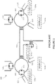
- FIG. 1 is a schematic diagram of a portion of an exemplary superconducting quantum processor 100 designed for AQC (and/or quantum annealing) that may be adapted for use in accordance with the present systems and methods.
- the portion of superconducting quantum processor 100 shown in Figure 1 includes two superconducting qubits 101, 102 and a tunable ZZ- coupler 111 coupling (i.e., a diagonal coupler) information therebetween (i.e., providing pair-wise coupling between qubits 101 and 102). While the portion of quantum processor 100 shown in Figure 1 includes only two qubits 101, 102 and one coupler 111, those of skill in the art will appreciate that quantum processor 100 may include any number of qubits and any number of coupling devices coupling information therebetween.
- Quantum processor 100 may be implemented to physically realize AQC and/or QA by initializing the system with the Hamiltonian described by Equation 2 and evolving the system to the Hamiltonian described by Equation 3 in accordance with the evolution described by Equation 1.
- Quantum processor 100 includes a plurality of interfaces 121-125 that are used to configure and control the state of quantum processor 100.
- Each of interfaces 121-125 may be realized by a respective inductive coupling structure, as illustrated, as part of a programming subsystem and/or an evolution subsystem.
- Such a programming subsystem and/or evolution subsystem may be separate from quantum processor 100, or it may be included locally (i.e., on-chip with quantum processor 100) as described in, for example, US Patent 7,876,248 and US Patent 8,035,540 .
- interfaces 121 and 124 may each be used to couple a flux signal into a respective compound Josephson junction 131,132 of qubits 101 and 102, thereby realizing the ⁇ i terms in the system Hamiltonian.
- This coupling provides the off-diagonal ⁇ x terms of the Hamiltonian described by Equation 2 and these flux signals are examples of "disordering signals.”
- interfaces 122 and 123 may each be used to couple a flux signal into a respective qubit loop of qubits 101 and 102, thereby realizing the h i terms in the system Hamiltonian.
- This coupling provides the diagonal ⁇ z terms of Equation 3.
- interface 125 may be used to couple a flux signal into coupler 111, thereby realizing the J ij term(s) in the system Hamiltonian.
- This coupling provides the diagonal ⁇ z i ⁇ z i terms of Equation 3.
- the contribution of each of interfaces 121-125 to the system Hamiltonian is indicated in boxes 121a-125a, respectively.
- the terms "problem formulation" and "configuration of a number of programmable parameters" are used to refer to, for example, a specific assignment of h i and J ij terms in the system Hamiltonian of a superconducting quantum processor via, for example, interfaces 121-125.
- the term "programming subsystem” is used to generally describe the interfaces (e.g., “programming interfaces” 122, 123, and 125) used to apply the programmable parameters (e.g., the h i and J ij terms) to the programmable elements of quantum processor 100 and other associated control circuitry and/or instructions.
- the programming interfaces of the programming subsystem may communicate with other subsystems which may be separate from the quantum processor or may be included locally on the processor.
- the term "evolution subsystem” is used to generally describe the interfaces (e.g., “evolution interfaces” 121 and 124) used to evolve the programmable elements of quantum processor 100 and other associated control circuitry and/or instructions.
- the evolution subsystem may include annealing signal lines and their corresponding interfaces (121, 124) to the qubits (101, 102).
- Quantum processor 100 also includes readout devices 141 and 142, where readout device 141 is configured to read out the state of qubit 101 and readout device 142 is configured to read out the state of qubit 102.
- each of readout devices 141 and 142 comprises a respective DC-SQUID that is configured to inductively couple to the corresponding qubit (qubits 101 and 102, respectively).
- the term "readout subsystem" is used to generally describe the readout devices 141, 142 used to read out the final states of the qubits (e.g., qubits 101 and 102) in the quantum processor to produce a bit string.
- the readout subsystem may also include other elements, such as routing circuitry (e.g., latching elements, a shift register, or a multiplexer circuit) and/or may be arranged in alternative configurations (e.g., an XY-addressable array, an XYZ-addressable array, etc.). Qubit readout may also be performed using alternative circuits, such as that described in PCT Patent Application Publication WO 2012-064974 .
- routing circuitry e.g., latching elements, a shift register, or a multiplexer circuit
- alternative configurations e.g., an XY-addressable array, an XYZ-addressable array, etc.
- Qubit readout may also be performed using alternative circuits, such as that described in PCT Patent Application Publication WO 2012-064974 .
- a quantum processor may employ any number of qubits, couplers, and/or readout devices, including a larger number (e.g., hundreds, thousands or more) of qubits, couplers and/or readout devices.
- a quantum processor e.g., processor 100
- processors may employ any number of qubits, couplers, and/or readout devices, including a larger number (e.g., hundreds, thousands or more) of qubits, couplers and/or readout devices.
- the application of the teachings herein to processors with a different (e.g., larger) number of computational components should be readily apparent to those of ordinary skill in the art.
- At least some of the devices illustrated in Figure 1 are simplified in order to enhance clarity.
- the structure of the qubits (101, 102) and the interface to the readout devices (141, 142) are simplified in Figure 1 in order to reduce clutter.
- the simplified circuits of quantum processor 100 may be sufficient for some applications, a quantum processor may employ qubit circuits and/or readout schemes that are considerably more complicated than those which are illustrated in Figure 1 .
- Adiabatic quantum computing algorithms and quantum annealing algorithms are generally understood in the art to enjoy some robustness against the effects of decoherence and noise, at least when compared to gate/circuit model quantum computing algorithms.
- decoherence and noise effects may still influence the operation of a quantum processor implementing adiabatic/annealing algorithms.
- decoherence and noise effects may cause the actual parameters realized in the problem Hamiltonian (i.e., Equation 3) to diverge from the parameters intended to be programmed via programming interfaces 121-125 such that the quantum processor may ultimately "solve" a problem that is different from the target problem that the quantum processor was programmed to solve.
- the present systems and methods provide schemes for correcting such unwanted errors.
- Some error-correcting codes for adiabatic quantum computation have been proposed in the art, but these proposals typically require higher-order interactions between qubits and multiple X, Y, and Z interactions between qubits (e.g., 4-local and 6-local X, Y, and Z Hamiltonians as opposed to the 2-local Z Hamiltonian of Equation 3 that is realizable by the pair-wise ZZ-coupling in processor 100) and/or high bandwidth control to enable precise gate application.
- the present systems and methods provide error correction schemes that may be implemented using low bandwidth control and easier-to-implement 2-local Z Hamiltonians such as Equation 3.
- a quantum processor designed to perform adiabatic and/or annealing algorithms may be adapted to implement a replica coding scheme in order to reduce the effects of decoherence and noise.
- the problem Hamiltonian e.g., Equation 3
- the problem Hamiltonian may be adapted, for example, by encoding multiple identical instances (or "replicas") of the problem within the quantum processor architecture.
- Figure 2 is an illustrative diagram showing an exemplary plurality of instances 200 of replica coding in accordance with the present systems and methods.
- nodes 201 represent qubits (only one called out in the Figure to reduce clutter)
- lines 211 represent coupling devices (only one called out in the Figure to reduce clutter)
- circles 221, 222 represent problem instances.
- Instance 221 represents a first instance of a problem programmed into a quantum processor, such as an instance of Equation 3 programmed into quantum processor 100 (with processor 100 being extended to include at least ten qubits and at least fifteen couplers).
- the effects of decoherence and noise on the solution of problem instance 221 may be reduced by simultaneously programming a second instance 222 into a separate set of qubits and couplers in the quantum processor and coupling at least some of the qubits of the second instance 222 to the first instance 221.
- second instance 222 is a copy or "replica" of first instance 221.
- the coupling between replicas provides a mechanism for correcting or stabilizing any errors or anomalies that may appear in any specific qubit 201 or instance 221, 222 by effectively smearing out the influence of noise. For example, if a form of noise has an influence of X on a qubit in instance 221, then that same form of noise may have an influence of about X /2 on the same qubit in instance 221 when that qubit is coupled to a replica qubit in instance 222.
- the influence of decoherence/noise may be inversely proportional to the number of replica instances in the quantum processor such that the influence of decoherence/noise may decrease as the number of replica instances increases.
- Figure 2 depicts two instances 221, 222 of a problem, any number of instances (i.e., any number of replicas, such as 2 replicas, 5 replicas, 10 replicas, 20 replicas, 100 replicas, etc.) may be employed provided there are sufficient qubits in the quantum processor to encode each instance.
- the coupling between replicas/instances is weaker than the coupling between qubits of the same instance (e.g., the coupling between qubits within instance 221).
- the coupling between qubits of instance 221 with qubits of replicas is fewer than the number of qubits in qubits of instance 221.
- the coupling between qubits of instance 221 with qubits of replicas is equal to the number of qubits in qubits of instance 221.
- the coupling between qubits of instance 221 with qubits of replicas is a diagonal coupling.
- replica qubits may be programmed slightly differently from one another (and/or some pairs of replica qubits may be coupled together slightly differently from other pairs of replica qubits) in order to realize specific error correction codes, such as for example, a majority voting scheme.
- the strength of the coupling between problem instances and replicas is weak compared to the coupling between qubits of the same instance.
- the strength of a coupling is measured, represented or determined by the energy of the coupling relative to a characteristic energy of the problem programmed into the quantum processor.
- the characteristic energy of the problem programmed into the quantum processor can be the maximum coupling value, the maximum bias value, or a combination of the two.
- a weaker coupling is smaller than the characteristic energy.
- a strong coupling is one greater than the characteristic energy.
- a weak coupling is greater than noise in the problem programmed into the quantum processor while operating the quantum processor, if any. In some implementations, this noise is a fraction of the characteristic energy.
- the noise is 1/1000 of the characteristic energy. In others, the noise is about 1/100 of the characteristic energy. In other implementations, the noise is about a 1/20 of the characteristic energy. In still other implementations, the noise is about a 1/5 of the characteristic energy.
- the coupling between problem instances and replicas is weak but about and greater than the noise. In some implementations, the coupling between problem instances and replicas is weak but equal to and greater than the noise. In some implementations the coupling strength as a ratio of the characteristic energy is within a range. Example ranges include: 1/100,000 to 1/2; 1/100 to 1/10; and 1/25 to 1/15.
- replica coding schemes may be implemented in existing adiabatic quantum computing processors and/or quantum annealing processors provided a sufficient architecture of qubits and coupling devices exists to encode the problem instance and at least one (but potentially many more than one) replica instance.
- a quantum processor architecture may also be specifically adapted to facilitate replica coding.
- a quantum processor architecture may be specifically adapted to implement replica coding by physically arranging replica qubits sets in the quantum processor architecture.
- a first set of qubits and coupling devices may be arranged on a first layer of a quantum processor
- a first set of replica qubits and replica coupling devices may be arranged on a second layer of the quantum processor with at least some qubits in the first set of replica qubits communicatively coupleable (e.g., weakly communicatively coupleable via coupling devices) to corresponding qubits in the first set of qubits
- a second set of replica qubits and replica coupling devices may be arranged on a third layer of the quantum processor with at least some qubits in the second set of replica qubits communicatively coupleable (e.g., weakly communicatively coupleable via coupling devices) to corresponding qubits in either the first set of qubits, the first set of replica qubits, or both the first set of qubits and the first set of replica qubits
- FIG 3 is a schematic diagram of a portion of an exemplary quantum processor architecture 300 adapted to facilitate replica coding in accordance with the present systems and methods.
- Quantum processor 300 includes qubits 301 (illustrated as solid black nodes, only one called out to reduce clutter) and coupling devices 311 (illustrated as solid black lines, only one called out to reduce clutter).
- Quantum processor 300 is illustratively divided into four quadrants, with each quadrant representing a specific set of qubits 301 and coupling devices 311 (i.e., a specific instance as described previously).
- instance 321 includes sixteen qubits 301 and twenty-four couplers 311.
- Each qubit 301 in instance 321 is coupled to a first corresponding replica qubit in instance 322 and a second corresponding replica qubit in instance 323; each qubit in instance 322 is coupled to a first corresponding replica qubit in instance 321 and a second corresponding replica qubit in instance 324; each qubit in instance 323 is coupled to a first corresponding replica qubit in instance 321 and a second corresponding replica qubit in instance 324; and each qubit in instance 324 is coupled to a first corresponding replica qubit in instance 322 and a second corresponding replica qubit in instance 323.
- each of instances 321-324 are nominally identical to one another.
- Inter-instance couplings are provided by coupling devices 331, which are represented by dashed lines in Figure 3 (only one called out to reduce clutter).
- Inter-instance coupling devices 331 may be substantially similar to intra-instance coupling devices 311; however, inter-instance coupling may not need to provide the same range of tenability or strength of coupling as intra-instance coupling and, accordingly, intra-instance coupling devices 331 may be simplified to provide weaker and less tunable coupling than intra-instance coupling devices 311.
- Inter-instance coupling devices 331 may be simplified in comparison to intra-instance coupling devices 311. Similarly, some replicas/instances (e.g., at least one of instances 321, 322, 323, 324) may not include read out devices. In some algorithms, it may be necessary to read out from only one instance and not from any replicas. In other algorithms, it may be advantageous to read out form multiple instances, in which case read out devices may be required in multiple or all instances/replicas. Some instances may share read out devices and/or some instances may share at least some programming circuitry.
- Figure 4 shows an exemplary method 400 of implementing replica coding in adiabatic quantum computation and/or quantum annealing, in accordance with the present systems and methods.
- An application of the method 400 is determining a suitable coupling strength between instances. For example, determining a suitable coupling strength between a problem instance and a replica. Not all portions of the method 400 need to be performed. The order of the portions of method 400 shown is exemplary and other orders are possible. Operation and acts with the method 400 are performed by a replica coder or another device for the replica coder.
- a replica coder receives a noise profile for a quantum processor at 402.
- the replica coder receives a problem formulation.
- the problem formulation may, for example, take the form of an optimization problem defined on a graph.
- the replica coder embeds or causes the embedding of the problem formulation onto the quantum processor.
- the embedding causes a first plurality of qubits to be logically associated with or to represent or otherwise be assigned to the problem formulation.
- the replica coder embeds or causes the embedding of one or more replicas of the problem formulation onto the quantum processor.
- the embedding causes a second plurality of qubits to be logically associated with or represent or otherwise be assigned to the first replica of the problem formulation.
- Further replicas may be present, with respective pluralities of qubits logically associated therewith, representing or assigned to the respective replicas.
- the replica coder sets the couplings and the coupling strength between the first plurality of qubits which are logically associated with or represent the problem formulation and sets the couplings and the coupling strengths of the second plurality of qubits logically associated with or which represent the first replica of the problem formulation.
- the replica coder may set the coupling and coupling strength of respective pluralities of qubits.
- the setting of the couplings and cooling strengths 408 may be an iterative operation.
- the quantum processor is evolved by quantum annealing.
- the results are read out. For example, a first set of results may be generated by reading out from the first plurality of qubits, and a second set of results from reading out the second plurality of qubits.
- the reading out 412 may in some implementations be an iterative operation.
- the method 400 is potentially iterative with testing 414 and resultant.
- the replica coder tests for agreement between the first set of results and the second set of results. If there is more than one replica, testing for agreement is performed between all result sets. In some unclaimed embodiments, agreement occurs or is found or determined to exist where a qubit and its corresponding replica have the same final value. If agreement is found, the replica coder returns the plurality of couplings between the first plurality of qubits associated with the problem formulation, and the second plurality of qubits associated with replica at 416. If agreement is not found, control returns to 408 where the replica coder iterates through the setting 408, evolving 410, reading out 412, and testing 414.
- the couplings are set at a bottom end of a range and increased with lack of agreement (i.e., disagreement). In some unclaimed embodiments, the couplings are set at a top end of a range and decreased with agreement. The branching in response to the testing 414 is reversed in such a case.
- Figure 5 shows an exemplary method 500 of implementing replica coding in adiabatic quantum computation and/or quantum annealing, in accordance with the present systems and methods.
- An application of the method 500 includes using one or more replicas to guard against errors in adiabatic quantum computing and/or quantum annealing.
- the order of the portions of method 500 shown is exemplary and other orders are possible. Operation and acts with the method 500 are performed by a replica coder or another device for the replica coder.
- the replica coder receives a problem formulation.
- the replica coder may receive an optimization problem defined on a graph.
- the problem formulation is embedded onto a quantum processor.
- a first plurality of qubits may be logically associated with, configured to represent or otherwise assigned to the problem formulation.
- the replica coder embeds one or more replicas of the problem formulation onto the quantum processor.
- a second plurality of qubits may be logically associated with, configured to represent or otherwise assigned to the first replica of the problem formulation.
- Further replicas may be present and embedded at 504.
- the replica coder sets the couplings between the first plurality of qubits, the second plurality of qubits, and optionally further plurality of qubits if additional replicas are present.
- the quantum processor is evolved by quantum annealing.
- the replica coder has ideally set the couplings between the problem formulation and its replica(s) such that correct result is obtained. Methods of finding the correct couplings is described above. A correct solution to many problems is easy to verify, for example, in factoring finding the factors is hard verifying them is simple.
- a read out is made of the first plurality of qubits associated with the problem formulation, and a read out is made of the second plurality of qubits associated with the replica.
- one of the plurality of qubits associated with the problem formulation or the replicas present is read out.
- two or more of the plurality of qubits associated with the problem formulation or the replicas is read out. Where multiple results are present, the results can be compared and used to detect errors. In the case of three or more results, errors can be corrected, for example, by majority voting.
- the results from read out are returned, whether those results are correct or not.
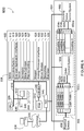
- FIG. 6 is a functional block diagram showing a computing system 600 employing at least one quantum processor in accordance with the present systems and methods.
- FIG. 6 and the following discussion provide a brief and general description of a suitable computing environment in which various embodiments of an analog computer including a quantum processor.
- embodiments will be described in the general context of computer-executable instructions, such as program application modules, objects or macros being executed by a computer.
- PCs personal computers
- network PCs mini-computers
- mainframe computers mainframe computers
- the embodiments can be practiced in distributed computing environments where tasks or modules are performed by remote processing devices, which are linked through a communications network.
- program modules may be located in both local and remote memory storage devices.
- Figure 6 shows a computing system 600 operable to solve problems, according to one illustrated embodiment.
- the computing system 600 includes a digital computing subsystem 602 and an analog computing subsystem 604 communicatively coupled to the digital computing subsystem 602.
- the digital computing subsystem 602 includes one or more processing units 606, system memory 608, and system bus 610 that couple various system components including the system memory 608 to the processing unit 606.
- the digital computing subsystem 602 will at times be referred to in the singular herein, but this is not intended to limit the application to a single digital computing subsystem 602 since in typical embodiments, there will be more than one digital computing subsystem 602 or other device involved. Other computing systems may be employed, such as conventional and personal computers, where the size or scale of the system allows.
- the processing unit 606 may be any logic processing unit, such as one or more central processing units (“CPUs”), digital signal processors ("DSPs”), application-specific integrated circuits ("ASICs”), etc. Unless described otherwise, the construction and operation of the various blocks shown in Figure 6 are of conventional design. As a result, such blocks need not be described in further detail herein, as they will be understood by those skilled in the relevant art.
- the system bus 610 can employ any known bus structures or architectures, including a memory bus with memory controller, a peripheral bus, and a local bus.
- the system memory 608 may include read-only memory (“ROM”) and random access memory (“RAM”).
- ROM read-only memory
- RAM random access memory
- a basic input/output system (“BIOS”) 612 which can form part of the ROM, contains basic routines that help transfer information between elements within the digital computing subsystem 602, such as during startup.
- the digital computing subsystem 602 also includes non-volatile memory 614.
- the non-volatile memory 614 may take a variety of forms, for example a hard disk drive for reading from and writing to a hard disk, and an optical disk drive and a magnetic disk drive for reading from and writing to removable optical disks and magnetic disks, respectively.
- the optical disk can be read by a CD-ROM, while the magnetic disk can be a magnetic floppy disk or diskette.
- the hard disk drive, optical disk drive and magnetic disk drive communicate with the processing unit 606 via the system bus 610.
- the hard disk drive, optical disk drive and magnetic disk drive may include appropriate interfaces or controllers 616 coupled between such drives and the system bus 610, as is known by those skilled in the relevant art.
- the drives, and their associated computer-readable media provide non-volatile storage of computer readable instructions, data structures, program modules and other data for the digital computing subsystem 602.
- the depicted digital computing subsystem 602 has been described as employing hard disks, optical disks and/or magnetic disks, those skilled in the relevant art will appreciate that other types of non-volatile computer-readable media that can store data accessible by a computer may be employed, such a magnetic cassettes, flash memory cards, digital video disks ("DVD”), Bernoulli cartridges, RAMs, ROMs, smart cards, etc.
- system memory 608 may store an operating system 618, end user application interfaces 620, server applications 622, scheduler modules 624, and/or meta-optimizer modules 626.
- system memory 608 may store a replica coding module 627 for implementing methods of Figures 1-5 .
- system memory 608 may additionally or alternatively store one or more mapper modules 628, analog processor interface modules 630, and/or driver modules 632. The operation and function of these modules are discussed in detail below.
- the system memory 608 may also include one or more networking applications 634, for example a Web server application and/or Web client or browser application for permitting the digital computing subsystem 602 to exchange data with sources via the internet, corporate intranets, or other networks as described below, as well as with other server applications on server computers such as those further discussed below.
- the networking application 634 in the depicted embodiment is markup language based, such as hypertext markup language (“HTML”), extensible markup language (“XML”) or wireless markup language (“WML”), and operates with markup languages that use syntactically delimited characters added to the data of a document to represent the structure of the document.
- HTML hypertext markup language
- XML extensible markup language
- WML wireless markup language
- a number of Web server applications and Web client or browser applications are commercially available such those available from Mozilla and Microsoft.
- the operating system 618 and various applications 620, 622, 624, 626, 628, 630, 632, 634 and/or data can be stored on the hard disk of the hard disk drive, the optical disk of the optical disk drive and/or the magnetic disk of the magnetic disk drive.
- the digital computing subsystem 602 can operate in a networked environment using logical connections to one or more end user computing systems 636 (only one shown), such as one or more remote computers or networks.
- the digital computing subsystem 602 may be logically connected to one or more end user computing systems 636 under any known method of permitting computers to communicate, for example through a network 638 such as a local area network ("LAN”) and/or a wide area network (“WAN”) including, for example, the Internet.
- LAN local area network
- WAN wide area network
- Such networking environments are well known including wired and wireless enterprise-wide computer networks, intranets, extranets, and the Internet.
- Other embodiments include other types of communication networks such as telecommunications networks, cellular networks, paging networks, and other mobile networks.
- the information sent or received via the communications channel may, or may not be encrypted.
- the digital computing subsystem 602 When used in a LAN networking environment, the digital computing subsystem 602 is connected to the LAN through an adapter or network interface card 640 (communicative linked to the system bus 610). When used in a WAN networking environment, the digital computing subsystem 602 may include an interface and modem (not shown) or other device, such as the network interface card 640, for establishing communications over the WAN/Internet.
- program modules, application programs, or data, or portions thereof can be stored in the digital computing subsystem 602 for provision to the networked computers.
- the digital computing subsystem 602 is communicatively linked through the network 638 with TCP/IP middle layer network protocols; however, other similar network protocol layers are used in other embodiments, such as user datagram protocol ("UDP").
- UDP user datagram protocol
- an operator can enter commands and information into the digital computing subsystem 602 through the end user application interface 648 including input devices, such as a keyboard 644, and a pointing device, such as a mouse 646.
- Other input devices can include a microphone, joystick, scanner, etc.
- These and other input devices are connected to the processing unit 606 through the end user application interface 620, such as a serial port interface that couples to the system bus 610, although other interfaces, such as a parallel port, a game port, or a wireless interface, or a universal serial bus (“USB”) can be used.
- a monitor 642 or other display device is coupled to the bus 610 via a video interface, such as a video adapter (not shown).
- the digital computing subsystem 602 can include other output devices, such as speakers, printers, etc.
- the analog computing subsystem 604 includes an analog processor, for example, a quantum processor 650.
- the quantum processor 650 includes multiple qubit nodes 652a, b, c, and so on to n (collectively 652) and multiple coupling devices 654a, b, c, and so on to m [[-]](collectively 654).
- the analog computing subsystem 604 includes a readout device 656 for reading out one or more qubit nodes 652.
- readout device 656 may include multiple dc-SQUID magnetometers, with each dc-SQUID magnetometer being inductively connected to a qubit node 652 and NIC 640 receiving a voltage or current from readout device 656.
- the dc-SQUID magnetometers comprise a loop of superconducting material interrupted by two Josephson junctions and are well known in the art.
- the analog computing subsystem 604 also includes a qubit control system 658 including controller(s) for controlling or setting one or more parameters of some or all of the qubit nodes 652.
- the analog computing subsystem 604 further includes a coupling device control system 660 including coupling controller(s) for coupling devices 654.
- each coupling controller in coupling device control system 660 may be capable of tuning the coupling strength of a coupling device 654between a minimum and a maximum value.
- Coupling devices 654 may be tunable to provide ferromagnetic or anti-ferromagnetic coupling between qubit nodes 652.
- NIC 640 may include appropriate hardware required for interfacing with qubit nodes 652 and coupling devices 654, either directly or through readout device 656, qubit control system 658, and/or coupling device control system 660.
- NIC 640 may include software and/or hardware that translate commands from driver module 632 into signals (e.g., voltages, currents, optical signals, etc.) that are directly applied to qubit nodes 652 and coupling devices 554.
- NIC 640 may include software and/or hardware that translates signals (representing a solution to a problem or some other form of feedback) from qubit nodes 652 and coupling devices 654.
- analog processor interface module 630 may communicate with driver module 632 rather than directly with NIC 640 in order to send and receive signals from quantum processor 650.
- NIC 640 can be divided into two classes of functionality: data acquisition and control. Different types of chips may be used to handle each of these discrete functional classes. Data acquisition is used to measure the physical properties of qubit nodes 652 after quantum processor 650 has completed a computation. Such data can be measured using any number of customized or commercially available data acquisition microcontrollers including, but not limited to, data acquisition cards manufactured by Elan Digital Systems (Fareham, UK) including the AD132, AD136, MF232, MF236, AD142, AD218 and CF241 cards. Alternatively, data acquisition and control may be handled by a single type of microprocessor, such as the Elan D403C or D480C. There may be multiple NICs 640 in order to provide sufficient control over qubit nodes 652 and coupling devices 654 and in order to measure the results of a computation conducted on quantum processor 650.
- Data acquisition is used to measure the physical properties of qubit nodes 652 after quantum processor 650 has completed a computation. Such data can be measured using any number of customized or
- Coupling devices 654 may either couple qubits 652 together ferromagnetically or anti-ferromagnetically or not couple qubits 652 together.
- a ferromagnetic coupling between two qubits 652 drives the qubits 652 to have the same state, whereas an anti-ferromagnetic coupling drives the qubits 652 to have opposite states.
- Charge-based coupling devices 654 may also be used. More information on coupling devices 654 useful in the present systems, methods and articles can be found in U.S. patent application Ser. No. 11/247,857 (now US patent 7,619,437 ).
- the analog computing subsystem 604 may be a superconducting quantum computer, examples of which include qubit registers, readout devices and ancillary devices.
- Superconducting quantum computers normally are operated at milliKelvin temperatures and often are operated in a dilution refrigerator.
- An example of a dilution refrigerator is the Leiden Cryogenics B.V. MNK 126 series (Galgewater No. 21, 2311 VZ Leiden, The Netherlands). All or part of the components of the analog computing subsystem 604 may be housed in the dilution refrigerator.
- qubit control system 658 and coupling device control system 660 may be housed outside the dilution refrigerator with the quantum processor 650 being housed inside the dilution refrigerator.
- Superconducting qubits useful in the present systems, methods and articles include superconducting flux qubits and superconducting charge qubits, both described in Makhlin et al., 2001, Reviews of Modern Physics 73, pp. 357-400 .
- flux qubits that can be used include rf-SQUIDs, which have a superconducting loop interrupted by a Josephson junction, and persistent current qubits, which have a superconducting loop interrupted by three Josephson junctions. See Mooij et al., 1999, Science 285, 1036 ; and Orlando et al., 1999, Physical Review B 60, 15398 .
- Superconducting coupling devices useful in the present systems, methods and articles include rf-SQUIDs and dc-SQUIDs, which couple qubits together by flux.
- SQUIDs have a superconducting loop interrupted by one (an rf-SQUID) or two (a dc-SQUID) Josephson junctions.
- the coupling devices used may be capable of both ferromagnetic and anti-ferromagnetic coupling.
- the readout devices 656, may also be superconducting devices, such as a dc-SQUID, or instead, a tank circuit may be used for the readout devices 656.
- the readout devices 656 may read out the state of a qubit 652 in the flux regime, or alternatively, read out the state of the qubit in the charge regime.
- Charge-based readout devices and charged-based local bias devices may be used.
- An exemplary system is provided in Figure 3 .
- An exemplary method is illustrated in Figure 2 , where a problem instance in programmatically mapped to (e.g., encoded or embedded in) a first set of qubits, the same problem instance in programmatically mapped to (e.g., encoded or embedded in) a second set of qubits, and coupling is provided between at least some qubits in the first set of qubits and at least some qubits in the second set of qubits.
Landscapes
- Engineering & Computer Science (AREA)
- Theoretical Computer Science (AREA)
- Physics & Mathematics (AREA)
- General Physics & Mathematics (AREA)
- General Engineering & Computer Science (AREA)
- Quality & Reliability (AREA)
- Condensed Matter Physics & Semiconductors (AREA)
- Computational Mathematics (AREA)
- Artificial Intelligence (AREA)
- Data Mining & Analysis (AREA)
- Evolutionary Computation (AREA)
- Mathematical Analysis (AREA)
- Mathematical Optimization (AREA)
- Pure & Applied Mathematics (AREA)
- Computing Systems (AREA)
- Mathematical Physics (AREA)
- Software Systems (AREA)
- Superconductor Devices And Manufacturing Methods Thereof (AREA)
Description
- The present systems and methods generally relate to error correction in quantum computation and particularly relate to error correction in implementations of adiabatic quantum computation and quantum annealing.
- Adiabatic quantum computation typically involves evolving a system from a known initial Hamiltonian (the Hamiltonian being an operator whose eigenvalues are the allowed energies of the system) to a final Hamiltonian by gradually changing the Hamiltonian. A simple example of an adiabatic evolution is given by:


- The evolution process in adiabatic quantum computing may sometimes be referred to as annealing. The rate that s changes, sometimes referred to as an evolution or annealing schedule, is normally slow enough that the system is always in the instantaneous ground state of the evolution Hamiltonian during the evolution, and transitions at anti-crossings (i.e., when the gap size is smallest) are avoided. Further details on adiabatic quantum computing systems, methods, and apparatus are described in, for example,
US Patent 7,135,701 andUS Patent 7,418,283 . - Quantum annealing is a computation method that may be used to find a low-energy state, typically preferably the ground state, of a system. Somewhat similar in concept to classical annealing, the method relies on the underlying principle that natural systems tend towards lower energy states because lower energy states are more stable. However, while classical annealing uses classical thermal fluctuations to guide a system to its global energy minimum, quantum annealing may use quantum effects, such as quantum tunneling, to reach a global energy minimum more accurately and/or more quickly than classical annealing. It is known that the solution to a hard problem, such as a combinatorial optimization problem, may be encoded in the ground state of a system Hamiltonian (e.g., the Hamiltonian of an Ising spin glass) and therefore quantum annealing may be used to find the solution to such a hard problem. Adiabatic quantum computation may be considered a special case of quantum annealing for which the system, ideally, begins and remains in its ground state throughout an adiabatic evolution. Thus, those of skill in the art will appreciate that quantum annealing systems and methods may generally be implemented on an adiabatic quantum computer, and vice versa. Throughout this specification and the appended claims, any reference to quantum annealing is intended to encompass adiabatic quantum computation unless the context requires otherwise.
- Quantum annealing uses quantum mechanics as a source of disorder during the annealing process. The optimization problem is encoded in a Hamiltonian HP , and the algorithm introduces strong quantum fluctuations by adding a disordering Hamiltonian HD that does not commute with HP. An example case is:

- The gradual reduction of Γ in quantum annealing may follow a defined schedule known as an annealing schedule. Unlike traditional forms of adiabatic quantum computation where the system begins and remains in its ground state throughout the evolution, in quantum annealing the system may not remain in its ground state throughout the entire annealing schedule. As such, quantum annealing may be implemented as a heuristic technique, where low-energy states with energy near that of the ground state may provide approximate solutions to the problem.
- A quantum processor may take the form of a superconducting quantum processor. A superconducting quantum processor may include a number of qubits and associated local bias devices, for instance two or more superconducting qubits. A superconducting quantum processor may also employ coupling devices (i.e., "couplers") providing communicative coupling between qubits. Further details and embodiments of exemplary quantum processors that may be used in conjunction with the present systems and methods are described in, for example,
US Patent 7,533,068 ,US Patent 8,008,942 ,US Patent Publication 2008-0176750 (nowUS Patent 8,195,596 ),US Patent Publication 2009-0121215 (nowUS Patent 8,190,548 ), andUS Patent Publication 201 1 -0022820 (nowUS Patent 8,421 ,053 ). - Document "Theory of Quantum Annealing of an Ising Spin Glass" (G. E. Santoro, et. al), relates to the theory of quantum annealing of an Ising glass, and includes a comparison of the effectiveness of quantum annealing versus classical annealing.
- Document "Optimization by Quantum Annealing: Lessons from hard 3-SAT cases" (D. A. Battaglia, et.al) refers to a comparison of the performance of Path-Integral Monte Carlo Quantum Annealing strategies against a standard thermal simulated annealing on a very hard instance of a classical NP-complete problem, 3-SAT.
- Patent publication
US 8,234,103 B2 discloses devices, methods and articles that allow communications between qubits to provide an architecture for universal adiabatic quantum computation. The architecture includes a first coupled basis A1B1 and a second coupled basis A2B2 that does not commute with the first basis A1B1. - The present invention is defined in the independent claims. Particular embodiments are set out in the respective dependent claims.
- A quantum processor may be summarized as including a first set of qubits and a first set of coupling devices providing communicative coupling between qubits in the first set of qubits; a first set of replica qubits and a first set of replica coupling devices providing communicative coupling between the first set of replica qubits, wherein for each qubit in the first set of qubits a corresponding replica qubit exists in the first set of replica qubits, and for each coupling device in the first set of coupling devices a replica coupling device exists in the first set of replica coupling devices; and a second set of coupling devices, wherein each coupling device in the second set of coupling devices provides communicative coupling between a qubit in the first set of qubits and the corresponding replica qubit in the first set of replica qubits. The quantum processor may include a superconducting quantum processor, the qubits may include superconducting qubits, and the coupling devices may include superconducting coupling devices.
- In the drawings, identical reference numbers identify similar elements or acts. The sizes and relative positions of elements in the drawings are not necessarily drawn to scale. For example, the shapes of various elements and angles are not drawn to scale, and some of these elements are arbitrarily enlarged and positioned to improve drawing legibility. Further, the particular shapes of the elements as drawn are not intended to convey any information regarding the actual shape of the particular elements, and have been solely selected for ease of recognition in the drawings.
-
Figure 1 is a schematic diagram of a portion of an exemplary superconducting quantum processor designed for adiabatic quantum computation (and/or quantum annealing) that may be adapted for use in accordance with the present systems and methods. -
Figure 2 is an illustrative diagram showing an exemplary plurality of instances of replica coding in accordance with the present systems and methods. -
Figure 3 is a schematic diagram of a portion of an exemplary quantum processor architecture adapted to facilitate replica coding in accordance with the present systems and methods. -
Figures 4 and5 are illustrative flow diagrams showing exemplary methods of implementing replica coding in adiabatic quantum computation (and/or quantum annealing) in accordance with the present systems and methods. -
Figure 6 is a functional block diagram showing a computing system employing at least one quantum processor in accordance with the present systems and methods. - In the following description, some specific details are included to provide a thorough understanding of various disclosed embodiments. One skilled in the relevant art, however, will recognize that embodiments may be practiced without one or more of these specific details, or with other methods, components, materials, etc. In other instances, well-known structures associated with quantum processors, such as quantum devices, coupling devices, and control systems including microprocessors, drive circuitry and nontransitory computer- or processor-readable media such as nonvolatile memory for instance read only memory (ROM), electronically erasable programmable ROM (EEPROM) or FLASH memory, etc., or volatile memory for instance static or dynamic random access memory (ROM) have not been shown or described in detail to avoid unnecessarily obscuring descriptions of the embodiments of the present systems and methods. Throughout this specification and the appended claims, the words "element" and "elements" are used to encompass, but are not limited to, all such structures, systems and devices associated with quantum processors, as well as their related programmable parameters.
- Unless the context requires otherwise, throughout the specification and claims which follow, the word "comprise" and variations thereof, such as, "comprises" and "comprising" are to be construed in an open, inclusive sense, that is as "including, but not limited to."
- Reference throughout this specification to "one embodiment," or "an embodiment," or "another embodiment" means that a particular referent feature, structure, or characteristic described in connection with the embodiment is included in at least one embodiment. Thus, the appearances of the phrases "in one embodiment," or "in an embodiment," or "another embodiment" in various places throughout this specification are not necessarily all referring to the same embodiment. Furthermore, the particular features, structures, or characteristics may be combined in any suitable manner in one or more embodiments.
- It should be noted that, as used in this specification and the appended claims, the singular forms "a," "an," and "the" include plural referents unless the content clearly dictates otherwise. Thus, for example, reference to a problem-solving system including "a quantum processor" includes a single quantum processor, or two or more quantum processors, including a grid or distributed network of multiple quantum processors. It should also be noted that the term "or" is generally employed in its sense including "and/or" unless the content clearly dictates otherwise.
- The headings provided herein are for convenience only and do not interpret the scope or meaning of the embodiments.
- The various embodiments described herein provide systems and methods for error correction in quantum computation. More specifically, the various embodiments described herein provide systems and methods for implementing error correction protocols in quantum processors designed to perform adiabatic quantum computation and/or quantum annealing algorithms.
- As an illustrative example, a superconducting quantum processor designed to perform adiabatic quantum computation and/or quantum annealing is used in the description that follows. However, a person of skill in the art will appreciate that the present systems and methods may be applied to any form of quantum processor hardware (e.g., superconducting, photonic, ion-trap, quantum dot, topological, etc.) implementing any form of quantum algorithm(s) (e.g., adiabatic quantum computation, quantum annealing, gate/circuit-based quantum computing, etc.).
- A typical adiabatic evolution may be represented by Equation 1:


Equations -
Figure 1 is a schematic diagram of a portion of an exemplary superconductingquantum processor 100 designed for AQC (and/or quantum annealing) that may be adapted for use in accordance with the present systems and methods. The portion of superconductingquantum processor 100 shown inFigure 1 includes twosuperconducting qubits coupler 111 coupling (i.e., a diagonal coupler) information therebetween (i.e., providing pair-wise coupling betweenqubits 101 and 102). While the portion ofquantum processor 100 shown inFigure 1 includes only twoqubits coupler 111, those of skill in the art will appreciate thatquantum processor 100 may include any number of qubits and any number of coupling devices coupling information therebetween. - The portion of
quantum processor 100 shown inFigure 1 may be implemented to physically realize AQC and/or QA by initializing the system with the Hamiltonian described byEquation 2 and evolving the system to the Hamiltonian described byEquation 3 in accordance with the evolution described byEquation 1.Quantum processor 100 includes a plurality of interfaces 121-125 that are used to configure and control the state ofquantum processor 100. Each of interfaces 121-125 may be realized by a respective inductive coupling structure, as illustrated, as part of a programming subsystem and/or an evolution subsystem. Such a programming subsystem and/or evolution subsystem may be separate fromquantum processor 100, or it may be included locally (i.e., on-chip with quantum processor 100) as described in, for example,US Patent 7,876,248 andUS Patent 8,035,540 . - In the operation of
quantum processor 100,interfaces qubits Equation 2 and these flux signals are examples of "disordering signals." Similarly, interfaces 122 and 123 may each be used to couple a flux signal into a respective qubit loop ofqubits Equation 3. Furthermore,interface 125 may be used to couple a flux signal intocoupler 111, thereby realizing the Jij term(s) in the system Hamiltonian. This coupling provides the diagonal σz iσz i terms ofEquation 3. InFigure 1 , the contribution of each of interfaces 121-125 to the system Hamiltonian is indicated in boxes 121a-125a, respectively. Thus, throughout this specification and the appended claims, the terms "problem formulation" and "configuration of a number of programmable parameters" are used to refer to, for example, a specific assignment of hi and Jij terms in the system Hamiltonian of a superconducting quantum processor via, for example, interfaces 121-125. - In the context of
quantum processor 100, the term "programming subsystem" is used to generally describe the interfaces (e.g., "programming interfaces" 122, 123, and 125) used to apply the programmable parameters (e.g., the hi and Jij terms) to the programmable elements ofquantum processor 100 and other associated control circuitry and/or instructions. As previously described, the programming interfaces of the programming subsystem may communicate with other subsystems which may be separate from the quantum processor or may be included locally on the processor. Similarly, in the context ofquantum processor 100, the term "evolution subsystem" is used to generally describe the interfaces (e.g., "evolution interfaces" 121 and 124) used to evolve the programmable elements ofquantum processor 100 and other associated control circuitry and/or instructions. For example, the evolution subsystem may include annealing signal lines and their corresponding interfaces (121, 124) to the qubits (101, 102). -
Quantum processor 100 also includesreadout devices readout device 141 is configured to read out the state ofqubit 101 andreadout device 142 is configured to read out the state ofqubit 102. In the embodiment shown inFigure 1 , each ofreadout devices qubits quantum processor 100, the term "readout subsystem" is used to generally describe thereadout devices qubits 101 and 102) in the quantum processor to produce a bit string. The readout subsystem may also include other elements, such as routing circuitry (e.g., latching elements, a shift register, or a multiplexer circuit) and/or may be arranged in alternative configurations (e.g., an XY-addressable array, an XYZ-addressable array, etc.). Qubit readout may also be performed using alternative circuits, such as that described in PCT Patent Application PublicationWO 2012-064974 - While
Figure 1 illustrates only twophysical qubits coupler 111, and tworeadout devices - At least some of the devices illustrated in
Figure 1 are simplified in order to enhance clarity. As an example, the structure of the qubits (101, 102) and the interface to the readout devices (141, 142) are simplified inFigure 1 in order to reduce clutter. While the simplified circuits ofquantum processor 100 may be sufficient for some applications, a quantum processor may employ qubit circuits and/or readout schemes that are considerably more complicated than those which are illustrated inFigure 1 . - Adiabatic quantum computing algorithms and quantum annealing algorithms are generally understood in the art to enjoy some robustness against the effects of decoherence and noise, at least when compared to gate/circuit model quantum computing algorithms. However, decoherence and noise effects may still influence the operation of a quantum processor implementing adiabatic/annealing algorithms. For example, decoherence and noise effects may cause the actual parameters realized in the problem Hamiltonian (i.e., Equation 3) to diverge from the parameters intended to be programmed via programming interfaces 121-125 such that the quantum processor may ultimately "solve" a problem that is different from the target problem that the quantum processor was programmed to solve. The present systems and methods provide schemes for correcting such unwanted errors.
- Some error-correcting codes for adiabatic quantum computation (e.g., Jordan et al., "Error-correcting codes for adiabatic quantum computation," Physical Review A, 74 052322 (2006)) have been proposed in the art, but these proposals typically require higher-order interactions between qubits and multiple X, Y, and Z interactions between qubits (e.g., 4-local and 6-local X, Y, and Z Hamiltonians as opposed to the 2-local Z Hamiltonian of
Equation 3 that is realizable by the pair-wise ZZ-coupling in processor 100) and/or high bandwidth control to enable precise gate application. The present systems and methods provide error correction schemes that may be implemented using low bandwidth control and easier-to-implement 2-local Z Hamiltonians such asEquation 3. - In accordance with the present systems and methods, a quantum processor designed to perform adiabatic and/or annealing algorithms (e.g.,
processor 100 fromFigure 1 ) may be adapted to implement a replica coding scheme in order to reduce the effects of decoherence and noise. As an example, the problem Hamiltonian (e.g., Equation 3) may be adapted to use linearly more qubits to achieve an exponential decrease in the effects of decoherence and noise. The problem Hamiltonian may be adapted, for example, by encoding multiple identical instances (or "replicas") of the problem within the quantum processor architecture. -
Figure 2 is an illustrative diagram showing an exemplary plurality ofinstances 200 of replica coding in accordance with the present systems and methods. InFigure 2 ,nodes 201 represent qubits (only one called out in the Figure to reduce clutter),lines 211 represent coupling devices (only one called out in the Figure to reduce clutter), and circles 221, 222 represent problem instances.Instance 221 represents a first instance of a problem programmed into a quantum processor, such as an instance ofEquation 3 programmed into quantum processor 100 (withprocessor 100 being extended to include at least ten qubits and at least fifteen couplers). In accordance with the present systems and methods, the effects of decoherence and noise on the solution ofproblem instance 221 may be reduced by simultaneously programming asecond instance 222 into a separate set of qubits and couplers in the quantum processor and coupling at least some of the qubits of thesecond instance 222 to thefirst instance 221. In this sense,second instance 222 is a copy or "replica" offirst instance 221. When the quantum processor is evolved, both thefirst instance 221 and thesecond instance 222 of the same problem are "solved" simultaneously and coupled together to effectively shrink the influence of decoherence and noise. The coupling between replicas (e.g., the coupling betweeninstances 221 and 222) provides a mechanism for correcting or stabilizing any errors or anomalies that may appear in anyspecific qubit 201 orinstance instance 221, then that same form of noise may have an influence of about X/2 on the same qubit ininstance 221 when that qubit is coupled to a replica qubit ininstance 222. In accordance with the present systems and methods, the influence of decoherence/noise may be inversely proportional to the number of replica instances in the quantum processor such that the influence of decoherence/noise may decrease as the number of replica instances increases. Thus, whileFigure 2 depicts twoinstances - The coupling between replicas/instances (e.g., the coupling between qubits of
instance 221 with qubits of instance 222) is weaker than the coupling between qubits of the same instance (e.g., the coupling between qubits within instance 221). In some implementations, the coupling between qubits ofinstance 221 with qubits of replicas is fewer than the number of qubits in qubits ofinstance 221. In some embodiments, the coupling between qubits ofinstance 221 with qubits of replicas is equal to the number of qubits in qubits ofinstance 221. In some embodiments, the coupling between qubits ofinstance 221 with qubits of replicas is a diagonal coupling. In some embodiments, replica qubits may be programmed slightly differently from one another (and/or some pairs of replica qubits may be coupled together slightly differently from other pairs of replica qubits) in order to realize specific error correction codes, such as for example, a majority voting scheme. - In some implementations, the strength of the coupling between problem instances and replicas is weak compared to the coupling between qubits of the same instance. In some implementations, the strength of a coupling is measured, represented or determined by the energy of the coupling relative to a characteristic energy of the problem programmed into the quantum processor. The characteristic energy of the problem programmed into the quantum processor can be the maximum coupling value, the maximum bias value, or a combination of the two. Thus, a weaker coupling is smaller than the characteristic energy. A strong coupling is one greater than the characteristic energy. In some implementations, a weak coupling is greater than noise in the problem programmed into the quantum processor while operating the quantum processor, if any. In some implementations, this noise is a fraction of the characteristic energy. In some embodiments, the noise is 1/1000 of the characteristic energy. In others, the noise is about 1/100 of the characteristic energy. In other implementations, the noise is about a 1/20 of the characteristic energy. In still other implementations, the noise is about a 1/5 of the characteristic energy.
- In some implementations, the coupling between problem instances and replicas is weak but about and greater than the noise. In some implementations, the coupling between problem instances and replicas is weak but equal to and greater than the noise. In some implementations the coupling strength as a ratio of the characteristic energy is within a range. Example ranges include: 1/100,000 to 1/2; 1/100 to 1/10; and 1/25 to 1/15.
- In accordance with the present systems and methods, replica coding schemes may be implemented in existing adiabatic quantum computing processors and/or quantum annealing processors provided a sufficient architecture of qubits and coupling devices exists to encode the problem instance and at least one (but potentially many more than one) replica instance. However, a quantum processor architecture may also be specifically adapted to facilitate replica coding.
- A quantum processor architecture may be specifically adapted to implement replica coding by physically arranging replica qubits sets in the quantum processor architecture. For example, a first set of qubits and coupling devices may be arranged on a first layer of a quantum processor, a first set of replica qubits and replica coupling devices may be arranged on a second layer of the quantum processor with at least some qubits in the first set of replica qubits communicatively coupleable (e.g., weakly communicatively coupleable via coupling devices) to corresponding qubits in the first set of qubits, a second set of replica qubits and replica coupling devices may be arranged on a third layer of the quantum processor with at least some qubits in the second set of replica qubits communicatively coupleable (e.g., weakly communicatively coupleable via coupling devices) to corresponding qubits in either the first set of qubits, the first set of replica qubits, or both the first set of qubits and the first set of replica qubits, and so on, for any number of sets of replica qubits and replica coupling devices. In some unclaimed embodiments, qubits from different replica sets may be included within the same physical layer of the quantum processor architecture.
-
Figure 3 is a schematic diagram of a portion of an exemplaryquantum processor architecture 300 adapted to facilitate replica coding in accordance with the present systems and methods.Quantum processor 300 includes qubits 301 (illustrated as solid black nodes, only one called out to reduce clutter) and coupling devices 311 (illustrated as solid black lines, only one called out to reduce clutter).Quantum processor 300 is illustratively divided into four quadrants, with each quadrant representing a specific set ofqubits 301 and coupling devices 311 (i.e., a specific instance as described previously). For example,instance 321 includes sixteenqubits 301 and twenty-fourcouplers 311. Eachqubit 301 ininstance 321 is coupled to a first corresponding replica qubit ininstance 322 and a second corresponding replica qubit ininstance 323; each qubit ininstance 322 is coupled to a first corresponding replica qubit ininstance 321 and a second corresponding replica qubit ininstance 324; each qubit ininstance 323 is coupled to a first corresponding replica qubit ininstance 321 and a second corresponding replica qubit ininstance 324; and each qubit ininstance 324 is coupled to a first corresponding replica qubit ininstance 322 and a second corresponding replica qubit ininstance 323. As will be understood form the above description, each of instances 321-324 are nominally identical to one another. Inter-instance couplings are provided bycoupling devices 331, which are represented by dashed lines inFigure 3 (only one called out to reduce clutter).Inter-instance coupling devices 331 may be substantially similar tointra-instance coupling devices 311; however, inter-instance coupling may not need to provide the same range of tenability or strength of coupling as intra-instance coupling and, accordingly,intra-instance coupling devices 331 may be simplified to provide weaker and less tunable coupling thanintra-instance coupling devices 311. -
Inter-instance coupling devices 331 may be simplified in comparison tointra-instance coupling devices 311. Similarly, some replicas/instances (e.g., at least one ofinstances -
Figure 4 shows anexemplary method 400 of implementing replica coding in adiabatic quantum computation and/or quantum annealing, in accordance with the present systems and methods. An application of themethod 400 is determining a suitable coupling strength between instances. For example, determining a suitable coupling strength between a problem instance and a replica. Not all portions of themethod 400 need to be performed. The order of the portions ofmethod 400 shown is exemplary and other orders are possible. Operation and acts with themethod 400 are performed by a replica coder or another device for the replica coder. - In some unclaimed embodiments, a replica coder receives a noise profile for a quantum processor at 402. At 404, the replica coder receives a problem formulation. The problem formulation may, for example, take the form of an optimization problem defined on a graph. At 406, the replica coder embeds or causes the embedding of the problem formulation onto the quantum processor. The embedding causes a first plurality of qubits to be logically associated with or to represent or otherwise be assigned to the problem formulation. Also at 406, the replica coder embeds or causes the embedding of one or more replicas of the problem formulation onto the quantum processor. The embedding causes a second plurality of qubits to be logically associated with or represent or otherwise be assigned to the first replica of the problem formulation. Further replicas may be present, with respective pluralities of qubits logically associated therewith, representing or assigned to the respective replicas.
- At 408, the replica coder sets the couplings and the coupling strength between the first plurality of qubits which are logically associated with or represent the problem formulation and sets the couplings and the coupling strengths of the second plurality of qubits logically associated with or which represent the first replica of the problem formulation. In implementations employing further replicas , the replica coder may set the coupling and coupling strength of respective pluralities of qubits. The setting of the couplings and cooling
strengths 408 may be an iterative operation. At 410, the quantum processor is evolved by quantum annealing. At 412, the results are read out. For example, a first set of results may be generated by reading out from the first plurality of qubits, and a second set of results from reading out the second plurality of qubits. The reading out 412 may in some implementations be an iterative operation. - The
method 400 is potentially iterative withtesting 414 and resultant. At 414, the replica coder tests for agreement between the first set of results and the second set of results. If there is more than one replica, testing for agreement is performed between all result sets. In some unclaimed embodiments, agreement occurs or is found or determined to exist where a qubit and its corresponding replica have the same final value. If agreement is found, the replica coder returns the plurality of couplings between the first plurality of qubits associated with the problem formulation, and the second plurality of qubits associated with replica at 416. If agreement is not found, control returns to 408 where the replica coder iterates through the setting 408, evolving 410, reading out 412, andtesting 414. The strategies for setting 408, evolving 410, reading out 412, andtesting 414 will vary with specific implementations. In some unclaimed implementations, the couplings are set at a bottom end of a range and increased with lack of agreement (i.e., disagreement). In some unclaimed embodiments, the couplings are set at a top end of a range and decreased with agreement. The branching in response to thetesting 414 is reversed in such a case. -
Figure 5 shows anexemplary method 500 of implementing replica coding in adiabatic quantum computation and/or quantum annealing, in accordance with the present systems and methods. An application of themethod 500 includes using one or more replicas to guard against errors in adiabatic quantum computing and/or quantum annealing. The order of the portions ofmethod 500 shown is exemplary and other orders are possible. Operation and acts with themethod 500 are performed by a replica coder or another device for the replica coder. - At 502, the replica coder receives a problem formulation. For example, the replica coder may receive an optimization problem defined on a graph. At 504, the problem formulation is embedded onto a quantum processor. For example, a first plurality of qubits may be logically associated with, configured to represent or otherwise assigned to the problem formulation. Also at 504, the replica coder embeds one or more replicas of the problem formulation onto the quantum processor. For example, a second plurality of qubits may be logically associated with, configured to represent or otherwise assigned to the first replica of the problem formulation. Further replicas may be present and embedded at 504. At 506 the replica coder sets the couplings between the first plurality of qubits, the second plurality of qubits, and optionally further plurality of qubits if additional replicas are present.
- At 508, the quantum processor is evolved by quantum annealing. The replica coder has ideally set the couplings between the problem formulation and its replica(s) such that correct result is obtained. Methods of finding the correct couplings is described above. A correct solution to many problems is easy to verify, for example, in factoring finding the factors is hard verifying them is simple. At 510, a read out is made of the first plurality of qubits associated with the problem formulation, and a read out is made of the second plurality of qubits associated with the replica. In some embodiments, one of the plurality of qubits associated with the problem formulation or the replicas present is read out. In some embodiments, two or more of the plurality of qubits associated with the problem formulation or the replicas is read out. Where multiple results are present, the results can be compared and used to detect errors. In the case of three or more results, errors can be corrected, for example, by majority voting. At 512, the results from read out are returned, whether those results are correct or not.
-
Figure 6 is a functional block diagram showing acomputing system 600 employing at least one quantum processor in accordance with the present systems and methods. -
Figure 6 and the following discussion provide a brief and general description of a suitable computing environment in which various embodiments of an analog computer including a quantum processor. Although not required, embodiments will be described in the general context of computer-executable instructions, such as program application modules, objects or macros being executed by a computer. Those skilled in the relevant art will appreciate that the disclosed systems, methods and articles can be practiced with other computing system configurations, including hand-held devices, multiprocessor systems, microprocessor-based or programmable consumer electronics, personal computers ("PCs"), network PCs, mini-computers, mainframe computers, and the like. The embodiments can be practiced in distributed computing environments where tasks or modules are performed by remote processing devices, which are linked through a communications network. In a distributed computing environment, program modules may be located in both local and remote memory storage devices. -
Figure 6 shows acomputing system 600 operable to solve problems, according to one illustrated embodiment. - The
computing system 600 includes adigital computing subsystem 602 and ananalog computing subsystem 604 communicatively coupled to thedigital computing subsystem 602. - The
digital computing subsystem 602 includes one ormore processing units 606,system memory 608, andsystem bus 610 that couple various system components including thesystem memory 608 to theprocessing unit 606. Thedigital computing subsystem 602 will at times be referred to in the singular herein, but this is not intended to limit the application to a singledigital computing subsystem 602 since in typical embodiments, there will be more than onedigital computing subsystem 602 or other device involved. Other computing systems may be employed, such as conventional and personal computers, where the size or scale of the system allows. Theprocessing unit 606 may be any logic processing unit, such as one or more central processing units ("CPUs"), digital signal processors ("DSPs"), application-specific integrated circuits ("ASICs"), etc. Unless described otherwise, the construction and operation of the various blocks shown inFigure 6 are of conventional design. As a result, such blocks need not be described in further detail herein, as they will be understood by those skilled in the relevant art. - The
system bus 610 can employ any known bus structures or architectures, including a memory bus with memory controller, a peripheral bus, and a local bus. Thesystem memory 608 may include read-only memory ("ROM") and random access memory ("RAM"). A basic input/output system ("BIOS") 612, which can form part of the ROM, contains basic routines that help transfer information between elements within thedigital computing subsystem 602, such as during startup. - The
digital computing subsystem 602 also includesnon-volatile memory 614. Thenon-volatile memory 614 may take a variety of forms, for example a hard disk drive for reading from and writing to a hard disk, and an optical disk drive and a magnetic disk drive for reading from and writing to removable optical disks and magnetic disks, respectively. The optical disk can be read by a CD-ROM, while the magnetic disk can be a magnetic floppy disk or diskette. The hard disk drive, optical disk drive and magnetic disk drive communicate with theprocessing unit 606 via thesystem bus 610. The hard disk drive, optical disk drive and magnetic disk drive may include appropriate interfaces orcontrollers 616 coupled between such drives and thesystem bus 610, as is known by those skilled in the relevant art. The drives, and their associated computer-readable media, provide non-volatile storage of computer readable instructions, data structures, program modules and other data for thedigital computing subsystem 602. Although the depicteddigital computing subsystem 602 has been described as employing hard disks, optical disks and/or magnetic disks, those skilled in the relevant art will appreciate that other types of non-volatile computer-readable media that can store data accessible by a computer may be employed, such a magnetic cassettes, flash memory cards, digital video disks ("DVD"), Bernoulli cartridges, RAMs, ROMs, smart cards, etc. - Various program modules or application programs and/or data can be stored in the
system memory 608. For example, thesystem memory 608 may store anoperating system 618, end user application interfaces 620,server applications 622,scheduler modules 624, and/or meta-optimizer modules 626. For example, thesystem memory 608 may store areplica coding module 627 for implementing methods ofFigures 1-5 . Also for example, thesystem memory 608 may additionally or alternatively store one ormore mapper modules 628, analogprocessor interface modules 630, and/ordriver modules 632. The operation and function of these modules are discussed in detail below. - The
system memory 608 may also include one ormore networking applications 634, for example a Web server application and/or Web client or browser application for permitting thedigital computing subsystem 602 to exchange data with sources via the internet, corporate intranets, or other networks as described below, as well as with other server applications on server computers such as those further discussed below. Thenetworking application 634 in the depicted embodiment is markup language based, such as hypertext markup language ("HTML"), extensible markup language ("XML") or wireless markup language ("WML"), and operates with markup languages that use syntactically delimited characters added to the data of a document to represent the structure of the document. A number of Web server applications and Web client or browser applications are commercially available such those available from Mozilla and Microsoft. - While shown in
Figure 6 as being stored in thesystem memory 608, theoperating system 618 andvarious applications - The
digital computing subsystem 602 can operate in a networked environment using logical connections to one or more end user computing systems 636 (only one shown), such as one or more remote computers or networks. Thedigital computing subsystem 602 may be logically connected to one or more enduser computing systems 636 under any known method of permitting computers to communicate, for example through a network 638 such as a local area network ("LAN") and/or a wide area network ("WAN") including, for example, the Internet. Such networking environments are well known including wired and wireless enterprise-wide computer networks, intranets, extranets, and the Internet. Other embodiments include other types of communication networks such as telecommunications networks, cellular networks, paging networks, and other mobile networks. The information sent or received via the communications channel may, or may not be encrypted. When used in a LAN networking environment, thedigital computing subsystem 602 is connected to the LAN through an adapter or network interface card 640 (communicative linked to the system bus 610). When used in a WAN networking environment, thedigital computing subsystem 602 may include an interface and modem (not shown) or other device, such as thenetwork interface card 640, for establishing communications over the WAN/Internet. - In a networked environment, program modules, application programs, or data, or portions thereof, can be stored in the
digital computing subsystem 602 for provision to the networked computers. In one unclaimed embodiment, thedigital computing subsystem 602 is communicatively linked through the network 638 with TCP/IP middle layer network protocols; however, other similar network protocol layers are used in other embodiments, such as user datagram protocol ("UDP"). Those skilled in the relevant art will readily recognize that the network connections shown inFigure 6 are only some examples of establishing communications links between computers, and other links may be used, including wireless links. - While in most instances the
digital computing subsystem 602 will operate automatically, where an end user application interface is provided, an operator can enter commands and information into thedigital computing subsystem 602 through the enduser application interface 648 including input devices, such as a keyboard 644, and a pointing device, such as amouse 646. Other input devices can include a microphone, joystick, scanner, etc. These and other input devices are connected to theprocessing unit 606 through the enduser application interface 620, such as a serial port interface that couples to thesystem bus 610, although other interfaces, such as a parallel port, a game port, or a wireless interface, or a universal serial bus ("USB") can be used. Amonitor 642 or other display device is coupled to thebus 610 via a video interface, such as a video adapter (not shown). Thedigital computing subsystem 602 can include other output devices, such as speakers, printers, etc. - The
analog computing subsystem 604 includes an analog processor, for example, aquantum processor 650. Thequantum processor 650 includesmultiple qubit nodes 652a, b, c, and so on to n (collectively 652) andmultiple coupling devices 654a, b, c, and so on to m [[-]](collectively 654). - The
analog computing subsystem 604 includes areadout device 656 for reading out one or more qubit nodes 652. For example,readout device 656 may include multiple dc-SQUID magnetometers, with each dc-SQUID magnetometer being inductively connected to a qubit node 652 andNIC 640 receiving a voltage or current fromreadout device 656. The dc-SQUID magnetometers comprise a loop of superconducting material interrupted by two Josephson junctions and are well known in the art. - The
analog computing subsystem 604 also includes aqubit control system 658 including controller(s) for controlling or setting one or more parameters of some or all of the qubit nodes 652. Theanalog computing subsystem 604 further includes a couplingdevice control system 660 including coupling controller(s) for coupling devices 654. For example, each coupling controller in couplingdevice control system 660 may be capable of tuning the coupling strength of a coupling device 654between a minimum and a maximum value. Coupling devices 654 may be tunable to provide ferromagnetic or anti-ferromagnetic coupling between qubit nodes 652. - Where
computing system 600 includes adriver module 632, thedriver module 632 may include instructions to output signals toquantum processor 650.NIC 640 may include appropriate hardware required for interfacing with qubit nodes 652 and coupling devices 654, either directly or throughreadout device 656,qubit control system 658, and/or couplingdevice control system 660. Alternatively,NIC 640 may include software and/or hardware that translate commands fromdriver module 632 into signals (e.g., voltages, currents, optical signals, etc.) that are directly applied to qubit nodes 652 and coupling devices 554. In another alternative,NIC 640 may include software and/or hardware that translates signals (representing a solution to a problem or some other form of feedback) from qubit nodes 652 and coupling devices 654. In some cases, analogprocessor interface module 630 may communicate withdriver module 632 rather than directly withNIC 640 in order to send and receive signals fromquantum processor 650. - The functionality of
NIC 640 can be divided into two classes of functionality: data acquisition and control. Different types of chips may be used to handle each of these discrete functional classes. Data acquisition is used to measure the physical properties of qubit nodes 652 afterquantum processor 650 has completed a computation. Such data can be measured using any number of customized or commercially available data acquisition microcontrollers including, but not limited to, data acquisition cards manufactured by Elan Digital Systems (Fareham, UK) including the AD132, AD136, MF232, MF236, AD142, AD218 and CF241 cards. Alternatively, data acquisition and control may be handled by a single type of microprocessor, such as the Elan D403C or D480C. There may bemultiple NICs 640 in order to provide sufficient control over qubit nodes 652 and coupling devices 654 and in order to measure the results of a computation conducted onquantum processor 650. - Coupling devices 654 may either couple qubits 652 together ferromagnetically or anti-ferromagnetically or not couple qubits 652 together. A ferromagnetic coupling between two qubits 652 drives the qubits 652 to have the same state, whereas an anti-ferromagnetic coupling drives the qubits 652 to have opposite states. Charge-based coupling devices 654 may also be used. More information on coupling devices 654 useful in the present systems, methods and articles can be found in
U.S. patent application Ser. No. 11/247,857 (nowUS patent 7,619,437 ). - The
analog computing subsystem 604 may be a superconducting quantum computer, examples of which include qubit registers, readout devices and ancillary devices. Superconducting quantum computers normally are operated at milliKelvin temperatures and often are operated in a dilution refrigerator. An example of a dilution refrigerator is the Leiden Cryogenics B.V. MNK 126 series (Galgewater No. 21, 2311 VZ Leiden, The Netherlands). All or part of the components of theanalog computing subsystem 604 may be housed in the dilution refrigerator. For example,qubit control system 658 and couplingdevice control system 660 may be housed outside the dilution refrigerator with thequantum processor 650 being housed inside the dilution refrigerator. - Superconducting qubits useful in the present systems, methods and articles include superconducting flux qubits and superconducting charge qubits, both described in Makhlin et al., 2001, Reviews of Modern Physics 73, pp. 357-400. Examples of flux qubits that can be used include rf-SQUIDs, which have a superconducting loop interrupted by a Josephson junction, and persistent current qubits, which have a superconducting loop interrupted by three Josephson junctions. See Mooij et al., 1999, Science 285, 1036; and Orlando et al., 1999, Physical Review B 60, 15398. Other examples of superconducting qubits can be found in Il'ichev et al., 2003, Physical Review Letters 91, 097906; Blatter et al., 2001, Physical Review B 63, 174511; and Friedman et al., 2000, . In addition, hybrid charge-phase qubits may also be used, and examples of hybrid qubits can be found in
US Patent 6,838,694 andUS Patent 7,335,909 . - Superconducting coupling devices useful in the present systems, methods and articles include rf-SQUIDs and dc-SQUIDs, which couple qubits together by flux. As described previously, SQUIDs have a superconducting loop interrupted by one (an rf-SQUID) or two (a dc-SQUID) Josephson junctions. In some cases, the coupling devices used may be capable of both ferromagnetic and anti-ferromagnetic coupling.
- The
readout devices 656, may also be superconducting devices, such as a dc-SQUID, or instead, a tank circuit may be used for thereadout devices 656. Thereadout devices 656 may read out the state of a qubit 652 in the flux regime, or alternatively, read out the state of the qubit in the charge regime. Charge-based readout devices and charged-based local bias devices may be used. - The various embodiments described herein provide both systems for facilitating replica coding in quantum processor architectures as well as methods of implementing replica coding in quantum processor architectures. An exemplary system is provided in
Figure 3 . An exemplary method is illustrated inFigure 2 , where a problem instance in programmatically mapped to (e.g., encoded or embedded in) a first set of qubits, the same problem instance in programmatically mapped to (e.g., encoded or embedded in) a second set of qubits, and coupling is provided between at least some qubits in the first set of qubits and at least some qubits in the second set of qubits. - The above description, including what is described in the Abstract, is not intended to be exhaustive or to limit the embodiments to the precise forms disclosed. The teachings provided herein of the various embodiments can be applied to other methods of quantum computation, not necessarily the exemplary methods for quantum computation generally described above.
- The scope of the present invention is defined by the appended claims.
Claims (12)
- A method for error correction in quantum computing, the method comprising:receiving (404), by a replica coder, a problem formulation;embedding (406), by the replica coder, the problem formulation onto a quantum processor (100);embedding (406), by the replica coder, a replica of the problem formulation onto the quantum processor (100);setting (408), by the replica coder, a plurality of couplings (331) between a first plurality of qubits (201; 301) associated with the problem formulation embedded on the quantum processor (100), and a second plurality of qubits (201; 301) associated with the replica of the problem formulation embedded on the quantum processor (100), wherein, for each qubit (201; 301) in the first plurality of qubits (201; 301), a corresponding replica qubit (201; 301) exists in the second plurality of qubits (201; 301), wherein a first plurality of coupling devices provides communicative coupling between qubits (201; 301) in the first plurality of qubits (201; 301) and a second plurality of coupling devices provides communicative coupling between qubits (201; 301) in the second plurality of qubits (201; 301), wherein, for each coupling device in the first plurality of coupling devices, a corresponding replica coupling device exists in the second plurality of coupling devices, wherein the problem formulation is embedded into the first plurality of qubits (201; 301) and the first plurality of coupling devices, and the replica of the problem formulation is embedded into the second plurality of qubits (201; 301) and the second plurality of coupling devices;evolving (410) the quantum processor (100) by quantum annealing;reading out (412), by a readout device of the quantum processor (100), from a first readout plurality of qubits (201; 301) selected from the group consisting of the first plurality of qubits associated with the problem formulation embedded on the quantum processor (100), and the second plurality of qubits (201; 301) associated with the replica of the problem formulation embedded on the quantum processor (100) to create a first set of results;returning, by the readout device, the first set of results;reading out (412), by a readout device of the quantum processor (100), from a second readout plurality of qubits selected from the group consisting of the first plurality of qubits (201; 301) associated with the problem formulation embedded on the quantum processor (100), and the second plurality of qubits (201; 301) associated with the replica of the problem formulation embedded on the quantum processor (100) to create a second set of results;returning, by the readout device, the second set of results; andtesting (414), by the replica coder, for agreement between the first set of results and the second set of results to correct errors,wherein communicative coupling between qubits (201; 301) in the first plurality of qubits (201; 301) associated with the problem formulation embedded on the quantum processor (100) and qubits (201; 301) in the second plurality of qubits (201; 301) associated with the replica of the problem formulation embedded on the quantum processor (100) is selected to be weak compared to communicative coupling between qubits (201; 301) in the first plurality of qubits (201; 301) and compared to communicative coupling between qubits (201; 301) in the second plurality of qubits (201; 301), and is selected to have a strength that is a) greater than noise in the problem embedded onto the quantum processor (100) while operating the quantum processor (100), and b) less than a characteristic energy of the problem embedded onto the quantum processor (100),wherein some pairs of replica qubits in the second plurality of qubits (201; 301) are coupled together differently from other pairs of replica qubits in the second plurality of qubits (201; 301) to realize an error correction code.
- The method of claim 1 further comprising:
in response to a determination that there is not agreement at least between the first set of results and the second set of results, iteratively:causing the plurality of couplings (331) to be reset between the first plurality of qubits (201; 301) associated with the problem formulation embedded on the quantum processor (100), and the second plurality of qubits (201; 301) associated with the replica of the problem formulation embedded on the quantum processor (100),causing a further evolution of the quantum processor (100) by quantum annealing,causing a further read out from the first plurality of qubits (201; 301) associated with the problem formulation embedded on the quantum processor (100), and from the second plurality of qubits (201; 301) associated with the replica of the problem formulation embedded on the quantum processor (100) to create a third set of results and a fourth set of results, andtesting for agreement between the third set of results and the fourth set of results. - The method of claim 1 wherein the plurality of couplings (331) include a diagonal component.
- The method of claim 1 further comprising:
selecting a first number for the plurality of couplings (331) that is less than the number of qubits (201; 301) in the first plurality of qubits (201; 301) associated with the problem formulation. - The method of claim 1 wherein the strength is expressed as a fraction of a characteristic value for the communicative coupling between the qubits (201; 301) in the first plurality of qubits (201; 301) and is selected from the group of ranges consisting of: 1/100,000 to 1/2; 1/100 to 1/10; and 1/25 to 1/15.
- The method of claim 1 wherein embedding (406) the problem formulation onto a quantum processor includes embedding (406) the problem formulation onto a superconducting quantum processor, and wherein setting a plurality of couplings (331) between a first plurality of qubits (201; 301) includes setting a plurality of couplings (331) between a first plurality of superconducting qubits (201; 301).
- The method of claim 1 further comprising:providing via a first interface (121) off-diagonal single qubit terms of the Hamiltonians of the first plurality of qubits (201; 301) and the second plurality of qubits (201; 301);providing via a second interface (122) diagonal single qubit terms of the Hamiltonians of the first plurality of qubits (201; 301) and the second plurality of qubits (201; 301); andproviding via a third interface (125) diagonal two qubit terms of the Hamiltonians of the first plurality of qubits (201; 301) and the second plurality of qubits (201; 301).
- A non-transitory machine-readable storage medium, comprising executable instructions, which when executed by a system of any of claims 9-12, cause the system to carry out the method of any of claims 1-7.
- A system for error correction in quantum computing, the system comprising:- a replica coder; and- a quantum processor (100) comprising:wherein the replica coder is configured to:a first plurality of qubits (201; 301); anda second plurality of qubits (201; 301);receive a problem formulation;embed the problem formulation onto the quantum processor (100);embed a replica of the problem formulation onto the quantum processor (100);set a plurality of couplings (331) between the first plurality of qubits (201; 301) associated with the problem formulation embedded on the quantum processor (100), and the second plurality of qubits (201; 301) associated with the replica of the problem formulation embedded on the quantum processor (100), wherein, for each qubit (201; 301) in the first plurality of qubits (201; 301), a corresponding replica qubit (201; 301) exists in the second plurality of qubits (201; 301), wherein a first plurality of coupling devices provides communicative coupling between qubits (201; 301) in the first plurality of qubits (201; 301) and a second plurality of coupling devices provides communicative coupling between qubits (201; 301) in the second plurality of qubits (201; 301), wherein, for each coupling device in the first plurality of coupling devices, a corresponding replica coupling device exists in the second plurality of coupling devices, wherein the problem formulation is embedded into the first plurality of qubits (201; 301) and the first plurality of coupling devices, and the replica of the problem formulation is embedded into the second plurality of qubits (201; 301) and the second plurality of coupling devices;wherein the quantum processor (100), when evolved by quantum annealing, is configured to:read out, by a readout device of the quantum processor (100), from a first readout plurality of qubits (201; 301) selected from the group consisting of the first plurality of qubits (201; 301) associated with the problem formulation embedded on the quantum processor (100), and the second plurality of qubits (201; 301) associated with the replica of the problem formulation embedded on the quantum processor (100) to create a first set of results;return, by the readout device, the first set of results;read out, by a readout device of the quantum processor (100), from a second readout plurality of qubits (201; 301) selected from the group consisting of the first plurality of qubits (201; 301) associated with the problem formulation embedded on the quantum processor (100), and the second plurality of qubits (201; 301) associated with the replica of the problem formulation embedded on the quantum processor (100) to create a second set of results;return, by the readout device, the second set of results;wherein the replica coder is further configured to:test for agreement between the first set of results and the second set of results to correct errors,wherein communicative coupling between qubits (201; 301) in the first plurality of qubits (201; 301) associated with the problem formulation embedded on the quantum processor (100) and qubits (201; 301) in the second plurality of qubits (201; 301) associated with the replica of the problem formulation embedded on the quantum processor (100) is selected to be weak compared to communicative coupling between qubits (201; 301) in the first plurality of qubits (201; 301) and compared to communicative coupling between qubits (201; 301) in the second plurality of qubits (201; 301), and is selected to have a strength that is a) greater than noise in the problem embedded onto the quantum processor (100) while operating the quantum processor (100), and b) less than a characteristic energy of the problem embedded onto the quantum processor (100),wherein some pairs of replica qubits in the second plurality of qubits (201; 301) are coupled together differently from other pairs of replica qubits in the second plurality of qubits (201; 301) to realize an error correction code.
- The system of claim 9 wherein the quantum processor (100) is a superconducting quantum processor and the qubits (201; 301) are superconducting qubits.
- The system of claim 9 wherein the strength is expressed as a fraction of a characteristic value for the communicative coupling between the qubits (201; 301) in the first plurality of qubits (201; 301) and is selected from the group of ranges consisting of: 1/100,000 to 1/2; 1/100 to 1/10; and 1/25 to 1/15.
- The system of claim 9 wherein the quantum processor (100) further comprises:a first interface (121) configured to provide off-diagonal single qubit terms of the Hamiltonians of the first plurality of qubits (201; 301) and the second plurality of qubits (201; 301);a second interface (122) configured to provide diagonal single qubit terms of the Hamiltonians of the first plurality of qubits (201; 301) and the second plurality of qubits (201; 301); anda third interface (125) configured to provide diagonal two qubit terms of the Hamiltonians of the first plurality of qubits (201; 301) and the second plurality of qubits (201; 301).
Applications Claiming Priority (2)
| Application Number | Priority Date | Filing Date | Title |
|---|---|---|---|
| US201361761100P | 2013-02-05 | 2013-02-05 | |
| PCT/US2014/014836 WO2014123980A1 (en) | 2013-02-05 | 2014-02-05 | Systems and methods for error correction in quantum computation |
Publications (3)
| Publication Number | Publication Date |
|---|---|
| EP2954416A1 EP2954416A1 (en) | 2015-12-16 |
| EP2954416A4 EP2954416A4 (en) | 2017-07-19 |
| EP2954416B1 true EP2954416B1 (en) | 2021-05-12 |
Family
ID=51260362
Family Applications (1)
| Application Number | Title | Priority Date | Filing Date |
|---|---|---|---|
| EP14749223.5A Active EP2954416B1 (en) | 2013-02-05 | 2014-02-05 | Systems and methods for error correction in quantum computation |
Country Status (3)
| Country | Link |
|---|---|
| US (2) | US9870277B2 (en) |
| EP (1) | EP2954416B1 (en) |
| WO (1) | WO2014123980A1 (en) |
Families Citing this family (59)
| Publication number | Priority date | Publication date | Assignee | Title |
|---|---|---|---|---|
| US7533068B2 (en) | 2004-12-23 | 2009-05-12 | D-Wave Systems, Inc. | Analog processor comprising quantum devices |
| US9178154B2 (en) * | 2012-10-09 | 2015-11-03 | D-Wave Systems Inc. | Quantum processor comprising a second set of inter-cell coupling devices where a respective pair of qubits in proximity adjacent unit cells crossed one another |
| US10339466B1 (en) | 2013-09-11 | 2019-07-02 | Google Llc | Probabilistic inference in machine learning using a quantum oracle |
| JP6576949B2 (en) * | 2014-01-06 | 2019-09-18 | グーグル エルエルシー | Construction and programming of quantum hardware for quantum annealing process |
| US10552755B2 (en) | 2014-08-22 | 2020-02-04 | D-Wave Systems Inc. | Systems and methods for improving the performance of a quantum processor to reduce intrinsic/control errors |
| CN107077642B (en) | 2014-08-22 | 2021-04-06 | D-波系统公司 | System and method for solving problems usable for quantum computing |
| US10031887B2 (en) | 2014-09-09 | 2018-07-24 | D-Wave Systems Inc. | Systems and methods for improving the performance of a quantum processor via reduced readouts |
| US10650319B2 (en) | 2015-02-06 | 2020-05-12 | Northrop Grumman Systems Corporation | Flux control of qubit under resonant excitation |
| EP3266063B1 (en) | 2015-05-14 | 2020-03-18 | D-Wave Systems Inc. | Frequency multiplexed resonator input and/or output for a superconducting device |
| GB2542751B (en) * | 2015-07-02 | 2021-08-18 | Kent Adrian | Future position commitment |
| US10360088B2 (en) * | 2015-11-20 | 2019-07-23 | Quantum Benchmark, Inc. | Randomized compiling for quantum computation |
| US10599988B2 (en) | 2016-03-02 | 2020-03-24 | D-Wave Systems Inc. | Systems and methods for analog processing of problem graphs having arbitrary size and/or connectivity |
| GB2570988B (en) | 2016-05-03 | 2020-04-29 | D Wave Systems Inc | Systems and methods for superconducting devices used in superconducting circuits and scalable computing |
| US10671937B2 (en) | 2016-06-08 | 2020-06-02 | D-Wave Systems Inc. | Systems and methods for quantum computation |
| US10296352B2 (en) * | 2016-06-15 | 2019-05-21 | University Of Southern California | Nested quantum annealing correction |
| US10311369B2 (en) * | 2016-08-01 | 2019-06-04 | Northrop Grumman Systems Corporation | Quantum gates via multi-step adiabatic drag |
| US11263547B2 (en) * | 2017-01-30 | 2022-03-01 | D-Wave Systems Inc. | Quantum annealing debugging systems and methods |
| US10756712B2 (en) | 2017-11-13 | 2020-08-25 | Northrop Grumman Systems Corporation | RQL phase-mode flip-flop |
| WO2019144118A1 (en) | 2018-01-22 | 2019-07-25 | D-Wave Systems Inc. | Systems and methods for improving performance of an analog processor |
| WO2019168721A1 (en) | 2018-02-27 | 2019-09-06 | D-Wave Systems Inc. | Systems and methods for coupling a superconducting transmission line to an array of resonators |
| US11100418B2 (en) | 2018-02-28 | 2021-08-24 | D-Wave Systems Inc. | Error reduction and, or, correction in analog computing including quantum processor-based computing |
| US10838792B1 (en) | 2018-03-07 | 2020-11-17 | Quantum Benchmark, Inc. | Systems and methods for reconstructing noise from pauli fidelities |
| US11334693B1 (en) | 2018-03-07 | 2022-05-17 | Keysight Technologies Canada Inc. | Systems and methods for optimizing quantum computers |
| CN112424800B (en) | 2018-05-11 | 2024-06-18 | D-波系统公司 | Single-flux quantum source for projection measurements |
| US11105866B2 (en) | 2018-06-05 | 2021-08-31 | D-Wave Systems Inc. | Dynamical isolation of a cryogenic processor |
| JP7381495B2 (en) | 2018-05-16 | 2023-11-15 | ディー-ウェイブ システムズ インコーポレイテッド | A system and method for addressing devices within a superconducting circuit. |
| AU2018256557B1 (en) * | 2018-06-06 | 2019-05-30 | Q-CTRL Pty Ltd | Quantum control development and implementation interface |
| US10615783B2 (en) | 2018-07-31 | 2020-04-07 | Northrop Grumman Systems Corporation | RQL D flip-flops |
| US10554207B1 (en) | 2018-07-31 | 2020-02-04 | Northrop Grumman Systems Corporation | Superconducting non-destructive readout circuits |
| WO2020033974A1 (en) * | 2018-08-10 | 2020-02-13 | Rigetti & Co, Inc. | Reducing unitary error in a quantum computation system |
| US11847534B2 (en) | 2018-08-31 | 2023-12-19 | D-Wave Systems Inc. | Systems and methods for operation of a frequency multiplexed resonator input and/or output for a superconducting device |
| US11121302B2 (en) | 2018-10-11 | 2021-09-14 | SeeQC, Inc. | System and method for superconducting multi-chip module |
| US11900264B2 (en) | 2019-02-08 | 2024-02-13 | D-Wave Systems Inc. | Systems and methods for hybrid quantum-classical computing |
| CN109961150B (en) * | 2019-03-27 | 2021-05-07 | 中国科学技术大学 | Quantum program transformation method and system for decoherence |
| JP7378975B2 (en) * | 2019-03-27 | 2023-11-14 | 株式会社東芝 | Information processing equipment and information processing system |
| US11288073B2 (en) | 2019-05-03 | 2022-03-29 | D-Wave Systems Inc. | Systems and methods for calibrating devices using directed acyclic graphs |
| US11422958B2 (en) | 2019-05-22 | 2022-08-23 | D-Wave Systems Inc. | Systems and methods for efficient input and output to quantum processors |
| US12039465B2 (en) | 2019-05-31 | 2024-07-16 | D-Wave Systems Inc. | Systems and methods for modeling noise sequences and calibrating quantum processors |
| WO2020252157A1 (en) | 2019-06-11 | 2020-12-17 | D-Wave Systems Inc. | Input/output systems and methods for superconducting devices |
| EP3997608A4 (en) | 2019-07-12 | 2023-07-26 | D-Wave Systems Inc. | Systems and methods for simulating a quantum processor |
| US11455207B2 (en) * | 2019-07-15 | 2022-09-27 | International Business Machines Corporation | Using flag qubits for fault-tolerant implementations of topological codes with reduced frequency collisions |
| US11839164B2 (en) | 2019-08-19 | 2023-12-05 | D-Wave Systems Inc. | Systems and methods for addressing devices in a superconducting circuit |
| US11790259B2 (en) | 2019-09-06 | 2023-10-17 | D-Wave Systems Inc. | Systems and methods for tuning capacitance in quantum devices |
| US11775854B2 (en) | 2019-11-08 | 2023-10-03 | International Business Machines Corporation | Characterizing crosstalk of a quantum computing system based on sparse data collection |
| US11409426B2 (en) | 2020-02-24 | 2022-08-09 | D-Wave Systems Inc. | User in interface, programmer and/or debugger for embedding and/or modifying problems on quantum processors |
| JP7658981B2 (en) | 2020-03-27 | 2025-04-08 | ディー-ウェイブ システムズ インコーポレイテッド | Systems and methods for scalable quantum computing |
| US11201608B2 (en) | 2020-04-24 | 2021-12-14 | Northrop Grumman Systems Corporation | Superconducting latch system |
| US11295227B2 (en) * | 2020-05-28 | 2022-04-05 | Red Hat, Inc. | Qubit value change monitor |
| WO2022140165A1 (en) * | 2020-12-21 | 2022-06-30 | D-Wave Systems Inc. | Systems and methods for controlling devices in a superconducting circuit |
| AU2022289736A1 (en) | 2021-06-11 | 2024-02-01 | Caleb JORDAN | System and method of flux bias for superconducting quantum circuits |
| US12475394B2 (en) | 2021-06-14 | 2025-11-18 | D-Wave Systems Inc. | Systems and methods for improving efficiency of calibration of quantum devices |
| US12301225B2 (en) | 2021-07-23 | 2025-05-13 | 1372934 B.C. Ltd. | Systems and methods for tuning capacitance in quantum devices |
| US12224750B2 (en) | 2021-09-03 | 2025-02-11 | 1372934 B.C. Ltd. | Topologically protected qubits, processors with topologically protected qubits, and methods for use of topologically protected qubits |
| US12388452B2 (en) | 2021-11-03 | 2025-08-12 | 1372934 B.C. Ltd. | Systems and methods for duty cycle compensation of a digital to analog converter (DAC) |
| US12475399B2 (en) | 2021-12-14 | 2025-11-18 | D-Wave Systems Inc. | Systems and methods for increasing energy-scale by minimizing qubit inductance |
| WO2023114811A1 (en) | 2021-12-17 | 2023-06-22 | D-Wave Systems Inc. | Systems and methods for qubit control |
| US11809426B2 (en) | 2022-02-03 | 2023-11-07 | Bank Of America Corporation | System for implementing a data driven channel for query executions using quantum computing |
| US12254418B2 (en) * | 2022-03-29 | 2025-03-18 | D-Wave Systems Inc. | Systems and methods for heuristic algorithms with variable effort parameters |
| US12524696B2 (en) | 2022-11-22 | 2026-01-13 | International Business Machines Corporation | Noise characterization for non-Clifford quantum gates |
Family Cites Families (17)
| Publication number | Priority date | Publication date | Assignee | Title |
|---|---|---|---|---|
| US7307275B2 (en) | 2002-04-04 | 2007-12-11 | D-Wave Systems Inc. | Encoding and error suppression for superconducting quantum computers |
| FR2839389B1 (en) | 2002-05-03 | 2005-08-05 | Commissariat Energie Atomique | JOSEPHSON JUNCTION SUPERCONDUCTING QUANTIC BIT DEVICE |
| CA2537602A1 (en) | 2003-09-05 | 2005-03-17 | D-Wave Systems, Inc. | Superconducting phase-charge qubits |
| US20050250651A1 (en) | 2004-03-29 | 2005-11-10 | Amin Mohammad H S | Adiabatic quantum computation with superconducting qubits |
| US7533068B2 (en) | 2004-12-23 | 2009-05-12 | D-Wave Systems, Inc. | Analog processor comprising quantum devices |
| US7619437B2 (en) * | 2004-12-30 | 2009-11-17 | D-Wave Systems, Inc. | Coupling methods and architectures for information processing |
| US7898282B2 (en) * | 2005-04-26 | 2011-03-01 | D-Wave Systems Inc. | Systems, devices, and methods for controllably coupling qubits |
| US7858966B2 (en) | 2006-11-21 | 2010-12-28 | Microsoft Corporation | Protected qubit based on superconducting current mirror |
| JP5313912B2 (en) | 2006-12-05 | 2013-10-09 | ディー−ウェイブ システムズ,インコーポレイテッド | System, method and apparatus for local programming of quantum processor elements |
| WO2008083498A1 (en) | 2007-01-12 | 2008-07-17 | D-Wave Systems, Inc. | Systems, devices and methods for interconnected processor topology |
| US7966549B2 (en) | 2007-03-01 | 2011-06-21 | Qucor Pty. Ltd. | Error corrected quantum computer |
| EP2145294A4 (en) * | 2007-04-05 | 2010-12-22 | Dwave Sys Inc | PHYSICAL ACHIEVEMENTS OF A UNIVERSAL ADIABATIC QUANTUM COMPUTER |
| US8190548B2 (en) | 2007-11-08 | 2012-05-29 | D-Wave Systems Inc. | Systems, devices, and methods for analog processing |
| US8421053B2 (en) | 2008-03-24 | 2013-04-16 | D-Wave Systems Inc. | Oubit based systems, devices, and methods for analog processing |
| US8229863B2 (en) | 2008-05-28 | 2012-07-24 | D-Wave Systems Inc. | Method and apparatus for evolving a quantum system using a mixed initial hamiltonian comprising both diagonal and off-diagonal terms |
| US8854074B2 (en) | 2010-11-11 | 2014-10-07 | D-Wave Systems Inc. | Systems and methods for superconducting flux qubit readout |
| US8510618B1 (en) | 2011-05-17 | 2013-08-13 | Northrop Grumman Systems Corporation | Error correction in quantum computing system |
-
2014
- 2014-02-05 EP EP14749223.5A patent/EP2954416B1/en active Active
- 2014-02-05 US US14/778,478 patent/US9870277B2/en active Active
- 2014-02-05 US US14/173,101 patent/US9361169B2/en active Active
- 2014-02-05 WO PCT/US2014/014836 patent/WO2014123980A1/en not_active Ceased
Non-Patent Citations (1)
| Title |
|---|
| None * |
Also Published As
| Publication number | Publication date |
|---|---|
| US9361169B2 (en) | 2016-06-07 |
| US20140223224A1 (en) | 2014-08-07 |
| EP2954416A4 (en) | 2017-07-19 |
| EP2954416A1 (en) | 2015-12-16 |
| US20160085616A1 (en) | 2016-03-24 |
| WO2014123980A1 (en) | 2014-08-14 |
| US9870277B2 (en) | 2018-01-16 |
Similar Documents
| Publication | Publication Date | Title |
|---|---|---|
| US9870277B2 (en) | Systems and methods for error correction in quantum computation | |
| US12190203B2 (en) | System and methods for achieving orthogonal control of non-orthogonal qubit parameters | |
| US11423115B2 (en) | Systems and methods for removing unwanted interactions in quantum devices | |
| US10068180B2 (en) | Systems and methods for operating a quantum processor to determine energy eigenvalues of a hamiltonian | |
| US9424526B2 (en) | Quantum processor based systems and methods that minimize a continuous variable objective function | |
| US9471880B2 (en) | Systems and methods for interacting with a quantum computing system | |
| US8190548B2 (en) | Systems, devices, and methods for analog processing | |
| US11062227B2 (en) | Systems and methods for creating and using quantum Boltzmann machines | |
| US10552755B2 (en) | Systems and methods for improving the performance of a quantum processor to reduce intrinsic/control errors | |
| EP2729903B1 (en) | Quantum processor based systems and methods that minimize an objective function | |
| US9026574B2 (en) | Systems and methods for solving computational problems | |
| US8560470B2 (en) | Method and apparatus for evolving a quantum system using a mixed initial Hamiltonian comprising both diagonal and off-diagonal terms | |
| US10296352B2 (en) | Nested quantum annealing correction | |
| US20130117200A1 (en) | Systems and methods for optimization of investment portfolios | |
| US20150161524A1 (en) | Sampling from a set spins with clamping | |
| Del Pozo et al. | A Model for Topological p-wave Superconducting Wires with Disorder and Interactions | |
| Hu et al. | Entanglement entropy of A d S 5× S 5 with massive flavors | |
| Davody | Weyl anomaly in nonrelativistic CFTs |
Legal Events
| Date | Code | Title | Description |
|---|---|---|---|
| PUAI | Public reference made under article 153(3) epc to a published international application that has entered the european phase |
Free format text: ORIGINAL CODE: 0009012 |
|
| 17P | Request for examination filed |
Effective date: 20150803 |
|
| AK | Designated contracting states |
Kind code of ref document: A1 Designated state(s): AL AT BE BG CH CY CZ DE DK EE ES FI FR GB GR HR HU IE IS IT LI LT LU LV MC MK MT NL NO PL PT RO RS SE SI SK SM TR |
|
| AX | Request for extension of the european patent |
Extension state: BA ME |
|
| DAX | Request for extension of the european patent (deleted) | ||
| A4 | Supplementary search report drawn up and despatched |
Effective date: 20170616 |
|
| RIC1 | Information provided on ipc code assigned before grant |
Ipc: G06F 11/14 20060101ALI20170609BHEP Ipc: G06F 11/10 20060101ALI20170609BHEP Ipc: G06N 99/00 20100101AFI20170609BHEP Ipc: G06F 11/07 20060101ALI20170609BHEP Ipc: G06F 11/00 20060101ALI20170609BHEP |
|
| STAA | Information on the status of an ep patent application or granted ep patent |
Free format text: STATUS: EXAMINATION IS IN PROGRESS |
|
| 17Q | First examination report despatched |
Effective date: 20180531 |
|
| REG | Reference to a national code |
Ref country code: DE Ref legal event code: R079 Ref document number: 602014077399 Country of ref document: DE Free format text: PREVIOUS MAIN CLASS: G06F0011000000 Ipc: G06N0010000000 |
|
| GRAP | Despatch of communication of intention to grant a patent |
Free format text: ORIGINAL CODE: EPIDOSNIGR1 |
|
| STAA | Information on the status of an ep patent application or granted ep patent |
Free format text: STATUS: GRANT OF PATENT IS INTENDED |
|
| RIC1 | Information provided on ipc code assigned before grant |
Ipc: G06F 11/14 20060101ALI20201111BHEP Ipc: G06N 10/00 20190101AFI20201111BHEP |
|
| INTG | Intention to grant announced |
Effective date: 20201126 |
|
| RAP1 | Party data changed (applicant data changed or rights of an application transferred) |
Owner name: D-WAVE SYSTEMS, INC. |
|
| GRAS | Grant fee paid |
Free format text: ORIGINAL CODE: EPIDOSNIGR3 |
|
| GRAA | (expected) grant |
Free format text: ORIGINAL CODE: 0009210 |
|
| STAA | Information on the status of an ep patent application or granted ep patent |
Free format text: STATUS: THE PATENT HAS BEEN GRANTED |
|
| AK | Designated contracting states |
Kind code of ref document: B1 Designated state(s): AL AT BE BG CH CY CZ DE DK EE ES FI FR GB GR HR HU IE IS IT LI LT LU LV MC MK MT NL NO PL PT RO RS SE SI SK SM TR |
|
| REG | Reference to a national code |
Ref country code: GB Ref legal event code: FG4D |
|
| REG | Reference to a national code |
Ref country code: CH Ref legal event code: EP |
|
| REG | Reference to a national code |
Ref country code: DE Ref legal event code: R096 Ref document number: 602014077399 Country of ref document: DE |
|
| REG | Reference to a national code |
Ref country code: IE Ref legal event code: FG4D |
|
| REG | Reference to a national code |
Ref country code: AT Ref legal event code: REF Ref document number: 1392669 Country of ref document: AT Kind code of ref document: T Effective date: 20210615 |
|
| REG | Reference to a national code |
Ref country code: LT Ref legal event code: MG9D |
|
| REG | Reference to a national code |
Ref country code: AT Ref legal event code: MK05 Ref document number: 1392669 Country of ref document: AT Kind code of ref document: T Effective date: 20210512 |
|
| REG | Reference to a national code |
Ref country code: NL Ref legal event code: MP Effective date: 20210512 |
|
| PG25 | Lapsed in a contracting state [announced via postgrant information from national office to epo] |
Ref country code: HR Free format text: LAPSE BECAUSE OF FAILURE TO SUBMIT A TRANSLATION OF THE DESCRIPTION OR TO PAY THE FEE WITHIN THE PRESCRIBED TIME-LIMIT Effective date: 20210512 Ref country code: FI Free format text: LAPSE BECAUSE OF FAILURE TO SUBMIT A TRANSLATION OF THE DESCRIPTION OR TO PAY THE FEE WITHIN THE PRESCRIBED TIME-LIMIT Effective date: 20210512 Ref country code: LT Free format text: LAPSE BECAUSE OF FAILURE TO SUBMIT A TRANSLATION OF THE DESCRIPTION OR TO PAY THE FEE WITHIN THE PRESCRIBED TIME-LIMIT Effective date: 20210512 Ref country code: BG Free format text: LAPSE BECAUSE OF FAILURE TO SUBMIT A TRANSLATION OF THE DESCRIPTION OR TO PAY THE FEE WITHIN THE PRESCRIBED TIME-LIMIT Effective date: 20210812 Ref country code: AT Free format text: LAPSE BECAUSE OF FAILURE TO SUBMIT A TRANSLATION OF THE DESCRIPTION OR TO PAY THE FEE WITHIN THE PRESCRIBED TIME-LIMIT Effective date: 20210512 |
|
| PG25 | Lapsed in a contracting state [announced via postgrant information from national office to epo] |
Ref country code: RS Free format text: LAPSE BECAUSE OF FAILURE TO SUBMIT A TRANSLATION OF THE DESCRIPTION OR TO PAY THE FEE WITHIN THE PRESCRIBED TIME-LIMIT Effective date: 20210512 Ref country code: SE Free format text: LAPSE BECAUSE OF FAILURE TO SUBMIT A TRANSLATION OF THE DESCRIPTION OR TO PAY THE FEE WITHIN THE PRESCRIBED TIME-LIMIT Effective date: 20210512 Ref country code: PT Free format text: LAPSE BECAUSE OF FAILURE TO SUBMIT A TRANSLATION OF THE DESCRIPTION OR TO PAY THE FEE WITHIN THE PRESCRIBED TIME-LIMIT Effective date: 20210913 Ref country code: PL Free format text: LAPSE BECAUSE OF FAILURE TO SUBMIT A TRANSLATION OF THE DESCRIPTION OR TO PAY THE FEE WITHIN THE PRESCRIBED TIME-LIMIT Effective date: 20210512 Ref country code: NO Free format text: LAPSE BECAUSE OF FAILURE TO SUBMIT A TRANSLATION OF THE DESCRIPTION OR TO PAY THE FEE WITHIN THE PRESCRIBED TIME-LIMIT Effective date: 20210812 Ref country code: ES Free format text: LAPSE BECAUSE OF FAILURE TO SUBMIT A TRANSLATION OF THE DESCRIPTION OR TO PAY THE FEE WITHIN THE PRESCRIBED TIME-LIMIT Effective date: 20210512 Ref country code: LV Free format text: LAPSE BECAUSE OF FAILURE TO SUBMIT A TRANSLATION OF THE DESCRIPTION OR TO PAY THE FEE WITHIN THE PRESCRIBED TIME-LIMIT Effective date: 20210512 Ref country code: IS Free format text: LAPSE BECAUSE OF FAILURE TO SUBMIT A TRANSLATION OF THE DESCRIPTION OR TO PAY THE FEE WITHIN THE PRESCRIBED TIME-LIMIT Effective date: 20210912 Ref country code: GR Free format text: LAPSE BECAUSE OF FAILURE TO SUBMIT A TRANSLATION OF THE DESCRIPTION OR TO PAY THE FEE WITHIN THE PRESCRIBED TIME-LIMIT Effective date: 20210813 |
|
| PG25 | Lapsed in a contracting state [announced via postgrant information from national office to epo] |
Ref country code: NL Free format text: LAPSE BECAUSE OF FAILURE TO SUBMIT A TRANSLATION OF THE DESCRIPTION OR TO PAY THE FEE WITHIN THE PRESCRIBED TIME-LIMIT Effective date: 20210512 |
|
| PG25 | Lapsed in a contracting state [announced via postgrant information from national office to epo] |
Ref country code: RO Free format text: LAPSE BECAUSE OF FAILURE TO SUBMIT A TRANSLATION OF THE DESCRIPTION OR TO PAY THE FEE WITHIN THE PRESCRIBED TIME-LIMIT Effective date: 20210512 Ref country code: EE Free format text: LAPSE BECAUSE OF FAILURE TO SUBMIT A TRANSLATION OF THE DESCRIPTION OR TO PAY THE FEE WITHIN THE PRESCRIBED TIME-LIMIT Effective date: 20210512 Ref country code: DK Free format text: LAPSE BECAUSE OF FAILURE TO SUBMIT A TRANSLATION OF THE DESCRIPTION OR TO PAY THE FEE WITHIN THE PRESCRIBED TIME-LIMIT Effective date: 20210512 Ref country code: CZ Free format text: LAPSE BECAUSE OF FAILURE TO SUBMIT A TRANSLATION OF THE DESCRIPTION OR TO PAY THE FEE WITHIN THE PRESCRIBED TIME-LIMIT Effective date: 20210512 Ref country code: SK Free format text: LAPSE BECAUSE OF FAILURE TO SUBMIT A TRANSLATION OF THE DESCRIPTION OR TO PAY THE FEE WITHIN THE PRESCRIBED TIME-LIMIT Effective date: 20210512 Ref country code: SM Free format text: LAPSE BECAUSE OF FAILURE TO SUBMIT A TRANSLATION OF THE DESCRIPTION OR TO PAY THE FEE WITHIN THE PRESCRIBED TIME-LIMIT Effective date: 20210512 |
|
| REG | Reference to a national code |
Ref country code: DE Ref legal event code: R097 Ref document number: 602014077399 Country of ref document: DE |
|
| PLBE | No opposition filed within time limit |
Free format text: ORIGINAL CODE: 0009261 |
|
| STAA | Information on the status of an ep patent application or granted ep patent |
Free format text: STATUS: NO OPPOSITION FILED WITHIN TIME LIMIT |
|
| 26N | No opposition filed |
Effective date: 20220215 |
|
| PG25 | Lapsed in a contracting state [announced via postgrant information from national office to epo] |
Ref country code: IS Free format text: LAPSE BECAUSE OF FAILURE TO SUBMIT A TRANSLATION OF THE DESCRIPTION OR TO PAY THE FEE WITHIN THE PRESCRIBED TIME-LIMIT Effective date: 20210912 Ref country code: AL Free format text: LAPSE BECAUSE OF FAILURE TO SUBMIT A TRANSLATION OF THE DESCRIPTION OR TO PAY THE FEE WITHIN THE PRESCRIBED TIME-LIMIT Effective date: 20210512 |
|
| PG25 | Lapsed in a contracting state [announced via postgrant information from national office to epo] |
Ref country code: IT Free format text: LAPSE BECAUSE OF FAILURE TO SUBMIT A TRANSLATION OF THE DESCRIPTION OR TO PAY THE FEE WITHIN THE PRESCRIBED TIME-LIMIT Effective date: 20210512 |
|
| PG25 | Lapsed in a contracting state [announced via postgrant information from national office to epo] |
Ref country code: MC Free format text: LAPSE BECAUSE OF FAILURE TO SUBMIT A TRANSLATION OF THE DESCRIPTION OR TO PAY THE FEE WITHIN THE PRESCRIBED TIME-LIMIT Effective date: 20210512 |
|
| REG | Reference to a national code |
Ref country code: CH Ref legal event code: PL |
|
| REG | Reference to a national code |
Ref country code: BE Ref legal event code: MM Effective date: 20220228 |
|
| PG25 | Lapsed in a contracting state [announced via postgrant information from national office to epo] |
Ref country code: LU Free format text: LAPSE BECAUSE OF NON-PAYMENT OF DUE FEES Effective date: 20220205 |
|
| PG25 | Lapsed in a contracting state [announced via postgrant information from national office to epo] |
Ref country code: LI Free format text: LAPSE BECAUSE OF NON-PAYMENT OF DUE FEES Effective date: 20220228 Ref country code: IE Free format text: LAPSE BECAUSE OF NON-PAYMENT OF DUE FEES Effective date: 20220205 Ref country code: CH Free format text: LAPSE BECAUSE OF NON-PAYMENT OF DUE FEES Effective date: 20220228 |
|
| PG25 | Lapsed in a contracting state [announced via postgrant information from national office to epo] |
Ref country code: BE Free format text: LAPSE BECAUSE OF NON-PAYMENT OF DUE FEES Effective date: 20220228 |
|
| PG25 | Lapsed in a contracting state [announced via postgrant information from national office to epo] |
Ref country code: HU Free format text: LAPSE BECAUSE OF FAILURE TO SUBMIT A TRANSLATION OF THE DESCRIPTION OR TO PAY THE FEE WITHIN THE PRESCRIBED TIME-LIMIT; INVALID AB INITIO Effective date: 20140205 |
|
| PG25 | Lapsed in a contracting state [announced via postgrant information from national office to epo] |
Ref country code: MK Free format text: LAPSE BECAUSE OF FAILURE TO SUBMIT A TRANSLATION OF THE DESCRIPTION OR TO PAY THE FEE WITHIN THE PRESCRIBED TIME-LIMIT Effective date: 20210512 Ref country code: CY Free format text: LAPSE BECAUSE OF FAILURE TO SUBMIT A TRANSLATION OF THE DESCRIPTION OR TO PAY THE FEE WITHIN THE PRESCRIBED TIME-LIMIT Effective date: 20210512 |
|
| PG25 | Lapsed in a contracting state [announced via postgrant information from national office to epo] |
Ref country code: TR Free format text: LAPSE BECAUSE OF FAILURE TO SUBMIT A TRANSLATION OF THE DESCRIPTION OR TO PAY THE FEE WITHIN THE PRESCRIBED TIME-LIMIT Effective date: 20210512 |
|
| PG25 | Lapsed in a contracting state [announced via postgrant information from national office to epo] |
Ref country code: MT Free format text: LAPSE BECAUSE OF FAILURE TO SUBMIT A TRANSLATION OF THE DESCRIPTION OR TO PAY THE FEE WITHIN THE PRESCRIBED TIME-LIMIT Effective date: 20210512 |
|
| PGFP | Annual fee paid to national office [announced via postgrant information from national office to epo] |
Ref country code: GB Payment date: 20260219 Year of fee payment: 13 |
|
| PGFP | Annual fee paid to national office [announced via postgrant information from national office to epo] |
Ref country code: DE Payment date: 20260218 Year of fee payment: 13 |
|
| PGFP | Annual fee paid to national office [announced via postgrant information from national office to epo] |
Ref country code: FR Payment date: 20260218 Year of fee payment: 13 |