EP2953128A1 - Image display device, image display method and program - Google Patents
Image display device, image display method and program Download PDFInfo
- Publication number
- EP2953128A1 EP2953128A1 EP13873900.8A EP13873900A EP2953128A1 EP 2953128 A1 EP2953128 A1 EP 2953128A1 EP 13873900 A EP13873900 A EP 13873900A EP 2953128 A1 EP2953128 A1 EP 2953128A1
- Authority
- EP
- European Patent Office
- Prior art keywords
- image
- modified images
- sets
- image display
- display device
- Prior art date
- Legal status (The legal status is an assumption and is not a legal conclusion. Google has not performed a legal analysis and makes no representation as to the accuracy of the status listed.)
- Granted
Links
Images




Classifications
-
- G—PHYSICS
- G09—EDUCATION; CRYPTOGRAPHY; DISPLAY; ADVERTISING; SEALS
- G09G—ARRANGEMENTS OR CIRCUITS FOR CONTROL OF INDICATING DEVICES USING STATIC MEANS TO PRESENT VARIABLE INFORMATION
- G09G3/00—Control arrangements or circuits, of interest only in connection with visual indicators other than cathode-ray tubes
- G09G3/20—Control arrangements or circuits, of interest only in connection with visual indicators other than cathode-ray tubes for presentation of an assembly of a number of characters, e.g. a page, by composing the assembly by combination of individual elements arranged in a matrix no fixed position being assigned to or needed to be assigned to the individual characters or partial characters
- G09G3/2007—Display of intermediate tones
- G09G3/2018—Display of intermediate tones by time modulation using two or more time intervals
-
- G—PHYSICS
- G06—COMPUTING OR CALCULATING; COUNTING
- G06F—ELECTRIC DIGITAL DATA PROCESSING
- G06F21/00—Security arrangements for protecting computers, components thereof, programs or data against unauthorised activity
- G06F21/30—Authentication, i.e. establishing the identity or authorisation of security principals
- G06F21/31—User authentication
-
- G—PHYSICS
- G06—COMPUTING OR CALCULATING; COUNTING
- G06F—ELECTRIC DIGITAL DATA PROCESSING
- G06F21/00—Security arrangements for protecting computers, components thereof, programs or data against unauthorised activity
- G06F21/60—Protecting data
-
- G—PHYSICS
- G06—COMPUTING OR CALCULATING; COUNTING
- G06T—IMAGE DATA PROCESSING OR GENERATION, IN GENERAL
- G06T3/00—Geometric image transformations in the plane of the image
-
- G—PHYSICS
- G06—COMPUTING OR CALCULATING; COUNTING
- G06F—ELECTRIC DIGITAL DATA PROCESSING
- G06F2221/00—Indexing scheme relating to security arrangements for protecting computers, components thereof, programs or data against unauthorised activity
- G06F2221/21—Indexing scheme relating to G06F21/00 and subgroups addressing additional information or applications relating to security arrangements for protecting computers, components thereof, programs or data against unauthorised activity
- G06F2221/2113—Multi-level security, e.g. mandatory access control
-
- G—PHYSICS
- G09—EDUCATION; CRYPTOGRAPHY; DISPLAY; ADVERTISING; SEALS
- G09G—ARRANGEMENTS OR CIRCUITS FOR CONTROL OF INDICATING DEVICES USING STATIC MEANS TO PRESENT VARIABLE INFORMATION
- G09G2340/00—Aspects of display data processing
- G09G2340/04—Changes in size, position or resolution of an image
- G09G2340/0407—Resolution change, inclusive of the use of different resolutions for different screen areas
- G09G2340/0435—Change or adaptation of the frame rate of the video stream
-
- G—PHYSICS
- G09—EDUCATION; CRYPTOGRAPHY; DISPLAY; ADVERTISING; SEALS
- G09G—ARRANGEMENTS OR CIRCUITS FOR CONTROL OF INDICATING DEVICES USING STATIC MEANS TO PRESENT VARIABLE INFORMATION
- G09G2358/00—Arrangements for display data security
Definitions
- the present invention relates to an image display device, an image display method, and a program, and to a technology for preventing fraudulent acts involving acquiring an original image based on display data.
- An image displayed on a screen of an information processor such as an image on each page of an electronic book, can be copied by taking a screen shot. That is, image data of each page of the electronic book can be obtained by storing display data stored in a display memory.
- Patent Literature 1 discloses a technology for randomly selecting S for each pixel of an original image, generating a first converted image obtained by adding S to each pixel value and a second converted image obtained by subtracting S from each pixel value, and displaying these two converted images while switching them at a high speed.
- a first or a second converted image is obtained by a screen shot, and thus it is possible to prevent fraudulent acquisition of original image data.
- Patent Literature 1 JP2002-72994A
- Patent Literature 1 has a drawback that the original image can be restored by capturing screen shots to obtain the first and second converted images and averaging them.
- One or more embodiments of the present invention have been conceived in view of the above, and an object thereof is to provide an image display device, an image display method, and a program that make it difficult to obtain an original image based on display data.
- an image display device includes image set generating means for generating a plurality of image sets, each including a plurality of modified images that are obtained by modifying an original image, an average of pixel values of corresponding pixels of the plurality of modified images included in each of the image sets corresponding to a value of a corresponding pixel of the original image, and image display means for sequentially displaying the plurality of modified images included in each of the image sets by sequentially using the plurality of image sets generated by the image set generating means.
- the image set generating means may determine a number of the modified images included in the image sets based on a random number. Further, the image set generating means may generate the modified images based on a random number.
- the image set generating means may sequentially generate the plurality of image sets, and, while the plurality of modified images included in an image set generated most recently are displayed one or more times by the image display means, may generate a subsequent image set.
- An image display method includes an image set generating step for generating a plurality of image sets, each including a plurality of modified images that are obtained by modifying an original image, an average of pixel values of corresponding pixels of the plurality of modified images included in each of the image sets corresponding to a value of a corresponding pixel of the original image, and an image display step for sequentially displaying the plurality of modified images included in each of the image sets by sequentially using the plurality of image sets generated in the image set generating step.
- a program causes a computer to function as image set generating means for generating a plurality of image sets, each including a plurality of modified images that are obtained by modifying an original image, an average of pixel values of corresponding pixels of the plurality of modified images included in each of the image sets corresponding to a value of a corresponding pixel of the original image, and image display means for sequentially displaying the plurality of modified images included in each of the image sets by sequentially using the plurality of image sets generated by the image set generating means.
- the program may be stored in a computer-readable information storage medium, such as a CD-ROM and a DVD-ROM.
- FIG. 1 is a diagram illustrating an image display device according to an embodiment of the present invention.
- the image display device 10 is a computer in various forms, such as an electronic book reader and a tablet, and has a hardware configuration in which a CPU 10a, a main memory 10b, a communication interface 10c, a display unit 10d, an input unit 10e, and a storage unit 10f are connected to a bus, as shown in FIG. 2 .
- the CPU 10a controls each section of the device and executes various processing.
- the main memory 10b is volatile storage means and used for operations of the CPU 10a.
- the communication interface 10c accesses a data communication network 14, such as the Internet, through a communication line, such as a wireless LAN and a radio telephone line.
- the display unit 10d is display means such as a liquid crystal display and an organic EL display.
- the display unit 10d includes a display memory.
- the CPU 10a stores display data (raster style) in the display memory
- the display unit 10d displays an image indicated in the display data.
- the input unit 10e is, for example, physical keys provided to the image display device 10, and a touch panel mounted on the display surface of the display unit 10d. Data that is input by the input unit 10e is used by the CPU 10a.
- the storage unit 10f is non-volatile storage means, and stores an operating system (OS), data of electronic books, and an electronic book display program for displaying the electronic books.
- the data of electronic books and the electronic book display program may be downloaded from the data communication network 14, or read from a computer-readable information storage medium, such as a CD-ROM.
- the image display device 10 is connected to the data communication network 14, to which the electronic book server 12 is also connected.
- the electronic book server 12 is a server computer that may include a CPU, a main memory, a communication interface, and a large scale storage device, and stores data of a large number of electronic books.
- the electronic book server 12 sends the data of electronic books to the image display device 10.
- the image display device 10 stores the received electronic book data in the storage unit 10f.
- the electronic book display program causes the display unit 10d to display the data of electronic books stored in the storage unit 10f.
- the electronic book display program executes processing, such as page feeding, in accordance with a user's operation of the input unit 10e.
- the OS is performed in the image display device 10, and the OS provides a screen shot function.
- the screen shot function when a user performs specific operation using the input unit 10e, the display data stored in the display memory built in the display unit 10d is moved to the storage unit 10f. In this way, the display data stored in the storage unit 10f can be redisplayed by the display unit 10d later. Further, the display data can be sent to other image display devices by the communication interface 10c.
- the display data of electronic books sent from the electronic book server 12 is displayed on the display unit 10d, the display data of electronic books is stored in the display memory.
- the screen shot function provided by the OS, the display data can be moved to the storage unit 10f, and eventually sent to other image display devices.
- the electronic book display program stores display data (modified image), which is obtained by adding noise to display data (original image) of an original electronic book, into the display memory of the display unit 10.
- display data modified image
- original image original image
- the screen shot function provided by the OS is used, only data of the electronic book added with noise can be moved to the storage unit 10f.
- a plurality types of data of the electronic book added with noise are prepared, and an average value of the plurality types of data matches the data of original electronic book.
- the plurality types of data of the electronic book added with noise are switched at short intervals and sequentially displayed, and thereby allowing the user to recognize data of original electronic book without noise as if it were displayed on the display unit 10d.
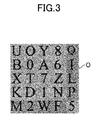
- FIG. 3 shows an original image O as an example of display data indicating content of an electronic book.
- the original image O is a 256-level gray scale image, and capital alphabet letters and numbers are described on a gray background.
- the original image O may be an image of one of pages of an electronic book.
- horizontal and vertical sizes (dimensions) of the noise image N j , the intermediate noise image M j , the modified image C j , and the original image O j are the same, and each image is a 256-level gray scale image.
- n there is an upper limit value of n in order that the human visual system works efficiently. According to the experiment of the present inventors, the upper limit value of n is about 22.
- the modified image C j also has 256 levels, and needs to be represented by pixel values displayable on the display unit 10d. As such, the following expression (3) must be satisfied. ⁇ ⁇ O x y + N j x y ⁇ ⁇
- ⁇ is the lower limit value of pixel values displayable by the display unit 10d
- ⁇ is the upper limit value of pixel values displayable by the image display means.
- the display unit 10d performs 256-level gray-scale display, and thus the lower limit value ⁇ is 0, and the upper limit value ⁇ is 255.
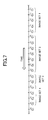
- FIG. 7 is a diagram explaining an order of modified images to be displayed on the display unit 10d.
- C j (k) indicates jth modified image of kth image set.
- a plurality of modified images included in each image set are displayed in order according to the electronic book display program.
- the number of modified images included in an image set is randomly determined for each image set, and thus the numbers may be different from one another.
- components of the noise image N j of the modified image C j are not recognized by a user, and the original image O appears to be displayed on the display unit 10d as if the original image O itself is displayed.
- FIG. 8 is a functional block diagram of the image display device 10.
- the functional block diagram shown in FIG. 8 indicates functions that the image display device 10 has and are related to display of electronic books.
- the functions shown in FIG. 8 are implemented by the image display device 10, which is a computer, executing the electronic book display program.
- the image display device 10 includes an image set generating unit 20 and a display control unit 22, and the image set generating unit 20 includes an intermediate noise image generator 20a, a noise image generator 20b, and a modified image generator 20c.
- the image set generating unit 20 sequentially generates a plurality of image sets S.
- Each image set S includes a plurality of modified images C j obtained by modifying the original image O.
- the display control unit 22 sequentially uses the image sets S generated by the image set generating unit 20 in order to sequentially display the modified images C j respectively included in the image sets S.
- a modified image C j included in an image set S which is generated most recently by the image set generating unit 20
- the image set generating unit 20 generates a subsequent image set S.
- the intermediate noise image generator 20a generates intermediate noise images M j based on the original image O.
- the noise image generator 20b generates noise images N j based on the intermediate noise images M j .
- the modified image generator 20c adds noise images N j generated by the noise image generator 20b to the original image O, thereby generating the modified images C j .
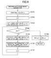
- FIG. 9 is a flow chart illustrating the processing executed by the intermediate noise image generator 20a.
- the intermediate noise image generator 20a generates a random number, and determines n, which is the number of modified images C j included in an image set, based on the random number (S101). Subsequently, the intermediate noise image generator 20a sets the variable j to 1
- the intermediate noise image generator 20a calculates L 0 (x,y) and U 0 (x,y), which respectively are initial values of the lower limit value L j (x,y) and the upper limit value U j (x,y), in the allowable range of pixel values M j (x,y) of intermediate images M j described later, for all positions (x,y) based on the following expressions (4) and (5) (S103).
- L 0 x y ⁇ - O x y
- U 0 x y ⁇ - O x y
- the intermediate noise image generator 20a calculates the lower limit values L j (x,y) and the upper limit values U j (x,y) of pixel values M j (x,y) for all positions (x,y) based on the following expressions (6) and (7) (S105).
- L j x y - ⁇ M k x y - n - j ⁇ U j - 1 x y
- U j x y - ⁇ M k x y - n - j ⁇ L j - 1 x y
- the intermediate noise image generator 20a then randomly determines M j (x,y) in the range of the lower limit value L j (x,y) and the upper limit value U j (x,y) (S106). Specifically, the intermediate noise image generator 20a generates random numbers ⁇ in the range of 0 to 1 for all positions (x,y), and calculates pixel values M j (x,y) by substituting the ⁇ for the following expression (8).
- M j x y ⁇ ⁇ L j x y + 1 - ⁇ ⁇ U j x y
- the intermediate noise image generator 20a increments the variable j by (S107), and returns to the processing of S104. If it is determined that the variable j is n or more in S104, the intermediate noise image generator 20a calculates M n (x, y) for all positions (x, y) based on the following expression (9) (S108), and finishes the processing.
- M n x y - ⁇ M k x y
- the pixel value M j (x, y) of the intermediate noise image M j satisfies the following expression similarly to the pixel value N j (x,y) of the noise image N j .
- ⁇ M j x y 0
- the expression (9) is derived from the expression (10).
- the M j (x,y) is a value obtained by inverting the sign of the sum of M 1 (x,y) to M j-1 (x,y), which have been determined in the processing of S106, and M j+1 (x,y) to M n (x,y), which are to be determined in the subsequent processing of S106.
- the upper limit value and the lower limit value of M j+1 (x, y) to M n (x, y), which are to be determined in the processing of S106 respectively are U j-1 (x, y) and L j-1 (x, y), and this leads to the expressions (6) and (7).
- FIG. 10 is a flow chart illustrating processing executed by the noise image generator 20b.
- the processing in FIG. 10 shows that the pixel values M 1 (x,y) to M n (x,y) at the positions (x,y) of the intermediate noise images M 1 to M n are randomly exchanged and thereby the pixel values N 1 (x,y) to N n (x,y) at the positions (x,y) of the noise images N 1 to N n are obtained.
- the processing shown in FIG. 10 is repeated with respect to all the positions (x, y) .
- the noise image generator 20b sets the variable t to one (S201), generates two random numbers in the range of 1 to n unless the variable t is not equal to or more than T, which is the predetermined number of repetition times (S202), and sets variable ⁇ and variable ⁇ to the generated numbers (S203). Subsequently, the noise image generator 20b exchanges the pixel value M ⁇ (x,y) of the ⁇ th intermediate noise image M ⁇ and the pixel value M ⁇ (x,y) of the ⁇ th intermediate noise image M ⁇ (S204). The noise image generator 20b then increments the variable t by 1 (S205), and returns to the processing of S202.
- the pixel values M 1 (x,y) to M n (x,y) of the intermediate noise images M 1 to M n are set to the pixel values N 1 (x,y) to N n (x, y) of the noise images N 1 to N n .
- the number of the repetition times T may be any number, but preferably equal to or more than n.
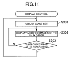
- FIG. 11 is a flow chart illustrating processing executed by the display control unit 22.
- the display control unit 22 obtains an image set S generated by the modified image generator 20c of the image set generating unit 20 (S301).
- the display control unit 22 sequentially displays, by the display unit 10d, modified images C 1 to C n included in the image set S at a predetermined time interval (S302).
- S302 a predetermined time interval
- the display control unit 22 checks whether a subsequent image set S is generated by the modified image generator 20c (S303). If it is not generated yet, the processing in S302 is executed again.
- the display control unit 22 returns to S301, obtains the latest image set S, and executes the subsequent processing.
- a plurality of image sets S are sequentially generated and the modified images C j included in the image sets S are displayed in order.
- the modified images C j of one of the image sets S are obtained by screen shots, it is not possible to restore the original image O. Since it is difficult to specify a time period in which one image set S is displayed, fraudulently obtaining the original image by screen shots can be prevented.
- the number of modified images C j included in one image set S is determined by a random number, which makes more difficult to specify a time period in which one image set S is displayed.
- this embodiment uses a plurality of image sets S, and thereby increasing the number of types of modified images presented to a user, and making it difficult for the user to restore the original image O.
- the present invention is not to be limited to the above described embodiment and can be changed as appropriate.
- a 256-level gray scale image is used as an original image O in the above example, any other form of image (e.g., color image) may of course be used.
- the original image O is not limited to an image indicating a page of an electronic book, but may be any image, such as an image included in a web page.
- the number of modified images C j included in one image set S may be fixed. Further, the image set generating unit 20 may be implemented in the electronic book server 12, instead of being implemented in the image display device 10. In this case, the electronic book server 12 may send modified images C j of image sets S to the image display device 10, and the image display device 10 may sequentially display the images for each image set.
- a generating method of the modified images C j is not limited to the above described method, but various generating methods may be employed.
- the modified images C j are obtained by adding noise to all over the original image O, although the modified images C j may be obtained by adding noise to a part of the original image O.
- an area showing particular content, such as human face or characters may be specified in the original image O, and only such area may be added with noise.
- pixel values M j (x, y) and pixel values N j (x, y) are values greater than 0 only at the positions (x, y) in the specified area, and are set to 0 at the other positions (x,y).
- an image set S is repeatedly used until a subsequent image set S is generated, and modified images C j included in the image set S are displayed, although the number of times each image set S is used in succession may be a fixed value equal to or greater than 2.
- the number of times is determined such that total display time in which an image set S is used fully exceeds generation time of the image set S.
- the number of times the image set S is used in succession may be prepared for each number n of modified images C j included in the image set S.
- the number of times the image set S is used in succession may be determined based on a random number.
Landscapes
- Engineering & Computer Science (AREA)
- Theoretical Computer Science (AREA)
- Physics & Mathematics (AREA)
- General Physics & Mathematics (AREA)
- Computer Hardware Design (AREA)
- Computer Security & Cryptography (AREA)
- Software Systems (AREA)
- General Engineering & Computer Science (AREA)
- Health & Medical Sciences (AREA)
- Bioethics (AREA)
- General Health & Medical Sciences (AREA)
- Image Processing (AREA)
- Controls And Circuits For Display Device (AREA)
Abstract
Description
- The present invention relates to an image display device, an image display method, and a program, and to a technology for preventing fraudulent acts involving acquiring an original image based on display data.
- An image displayed on a screen of an information processor, such as an image on each page of an electronic book, can be copied by taking a screen shot. That is, image data of each page of the electronic book can be obtained by storing display data stored in a display memory.
- In an attempt to prevent such fraudulent acts,
Patent Literature 1 below discloses a technology for randomly selecting S for each pixel of an original image, generating a first converted image obtained by adding S to each pixel value and a second converted image obtained by subtracting S from each pixel value, and displaying these two converted images while switching them at a high speed. In accordance with this technology, even though a viewer recognizes as if the original image is displayed, a first or a second converted image is obtained by a screen shot, and thus it is possible to prevent fraudulent acquisition of original image data. - Patent Literature 1:
JP2002-72994A - However, the technology described in the
Patent Literature 1 has a drawback that the original image can be restored by capturing screen shots to obtain the first and second converted images and averaging them. - One or more embodiments of the present invention have been conceived in view of the above, and an object thereof is to provide an image display device, an image display method, and a program that make it difficult to obtain an original image based on display data.
- In order to solve the above described problems, an image display device according to the present invention includes image set generating means for generating a plurality of image sets, each including a plurality of modified images that are obtained by modifying an original image, an average of pixel values of corresponding pixels of the plurality of modified images included in each of the image sets corresponding to a value of a corresponding pixel of the original image, and image display means for sequentially displaying the plurality of modified images included in each of the image sets by sequentially using the plurality of image sets generated by the image set generating means.
- The image set generating means may determine a number of the modified images included in the image sets based on a random number. Further, the image set generating means may generate the modified images based on a random number.
- The image set generating means may sequentially generate the plurality of image sets, and, while the plurality of modified images included in an image set generated most recently are displayed one or more times by the image display means, may generate a subsequent image set.
- An image display method according to the present invention includes an image set generating step for generating a plurality of image sets, each including a plurality of modified images that are obtained by modifying an original image, an average of pixel values of corresponding pixels of the plurality of modified images included in each of the image sets corresponding to a value of a corresponding pixel of the original image, and an image display step for sequentially displaying the plurality of modified images included in each of the image sets by sequentially using the plurality of image sets generated in the image set generating step.
- A program according to the present invention causes a computer to function as image set generating means for generating a plurality of image sets, each including a plurality of modified images that are obtained by modifying an original image, an average of pixel values of corresponding pixels of the plurality of modified images included in each of the image sets corresponding to a value of a corresponding pixel of the original image, and image display means for sequentially displaying the plurality of modified images included in each of the image sets by sequentially using the plurality of image sets generated by the image set generating means. The program may be stored in a computer-readable information storage medium, such as a CD-ROM and a DVD-ROM.
-
-
FIG. 1 is a diagram illustrating an image display device according to an embodiment of the present invention. -
FIG. 2 is a diagram illustrating a hardware configuration of the image display device. -
FIG. 3 is a diagram illustrating an example of an original image. -
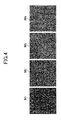
FIG. 4 is a diagram illustrating an example of an intermediate noise image. -
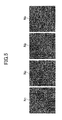
FIG. 5 is a diagram illustrating an example of a noise image. -
FIG. 6 is a diagram illustrating an example of a modified image. -
FIG. 7 is a diagram explaining an order of modified images to be displayed. -
FIG. 8 is a functional block diagram of the image display device. -
FIG. 9 is a flow chart illustrating processing for generating an intermediate noise image. -
FIG. 10 is a flow chart illustrating processing for generating a noise image. -
FIG. 11 is a flow chart illustrating display control of a modified image. - An embodiment of the present invention will be described below in detail with reference to the accompanying drawings.
-
FIG. 1 is a diagram illustrating an image display device according to an embodiment of the present invention. Theimage display device 10 is a computer in various forms, such as an electronic book reader and a tablet, and has a hardware configuration in which aCPU 10a, amain memory 10b, acommunication interface 10c, adisplay unit 10d, aninput unit 10e, and a storage unit 10f are connected to a bus, as shown inFIG. 2 . TheCPU 10a controls each section of the device and executes various processing. Themain memory 10b is volatile storage means and used for operations of theCPU 10a. Thecommunication interface 10c accesses adata communication network 14, such as the Internet, through a communication line, such as a wireless LAN and a radio telephone line. Thedisplay unit 10d is display means such as a liquid crystal display and an organic EL display. Thedisplay unit 10d includes a display memory. When theCPU 10a stores display data (raster style) in the display memory, thedisplay unit 10d displays an image indicated in the display data. Theinput unit 10e is, for example, physical keys provided to theimage display device 10, and a touch panel mounted on the display surface of thedisplay unit 10d. Data that is input by theinput unit 10e is used by theCPU 10a. The storage unit 10f is non-volatile storage means, and stores an operating system (OS), data of electronic books, and an electronic book display program for displaying the electronic books. The data of electronic books and the electronic book display program may be downloaded from thedata communication network 14, or read from a computer-readable information storage medium, such as a CD-ROM. - In this embodiment, as shown in
FIG. 1 , theimage display device 10 is connected to thedata communication network 14, to which theelectronic book server 12 is also connected. Theelectronic book server 12 is a server computer that may include a CPU, a main memory, a communication interface, and a large scale storage device, and stores data of a large number of electronic books. In response to a request from theimage display device 10, theelectronic book server 12 sends the data of electronic books to theimage display device 10. Theimage display device 10 stores the received electronic book data in the storage unit 10f. The electronic book display program causes thedisplay unit 10d to display the data of electronic books stored in the storage unit 10f. In addition, the electronic book display program executes processing, such as page feeding, in accordance with a user's operation of theinput unit 10e. - The OS is performed in the
image display device 10, and the OS provides a screen shot function. According to the screen shot function, when a user performs specific operation using theinput unit 10e, the display data stored in the display memory built in thedisplay unit 10d is moved to the storage unit 10f. In this way, the display data stored in the storage unit 10f can be redisplayed by thedisplay unit 10d later. Further, the display data can be sent to other image display devices by thecommunication interface 10c. When the data of electronic books sent from theelectronic book server 12 is displayed on thedisplay unit 10d, the display data of electronic books is stored in the display memory. With use of the screen shot function provided by the OS, the display data can be moved to the storage unit 10f, and eventually sent to other image display devices. - In order to prevent such fraudulent acts, the electronic book display program stores display data (modified image), which is obtained by adding noise to display data (original image) of an original electronic book, into the display memory of the
display unit 10. As such, even though the screen shot function provided by the OS is used, only data of the electronic book added with noise can be moved to the storage unit 10f. In this regard, a plurality types of data of the electronic book added with noise are prepared, and an average value of the plurality types of data matches the data of original electronic book. As such, the plurality types of data of the electronic book added with noise are switched at short intervals and sequentially displayed, and thereby allowing the user to recognize data of original electronic book without noise as if it were displayed on thedisplay unit 10d. -
FIG. 3 shows an original image O as an example of display data indicating content of an electronic book. Here, the original image O is a 256-level gray scale image, and capital alphabet letters and numbers are described on a gray background. The original image O may be an image of one of pages of an electronic book. - When the pixel value of the position (x,y) of the original image O is O (x, y), such pixel value is in the range of 0 to 255 inclusive. The pixel value O (x,y) of the position in the background is 1 or more and less than 255, and may be, for example, about 30. On the other hand, the pixel value O (x,y) of the position in the letters and numbers is greater than such value, and may be, for example, about 200. The
image display device 10 may receive the original image O in an encrypted form from theelectronic book server 12. While the original image O is provided to the user, the electronic book display program of theimage display device 10 continues to generate image sets S based on the original image O. Here, each image set S includes n (n≧2) types of modified images Cj (j=1-n). - Specifically, the electronic book display program generates n types of noise images Nj (j=1-n), and adds the generated noise images to the original image 0, thereby obtaining n types of modified images Cj (j=1-n). Further, in order to generate n types of noise images Nj, the electronic book display program generates n types of intermediate noise images Mj (j=1-n), and then converts the generated intermediate noise images into n types of noise images Nj. In this regard, the electronic book display program randomly determines n for each image set S. The electronic book display program also randomly determines intermediate noise image Mj and noise image Nj under the condition described later.
-
FIGs. 4 to 6 respectively show examples of intermediate noise images M1 to M4, noise images N1 to N4, and modified images C1 to C4, where n=4. Here, horizontal and vertical sizes (dimensions) of the noise image Nj, the intermediate noise image Mj, the modified image Cj, and the original image Oj are the same, and each image is a 256-level gray scale image. - When the pixel value of the noise image Nj at the position (x,y) is Nj (x,y), and the pixel value of the modified image Cj at the position (x,y) is Cj (x,y), the following expression (1) is satisfied.

- When all of the n types of noise images Nj are viewed while being switched at short intervals, due to the human visual system, viewers perceive as if no image is displayed. That is, the following expression (2) is satisfied at any position (x, y) of the noise image Nj.

- Here, ∑ is a sum from j=1 to j=n. Since the expressions (1) and (2) are satisfied, the average of pixel values Cj (x,y) at any position (x,y) of the modified image Cj matches the pixel value O (x, y) of the position (x, y) of the original image O. In this regard, there is an upper limit value of n in order that the human visual system works efficiently. According to the experiment of the present inventors, the upper limit value of n is about 22.
- As described above, the modified image Cj also has 256 levels, and needs to be represented by pixel values displayable on the
display unit 10d. As such, the following expression (3) must be satisfied.
- Here, α is the lower limit value of pixel values displayable by the
display unit 10d, and β is the upper limit value of pixel values displayable by the image display means. Thedisplay unit 10d performs 256-level gray-scale display, and thus the lower limit value α is 0, and the upper limit value β is 255. - For each time an image set S is generated, the electronic book display program of the
image display device 10 displays modified images C1 to Cn included in the generated image set in order.FIG. 7 is a diagram explaining an order of modified images to be displayed on thedisplay unit 10d. InFIG. 7 , Cj (k) indicates jth modified image of kth image set. As shown inFIG. 7 , a plurality of modified images included in each image set are displayed in order according to the electronic book display program. Here, the number of modified images included in an image set is randomly determined for each image set, and thus the numbers may be different from one another. As described above, components of the noise image Nj of the modified image Cj are not recognized by a user, and the original image O appears to be displayed on thedisplay unit 10d as if the original image O itself is displayed. -
FIG. 8 is a functional block diagram of theimage display device 10. The functional block diagram shown inFIG. 8 indicates functions that theimage display device 10 has and are related to display of electronic books. The functions shown inFIG. 8 are implemented by theimage display device 10, which is a computer, executing the electronic book display program. - As shown in
FIG. 8 , theimage display device 10 includes an imageset generating unit 20 and adisplay control unit 22, and the image set generatingunit 20 includes an intermediatenoise image generator 20a, anoise image generator 20b, and a modifiedimage generator 20c. - The image
set generating unit 20 sequentially generates a plurality of image sets S. Each image set S includes a plurality of modified images Cj obtained by modifying the original image O. Thedisplay control unit 22 sequentially uses the image sets S generated by the image set generatingunit 20 in order to sequentially display the modified images Cj respectively included in the image sets S. Here, while a modified image Cj included in an image set S, which is generated most recently by the image set generatingunit 20, is displayed by thedisplay control unit 22 one or more times, the image set generatingunit 20 generates a subsequent image set S. The intermediatenoise image generator 20a generates intermediate noise images Mj based on the original image O. Thenoise image generator 20b generates noise images Nj based on the intermediate noise images Mj. As shown in the expression (1), the modifiedimage generator 20c adds noise images Nj generated by thenoise image generator 20b to the original image O, thereby generating the modified images Cj. - In the following, processing executed by the intermediate
noise image generator 20a will be explained in detail.FIG. 9 is a flow chart illustrating the processing executed by the intermediatenoise image generator 20a. As shown inFIG. 9 , the intermediatenoise image generator 20a generates a random number, and determines n, which is the number of modified images Cj included in an image set, based on the random number (S101). Subsequently, the intermediatenoise image generator 20a sets the variable j to 1 - (S102). Further, the intermediate
noise image generator 20a calculates L0 (x,y) and U0 (x,y), which respectively are initial values of the lower limit value Lj (x,y) and the upper limit value Uj (x,y), in the allowable range of pixel values Mj (x,y) of intermediate images Mj described later, for all positions (x,y) based on the following expressions (4) and (5) (S103).

- Subsequently, if the variable j is not equal to or more than n (S104), the intermediate
noise image generator 20a calculates the lower limit values Lj (x,y) and the upper limit values Uj (x,y) of pixel values Mj (x,y) for all positions (x,y) based on the following expressions (6) and (7) (S105). Here, ∑ is a sum from k=1 to j-1.

- The intermediate
noise image generator 20a then randomly determines Mj (x,y) in the range of the lower limit value Lj (x,y) and the upper limit value Uj (x,y) (S106). Specifically, the intermediatenoise image generator 20a generates random numbers γ in the range of 0 to 1 for all positions (x,y), and calculates pixel values Mj (x,y) by substituting the γ for the following expression (8).
- Subsequently, the intermediate
noise image generator 20a increments the variable j by (S107), and returns to the processing of S104. If it is determined that the variable j is n or more in S104, the intermediatenoise image generator 20a calculates Mn (x, y) for all positions (x, y) based on the following expression (9) (S108), and finishes the processing. Here, ∑ is a sum from k=1 to n-1.
- The pixel value Mj (x, y) of the intermediate noise image Mj satisfies the following expression similarly to the pixel value Nj (x,y) of the noise image Nj. Here, ∑ is a sum from j=1 to n.

- The expression (9) is derived from the expression (10). The Mj (x,y) is a value obtained by inverting the sign of the sum of M1 (x,y) to Mj-1 (x,y), which have been determined in the processing of S106, and Mj+1 (x,y) to Mn (x,y), which are to be determined in the subsequent processing of S106. Here, assuming that the upper limit value and the lower limit value of Mj+1 (x, y) to Mn (x, y), which are to be determined in the processing of S106, respectively are Uj-1 (x, y) and Lj-1 (x, y), and this leads to the expressions (6) and (7).
- Next, processing of the
noise image generator 20b will be explained in detail.FIG. 10 is a flow chart illustrating processing executed by thenoise image generator 20b. The processing inFIG. 10 shows that the pixel values M1 (x,y) to Mn (x,y) at the positions (x,y) of the intermediate noise images M1 to Mn are randomly exchanged and thereby the pixel values N1 (x,y) to Nn (x,y) at the positions (x,y) of the noise images N1 to Nn are obtained. The processing shown inFIG. 10 is repeated with respect to all the positions (x, y) . In this processing, thenoise image generator 20b sets the variable t to one (S201), generates two random numbers in the range of 1 to n unless the variable t is not equal to or more than T, which is the predetermined number of repetition times (S202), and sets variable δ and variable ε to the generated numbers (S203). Subsequently, thenoise image generator 20b exchanges the pixel value Mδ (x,y) of the δth intermediate noise image Mδ and the pixel value Mε (x,y) of the εth intermediate noise image Mε (S204). Thenoise image generator 20b then increments the variable t by 1 (S205), and returns to the processing of S202. In the processing of S202, if it is determined that the variable t is equal to or more than the repetition times T, the pixel values M1 (x,y) to Mn (x,y) of the intermediate noise images M1 to Mn are set to the pixel values N1 (x,y) to Nn (x, y) of the noise images N1 to Nn. - Subsequently, the processing of S201 to S206 is repeated for all of the positions (x,y). The number of the repetition times T may be any number, but preferably equal to or more than n.
- Next, processing of the
display control unit 22 will be explained in detail.FIG. 11 is a flow chart illustrating processing executed by thedisplay control unit 22. As shown inFIG. 11 , thedisplay control unit 22 obtains an image set S generated by the modifiedimage generator 20c of the image set generating unit 20 (S301). Thedisplay control unit 22 sequentially displays, by thedisplay unit 10d, modified images C1 to Cn included in the image set S at a predetermined time interval (S302). When all of the modified images C1 to Cn are displayed, thedisplay control unit 22 checks whether a subsequent image set S is generated by the modifiedimage generator 20c (S303). If it is not generated yet, the processing in S302 is executed again. If the subsequent image set S is generated, thedisplay control unit 22 returns to S301, obtains the latest image set S, and executes the subsequent processing. According to theimage display device 10 described above, a plurality of image sets S are sequentially generated and the modified images Cj included in the image sets S are displayed in order. As such, among from the images displayed one after another, unless all of the modified images Cj of one of the image sets S are obtained by screen shots, it is not possible to restore the original image O. Since it is difficult to specify a time period in which one image set S is displayed, fraudulently obtaining the original image by screen shots can be prevented. - Specifically, in the above embodiment, the number of modified images Cj included in one image set S is determined by a random number, which makes more difficult to specify a time period in which one image set S is displayed.
- Further, as described above, there is a limit of the number n (about 22) of modified images Cj included in one image set S. As such, if one image set S is repeatedly presented to a user, the user may highly likely obtain all types of the modified images Cj and restore the original image O. On the other hand, this embodiment uses a plurality of image sets S, and thereby increasing the number of types of modified images presented to a user, and making it difficult for the user to restore the original image O.
- The present invention is not to be limited to the above described embodiment and can be changed as appropriate. For example, although a 256-level gray scale image is used as an original image O in the above example, any other form of image (e.g., color image) may of course be used. In addition, the original image O is not limited to an image indicating a page of an electronic book, but may be any image, such as an image included in a web page.
- The number of modified images Cj included in one image set S may be fixed. Further, the image set generating
unit 20 may be implemented in theelectronic book server 12, instead of being implemented in theimage display device 10. In this case, theelectronic book server 12 may send modified images Cj of image sets S to theimage display device 10, and theimage display device 10 may sequentially display the images for each image set. - Further, a generating method of the modified images Cj is not limited to the above described method, but various generating methods may be employed. According to the above embodiment, the modified images Cj are obtained by adding noise to all over the original image O, although the modified images Cj may be obtained by adding noise to a part of the original image O. For example, an area showing particular content, such as human face or characters, may be specified in the original image O, and only such area may be added with noise. In this case, pixel values Mj (x, y) and pixel values Nj (x, y) are values greater than 0 only at the positions (x, y) in the specified area, and are set to 0 at the other positions (x,y). Further, in the above discussion, an image set S is repeatedly used until a subsequent image set S is generated, and modified images Cj included in the image set S are displayed, although the number of times each image set S is used in succession may be a fixed value equal to or greater than 2.
- In this case, preferably the number of times is determined such that total display time in which an image set S is used fully exceeds generation time of the image set S. In addition, the number of times the image set S is used in succession may be prepared for each number n of modified images Cj included in the image set S. Alternatively, the number of times the image set S is used in succession may be determined based on a random number.
Claims (10)
- An image display device, comprising:image set generating means for generating a plurality of image sets, each including a plurality of modified images that are obtained by modifying an original image, an average of pixel values of corresponding pixels of the plurality of modified images included in each of the image sets corresponding to a value of a corresponding pixel of the original image; andimage display means for sequentially displaying the plurality of modified images included in each of the image sets by sequentially using the plurality of image sets generated by the image set generating means.
- The image display device according to claim 1, wherein the image set generating means determines a number of the modified images included in the image sets based on a random number.
- The image display device according to claim 1 or 2, wherein the image set generating means generates the modified images based on a random number.
- The image display device according to any one of claims 1 to 3, wherein the image set generating means sequentially generates the plurality of image sets, and, while the plurality of modified images included in an image set generated most recently are displayed one or more times by the image display means, generates a subsequent image set.
- The image display device according to any one of claims 1 to 4, wherein, when a pixel value at a position (x, y) of an original image O is O (x, y), a pixel value at a position (x, y) of jth modified image Cj included in the image sets is Cj (x,y), and a pixel value at a position (x, y) of jth noise image Nj included in the image sets is Nj (x,y), the following expression is established:


- The image display device according to claim 5, wherein the following expression is established:

- The image display device according to claim 6, wherein, when a pixel value at a position (x,y) of jth intermediate noise image Mj is Mj (x,y), a lower limit value Lj (x,y) and a upper limit value Uj (x,y) of the pixel value are sequentially calculated by


- The image display device according to claim 7, wherein a pixel value Mδ (x,y) at a position (x,y) of δth intermediate noise image Mδ and a pixel value Mε (x,y) at a position (x,y) of εth intermediate noise image Mε are interchanged so as to generate the plurality of noise images Nj, and whereby the plurality of modified images Cj are generated (where γ and δ are random numbers in a range of 1 to n inclusive).
- An image display method, comprising:an image set generating step for generating a plurality of image sets, each including a plurality of modified images that are obtained by modifying an original image, an average of pixel values of corresponding pixels of the plurality of modified images included in each of the image sets corresponding to a value of a corresponding pixel of the original image; andan image display step for sequentially displaying the plurality of modified images included in each of the image sets by sequentially using the plurality of image sets generated in the image set generating step.
- A program for causing a computer to function as:image set generating means for generating a plurality of image sets, each including a plurality of modified images that are obtained by modifying an original image, an average of pixel values of corresponding pixels of the plurality of modified images included in each of the image sets corresponding to a value of a corresponding pixel of the original image; andimage display means for sequentially displaying the plurality of modified images included in each of the image sets by sequentially using the plurality of image sets generated by the image set generating means.
Applications Claiming Priority (1)
| Application Number | Priority Date | Filing Date | Title |
|---|---|---|---|
| PCT/JP2013/052275 WO2014118960A1 (en) | 2013-01-31 | 2013-01-31 | Image display device, image display method and program |
Publications (3)
| Publication Number | Publication Date |
|---|---|
| EP2953128A1 true EP2953128A1 (en) | 2015-12-09 |
| EP2953128A4 EP2953128A4 (en) | 2016-08-31 |
| EP2953128B1 EP2953128B1 (en) | 2017-07-26 |
Family
ID=51261704
Family Applications (1)
| Application Number | Title | Priority Date | Filing Date |
|---|---|---|---|
| EP13873900.8A Active EP2953128B1 (en) | 2013-01-31 | 2013-01-31 | Image display device, image display method and program |
Country Status (5)
| Country | Link |
|---|---|
| US (1) | US9666117B2 (en) |
| EP (1) | EP2953128B1 (en) |
| JP (1) | JP5824170B2 (en) |
| ES (1) | ES2642412T3 (en) |
| WO (1) | WO2014118960A1 (en) |
Families Citing this family (2)
| Publication number | Priority date | Publication date | Assignee | Title |
|---|---|---|---|---|
| EP2992526A1 (en) * | 2013-04-30 | 2016-03-09 | Sioptica GmbH | Display screen and method for secure representation of information |
| JP7479887B2 (en) * | 2020-03-19 | 2024-05-09 | セコム株式会社 | Image generating device, image processing system, and image processing method |
Family Cites Families (12)
| Publication number | Priority date | Publication date | Assignee | Title |
|---|---|---|---|---|
| AU702353B2 (en) * | 1995-03-07 | 1999-02-18 | Nec Corporation | System and method for perspective representation |
| JP3541714B2 (en) * | 1999-03-04 | 2004-07-14 | 日本電気株式会社 | Image display device |
| JP3581048B2 (en) | 1999-06-29 | 2004-10-27 | 三菱電機株式会社 | Contaminated content distribution system, contaminated content using apparatus, and contaminated content using method |
| JP3577455B2 (en) | 2000-08-28 | 2004-10-13 | 日本電信電話株式会社 | Image processing method and apparatus, and recording medium storing image processing program |
| AU2002316067A1 (en) * | 2001-05-02 | 2002-11-11 | Bitstream Inc. | Methods, systems, and programming for producing and displaying subpixel-optimized font bitmaps using non-linear color balancing |
| JP4219725B2 (en) * | 2003-04-15 | 2009-02-04 | パナソニック株式会社 | Image display method, image display system, image data conversion device, and image display device |
| JP4181593B2 (en) * | 2006-09-20 | 2008-11-19 | シャープ株式会社 | Image display apparatus and method |
| JP4696099B2 (en) * | 2007-08-07 | 2011-06-08 | 日立オムロンターミナルソリューションズ株式会社 | Display image converter |
| JP2009205198A (en) * | 2008-02-26 | 2009-09-10 | Nec Corp | Image processing device, method and program |
| JP4950316B2 (en) * | 2010-02-26 | 2012-06-13 | 楽天株式会社 | DATA GENERATION DEVICE, DATA GENERATION METHOD, AND DATA GENERATION PROGRAM |
| US20120057850A1 (en) * | 2010-09-03 | 2012-03-08 | Rovi Technologies Corporation | Systems and methods for generating and embedding personalized media content |
| US20130201099A1 (en) * | 2012-02-02 | 2013-08-08 | Orto, Inc. | Method and system for providing a modified display image augmented for various viewing angles |
-
2013
- 2013-01-31 ES ES13873900.8T patent/ES2642412T3/en active Active
- 2013-01-31 EP EP13873900.8A patent/EP2953128B1/en active Active
- 2013-01-31 WO PCT/JP2013/052275 patent/WO2014118960A1/en not_active Ceased
- 2013-01-31 JP JP2014559451A patent/JP5824170B2/en active Active
- 2013-01-31 US US14/764,984 patent/US9666117B2/en active Active
Also Published As
| Publication number | Publication date |
|---|---|
| ES2642412T3 (en) | 2017-11-16 |
| JP5824170B2 (en) | 2015-11-25 |
| EP2953128B1 (en) | 2017-07-26 |
| JPWO2014118960A1 (en) | 2017-01-26 |
| EP2953128A4 (en) | 2016-08-31 |
| US9666117B2 (en) | 2017-05-30 |
| US20150371582A1 (en) | 2015-12-24 |
| WO2014118960A1 (en) | 2014-08-07 |
Similar Documents
| Publication | Publication Date | Title |
|---|---|---|
| EP3965431B1 (en) | Video data processing method and related device | |
| EP3614660B1 (en) | Video image processing method and device | |
| CN109254813B (en) | Screen adaptation method, device, computer equipment and storage medium | |
| EP2420955A2 (en) | Terminal device and method for augmented reality | |
| US10079005B2 (en) | Display substrate, display device and resolution adjustment method for display substrate | |
| US20150186662A1 (en) | Method and apparatus for input verification | |
| EP3114601B1 (en) | Access control for a resource | |
| US9030378B2 (en) | Sharing display processing system, display processing system, and display method | |
| US20140304580A1 (en) | Adjusting layout size of hyperlink | |
| CN113158167B (en) | Verification code implementation method, electronic equipment and computer readable storage medium | |
| EP2953128B1 (en) | Image display device, image display method and program | |
| US20160020902A1 (en) | Key Generating Method and Apparatus | |
| CN105678688B (en) | Picture processing method and device | |
| CN104123062B (en) | A kind of information processing method and electronic equipment | |
| US20160357395A1 (en) | Information processing device, non-transitory computer-readable recording medium storing an information processing program, and information processing method | |
| CN112333329B (en) | Unread information reminding method and device and electronic equipment | |
| CN102063260B (en) | Method and device for displaying screen | |
| CN108681531B (en) | Document input control method and device | |
| CN113721818B (en) | Image processing method, device, equipment and computer readable storage medium | |
| CN117742557A (en) | Information display control method and device | |
| CN104035667A (en) | Candidate message display method and device | |
| CN116959055A (en) | A face recognition method, device and storage medium | |
| CN104571843A (en) | Information processing method and electronic equipment | |
| US20250077186A1 (en) | Method and device for generating random number | |
| CN105472143A (en) | Privacy protection equipment of mobile device and privacy protection method thereof |
Legal Events
| Date | Code | Title | Description |
|---|---|---|---|
| PUAI | Public reference made under article 153(3) epc to a published international application that has entered the european phase |
Free format text: ORIGINAL CODE: 0009012 |
|
| 17P | Request for examination filed |
Effective date: 20150812 |
|
| AK | Designated contracting states |
Kind code of ref document: A1 Designated state(s): AL AT BE BG CH CY CZ DE DK EE ES FI FR GB GR HR HU IE IS IT LI LT LU LV MC MK MT NL NO PL PT RO RS SE SI SK SM TR |
|
| AX | Request for extension of the european patent |
Extension state: BA ME |
|
| DAX | Request for extension of the european patent (deleted) | ||
| A4 | Supplementary search report drawn up and despatched |
Effective date: 20160729 |
|
| RIC1 | Information provided on ipc code assigned before grant |
Ipc: G09G 5/00 20060101AFI20160725BHEP |
|
| GRAP | Despatch of communication of intention to grant a patent |
Free format text: ORIGINAL CODE: EPIDOSNIGR1 |
|
| INTG | Intention to grant announced |
Effective date: 20170331 |
|
| GRAS | Grant fee paid |
Free format text: ORIGINAL CODE: EPIDOSNIGR3 |
|
| GRAA | (expected) grant |
Free format text: ORIGINAL CODE: 0009210 |
|
| AK | Designated contracting states |
Kind code of ref document: B1 Designated state(s): AL AT BE BG CH CY CZ DE DK EE ES FI FR GB GR HR HU IE IS IT LI LT LU LV MC MK MT NL NO PL PT RO RS SE SI SK SM TR |
|
| REG | Reference to a national code |
Ref country code: GB Ref legal event code: FG4D |
|
| REG | Reference to a national code |
Ref country code: CH Ref legal event code: EP |
|
| REG | Reference to a national code |
Ref country code: AT Ref legal event code: REF Ref document number: 912969 Country of ref document: AT Kind code of ref document: T Effective date: 20170815 |
|
| REG | Reference to a national code |
Ref country code: IE Ref legal event code: FG4D |
|
| REG | Reference to a national code |
Ref country code: DE Ref legal event code: R096 Ref document number: 602013024232 Country of ref document: DE |
|
| REG | Reference to a national code |
Ref country code: ES Ref legal event code: FG2A Ref document number: 2642412 Country of ref document: ES Kind code of ref document: T3 Effective date: 20171116 |
|
| REG | Reference to a national code |
Ref country code: NL Ref legal event code: MP Effective date: 20170726 |
|
| REG | Reference to a national code |
Ref country code: LT Ref legal event code: MG4D |
|
| REG | Reference to a national code |
Ref country code: FR Ref legal event code: PLFP Year of fee payment: 6 |
|
| PG25 | Lapsed in a contracting state [announced via postgrant information from national office to epo] |
Ref country code: LT Free format text: LAPSE BECAUSE OF FAILURE TO SUBMIT A TRANSLATION OF THE DESCRIPTION OR TO PAY THE FEE WITHIN THE PRESCRIBED TIME-LIMIT Effective date: 20170726 Ref country code: NL Free format text: LAPSE BECAUSE OF FAILURE TO SUBMIT A TRANSLATION OF THE DESCRIPTION OR TO PAY THE FEE WITHIN THE PRESCRIBED TIME-LIMIT Effective date: 20170726 Ref country code: HR Free format text: LAPSE BECAUSE OF FAILURE TO SUBMIT A TRANSLATION OF THE DESCRIPTION OR TO PAY THE FEE WITHIN THE PRESCRIBED TIME-LIMIT Effective date: 20170726 Ref country code: SE Free format text: LAPSE BECAUSE OF FAILURE TO SUBMIT A TRANSLATION OF THE DESCRIPTION OR TO PAY THE FEE WITHIN THE PRESCRIBED TIME-LIMIT Effective date: 20170726 Ref country code: NO Free format text: LAPSE BECAUSE OF FAILURE TO SUBMIT A TRANSLATION OF THE DESCRIPTION OR TO PAY THE FEE WITHIN THE PRESCRIBED TIME-LIMIT Effective date: 20171026 Ref country code: FI Free format text: LAPSE BECAUSE OF FAILURE TO SUBMIT A TRANSLATION OF THE DESCRIPTION OR TO PAY THE FEE WITHIN THE PRESCRIBED TIME-LIMIT Effective date: 20170726 |
|
| PG25 | Lapsed in a contracting state [announced via postgrant information from national office to epo] |
Ref country code: PL Free format text: LAPSE BECAUSE OF FAILURE TO SUBMIT A TRANSLATION OF THE DESCRIPTION OR TO PAY THE FEE WITHIN THE PRESCRIBED TIME-LIMIT Effective date: 20170726 Ref country code: BG Free format text: LAPSE BECAUSE OF FAILURE TO SUBMIT A TRANSLATION OF THE DESCRIPTION OR TO PAY THE FEE WITHIN THE PRESCRIBED TIME-LIMIT Effective date: 20171026 Ref country code: LV Free format text: LAPSE BECAUSE OF FAILURE TO SUBMIT A TRANSLATION OF THE DESCRIPTION OR TO PAY THE FEE WITHIN THE PRESCRIBED TIME-LIMIT Effective date: 20170726 Ref country code: RS Free format text: LAPSE BECAUSE OF FAILURE TO SUBMIT A TRANSLATION OF THE DESCRIPTION OR TO PAY THE FEE WITHIN THE PRESCRIBED TIME-LIMIT Effective date: 20170726 Ref country code: GR Free format text: LAPSE BECAUSE OF FAILURE TO SUBMIT A TRANSLATION OF THE DESCRIPTION OR TO PAY THE FEE WITHIN THE PRESCRIBED TIME-LIMIT Effective date: 20171027 Ref country code: IS Free format text: LAPSE BECAUSE OF FAILURE TO SUBMIT A TRANSLATION OF THE DESCRIPTION OR TO PAY THE FEE WITHIN THE PRESCRIBED TIME-LIMIT Effective date: 20171126 |
|
| PG25 | Lapsed in a contracting state [announced via postgrant information from national office to epo] |
Ref country code: RO Free format text: LAPSE BECAUSE OF FAILURE TO SUBMIT A TRANSLATION OF THE DESCRIPTION OR TO PAY THE FEE WITHIN THE PRESCRIBED TIME-LIMIT Effective date: 20170726 Ref country code: DK Free format text: LAPSE BECAUSE OF FAILURE TO SUBMIT A TRANSLATION OF THE DESCRIPTION OR TO PAY THE FEE WITHIN THE PRESCRIBED TIME-LIMIT Effective date: 20170726 Ref country code: CZ Free format text: LAPSE BECAUSE OF FAILURE TO SUBMIT A TRANSLATION OF THE DESCRIPTION OR TO PAY THE FEE WITHIN THE PRESCRIBED TIME-LIMIT Effective date: 20170726 |
|
| REG | Reference to a national code |
Ref country code: DE Ref legal event code: R097 Ref document number: 602013024232 Country of ref document: DE |
|
| PG25 | Lapsed in a contracting state [announced via postgrant information from national office to epo] |
Ref country code: SK Free format text: LAPSE BECAUSE OF FAILURE TO SUBMIT A TRANSLATION OF THE DESCRIPTION OR TO PAY THE FEE WITHIN THE PRESCRIBED TIME-LIMIT Effective date: 20170726 Ref country code: SM Free format text: LAPSE BECAUSE OF FAILURE TO SUBMIT A TRANSLATION OF THE DESCRIPTION OR TO PAY THE FEE WITHIN THE PRESCRIBED TIME-LIMIT Effective date: 20170726 Ref country code: IT Free format text: LAPSE BECAUSE OF FAILURE TO SUBMIT A TRANSLATION OF THE DESCRIPTION OR TO PAY THE FEE WITHIN THE PRESCRIBED TIME-LIMIT Effective date: 20170726 Ref country code: EE Free format text: LAPSE BECAUSE OF FAILURE TO SUBMIT A TRANSLATION OF THE DESCRIPTION OR TO PAY THE FEE WITHIN THE PRESCRIBED TIME-LIMIT Effective date: 20170726 |
|
| PLBE | No opposition filed within time limit |
Free format text: ORIGINAL CODE: 0009261 |
|
| STAA | Information on the status of an ep patent application or granted ep patent |
Free format text: STATUS: NO OPPOSITION FILED WITHIN TIME LIMIT |
|
| 26N | No opposition filed |
Effective date: 20180430 |
|
| PG25 | Lapsed in a contracting state [announced via postgrant information from national office to epo] |
Ref country code: SI Free format text: LAPSE BECAUSE OF FAILURE TO SUBMIT A TRANSLATION OF THE DESCRIPTION OR TO PAY THE FEE WITHIN THE PRESCRIBED TIME-LIMIT Effective date: 20170726 |
|
| REG | Reference to a national code |
Ref country code: CH Ref legal event code: PL |
|
| PG25 | Lapsed in a contracting state [announced via postgrant information from national office to epo] |
Ref country code: LU Free format text: LAPSE BECAUSE OF NON-PAYMENT OF DUE FEES Effective date: 20180131 |
|
| REG | Reference to a national code |
Ref country code: IE Ref legal event code: MM4A |
|
| REG | Reference to a national code |
Ref country code: BE Ref legal event code: MM Effective date: 20180131 |
|
| PG25 | Lapsed in a contracting state [announced via postgrant information from national office to epo] |
Ref country code: LI Free format text: LAPSE BECAUSE OF NON-PAYMENT OF DUE FEES Effective date: 20180131 Ref country code: BE Free format text: LAPSE BECAUSE OF NON-PAYMENT OF DUE FEES Effective date: 20180131 Ref country code: CH Free format text: LAPSE BECAUSE OF NON-PAYMENT OF DUE FEES Effective date: 20180131 |
|
| PG25 | Lapsed in a contracting state [announced via postgrant information from national office to epo] |
Ref country code: IE Free format text: LAPSE BECAUSE OF NON-PAYMENT OF DUE FEES Effective date: 20180131 |
|
| PG25 | Lapsed in a contracting state [announced via postgrant information from national office to epo] |
Ref country code: MC Free format text: LAPSE BECAUSE OF FAILURE TO SUBMIT A TRANSLATION OF THE DESCRIPTION OR TO PAY THE FEE WITHIN THE PRESCRIBED TIME-LIMIT Effective date: 20170726 |
|
| PG25 | Lapsed in a contracting state [announced via postgrant information from national office to epo] |
Ref country code: MT Free format text: LAPSE BECAUSE OF NON-PAYMENT OF DUE FEES Effective date: 20180131 |
|
| PG25 | Lapsed in a contracting state [announced via postgrant information from national office to epo] |
Ref country code: TR Free format text: LAPSE BECAUSE OF FAILURE TO SUBMIT A TRANSLATION OF THE DESCRIPTION OR TO PAY THE FEE WITHIN THE PRESCRIBED TIME-LIMIT Effective date: 20170726 |
|
| PG25 | Lapsed in a contracting state [announced via postgrant information from national office to epo] |
Ref country code: PT Free format text: LAPSE BECAUSE OF FAILURE TO SUBMIT A TRANSLATION OF THE DESCRIPTION OR TO PAY THE FEE WITHIN THE PRESCRIBED TIME-LIMIT Effective date: 20170726 |
|
| PG25 | Lapsed in a contracting state [announced via postgrant information from national office to epo] |
Ref country code: HU Free format text: LAPSE BECAUSE OF FAILURE TO SUBMIT A TRANSLATION OF THE DESCRIPTION OR TO PAY THE FEE WITHIN THE PRESCRIBED TIME-LIMIT; INVALID AB INITIO Effective date: 20130131 Ref country code: MK Free format text: LAPSE BECAUSE OF NON-PAYMENT OF DUE FEES Effective date: 20170726 Ref country code: CY Free format text: LAPSE BECAUSE OF FAILURE TO SUBMIT A TRANSLATION OF THE DESCRIPTION OR TO PAY THE FEE WITHIN THE PRESCRIBED TIME-LIMIT Effective date: 20170726 |
|
| PG25 | Lapsed in a contracting state [announced via postgrant information from national office to epo] |
Ref country code: AL Free format text: LAPSE BECAUSE OF FAILURE TO SUBMIT A TRANSLATION OF THE DESCRIPTION OR TO PAY THE FEE WITHIN THE PRESCRIBED TIME-LIMIT Effective date: 20170726 |
|
| REG | Reference to a national code |
Ref country code: AT Ref legal event code: UEP Ref document number: 912969 Country of ref document: AT Kind code of ref document: T Effective date: 20170726 |
|
| REG | Reference to a national code |
Ref country code: DE Ref legal event code: R082 Ref document number: 602013024232 Country of ref document: DE Representative=s name: DENNEMEYER & ASSOCIATES RECHTSANWALTSGESELLSCH, DE Ref country code: DE Ref legal event code: R081 Ref document number: 602013024232 Country of ref document: DE Owner name: RAKUTEN GROUP, INC., JP Free format text: FORMER OWNER: RAKUTEN, INC., TOKYO, JP Ref country code: DE Ref legal event code: R082 Ref document number: 602013024232 Country of ref document: DE Representative=s name: DENNEMEYER & ASSOCIATES S.A., DE |
|
| REG | Reference to a national code |
Ref country code: ES Ref legal event code: PC2A Owner name: RAKUTEN GROUP, INC. Effective date: 20220121 |
|
| REG | Reference to a national code |
Ref country code: AT Ref legal event code: HC Ref document number: 912969 Country of ref document: AT Kind code of ref document: T Owner name: RAKUTEN GROUP, INC., JP Effective date: 20220719 |
|
| REG | Reference to a national code |
Ref country code: DE Ref legal event code: R082 Ref document number: 602013024232 Country of ref document: DE Representative=s name: DENNEMEYER & ASSOCIATES RECHTSANWALTSGESELLSCH, DE |
|
| PGFP | Annual fee paid to national office [announced via postgrant information from national office to epo] |
Ref country code: GB Payment date: 20251220 Year of fee payment: 14 |
|
| PGFP | Annual fee paid to national office [announced via postgrant information from national office to epo] |
Ref country code: FR Payment date: 20251217 Year of fee payment: 14 |
|
| PGFP | Annual fee paid to national office [announced via postgrant information from national office to epo] |
Ref country code: ES Payment date: 20260202 Year of fee payment: 14 |
|
| PGFP | Annual fee paid to national office [announced via postgrant information from national office to epo] |
Ref country code: DE Payment date: 20251217 Year of fee payment: 14 |
|
| PGFP | Annual fee paid to national office [announced via postgrant information from national office to epo] |
Ref country code: AT Payment date: 20251218 Year of fee payment: 14 |