EP2953072A1 - Workflow test case generation - Google Patents
Workflow test case generation Download PDFInfo
- Publication number
- EP2953072A1 EP2953072A1 EP15171011.8A EP15171011A EP2953072A1 EP 2953072 A1 EP2953072 A1 EP 2953072A1 EP 15171011 A EP15171011 A EP 15171011A EP 2953072 A1 EP2953072 A1 EP 2953072A1
- Authority
- EP
- European Patent Office
- Prior art keywords
- workflow
- test
- building block
- generate
- test case
- Prior art date
- Legal status (The legal status is an assumption and is not a legal conclusion. Google has not performed a legal analysis and makes no representation as to the accuracy of the status listed.)
- Ceased
Links
Images















Classifications
-
- G—PHYSICS
- G06—COMPUTING OR CALCULATING; COUNTING
- G06Q—INFORMATION AND COMMUNICATION TECHNOLOGY [ICT] SPECIALLY ADAPTED FOR ADMINISTRATIVE, COMMERCIAL, FINANCIAL, MANAGERIAL OR SUPERVISORY PURPOSES; SYSTEMS OR METHODS SPECIALLY ADAPTED FOR ADMINISTRATIVE, COMMERCIAL, FINANCIAL, MANAGERIAL OR SUPERVISORY PURPOSES, NOT OTHERWISE PROVIDED FOR
- G06Q10/00—Administration; Management
- G06Q10/06—Resources, workflows, human or project management; Enterprise or organisation planning; Enterprise or organisation modelling
- G06Q10/063—Operations research, analysis or management
- G06Q10/0633—Workflow analysis
Definitions
- a workflow may include a plurality of steps needed to complete a task.
- a workflow may include an orchestrated and repeatable pattern of activity provided by the systematic organization of resources that transform materials, provide services, and/or process information.
- Workflow management may include management of each step of a workflow, for example, for compliance with workflow requirements, quality standards, etc.
- the terms “a” and “an” are intended to denote at least one of a particular element.
- the term “includes” means includes but not limited to, the term “including” means including but not limited to.
- the term “based on” means based at least in part on.
- Workflow management may include the visual definition of workflows as building blocks, where the code-behind the building blocks is not visible.
- workflow management tools may include a user interface that supports drag and drop creation of a workflow which may be described as placing workflow building blocks on a canvas and connecting the workflow building blocks with arrows.
- the visually created workflows may then be interpreted and automatically implemented by a workflow implementation tool for a workflow management system that uses the workflow.
- the workflow implementation tool may implement the backend code that is needed for deployment of a workflow. In this manner, workflows may be created and implemented without the need to write code.
- workflows examples include e-commerce systems such as catalog management systems, shopping carts, order submission systems, etc.
- a shopping cart may include a workflow, such as add to cart, remove from cart, etc., that may be defined and implemented through the workflow implementation tool.
- the workflow implementation too! may also include pre-configured workflow building blocks that may be used to create a workflow.
- a workflow test case generation system and a method for workflow test case generation are disclosed herein.
- the system and method disclosed herein may provide for the analysis of complex workflows, application of semantics of different workflow building blocks used in a workflow definition, and use of templates to generate a comprehensive set of test artifacts that include test cases for the associated workflow.
- the test artifacts may be leveraged for high-quality testing of complex workflows, thereby reducing defects and cost of rework related to such workflows.
- the system and method disclosed herein may provide for the application of test scenarios related to the test artifacts by a test artifact applicator, with the results of the testing being logged and analyzed for compliance by a workflow modifier. Based on the logging and analysis of the testing, the workflow modifier may modify the workflow under consideration for compliance with requirements and/or quality metrics associated with the workflow under consideration.
- the workflow test case generation system and the method for workflow test case generation disclosed herein provide a technical solution to technical problems related, for example, to workflow testing.
- the system and method disclosed herein provide the technical solution of receiving, by a flow extractor that is executed by at least one hardware processor, an intermediate output of a workflow.
- the intermediate output of the workflow may reference a plurality of workflow building blocks that provide a specified functionality at each step of the workflow.
- the system and method disclosed herein may further include analyzing, by the flow extractor, workflow definitions of the intermediate output of the workflow to generate a graph structure that represents the workflow.
- the system and method disclosed herein may further include receiving, by a flow analyzer that is executed by the at least one hardware processor, building block attributes.
- the building block attributes may include an identification of attributes for the plurality of workflow building blocks.
- the system and method disclosed herein may further include analyzing, by the flow analyzer, the building block attributes and the graph structure that represents the workflow to generate building block and attribute information for the workflow.
- the system and method disclosed herein may further include analyzing, by the flow analyzer, the building block and attribute information and the graph structure that represents the workflow to generate test paths for the workflow.
- the test paths may represent paths and/or lateral branches of the workflow.
- the system and method disclosed herein may further include analyzing, by a test artifact generator that is executed by the at least one hardware processor, the building block and attribute information, the test paths, and a plurality of test case templates to generate test artifacts that include testing to be performed for the workflows.
- the system and method disclosed herein may further include applying, by a test artifact applicator that is executed by the at least one hardware processor, the test artifacts to the workflow, and analyzing, by a workflow modifier that is executed by the at least one hardware processor, the application of the test artifacts to the workflow to determine a compliance of the workflow with a predetermined set of compliance requirements.
- the system and method disclosed herein may further include modifying, by the workflow modifier, the workflow in response to a determination that the workflow is not in compliance with at least one of the predetermined set of compliance requirements.
- FIG. 1 illustrates a detailed architecture of a workflow test case generation system 100, according to an example of the present disclosure.
- the system 100 is depicted as including a flow extractor 102 to receive an intermediate output of a workflow 104, for example, in an XML schema format.
- An intermediate output of the workflow 104 may be described as an XML representation of the workflow 104 based on a workflow management system (e.g., a workflow management system 108 as described herein).
- Each workflow management system may include a different XML schema format.
- the output of the workflow 104 may be provided in one or more XML files that reference various workflow building blocks 106 that, within the workflow management system 108, provide the desired functionality at each step of the workflow 104.
- Each XML file may represent a single workflow building block or a plurality of workflow building blocks.
- the XML files may also specify the flow and/or relationship between and/or within the various workflow building blocks 106.
- the XML files may be designated as XML definition files, and include workflow definitions extracted from the workflow management system 108 that implements the workflow 104.
- a workflow definition may represent elements such as a sequence between workflow building blocks, a logic related to the workflow 104, service level agreements (SLAs), routing, etc.
- the flow extractor 102 may analyze the workflow definitions of the XML definition files to generate a graph structure 110.
- the graph structure 110 may represent the workflow 104. Further, the graph structure 110 may be stored in a graph structure repository 112.
- the graph structure 110 may use a node and edge format where each node is a workflow building block, and each edge represents the flow between the workflow building block based, for example, on logic and routing. According to an example, the graph structure 110 may be directed, and may not be annotated with additional information.
- a flow analyzer 114 may receive building block attributes 116, for example, from a building block attribute repository 118.
- the building block attributes 116 may characterize a building block.
- a building block denoted flow action may include attributes such as name, assigned use case, routing details, SLA, etc.
- the building block attributes 116 may provide for the identification of attributes for various pre-defined building blocks (e.g., pre-defined building blocks that are used to generate the workflow 104) provided by a workflow management tool.
- the pre-defined building blocks may include SLA, router, ticket, assignment, utility, activity, etc., types of building blocks.
- each of the pre-defined building blocks may represent a unique semantic.
- Each unique semantic may be used to process the building block and its attributes for generation of test artifacts as described herein.
- an assignment may create an assignment task associated with a work object in a workbasket or worklist. The task may be completed by a person or a system (e.g., the workflow management system 108) before the workflow 104 can progress further.
- the assignment may represent a pause or a potential pause in the workflow 104.
- a ticket may mark an exception that may arise in the workflow 104, such as a cancellation.
- a utility may specify an activity to run at a given point in the workflow 104 to perform automated processing without any user assignment.
- the pre-defined building blocks may include various non-workflow concepts such as packaging and inheritances. Packaging may be used to group functionally cohesive flows in the workflow 104.
- the building block attributes 116 may be determined by a subject matter expert (SME) 120 based on an understanding of features and associated XML representations of the workflow building blocks 106.
- the SME 120 may input the building block attributes 116 using a user interface 122.
- SME subject matter expert
- different building block attributes may be created and made available in the building block attribute repository 118.
- the flow analyzer 114 may reference the building block attributes 116 and the graph structure 110, to generate building block and attribute information 124 for the workflow 104 under test.
- the flow analyzer 114 may reference the building block and attribute information 124 and the graph structure 110 to generate test paths 126 for the workflow 104 under test.
- a test path may be described as one path in the graph structure 110, and represent a unique flow that may be taken in the workflow 104 based on the logic of the workflow 104.
- the test paths 126 may represent paths and/or lateral branches in the workflow 104. Branches may represent multiple paths emanating from a node (representing a workflow building block).
- a test artifact generator 128 may receive test case templates 130 from a test case template repository 132.
- the test case templates 130 may be associated with building blocks or sets of building blocks, and define tests that are to be performed for associated building blocks or sets of building blocks (e.g., the workflow building blocks 106).
- the test case templates may specify tests that are to be performed for individual building blocks.
- the test case templates may specify tests that are to be performed for sets or sequences of building blocks within a flow (e.g., the workflow 104).
- the test case templates 130 may be generated by the SME 120 based, for example, on an understanding of the features and associated functionality of the building blocks that are being used in the workflow 104. As different industry packages, including their associated building blocks, are installed and used within the workflow management system 108, different test case templates may be generated and made available in the test case template repository 132.
- the test artifact generator 128 may analyze the building block and attribute information, the test paths 126, and the test case templates 130 to generate test artifacts 134 (including test cases) for the workflow 104 under test.
- the test artifacts 134 may represent documents detailing test scenarios of the workflow 104.
- the test artifact generator 128 may use the test case templates 130 to extract properties of each workflow building block in the workflow 104, and apply heuristics for generating the test artifacts 134.
- heuristics may include identifying the building blocks and associated attributes, and populating the block specific natural language templates based on this extracted data.
- the test artifact generator 128 may output and/or store the test artifacts 134 in a human readable format (e.g., a textual format), such as in a spreadsheet or word processor document.
- the test artifact generator 128 may also analyze the semantics of the workflow building blocks 106 to alter the test artifacts 134, and provide contextual information with respect to the test artifacts 134.
- a test artifact applicator 136 may apply the test artifacts to the workflow 104 of the workflow management system 108, with the results of the testing being logged and analyzed for compliance by a workflow modifier 138.
- the application of the test artifacts to the workflow 104 may provide for end to end traceability between requirements for the workflow management system 108 and the test artifacts 134.
- the workflow modifier 138 may modify the workflow 104 for compliance with the requirements.
- Figure 2 illustrates logic flow of the system 100, according to an example of the present disclosure.
- the flow extractor 102 may receive an extracted intermediate output (i.e., an extracted workflow XML 200) of the workflow 104, for example, in an XML schema format.
- the extracted workflow XML 200 may be received from an application flow XML repository 202, or otherwise extracted from the workflow 104.
- the extracted intermediate output of the workflow 104 may include the flow information of the associated application or workflow management system 108, the name of the main flow and/or start flow, and the application name.
- the flow extractor 102 may identify a start flow name to generate a flow at block 206.
- the extracted workflow XML 200 and the start flow information may be passed to the flow extractor 102, where the flow extractor 102 may reconstruct the flow by parsing the XML.
- the flow extractor 102 may identify the start node and end node details from the XML using Xpath, where a "pyStartActivity" tag may include the start node detail (e.g., "Start51" at 300) and a "pyEndingActivities” tag may include the end node detail (e.g., "End52" at 302).
- the process of using the node value to obtain the next node detail may be repeated until the end node is reached. Further, the start node value may be replaced with the next node detail.
- the flow extractor 102 may determine whether there are any remaining sub flows.
- the flow extractor 102 may complete flow generation from all sub-flows.
- the flow generator may merge the flows, and generate the graph structure 110.
- the output generated by the flow extractor 102 may include, for example, FromNode and ToNode information.
- Figure 3A illustrates a main flow
- Figures 3C illustrates a sub-flow.
- the main flow may be merged with the sub-flow to generate the graph structure 110 which may include the FromNode and ToNode information.
- the flow details may be received by the flow analyzer 114, where the flow analyzer 114 may again parse the extracted workflow XML 200 to fetch the remaining information needed to generate the test artifacts 134.
- the flow analyzer 114 may receive the graph structure 110, and analyze the workflow building blocks 106.
- the flow analyzer 114 may respectively determine the type of each of the workflow building blocks 106 (e.g., the presence of a SLA, router, ticket, etc., in each of the workflow building blocks 106).
- a workflow building block may be referred to as a SLA building block, a router building block, etc., or as a building block that includes a SLA, a router, etc.
- Figure 3D illustrates an example of pseudo-code for the flow analyzer 114.
- "TRANSITION54" is of rule type FlowAction, and may be used to fetch all of the information associated with flow action as shown in Figure 3D .
- the flow analyzer 114 may respectively process each of the workflow building blocks 106.
- the flow analyzer 114 may respectively process the SLA, the router, and the ticket.
- the flow analyzer 114 may perform flow consolidation and GraphML processing.
- the output generated by the flow analyzer 114 may include, for example, TestCase.Graphml. Referring to Figures 3A-3E , Figures 3E illustrates a TestCase.Graphml.
- the test artifact generator 128 may receive the test case templates 130 from the test case template repository 132, to generate the test artifacts 134.
- the test artifact generator 128 may convert the test artifacts 134 to natural language steps for testing of the workflow 104.
- the test artifact generator 128 may read the GraphML, and use, for example, a velocity Template application programming interface (API) to describe the flows and constraints in natural language.
- API velocity Template application programming interface
- the test artifact generator 128 may read the GraphML by providing the start node and end node details.
- a different template may be used based on a rule type. For example, referring to Figure 3F , a FlowAction rule type template is illustrated.
- test artifact generator 128 may use Apache POI API to populate, for example, an XLS (e.g., Excel Spreadsheet) format test artifact, based on input from a formatting repository 234.
- Apache POI API e.g., Apache POI API
- all of the possible paths that may be taken in the workflow 104 may be identified based on logic, for example, by using a third party API.
- the start node and end node details which are captured from the XML using the Xpath may also be forwarded to the third party API.
- the type i.e., ruletype
- the type is denoted at 304.
- the corresponding template may be extracted and loaded, and converted into natural language. For example, if the type is Flowaction and Section is UnittestCase, then the template loaded is ⁇ TemplateRepository ⁇ stFiowTemplates ⁇ flowActionUnitTestTemplate.vm.
- Figure 4 illustrates a workflow, according to an example of the present disclosure.
- a new customer may be created.
- the customer record may be saved.
- a status of the customer may be updated.
- an order may be placed.
- the order related to the order placed at 406 may be saved.
- an amount of the order may be checked.
- the order in response to a determination that the amount of the order is correct, the order may be approved, and the customer status may be updated. Further, at block 414, in response to a determination that the amount of the order is incorrect, the order may be rejected, and the customer status may be updated.
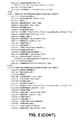
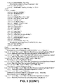
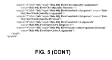
- Figure 5 illustrates a graph structure 110 generated by the flow extractor 102 for the example of Figure 4 .
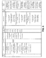
- Figure 6 illustrates one of four test paths generated by the flow analyzer 114 for the example of Figure 4 .
- the flow analyzer 114 may respectively determine the type of each of the workflow building blocks 106 (e.g., the presence of a SLA, router, ticket, etc., in each of the workflow building blocks 106).
- the block at 400 may include a SLA (or be designated as a SLA).
- the SLA tab may include the test scripts for SLA.
- the "pySLA" tag may indicate whether a SLA is present, and a name of the SLA file.
- the SLA processor 222 may process the SLA file (i.e., WorkSLA.xml).
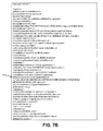
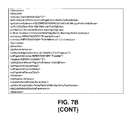
- Figure 7B illustrates an example of a SLA file.
- service level standard goal tags are identified at 704, 706, and 708.
- the SLA processor 222 may process all of the data related to the SLA, where the processed data may be written to a graph format (e.g., "output ⁇ StartXYZCorporationPegaDemo_SLA_filename.xml").
- the graph file may be parsed, for example, by using a Gremlin framework.
- the data may be converted into a natural language, for example, by using a velocity template (e.g., "TemplateRepository ⁇ sla").
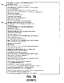
- Figures 7C and 7D respectively illustrate test scripts and a template for the SLA.
- the router tab may include the test scripts for router.
- the flow analyzer 114 may determine whether a router is present, for example, by executing the Xpath of Figure 8A against the input XML (i.e., the extracted workflow XML 200).
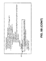
- the "pylmplementation" tag indicates where it is routed to, and at 802, "checkAvailablity” indicates whether it is routed to as a secondary operator if the primary operator is not available.
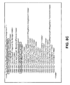
- FIG. 8C illustrates a GraphML node with router data.
- the data may be converted into a natural language, for example, by using a velocity template (e.g., "TemplateRepository ⁇ router").
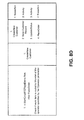
- Figures 8D and 8E respectively illustrate test scripts and a template for the router.
- the flow analyzer 114 may determine whether a ticket is present.
- the flow analyzer 114 may parse the XML, and identify all the activity defined in the block (e.g., "/pagedata/pyLocalActionActivity[text()]").
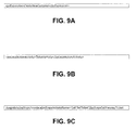
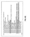
- the flow analyzer 114 may process the activity XML, and check for rule name 'SetTicket'. Referring to Figure 9C , the flow analyzer 114 may get the ticket name (i.e., TestTicket). With respect to catching of a ticket that is thrown, the flow analyzer 114 may check for the block which catches the ticket that is thrown (e.g., with respect to Figure 9C ). All of the information related to tickets may be written in a graph format (e.g., "StartXYZCorporationPegaDemo_Ticket_filename.xml"). Referring to Figure 9D , a sample graph node including ticket data is illustrated. Further, at block 230, the data may be converted into a natural language, for example, by using a velocity template (e.g., "TemplateRepository ⁇ ticketTemplates").
- a velocity template e.g., "TemplateRepository ⁇ ticketTemplates”
- Figure 10 illustrates pseudo-code for a template related to a workflow building block including an assignment, according to an example of the present disclosure.
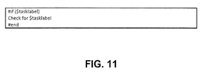
- Figure 11 illustrates pseudo-code for a template related to a workflow building block including a utility, according to an example of the present disclosure.
- Figure 12 illustrates a test artifact for the workflow of Figure 4 , according to an example of the present disclosure.
- the test artifact 134 for the workflow of Figure 4 may include unit test case information at 1200, use-case identification at 1202, rules that are executed for the test artifact 134 at 1204, rule types at 1206, pre-conditions at 1208, steps that are to be executed for the test artifact 134 at 1210, inputs/test data at 1212, and expected results for the corresponding unit test cases and steps to execute at 1214.
- the elements of the system 100 may be used with different workflow management systems, and with different sets of preconfigured building blocks or industry packs.
- the elements of the system 100 may be configured for different uses by providing as inputs different test case templates and different workflow management system building block attributes.
- the system 100 may extensible to accommodate new workflow building blocks and/or changes to semantics and/or attributes of existing workflow building blocks.
- the elements of the system 100 described herein may be machine readable instructions stored on a non-transitory computer readable medium.
- the elements of the workflow test case generation system 100 may be hardware or a combination of machine readable instructions and hardware.
- FIGS 13 and 14 illustrate flowcharts of methods 1300 and 1400 for workflow test case generation, according to examples.
- the methods 1300 and 1400 may be implemented on the workflow test case generation system 100 described above with reference to Figures 1-12 by way of example and not limitation.
- the methods 1300 and 1400 may be practiced in other systems.
- the method 1300 may include receiving an intermediate output of a workflow 104.
- the intermediate output of the workflow 104 may reference a plurality of workflow building blocks 106 that provide a specified functionality at each step of the workflow 104.
- the method 1300 may include analyzing workflow definitions of the intermediate output of the workflow 104 to generate a graph structure 110 that represents the workflow 104.
- the method 1300 may include receiving building block attributes 116, where the building block attributes 116 may include an identification of attributes for the plurality of workflow building blocks 106.
- the method 1300 may include analyzing the building block attributes 116 and the graph structure 110 that represents the workflow 104 to generate building block and attribute information 124 for the workflow 104.
- the method 1300 may include analyzing the building block and attribute information 124 and the graph structure 110 that represents the workflow 104 to generate test paths 126 for the workflow 104, where the test paths 126 may represent paths and/or lateral branches of the workflow 104.
- the method 1300 may include analyzing the building block and attribute information 124, the test paths 126, and a plurality of test case templates 130 to generate test artifacts 134 that include testing to be performed for the workflow 104.
- the intermediate output of the workflow 104 may include an XML schema format.
- the intermediate output of the workflow 104 may include a XML file that represents a single workflow building block of the plurality of workflow building blocks 106, or the plurality of workflow building blocks 106.
- a workflow building block of the plurality of workflow building blocks 106 may include a SLA, a router, a ticket, an assignment, a utility, or an activity.
- test case templates 130 may be associated with building blocks or sets of building blocks, where the test case templates 130 define tests that are to be performed for the associated building blocks or the sets of building blocks.
- the method 1300 may include analyzing the building block and attribute information 124, the test paths 126, and a plurality of test case templates 130 to generate test artifacts 134 that include testing to be performed for the workflow 104 by using the test case templates 130 to extract properties of each workflow building block of the plurality of workflow building blocks 106, and applying heuristics to generate the test artifacts 134.
- the method 1300 may include applying the test artifacts 134 to the workflow 104, and analyzing the application of the test artifacts 134 to the workflow 104 to determine a compliance of the workflow 104 with a predetermined set of compliance requirements.
- the method 1300 may include modifying the workflow 104 in response to a determination that the workflow 104 is not in compliance with at least one of the predetermined set of compliance requirements.
- the method 1300 may include generating the graph structure 110 that represents the workflow 104 by identifying start node and end node details from the intermediate output of the workflow 104.
- the method 1300 may include generating the graph structure 110 that represents the workflow 104 by merging main and sub-flows of the intermediate output of the workflow 104.
- the method 1400 may include receiving, by a flow extractor 102 that is executed by at least one hardware processor (e.g., the hardware processor 1502), an intermediate output of a workflow 104.
- the intermediate output of the workflow 104 may reference a plurality of workflow building blocks 106 that provide a specified functionality at each step of the workflow 104.
- the method 1400 may include analyzing, by the flow extractor 102, workflow definitions of the intermediate output of the workflow 104 to generate a graph structure 110 that represents the workflow 104.
- the method 1400 may include receiving, by a flow analyzer 114 that is executed by the at least one hardware processor, building block attributes 116, where the building block attributes 116 may include an identification of attributes for the plurality of workflow building blocks 106.
- the method 1400 may include analyzing, by the flow analyzer 114, the building block attributes 116 and the graph structure 110 that represents the workflow to generate building block and attribute information 124 for the workflow 104.
- the method 1400 may include analyzing, by the flow analyzer 114, the building block and attribute information 124 and the graph structure 110 that represents the workflow 104 to generate test paths 126 for the workflow 104, where the test paths 126 may represent paths and/or lateral branches of the workflow 104.
- the method 1400 may include analyzing, by a test artifact generator 128 that is executed by the at least one hardware processor, the building block and attribute information 124, the test paths 126, and a plurality of test case templates 130 to generate test artifacts 134 that include testing to be performed for the workflow 104.
- the method 1400 may include applying, by a test artifact applicator 136 that is executed by the at least one hardware processor, the test artifacts 134 to the workflow 104.
- the method 1400 may include analyzing, by a workflow modifier 138 that is executed by the at least one hardware processor, the application of the test artifacts 134 to the workflow 104 to determine a compliance of the workflow 104 with a predetermined set of compliance requirements.
- analyzing, by the flow analyzer 114, the building block attributes 116 and the graph structure 110 that represents the workflow 104 to generate the building block and attribute information 124 for the workflow 104 may further include analyzing, by the flow analyzer 114, the building block attributes 116 by using test scripts that are specific to a type of the workflow building block of the workflow building blocks 106 and the graph structure 110 that represents the workflow 104 to generate the building block and attribute information 124 for the workflow 104.
- analyzing, by the test artifact generator 128, the building block and attribute information 124, the test paths 126, and the plurality of test case templates 130 to generate the test artifacts 134 that include testing to be performed for the workflow 104 may further include using natural language processing to generate the test artifacts 134 in a human readable format.
- a method for workflow test case generation may include determining an output of a workflow 104, where the output of the workflow 104 may reference a plurality of workflow building blocks 106 that provide a specified functionality at each step of the workflow 104.
- the method for workflow test case generation may further include generating a graph structure 110 that represents the workflow 104 based on an analysis of workflow definitions of the output of the workflow 104, and analyzing building block attributes 116 and the graph structure 110 that represents the workflow 104 to generate building block and attribute information 124 for the workflow 104, where the building block attributes 116 may include an identification of attributes for the plurality of workflow building blocks 106.
- the method for workflow test case generation may further include generating test paths 126 for the workflow 104 based on an analysis of the building block and attribute information 124 and the graph structure 110 that represents the workflow 104, where the test paths 126 may represent paths and/or lateral branches of the workflow 104.
- the method for workflow test case generation may further include generating test artifacts 134 that include testing to be performed for the workflow 104 based on an analysis of the building block and attribute information 124, the test paths 126, and a plurality of test case templates 130.
- the method for workflow test case generation may further include analyzing an application of the test artifacts 134 to the workflow 104 to determine a compliance of the workflow 104 with a predetermined set of compliance requirements, and modifying the workflow 104 in response to a determination that the workflow 104 is not in compliance with at least one of the predetermined set of compliance requirements.
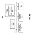
- Figure 15 shows a computer system 1500 that may be used with the examples described herein.
- the computer system may represent a generic platform that includes components that may be in a server or another computer system.
- the computer system 1500 may be used as a platform for the system 100.
- the computer system 1500 may execute, by a processor (e.g., a single or multiple processors) or other hardware processing circuit, the methods, functions and other processes described herein.
- a processor e.g., a single or multiple processors
- a computer readable medium which may be non-transitory, such as hardware storage devices (e.g., RAM (random access memory), ROM (read only memory), EPROM (erasable, programmable ROM), EEPROM (electrically erasable, programmable ROM), hard drives, and flash memory).
- RAM random access memory
- ROM read only memory
- EPROM erasable, programmable ROM
- EEPROM electrically erasable, programmable ROM
- hard drives e.g., hard drives, and flash memory
- the computer system 1500 may include a processor 1502 that may implement or execute machine readable instructions performing some or all of the methods, functions and other processes described herein. Commands and data from the processor 1502 may be communicated over a communication bus 1504.
- the computer system may also include a main memory 1506, such as a random access memory (RAM), where the machine readable instructions and data for the processor 1502 may reside during runtime, and a secondary data storage 1508, which may be non-volatile and stores machine readable instructions and data.
- the memory and data storage are examples of computer readable mediums.
- the memory 1506 may include a workflow test case generator 1520 including machine readable instructions residing in the memory 1506 during runtime and executed by the processor 1502.
- the workflow test case generator 1520 may include the elements of the system 100 shown in Figure 1 .
- the computer system 1500 may include an I/O device 1510, such as a keyboard, a mouse, a display, etc.
- the computer system may include a network interface 1512 for connecting to a network.
- Other known electronic components may be added or substituted in the computer system.
Landscapes
- Business, Economics & Management (AREA)
- Human Resources & Organizations (AREA)
- Engineering & Computer Science (AREA)
- Strategic Management (AREA)
- Entrepreneurship & Innovation (AREA)
- Economics (AREA)
- Operations Research (AREA)
- Game Theory and Decision Science (AREA)
- Development Economics (AREA)
- Marketing (AREA)
- Educational Administration (AREA)
- Quality & Reliability (AREA)
- Tourism & Hospitality (AREA)
- Physics & Mathematics (AREA)
- General Business, Economics & Management (AREA)
- General Physics & Mathematics (AREA)
- Theoretical Computer Science (AREA)
- Management, Administration, Business Operations System, And Electronic Commerce (AREA)
- Debugging And Monitoring (AREA)
Abstract
Description
- This application claims priority to Indian Provisional Patent Application Number:
2779/CHE/2014, filed June 6, 2014 - A workflow may include a plurality of steps needed to complete a task. For example, a workflow may include an orchestrated and repeatable pattern of activity provided by the systematic organization of resources that transform materials, provide services, and/or process information. Workflow management may include management of each step of a workflow, for example, for compliance with workflow requirements, quality standards, etc.
- Features of the present disclosure are illustrated by way of examples shown in the following figures. In the following figures, like numerals indicate like elements, in which:
-
Figure 1 illustrates a detailed architecture of a workflow test case generation system, according to an example of the present disclosure; -
Figure 2 illustrates a logic flow of the workflow test case generation system ofFigure 1 , according to an example of the present disclosure; -
Figures 3A-3G illustrate details of pseudo-code related to the logic flow of the workflow test case generation system ofFigure 1 , according to an example of the present disclosure; -
Figure 4 illustrates a workflow, according to an example of the present disclosure; -
Figure 5 illustrates a graph structure for the workflow ofFigure 4 , according to an example of the present disclosure; -
Figure 6 illustrates a test path for the workflow ofFigure 4 , according to an example of the present disclosure; -
Figures 7A-7D illustrate pseudo-code related to a workflow building block including a service level agreement (SLA), according to an example of the present disclosure; -
Figures 8A-8E illustrate pseudo-code related to a workflow building block including a router, according to an example of the present disclosure; -
Figures 9A-9D illustrate pseudo-code related to a workflow building block including a ticket, according to an example of the present disclosure; -
Figure 10 illustrates pseudo-code related to a workflow building block including an assignment, according to an example of the present disclosure; -
Figure 11 illustrates pseudo-code related to a workflow building block including a utility, according to an example of the present disclosure; -
Figure 12 illustrates a test artifact for the workflow ofFigure 4 , according to an example of the present disclosure -
Figure 13 illustrates a method for workflow test case generation, according to an example of the present disclosure; -
Figure 14 illustrates further details of the method for workflow test case generation, according to an example of the present disclosure; and -
Figure 15 illustrates a computer system, according to an example of the present disclosure. - For simplicity and illustrative purposes, the present disclosure is described by referring mainly to examples thereof. In the following description, numerous specific details are set forth in order to provide a thorough understanding of the present disclosure. It will be readily apparent however, that the present disclosure may be practiced without limitation to these specific details. In other instances, some methods and structures have not been described in detail so as not to unnecessarily obscure the present disclosure.
- Throughout the present disclosure, the terms "a" and "an" are intended to denote at least one of a particular element. As used herein, the term "includes" means includes but not limited to, the term "including" means including but not limited to. The term "based on" means based at least in part on.
- Workflow management may include the visual definition of workflows as building blocks, where the code-behind the building blocks is not visible. For example, workflow management tools may include a user interface that supports drag and drop creation of a workflow which may be described as placing workflow building blocks on a canvas and connecting the workflow building blocks with arrows. The visually created workflows may then be interpreted and automatically implemented by a workflow implementation tool for a workflow management system that uses the workflow. The workflow implementation tool may implement the backend code that is needed for deployment of a workflow. In this manner, workflows may be created and implemented without the need to write code.
- Examples of workflows that may be created and implemented include e-commerce systems such as catalog management systems, shopping carts, order submission systems, etc. For example, a shopping cart may include a workflow, such as add to cart, remove from cart, etc., that may be defined and implemented through the workflow implementation tool. The workflow implementation too! may also include pre-configured workflow building blocks that may be used to create a workflow.
- With respect to implementation of such workflows, a quality assurance testing process is needed to determine whether a workflow meets a desired functional and/or design specification. Based on the complexities associated with such workflows, it can be challenging to objectively and efficiently test such workflows.
- In order to address the aforementioned aspects related to testing of workflows, a workflow test case generation system and a method for workflow test case generation are disclosed herein. The system and method disclosed herein may provide for the analysis of complex workflows, application of semantics of different workflow building blocks used in a workflow definition, and use of templates to generate a comprehensive set of test artifacts that include test cases for the associated workflow. The test artifacts may be leveraged for high-quality testing of complex workflows, thereby reducing defects and cost of rework related to such workflows.
- With respect to analysis of complex workflows, the system and method disclosed herein may provide for the application of test scenarios related to the test artifacts by a test artifact applicator, with the results of the testing being logged and analyzed for compliance by a workflow modifier. Based on the logging and analysis of the testing, the workflow modifier may modify the workflow under consideration for compliance with requirements and/or quality metrics associated with the workflow under consideration.
- The workflow test case generation system and the method for workflow test case generation disclosed herein provide a technical solution to technical problems related, for example, to workflow testing. The system and method disclosed herein provide the technical solution of receiving, by a flow extractor that is executed by at least one hardware processor, an intermediate output of a workflow. The intermediate output of the workflow may reference a plurality of workflow building blocks that provide a specified functionality at each step of the workflow. The system and method disclosed herein may further include analyzing, by the flow extractor, workflow definitions of the intermediate output of the workflow to generate a graph structure that represents the workflow. The system and method disclosed herein may further include receiving, by a flow analyzer that is executed by the at least one hardware processor, building block attributes. The building block attributes may include an identification of attributes for the plurality of workflow building blocks. The system and method disclosed herein may further include analyzing, by the flow analyzer, the building block attributes and the graph structure that represents the workflow to generate building block and attribute information for the workflow. The system and method disclosed herein may further include analyzing, by the flow analyzer, the building block and attribute information and the graph structure that represents the workflow to generate test paths for the workflow. The test paths may represent paths and/or lateral branches of the workflow. The system and method disclosed herein may further include analyzing, by a test artifact generator that is executed by the at least one hardware processor, the building block and attribute information, the test paths, and a plurality of test case templates to generate test artifacts that include testing to be performed for the workflows. The system and method disclosed herein may further include applying, by a test artifact applicator that is executed by the at least one hardware processor, the test artifacts to the workflow, and analyzing, by a workflow modifier that is executed by the at least one hardware processor, the application of the test artifacts to the workflow to determine a compliance of the workflow with a predetermined set of compliance requirements. The system and method disclosed herein may further include modifying, by the workflow modifier, the workflow in response to a determination that the workflow is not in compliance with at least one of the predetermined set of compliance requirements.
-
Figure 1 illustrates a detailed architecture of a workflow testcase generation system 100, according to an example of the present disclosure. Referring toFigure 1 , thesystem 100 is depicted as including aflow extractor 102 to receive an intermediate output of aworkflow 104, for example, in an XML schema format. An intermediate output of theworkflow 104 may be described as an XML representation of theworkflow 104 based on a workflow management system (e.g., aworkflow management system 108 as described herein). Each workflow management system may include a different XML schema format. The output of theworkflow 104 may be provided in one or more XML files that reference variousworkflow building blocks 106 that, within theworkflow management system 108, provide the desired functionality at each step of theworkflow 104. Each XML file may represent a single workflow building block or a plurality of workflow building blocks. The XML files may also specify the flow and/or relationship between and/or within the various workflow building blocks 106. The XML files may be designated as XML definition files, and include workflow definitions extracted from theworkflow management system 108 that implements theworkflow 104. A workflow definition may represent elements such as a sequence between workflow building blocks, a logic related to theworkflow 104, service level agreements (SLAs), routing, etc. - The
flow extractor 102 may analyze the workflow definitions of the XML definition files to generate agraph structure 110. Thegraph structure 110 may represent theworkflow 104. Further, thegraph structure 110 may be stored in agraph structure repository 112. Thegraph structure 110 may use a node and edge format where each node is a workflow building block, and each edge represents the flow between the workflow building block based, for example, on logic and routing. According to an example, thegraph structure 110 may be directed, and may not be annotated with additional information. - A
flow analyzer 114 may receive building block attributes 116, for example, from a buildingblock attribute repository 118. The building block attributes 116 may characterize a building block. For example, a building block denoted flow action may include attributes such as name, assigned use case, routing details, SLA, etc. The building block attributes 116 may provide for the identification of attributes for various pre-defined building blocks (e.g., pre-defined building blocks that are used to generate the workflow 104) provided by a workflow management tool. For example, the pre-defined building blocks may include SLA, router, ticket, assignment, utility, activity, etc., types of building blocks. In this regard, each of the pre-defined building blocks may represent a unique semantic. Each unique semantic may be used to process the building block and its attributes for generation of test artifacts as described herein. For example, an assignment may create an assignment task associated with a work object in a workbasket or worklist. The task may be completed by a person or a system (e.g., the workflow management system 108) before theworkflow 104 can progress further. The assignment may represent a pause or a potential pause in theworkflow 104. A ticket may mark an exception that may arise in theworkflow 104, such as a cancellation. A utility may specify an activity to run at a given point in theworkflow 104 to perform automated processing without any user assignment. The pre-defined building blocks may include various non-workflow concepts such as packaging and inheritances. Packaging may be used to group functionally cohesive flows in theworkflow 104. Inheritance may provide for reuse of common flows across a workflow application. According to an example, the building block attributes 116 may be determined by a subject matter expert (SME) 120 based on an understanding of features and associated XML representations of the workflow building blocks 106. TheSME 120 may input the building block attributes 116 using auser interface 122. As different industry packages, including their associated building blocks, are installed and used within theworkflow management system 108, different building block attributes may be created and made available in the buildingblock attribute repository 118. - The
flow analyzer 114 may reference the building block attributes 116 and thegraph structure 110, to generate building block and attributeinformation 124 for theworkflow 104 under test. Theflow analyzer 114 may reference the building block and attributeinformation 124 and thegraph structure 110 to generatetest paths 126 for theworkflow 104 under test. A test path may be described as one path in thegraph structure 110, and represent a unique flow that may be taken in theworkflow 104 based on the logic of theworkflow 104. Thetest paths 126 may represent paths and/or lateral branches in theworkflow 104. Branches may represent multiple paths emanating from a node (representing a workflow building block). - A
test artifact generator 128 may receive test case templates 130 from a testcase template repository 132. The test case templates 130 may be associated with building blocks or sets of building blocks, and define tests that are to be performed for associated building blocks or sets of building blocks (e.g., the workflow building blocks 106). According to an example, the test case templates may specify tests that are to be performed for individual building blocks. According to another example, the test case templates may specify tests that are to be performed for sets or sequences of building blocks within a flow (e.g., the workflow 104). According to an example, the test case templates 130 may be generated by theSME 120 based, for example, on an understanding of the features and associated functionality of the building blocks that are being used in theworkflow 104. As different industry packages, including their associated building blocks, are installed and used within theworkflow management system 108, different test case templates may be generated and made available in the testcase template repository 132. - The
test artifact generator 128 may analyze the building block and attribute information, thetest paths 126, and the test case templates 130 to generate test artifacts 134 (including test cases) for theworkflow 104 under test. Thetest artifacts 134 may represent documents detailing test scenarios of theworkflow 104. In this regard, thetest artifact generator 128 may use the test case templates 130 to extract properties of each workflow building block in theworkflow 104, and apply heuristics for generating thetest artifacts 134. With respect to the application of heuristics for generating thetest artifacts 134, heuristics may include identifying the building blocks and associated attributes, and populating the block specific natural language templates based on this extracted data. Thetest artifact generator 128 may output and/or store thetest artifacts 134 in a human readable format (e.g., a textual format), such as in a spreadsheet or word processor document. Thetest artifact generator 128 may also analyze the semantics of theworkflow building blocks 106 to alter thetest artifacts 134, and provide contextual information with respect to thetest artifacts 134. - A
test artifact applicator 136 may apply the test artifacts to theworkflow 104 of theworkflow management system 108, with the results of the testing being logged and analyzed for compliance by aworkflow modifier 138. The application of the test artifacts to theworkflow 104 may provide for end to end traceability between requirements for theworkflow management system 108 and thetest artifacts 134. - Based on the logging and analysis of the testing, and the end to end traceability between requirements for the
workflow management system 108 and thetest artifacts 134, theworkflow modifier 138 may modify theworkflow 104 for compliance with the requirements. -
Figure 2 illustrates logic flow of thesystem 100, according to an example of the present disclosure. - Referring to
Figure 2 , theflow extractor 102 may receive an extracted intermediate output (i.e., an extracted workflow XML 200) of theworkflow 104, for example, in an XML schema format. The extractedworkflow XML 200 may be received from an application flow XML repository 202, or otherwise extracted from theworkflow 104. In this regard, the extracted intermediate output of theworkflow 104 may include the flow information of the associated application orworkflow management system 108, the name of the main flow and/or start flow, and the application name. - At
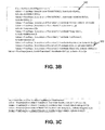
block 204, theflow extractor 102 may identify a start flow name to generate a flow atblock 206. In this regard, the extractedworkflow XML 200 and the start flow information may be passed to theflow extractor 102, where theflow extractor 102 may reconstruct the flow by parsing the XML. For example, referring toFigures 3A and3B , theflow extractor 102 may identify the start node and end node details from the XML using Xpath, where a "pyStartActivity" tag may include the start node detail (e.g., "Start51" at 300) and a "pyEndingActivities" tag may include the end node detail (e.g., "End52" at 302). The node value may be used to obtain the next node detail, where the start node information may be provided to the Xpath "/pagedata/pyModelProcess/pyConnectors/rowdata[pyFrom='Start51']", which may return the output ofFigure 3A . The process of using the node value to obtain the next node detail may be repeated until the end node is reached. Further, the start node value may be replaced with the next node detail. - At
block 208, theflow extractor 102 may determine whether there are any remaining sub flows. - At
block 210, in response to a determination atblock 208 that there are remaining sub flows, theflow extractor 102 may complete flow generation from all sub-flows. - At
block 212, based on the flow generation at block 206 (that includes all sub-flows identified at block 208), the flow generator may merge the flows, and generate thegraph structure 110. The output generated by theflow extractor 102 may include, for example, FromNode and ToNode information. For the example ofFigure 3A ,Figure 3B illustrates a main flow andFigures 3C illustrates a sub-flow. The main flow may be merged with the sub-flow to generate thegraph structure 110 which may include the FromNode and ToNode information. The flow details may be received by theflow analyzer 114, where theflow analyzer 114 may again parse the extractedworkflow XML 200 to fetch the remaining information needed to generate thetest artifacts 134. - At
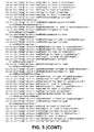
block 214, theflow analyzer 114 may receive thegraph structure 110, and analyze the workflow building blocks 106. In this regard, atblocks flow analyzer 114 may respectively determine the type of each of the workflow building blocks 106 (e.g., the presence of a SLA, router, ticket, etc., in each of the workflow building blocks 106). In this regard, a workflow building block may be referred to as a SLA building block, a router building block, etc., or as a building block that includes a SLA, a router, etc. Referring toFigures 3A-3D ,Figure 3D illustrates an example of pseudo-code for theflow analyzer 114. Referring toFigures 3C and3D , for the sub-flow ofFigure 3C , "TRANSITION54" is of rule type FlowAction, and may be used to fetch all of the information associated with flow action as shown inFigure 3D . - At
blocks flow analyzer 114 may respectively process each of the workflow building blocks 106. For the example ofFigure 2 , theflow analyzer 114 may respectively process the SLA, the router, and the ticket. - At
block 228, theflow analyzer 114 may perform flow consolidation and GraphML processing. The output generated by theflow analyzer 114 may include, for example, TestCase.Graphml. Referring toFigures 3A-3E ,Figures 3E illustrates a TestCase.Graphml. - At
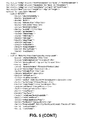
block 230, thetest artifact generator 128 may receive the test case templates 130 from the testcase template repository 132, to generate thetest artifacts 134. In this regard, atblock 230, thetest artifact generator 128 may convert thetest artifacts 134 to natural language steps for testing of theworkflow 104. For example, thetest artifact generator 128 may read the GraphML, and use, for example, a velocity Template application programming interface (API) to describe the flows and constraints in natural language. Thetest artifact generator 128 may read the GraphML by providing the start node and end node details. A different template may be used based on a rule type. For example, referring toFigure 3F , a FlowAction rule type template is illustrated. - At
block 232, thetest artifact generator 128 may use Apache POI API to populate, for example, an XLS (e.g., Excel Spreadsheet) format test artifact, based on input from aformatting repository 234. - With respect to operation of the
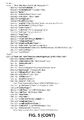
test artifact applicator 136 and theworkflow modifier 138, referring toFigure 3G , from the GraphML, all of the possible paths that may be taken in theworkflow 104 may be identified based on logic, for example, by using a third party API. The start node and end node details which are captured from the XML using the Xpath may also be forwarded to the third party API. From each node of the graph structure 110 (representing the workflow building blocks 106), the type (i.e., ruletype) may be identified as shown inFigure 3G . Referring toFigure 3G , the type (i.e., ruletype) is denoted at 304. Based on the type and section (column names in XLS (i.e., Unit Test Case/Steps to Execute/Expected Result)) the corresponding template may be extracted and loaded, and converted into natural language. For example, if the type is Flowaction and Section is UnittestCase, then the template loaded is \\TemplateRepository\\stFiowTemplates\\ flowActionUnitTestTemplate.vm. -
Figure 4 illustrates a workflow, according to an example of the present disclosure. - Referring to
Figure 4 , atblock 400, a new customer may be created. Atblock 402, the customer record may be saved. At block 404, a status of the customer may be updated. Atblock 406, an order may be placed. Atblock 408, the order related to the order placed at 406 may be saved. Atblock 410, an amount of the order may be checked. At block 412, in response to a determination that the amount of the order is correct, the order may be approved, and the customer status may be updated. Further, at block 414, in response to a determination that the amount of the order is incorrect, the order may be rejected, and the customer status may be updated. - Referring to
Figures 2 ,4 , and5, Figure 5 illustrates agraph structure 110 generated by theflow extractor 102 for the example ofFigure 4 . Further,Figure 6 illustrates one of four test paths generated by theflow analyzer 114 for the example ofFigure 4 . - Referring to
Figures 1 ,2 ,4 , and7A-7D , theflow analyzer 114 may respectively determine the type of each of the workflow building blocks 106 (e.g., the presence of a SLA, router, ticket, etc., in each of the workflow building blocks 106). For example, the block at 400 may include a SLA (or be designated as a SLA). In this regard, with respect to theSLA processor 222, the SLA tab may include the test scripts for SLA. In order to determine (e.g., at block 214) whether a SLA is present or not in theblock 400, the pseudo-code for determining whether a SLA is present or not is illustrated inFigure 7A , for example, at 700 and 702 (e.g., lpagedatalpyTaskInfo/rowdata[@REPEATINGINDEX="{0}/pySLA). The "pySLA" tag may indicate whether a SLA is present, and a name of the SLA file. TheSLA processor 222 may process the SLA file (i.e., WorkSLA.xml).Figure 7B illustrates an example of a SLA file. For the SLA file ofFigure 7B , service level standard goal tags are identified at 704, 706, and 708. Using the same process data related to "Deadline", "passedDeadline" may be retrieved. TheSLA processor 222 may process all of the data related to the SLA, where the processed data may be written to a graph format (e.g., "output\StartXYZCorporationPegaDemo_SLA_filename.xml"). Atblock 228, the graph file may be parsed, for example, by using a Gremlin framework. Further, atblock 230, the data may be converted into a natural language, for example, by using a velocity template (e.g., "TemplateRepository\sla"). In this regard,Figures 7C and 7D respectively illustrate test scripts and a template for the SLA. - Referring to
Figures 1 ,2 ,4 , and8A-8E , with respect to therouter processor 224, the router tab may include the test scripts for router. In this regard, atblock 218, theflow analyzer 114 may determine whether a router is present, for example, by executing the Xpath ofFigure 8A against the input XML (i.e., the extracted workflow XML 200). Referring toFigure 8B , at 800, the "pylmplementation" tag indicates where it is routed to, and at 802, "checkAvailablity" indicates whether it is routed to as a secondary operator if the primary operator is not available. Data related to the router may be extracted, and written into a graph format (e.g., "output\ StartXYZCorporationPegaDemo_FLOW_filename.xml").Figure 8C illustrates a GraphML node with router data. Further, atblock 230, the data may be converted into a natural language, for example, by using a velocity template (e.g., "TemplateRepository\router"). In this regard,Figures 8D and8E respectively illustrate test scripts and a template for the router. - Referring to
Figures 1 ,2 ,4 , and9A-9D , with respect to throwing of a ticket, atblock 220, theflow analyzer 114 may determine whether a ticket is present. Referring toFigure 9A , theflow analyzer 114 may identify the name of the block by using, for example, "/pagedata/pyModelProcess/pyConnectors/rowdata[pyFrom='ASSIGNMENT63'] ". Referring toFigure 9B , theflow analyzer 114 may parse the XML, and identify all the activity defined in the block (e.g., "/pagedata/pyLocalActionActivity[text()]"). Theflow analyzer 114 may process the activity XML, and check for rule name 'SetTicket'. Referring toFigure 9C , theflow analyzer 114 may get the ticket name (i.e., TestTicket). With respect to catching of a ticket that is thrown, theflow analyzer 114 may check for the block which catches the ticket that is thrown (e.g., with respect toFigure 9C ). All of the information related to tickets may be written in a graph format (e.g., "StartXYZCorporationPegaDemo_Ticket_filename.xml"). Referring toFigure 9D , a sample graph node including ticket data is illustrated. Further, atblock 230, the data may be converted into a natural language, for example, by using a velocity template (e.g., "TemplateRepository\ticketTemplates"). - According to further examples of building blocks and related templates,
Figure 10 illustrates pseudo-code for a template related to a workflow building block including an assignment, according to an example of the present disclosure. Further,Figure 11 illustrates pseudo-code for a template related to a workflow building block including a utility, according to an example of the present disclosure. -
Figure 12 illustrates a test artifact for the workflow ofFigure 4 , according to an example of the present disclosure. - Referring to
Figure 12 , thetest artifact 134 for the workflow ofFigure 4 may include unit test case information at 1200, use-case identification at 1202, rules that are executed for thetest artifact 134 at 1204, rule types at 1206, pre-conditions at 1208, steps that are to be executed for thetest artifact 134 at 1210, inputs/test data at 1212, and expected results for the corresponding unit test cases and steps to execute at 1214. - The elements of the
system 100 may be used with different workflow management systems, and with different sets of preconfigured building blocks or industry packs. The elements of thesystem 100 may be configured for different uses by providing as inputs different test case templates and different workflow management system building block attributes. Thus, thesystem 100 may extensible to accommodate new workflow building blocks and/or changes to semantics and/or attributes of existing workflow building blocks. - The elements of the
system 100 described herein may be machine readable instructions stored on a non-transitory computer readable medium. In addition, or alternatively, the elements of the workflow testcase generation system 100 may be hardware or a combination of machine readable instructions and hardware. -
Figures 13 and14 illustrate flowcharts ofmethods methods case generation system 100 described above with reference toFigures 1-12 by way of example and not limitation. Themethods - Referring to
Figure 1 and13 , atblock 1302, themethod 1300 may include receiving an intermediate output of aworkflow 104. The intermediate output of theworkflow 104 may reference a plurality ofworkflow building blocks 106 that provide a specified functionality at each step of theworkflow 104. - At
block 1304, themethod 1300 may include analyzing workflow definitions of the intermediate output of theworkflow 104 to generate agraph structure 110 that represents theworkflow 104. - At
block 1306, themethod 1300 may include receiving building block attributes 116, where the building block attributes 116 may include an identification of attributes for the plurality of workflow building blocks 106. - At
block 1308, themethod 1300 may include analyzing the building block attributes 116 and thegraph structure 110 that represents theworkflow 104 to generate building block and attributeinformation 124 for theworkflow 104. - At
block 1310, themethod 1300 may include analyzing the building block and attributeinformation 124 and thegraph structure 110 that represents theworkflow 104 to generatetest paths 126 for theworkflow 104, where thetest paths 126 may represent paths and/or lateral branches of theworkflow 104. - At
block 1312, themethod 1300 may include analyzing the building block and attributeinformation 124, thetest paths 126, and a plurality of test case templates 130 to generatetest artifacts 134 that include testing to be performed for theworkflow 104. - According to an example, the intermediate output of the
workflow 104 may include an XML schema format. - According to an example, the intermediate output of the
workflow 104 may include a XML file that represents a single workflow building block of the plurality ofworkflow building blocks 106, or the plurality of workflow building blocks 106. - According to an example, a workflow building block of the plurality of
workflow building blocks 106 may include a SLA, a router, a ticket, an assignment, a utility, or an activity. - According to an example, the test case templates 130 may be associated with building blocks or sets of building blocks, where the test case templates 130 define tests that are to be performed for the associated building blocks or the sets of building blocks.
- According to an example, the
method 1300 may include analyzing the building block and attributeinformation 124, thetest paths 126, and a plurality of test case templates 130 to generatetest artifacts 134 that include testing to be performed for theworkflow 104 by using the test case templates 130 to extract properties of each workflow building block of the plurality ofworkflow building blocks 106, and applying heuristics to generate thetest artifacts 134. - According to an example, the
method 1300 may include applying thetest artifacts 134 to theworkflow 104, and analyzing the application of thetest artifacts 134 to theworkflow 104 to determine a compliance of theworkflow 104 with a predetermined set of compliance requirements. - According to an example, the
method 1300 may include modifying theworkflow 104 in response to a determination that theworkflow 104 is not in compliance with at least one of the predetermined set of compliance requirements. - According to an example, the
method 1300 may include generating thegraph structure 110 that represents theworkflow 104 by identifying start node and end node details from the intermediate output of theworkflow 104. - According to an example, the
method 1300 may include generating thegraph structure 110 that represents theworkflow 104 by merging main and sub-flows of the intermediate output of theworkflow 104. - Referring to
Figure 1 and14 , atblock 1402, themethod 1400 may include receiving, by aflow extractor 102 that is executed by at least one hardware processor (e.g., the hardware processor 1502), an intermediate output of aworkflow 104. The intermediate output of theworkflow 104 may reference a plurality ofworkflow building blocks 106 that provide a specified functionality at each step of theworkflow 104. - At
block 1404, themethod 1400 may include analyzing, by theflow extractor 102, workflow definitions of the intermediate output of theworkflow 104 to generate agraph structure 110 that represents theworkflow 104. - At
block 1406, themethod 1400 may include receiving, by aflow analyzer 114 that is executed by the at least one hardware processor, building block attributes 116, where the building block attributes 116 may include an identification of attributes for the plurality of workflow building blocks 106. - At
block 1408, themethod 1400 may include analyzing, by theflow analyzer 114, the building block attributes 116 and thegraph structure 110 that represents the workflow to generate building block and attributeinformation 124 for theworkflow 104. - At
block 1410, themethod 1400 may include analyzing, by theflow analyzer 114, the building block and attributeinformation 124 and thegraph structure 110 that represents theworkflow 104 to generatetest paths 126 for theworkflow 104, where thetest paths 126 may represent paths and/or lateral branches of theworkflow 104. - At
block 1412, themethod 1400 may include analyzing, by atest artifact generator 128 that is executed by the at least one hardware processor, the building block and attributeinformation 124, thetest paths 126, and a plurality of test case templates 130 to generatetest artifacts 134 that include testing to be performed for theworkflow 104. - At
block 1414, themethod 1400 may include applying, by atest artifact applicator 136 that is executed by the at least one hardware processor, thetest artifacts 134 to theworkflow 104. - At
block 1416, themethod 1400 may include analyzing, by aworkflow modifier 138 that is executed by the at least one hardware processor, the application of thetest artifacts 134 to theworkflow 104 to determine a compliance of theworkflow 104 with a predetermined set of compliance requirements. - According to an example, for the
method 1400, analyzing, by theflow analyzer 114, the building block attributes 116 and thegraph structure 110 that represents theworkflow 104 to generate the building block and attributeinformation 124 for theworkflow 104 may further include analyzing, by theflow analyzer 114, the building block attributes 116 by using test scripts that are specific to a type of the workflow building block of theworkflow building blocks 106 and thegraph structure 110 that represents theworkflow 104 to generate the building block and attributeinformation 124 for theworkflow 104. - According to an example, for the
method 1400, analyzing, by thetest artifact generator 128, the building block and attributeinformation 124, thetest paths 126, and the plurality of test case templates 130 to generate thetest artifacts 134 that include testing to be performed for theworkflow 104, may further include using natural language processing to generate thetest artifacts 134 in a human readable format. - According to an example, a method for workflow test case generation may include determining an output of a
workflow 104, where the output of theworkflow 104 may reference a plurality ofworkflow building blocks 106 that provide a specified functionality at each step of theworkflow 104. The method for workflow test case generation may further include generating agraph structure 110 that represents theworkflow 104 based on an analysis of workflow definitions of the output of theworkflow 104, and analyzing building block attributes 116 and thegraph structure 110 that represents theworkflow 104 to generate building block and attributeinformation 124 for theworkflow 104, where the building block attributes 116 may include an identification of attributes for the plurality of workflow building blocks 106. The method for workflow test case generation may further include generatingtest paths 126 for theworkflow 104 based on an analysis of the building block and attributeinformation 124 and thegraph structure 110 that represents theworkflow 104, where thetest paths 126 may represent paths and/or lateral branches of theworkflow 104. The method for workflow test case generation may further include generatingtest artifacts 134 that include testing to be performed for theworkflow 104 based on an analysis of the building block and attributeinformation 124, thetest paths 126, and a plurality of test case templates 130. The method for workflow test case generation may further include analyzing an application of thetest artifacts 134 to theworkflow 104 to determine a compliance of theworkflow 104 with a predetermined set of compliance requirements, and modifying theworkflow 104 in response to a determination that theworkflow 104 is not in compliance with at least one of the predetermined set of compliance requirements. -
Figure 15 shows acomputer system 1500 that may be used with the examples described herein. The computer system may represent a generic platform that includes components that may be in a server or another computer system. Thecomputer system 1500 may be used as a platform for thesystem 100. Thecomputer system 1500 may execute, by a processor (e.g., a single or multiple processors) or other hardware processing circuit, the methods, functions and other processes described herein. These methods, functions and other processes may be embodied as machine readable instructions stored on a computer readable medium, which may be non-transitory, such as hardware storage devices (e.g., RAM (random access memory), ROM (read only memory), EPROM (erasable, programmable ROM), EEPROM (electrically erasable, programmable ROM), hard drives, and flash memory). - The
computer system 1500 may include aprocessor 1502 that may implement or execute machine readable instructions performing some or all of the methods, functions and other processes described herein. Commands and data from theprocessor 1502 may be communicated over acommunication bus 1504. The computer system may also include amain memory 1506, such as a random access memory (RAM), where the machine readable instructions and data for theprocessor 1502 may reside during runtime, and asecondary data storage 1508, which may be non-volatile and stores machine readable instructions and data. The memory and data storage are examples of computer readable mediums. Thememory 1506 may include a workflowtest case generator 1520 including machine readable instructions residing in thememory 1506 during runtime and executed by theprocessor 1502. The workflowtest case generator 1520 may include the elements of thesystem 100 shown inFigure 1 . - The
computer system 1500 may include an I/O device 1510, such as a keyboard, a mouse, a display, etc. The computer system may include anetwork interface 1512 for connecting to a network. Other known electronic components may be added or substituted in the computer system. - What has been described and illustrated herein is an example along with some of its variations. The terms, descriptions and figures used herein are set forth by way of illustration only and are not meant as limitations. Many variations are possible within the spirit and scope of the subject matter, which is intended to be defined by the following claims -- and their equivalents -- in which all terms are meant in their broadest reasonable sense unless otherwise indicated.
Claims (15)
- A workflow test case generation system comprising:a flow extractor, executed by at least one hardware processor, toreceive an intermediate output of a workflow, wherein the intermediate output of the workflow references a plurality of workflow building blocks that provide a specified functionality at each step of the workflow, andanalyze workflow definitions of the intermediate output of the workflow to generate a graph structure that represents the workflow;a flow analyzer, executed by the at least one hardware processor, toreceive building block attributes, wherein the building block attributes include an identification of attributes for the plurality of workflow building blocks,analyze the building block attributes and the graph structure that represents the workflow to generate building block and attribute information for the workflow, andanalyze the building block and attribute information and the graph structure that represents the workflow to generate test paths for the workflow, wherein the test paths represent at least one of paths and lateral branches of the workflow; anda test artifact generator, executed by the at least one hardware processor, toanalyze the building block and attribute information, the test paths, and a plurality of test case templates to generate test artifacts that include testing to be performed for the workflow.
- The workflow test case generation system according to claim 1, wherein the intermediate output of the workflow includes one or more of the following:an Extensible Markup Language (XML) schema format;an XML file that represents a single workflow building block of the plurality of workflow building blocks, or the plurality of workflow building blocks.
- The workflow test case generation system according to claim 1 or 2, wherein a workflow building block of the plurality of workflow building blocks includes one of a service level agreement (SLA), a router, a ticket, an assignment, a utility, and an activity.
- The workflow test case generation system according to any one of the preceding claims, wherein the test case templates are associated with building blocks or sets of building blocks, and wherein the test case templates define tests that are to be performed for the associated building blocks or the sets of building blocks.
- The workflow test case generation system according to any one of the preceding claims, wherein the test artifact generator is to analyze the building block and attribute information, the test paths, and a plurality of test case templates to generate test artifacts that include testing to be performed for the workflow byusing the test case templates to extract properties of each workflow building block of the plurality of workflow building blocks, andapplying heuristics to generate the test artifacts.
- The workflow test case generation system according to any one of the preceding claims, wherein the test artifact generator is to further output the test artifacts in a human readable format;
wherein the human readable format may be an Excel Spreadsheet (XLS) format. - The workflow test case generation system according to any one of the preceding claims, further comprising:a test artifact applicator, executed by the at least one hardware processor, to apply the test artifacts to the workflow; anda workflow modifier, executed by the at least one hardware processor,to analyze the application of the test artifacts to the workflow to determine a compliance of the workflow with a predetermined set of compliance requirements, and optionally,to further modify the workflow in response to a determination that the workflow is not in compliance with at least one of the predetermined set of compliance requirements.
- The workflow test case generation system according to any one of the preceding claims, wherein the flow extractor is to generate the graph structure that represents the workflow by
identifying start node and end node details from the intermediate output of the workflow; and/or
merging main and sub-flows of the intermediate output of the workflow. - A method for workflow test case generation, the method comprising:receiving, by a flow extractor that is executed by at least one hardware processor, an intermediate output of a workflow, wherein the intermediate output of the workflow references a plurality of workflow building blocks that provide a specified functionality at each step of the workflow;analyzing, by the flow extractor, workflow definitions of the intermediate output of the workflow to generate a graph structure that represents the workflow;receiving, by a flow analyzer that is executed by the at least one hardware processor, building block attributes, wherein the building block attributes include an identification of attributes for the plurality of workflow building blocks;analyzing, by the flow analyzer, the building block attributes and the graph structure that represents the workflow to generate building block and attribute information for the workflow;analyzing, by the flow analyzer, the building block and attribute information and the graph structure that represents the workflow to generate test paths for the workflow, wherein the test paths represent at least one of paths and lateral branches of the workflow;analyzing, by a test artifact generator that is executed by the at least one hardware processor, the building block and attribute information, the test paths, and a plurality of test case templates to generate test artifacts that include testing to be performed for the workflow;applying, by a test artifact applicator that is executed by the at least one hardware processor, the test artifacts to the workflow; andanalyzing, by a workflow modifier that is executed by the at least one hardware processor, the application of the test artifacts to the workflow to determine a compliance of the workflow with a predetermined set of compliance requirements.
- The method for workflow test case generation according to claim 9, wherein analyzing, by the flow analyzer, the building block attributes and the graph structure that represents the workflow to generate the building block and attribute information for the workflow further comprises:analyzing, by the flow analyzer, the building block attributes by using test scripts that are specific to a type of the workflow building block of the workflow building blocks and the graph structure that represents the workflow to generate the building block and attribute information for the workflows.
- The method for workflow test case generation according to claim 9 or 10, wherein analyzing, by the test artifact generator, the building block and attribute information, the test paths, and the plurality of test case templates to generate the test artifacts that include testing to be performed for the workflow, further comprises:using the test case templates to extract properties of each workflow building block of the plurality of workflow building blocks;applying heuristics to generate the test artifacts; and optionallyusing natural language processing to generate the test artifacts in a human readable format.
- The method for workflow test case generation according to any one of claims 9 to 11, further comprising:modifying, by the workflow modifier, the workflow in response to a determination that the workflow is not in compliance with at least one of the predetermined set of compliance requirements.
- A non-transitory computer readable medium having stored thereon machine readable instructions for workflow test case generation, the machine readable instructions when executed cause at least one hardware processor to:determine an output of a workflow, wherein the output of the workflow references a plurality of workflow building blocks that provide a specified functionality at each step of the workflow;generate a graph structure that represents the workflow based on an analysis of workflow definitions of the output of the workflow;analyze building block attributes and the graph structure that represents the workflow to generate building block and attribute information for the workflow, wherein the building block attributes include an identification of attributes for the plurality of workflow building blocks;generate test paths for the workflow based on an analysis of the building block and attribute information and the graph structure that represents the workflow, wherein the test paths represent at least one of paths and lateral branches of the workflow;generate test artifacts that include testing to be performed for the workflow based on an analysis of the building block and attribute information, the test paths, and a plurality of test case templates;analyze an application of the test artifacts to the workflow to determine a compliance of the workflow with a predetermined set of compliance requirements; andmodify the workflow in response to a determination that the workflow is not in compliance with at least one of the predetermined set of compliance requirements.
- The non-transitory computer readable medium according to claim 13, wherein the output of the workflow includes an Extensible Markup Language (XML) schema format.
- The non-transitory computer readable medium according to claim 13 or 14, wherein the machine readable instructions to generate the graph structure that represents the workflow based on the analysis of workflow definitions of the output of the workflow further comprise machine readable instructions to:generate the graph structure that represents the workflow by identifying start node and end node details from the output of the workflow.
Applications Claiming Priority (1)
| Application Number | Priority Date | Filing Date | Title |
|---|---|---|---|
| IN2779CH2014 | 2014-06-06 |
Publications (1)
| Publication Number | Publication Date |
|---|---|
| EP2953072A1 true EP2953072A1 (en) | 2015-12-09 |
Family
ID=53476669
Family Applications (1)
| Application Number | Title | Priority Date | Filing Date |
|---|---|---|---|
| EP15171011.8A Ceased EP2953072A1 (en) | 2014-06-06 | 2015-06-08 | Workflow test case generation |
Country Status (1)
| Country | Link |
|---|---|
| EP (1) | EP2953072A1 (en) |
Cited By (4)
| Publication number | Priority date | Publication date | Assignee | Title |
|---|---|---|---|---|
| CN110109837A (en) * | 2019-05-06 | 2019-08-09 | 上海蔚来汽车有限公司 | Integration test method, device and controller and medium |
| CN111221725A (en) * | 2019-11-27 | 2020-06-02 | 杭州涂鸦信息技术有限公司 | Automatic testing method and system, readable storage medium and computer equipment |
| CN111258881A (en) * | 2019-12-31 | 2020-06-09 | 上海金仕达软件科技有限公司 | An Intelligent Test System for Workflow Test |
| GB2605483A (en) * | 2020-12-30 | 2022-10-05 | Ibm | Automatic creation and execution of a test harness for workflows |
-
2015
- 2015-06-08 EP EP15171011.8A patent/EP2953072A1/en not_active Ceased
Non-Patent Citations (1)
| Title |
|---|
| No relevant documents disclosed * |
Cited By (8)
| Publication number | Priority date | Publication date | Assignee | Title |
|---|---|---|---|---|
| CN110109837A (en) * | 2019-05-06 | 2019-08-09 | 上海蔚来汽车有限公司 | Integration test method, device and controller and medium |
| CN110109837B (en) * | 2019-05-06 | 2023-10-13 | 上海蔚来汽车有限公司 | Integrated test methods, apparatus, and controllers and media |
| CN111221725A (en) * | 2019-11-27 | 2020-06-02 | 杭州涂鸦信息技术有限公司 | Automatic testing method and system, readable storage medium and computer equipment |
| CN111221725B (en) * | 2019-11-27 | 2023-04-07 | 杭州涂鸦信息技术有限公司 | Automatic testing method and system, readable storage medium and computer equipment |
| CN111258881A (en) * | 2019-12-31 | 2020-06-09 | 上海金仕达软件科技有限公司 | An Intelligent Test System for Workflow Test |
| CN111258881B (en) * | 2019-12-31 | 2023-11-28 | 上海金仕达软件科技股份有限公司 | Intelligent test system for workflow test |
| GB2605483A (en) * | 2020-12-30 | 2022-10-05 | Ibm | Automatic creation and execution of a test harness for workflows |
| US12443900B2 (en) | 2020-12-30 | 2025-10-14 | International Business Machines Corporation | Automatic creation and execution of a test harness for workflows |
Also Published As
| Publication number | Publication date |
|---|---|
| AU2015203263A1 (en) | 2015-12-24 |
| AU2015203263B2 (en) | 2016-05-05 |
| AU2015203263A8 (en) | 2016-05-19 |
Similar Documents
| Publication | Publication Date | Title |
|---|---|---|
| US10289524B2 (en) | Workflow test case generation | |
| Bhatia et al. | Ontologies for software engineering: Past, present and future | |
| US20170357927A1 (en) | Process management for documentation-driven solution development and automated testing | |
| US8661404B2 (en) | Method for improving execution efficiency of a software package customization | |
| CN109710528B (en) | Test script generation method, device, equipment and medium | |
| CN112748950B (en) | Software code examination method and device | |
| CN109840192B (en) | Method and device for automatic testing | |
| Sami et al. | AI based multiagent approach for requirements elicitation and analysis | |
| Haakman et al. | AI lifecycle models need to be revised. an exploratory study in fintech | |
| US20130132299A1 (en) | Using non-textual notation for describing service related human experience based on a hierarchal model of human needs | |
| Dragicevic et al. | Method for elicitation, documentation and validation of software user requirements (MEDoV) | |
| US9619463B2 (en) | Document decomposition into parts based upon translation complexity for translation assignment and execution | |
| del Rıo-Ortega et al. | Towards modelling and tracing key performance indicators in business processes | |
| AU2015203263B8 (en) | Workflow test case generation | |
| AU2015203263B2 (en) | Workflow test case generation | |
| Nakagawa et al. | Towards a process to design product line architectures based on reference architectures | |
| US10558981B1 (en) | Methods systems and articles of manufacture for generating tax worksheet application | |
| JP2014519671A5 (en) | ||
| US20170103357A1 (en) | Task-specifying device, task-specifying method, and recording medium | |
| García-Mireles | Addressing product quality characteristics using the ISO/IEC 29110 | |
| US20220365812A1 (en) | Method and system for sustainability measurement | |
| Guo et al. | Api test case generation by extracting http requests during front-end testing | |
| Luburić et al. | Applicability issues in security requirements engineering for agile development | |
| Ali et al. | Improving component based software integration testing using data mining technique | |
| Bobkowska et al. | On efficient collaboration between lawyers and software engineers when transforming legal regulations to law-related requirements |
Legal Events
| Date | Code | Title | Description |
|---|---|---|---|
| PUAI | Public reference made under article 153(3) epc to a published international application that has entered the european phase |
Free format text: ORIGINAL CODE: 0009012 |
|
| AK | Designated contracting states |
Kind code of ref document: A1 Designated state(s): AL AT BE BG CH CY CZ DE DK EE ES FI FR GB GR HR HU IE IS IT LI LT LU LV MC MK MT NL NO PL PT RO RS SE SI SK SM TR |
|
| AX | Request for extension of the european patent |
Extension state: BA ME |
|
| 17P | Request for examination filed |
Effective date: 20160602 |
|
| RBV | Designated contracting states (corrected) |
Designated state(s): AL AT BE BG CH CY CZ DE DK EE ES FI FR GB GR HR HU IE IS IT LI LT LU LV MC MK MT NL NO PL PT RO RS SE SI SK SM TR |
|
| 17Q | First examination report despatched |
Effective date: 20170420 |
|
| 18R | Application refused |
Effective date: 20180911 |