EP2952999B1 - Wearable mobile terminal with improved photo shutter and touch sensor - Google Patents
Wearable mobile terminal with improved photo shutter and touch sensor Download PDFInfo
- Publication number
- EP2952999B1 EP2952999B1 EP14200648.5A EP14200648A EP2952999B1 EP 2952999 B1 EP2952999 B1 EP 2952999B1 EP 14200648 A EP14200648 A EP 14200648A EP 2952999 B1 EP2952999 B1 EP 2952999B1
- Authority
- EP
- European Patent Office
- Prior art keywords
- transparent electrode
- mobile terminal
- transparent
- glass
- user
- Prior art date
- Legal status (The legal status is an assumption and is not a legal conclusion. Google has not performed a legal analysis and makes no representation as to the accuracy of the status listed.)
- Active
Links
Images





Classifications
-
- G—PHYSICS
- G06—COMPUTING OR CALCULATING; COUNTING
- G06F—ELECTRIC DIGITAL DATA PROCESSING
- G06F3/00—Input arrangements for transferring data to be processed into a form capable of being handled by the computer; Output arrangements for transferring data from processing unit to output unit, e.g. interface arrangements
- G06F3/01—Input arrangements or combined input and output arrangements for interaction between user and computer
- G06F3/03—Arrangements for converting the position or the displacement of a member into a coded form
- G06F3/041—Digitisers, e.g. for touch screens or touch pads, characterised by the transducing means
- G06F3/0416—Control or interface arrangements specially adapted for digitisers
- G06F3/04164—Connections between sensors and controllers, e.g. routing lines between electrodes and connection pads
-
- G—PHYSICS
- G02—OPTICS
- G02B—OPTICAL ELEMENTS, SYSTEMS OR APPARATUS
- G02B27/00—Optical systems or apparatus not provided for by any of the groups G02B1/00 - G02B26/00, G02B30/00
- G02B27/01—Head-up displays
- G02B27/017—Head mounted
- G02B27/0172—Head mounted characterised by optical features
-
- G—PHYSICS
- G06—COMPUTING OR CALCULATING; COUNTING
- G06F—ELECTRIC DIGITAL DATA PROCESSING
- G06F1/00—Details not covered by groups G06F3/00 - G06F13/00 and G06F21/00
- G06F1/16—Constructional details or arrangements
- G06F1/1613—Constructional details or arrangements for portable computers
- G06F1/163—Wearable computers, e.g. on a belt
-
- G—PHYSICS
- G06—COMPUTING OR CALCULATING; COUNTING
- G06T—IMAGE DATA PROCESSING OR GENERATION, IN GENERAL
- G06T19/00—Manipulating three-dimensional [3D] models or images for computer graphics
- G06T19/006—Mixed reality
-
- H—ELECTRICITY
- H04—ELECTRIC COMMUNICATION TECHNIQUE
- H04N—PICTORIAL COMMUNICATION, e.g. TELEVISION
- H04N9/00—Details of colour television systems
- H04N9/12—Picture reproducers
- H04N9/31—Projection devices for colour picture display, e.g. using electronic spatial light modulators [ESLM]
- H04N9/3141—Constructional details thereof
-
- G—PHYSICS
- G02—OPTICS
- G02B—OPTICAL ELEMENTS, SYSTEMS OR APPARATUS
- G02B27/00—Optical systems or apparatus not provided for by any of the groups G02B1/00 - G02B26/00, G02B30/00
- G02B27/01—Head-up displays
- G02B27/017—Head mounted
- G02B2027/0178—Eyeglass type
Definitions
- Embodiments of the present disclosure relates to a glass type mobile terminal including a camera and a light transmissive lens, which may acquire and use information easily, while living a daily life.
- Terminals may be generally classified as mobile/portable terminals or stationary terminals according to their mobility. Mobile terminals may also be classified as handheld terminals or vehicle mounted terminals according to whether or not a user can directly carry the terminal.
- Mobile terminals have become increasingly more functional. Examples of such functions include data and voice communications, capturing images and video via a camera, recording audio, playing music files via a speaker system, and displaying images and video on a display. Some mobile terminals include additional functionality which supports game playing, while other terminals are configured as multimedia players. More recently, mobile terminals have been configured to receive broadcast and multicast signals which permit viewing of content such as videos and television programs.
- US5572343 A discloses a head mounted see-through display including a liquid crystal shutter over the display.
- US2013/321462 A1 discloses glasses having a liquid crystal shutter to control attenuation of incident light.
- An object of the present disclosure is to provide a wearable glass type mobile terminal which may enhance visibility of an image focused on a transparent screen provided therein.
- Embodiments of the present disclosure provide a glass type mobile terminal according to clam 1.
- the glass type mobile terminal may further include a touch sensor coupled to the front surface of the light transmissive lens to sense capacity change so as to receive an input touch signal.
- the transparency of the photo shutter may be controlled based on the number of the touches input to the touch sensor.
- the controller may control transparency of a portion of the photo shutter where the touch input is sensed by the touch sensor.
- the controller may control the transparency of the photo shutter to be lowered, when a touch and drag input is sensed by the touch sensor in a first direction, and to be heightened, when a touch and drag input is sensed by the touch sensor in a second direction.
- the photo shutter may include a first transparent glass having a first transparent electrode formed in one surface thereof; a second transparent glass having a second transparent electrode formed in the other surface thereof, with spaced apart from one surface of the first electrode layer; a liquid crystal layer having liquid crystals filled between the first and second transparent glasses; a first polarizing plate coupled to the first transparent glass to arrange lights in one direction; and a second polarizing plate coupled to the second transparent glass to arrange lights in a vertical direction with respect to the first polarizing plate.
- the glass type mobile terminal may further include a third transparent electrode formed in an opposite surface of a surface where the second transparent electrode of the second transparent glass is formed or the first polarizing plate, wherein the controller determines presence of a touch input by sensing capacity change between the first transparent electrode and the second transparent electrode.
- the controller may control arrangement of liquid crystals by applying a signal to the first transparent electrode and the second transparent electrode at preset intervals, and determine presence of a touch input by sensing capacity change between the first transparent electrode and the second transparent electrode, when the first transparent electrode and the second transparent electrode are not used for control of the liquid crystal arrangement.
- the photo shutter may include PDLC (Polymer Dispersed Liquid Crystal).
- the glass type mobile terminal may further include a proximity illumination sensor for sensing light nearby, wherein the controller controls the transparency of the photo shutter based on illumination sensed by the proximity illumination sensor.
- a control rate of the transparency when the illumination is high may be higher than a control rate of the transparency when the illumination is low.
- the photo shutter selectively may control transparency possessed by each of divided portions.
- the controller may control the photo shutter to lower transparency of a text portion of the image than transparency of the other portion.
- the glass type mobile terminal may further include a video output unit for providing an image from a lateral surface of the light transmissive lens.
- the transparent screen is tilted to transmit an image incident from the lateral surface of the light transmissive lens.
- the glass type mobile terminal may further include an acceleration sensor, wherein the controller heightens transparency of the photo shutter, when the acceleration sensor senses movement for a preset time or more in a state of lowering the transparency of the photo sensor, and the controller lowers the transparency of the photo shutter again, when the acceleration sensor does not sense the movement in a preset time or more.
- the glass type mobile terminal may further include a touch pad coupled to the band frame to be located in the user's side, wherein the controller controls the image to have a pointer moving in response to the touch input, when the user's touch input to the touch pad is sensed.
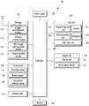
- FIG. 1 is a block diagram of a mobile terminal in accordance with the present disclosure.
- the glass type mobile terminal 100 is shown having wireless communication unit 110 configured with several commonly implemented components.
- the wireless communication unit 110 typically includes one or more components which permit wireless communication between the glass type mobile terminal 100 and a wireless communication system or network within which the mobile terminal is located.
- the wireless communication unit 110 typically includes one or more components which permits wireless communication between the glass type mobile terminal 100 and a wireless communication system or network within which the mobile terminal 100 is located.
- the wireless communication unit 110 can include a mobile communication module 112, a wireless internet module 113, a short-range communication module 114, a position-location module 115 and the like.
- the mobile communication module 112 transmits/receives wireless signals to/from one or more network entities (e.g., base station, external terminal, server, etc.) via a mobile network such as GSM(Gobal System for Mobile communications), CDMA(Code Division Multiple Access), WCDMA(Wideband CDMA) and so on.
- a mobile network such as GSM(Gobal System for Mobile communications), CDMA(Code Division Multiple Access), WCDMA(Wideband CDMA) and so on.
- GSM Gobal System for Mobile communications
- CDMA Code Division Multiple Access
- WCDMA Wideband CDMA
- the wireless internet module 113 supports Internet access for the mobile terminal 100.
- This module may be internally or externally coupled to the mobile terminal 100.
- the wireless Internet technology can include WLAN(Wireless LAN) (Wi-Fi), Wibro (Wireless broadband), Wimax (World Interoperability for Microwave Access), HSDPA(High Speed Downlink Packet Access), GSM, CDMA, WCDMA, LTE (Long Term Evolution) etc.
- Wireless internet access by Wibro, HSPDA, GSM, CDMA, WCDMA, LTE or the like is achieved via a mobile communication network.
- the wireless internet module 113 configured to perform the wireless internet access via the mobile communication network can be understood as a sort of the mobile communication module 112.
- the short-range communication module 114 facilitates relatively short-range communications. Suitable technologies for implementing this module include radio frequency identification (RFID), infrared data association (IrDA), ultra-wideband (UWB), as well at the networking technologies commonly referred to as Bluetooth and ZigBee, to name a few.
- RFID radio frequency identification
- IrDA infrared data association
- UWB ultra-wideband
- the position-location module 115 identifies or otherwise obtains the location of the mobile terminal 100. If desired, this module may be implemented with a global positioning system (GPS) module. According to the current technology, the GPS module 115 is able to precisely calculate current 3-dimensional position information based on at least one of longitude, latitude and altitude and direction (or orientation) by calculating distance information and precise time information from at least three satellites and then applying triangulation to the calculated information. Currently, location and time information are calculated using three satellites, and errors of the calculated location position and time information are then amended using another satellite. Besides, the GPS module 115 is able to calculate speed information by continuously calculating a real-time current location.
- GPS global positioning system
- the input unit 120 may be configured to provide audio or video signal input to the mobile terminal 100.
- the A/V input unit 120 includes a camera 121 and a microphone 122.
- the camera 121 receives and processes image frames of still pictures or video, which are obtained by an image sensor in a video call mode or a photographing mode.
- the processed image frames can be displayed on the display 151 of the output unit 150.
- the image frames processed by the camera 121 can be stored in the memory 160 or can be externally transmitted via the wireless communication unit 110.
- at least two cameras 121 can be provided to the glass type mobile terminal 100 according to environment of usage.
- the microphone 122 receives an external audio signal while the portable device is in a particular mode, such as phone call mode, recording mode and voice recognition. This audio signal is processed and converted into electric audio data. The processed audio data is transformed into a format transmittable to a mobile communication base station via the mobile communication module 112 in case of a call mode.
- the microphone 122 typically includes assorted noise removing algorithms to remove noise generated in the course of receiving the external audio signal.
- An image recognition unit 125 is a device configured to extract information from an image photographed by the camera 121 and the image recognition unit 125 may identify the photographed image. In case the photographed image has a character, the image recognition unit converts a character into text data. In case the image has a plurality of objects, the image recognition unit extracts an object which will be compared with information stored in the memory 160.
- the motion picture consists of still images and the image recognition unit 125 acquires information of all the still images and the controller processes the acquired information.
- this process might be unnecessary waste.
- unnecessary information is extracted and provided to a user, it is inconvenient of a user to use a glass type mobile terminal 100 wearable like glasses.
- the user can extract necessary information.
- the camera 121 may photograph the same object for more than a preset time period and information on the object may be extracted.
- the object occupies a large area of the user's view and it can be determined that the user is looking at the corresponding object.
- information on the object may be extracted.
- the image recognition unit 125 may recognize a gesture created by the user and processes the input gesture as a user command. For example, the image recognition unit 125 may recognize a circle drawn by the user as "yes" or perform a function of selecting a character or object located in the circle.
- a voice recognition unit 126 may convert the user's voice inputted via the microphone 1222 into text data or recognize the user's voice as a specific command (hereinafter, "a voice command").
- a voice command a specific command
- the glass type mobile terminal 100 can include a keyboard, a function of the voice recognition unit 126 configured to recognize the user's voice command is important so as to activate the functions of the mobile terminal.
- the glass type mobile terminal 100 may include a button type user input unit 128 on the frame and a command used frequently may be inputted via the button type user input unit 128.
- the user can input a command for photographing an image watched by the user or extracting information from the image or a command for controlling a volume of a sound outputted from the audio output unit 152 via the button type user input unit 128.
- Various types may be applicable as the user input unit 128 and such various types includes a module for recognizing a physical pressure from a metallic dome formed therein to generate a signal.
- the sensing unit 140 senses a state of the glass type mobile terminal 100 and a user surrounding environment and such the sensing unit 140 may include a gyrosensor 141 and an acceleration sensor 142.
- the gyrosensor 141 is a device configured to sense a tilted phase of the mobile terminal and tilted variation in x, y and z axes, and it can be called as an angular velocity sensor.
- the gyrosensor senses a rotational movement with respect to each axis to sense tilting and shaking of the mobile terminal case.
- a conventional gyrosensor has a spinning top, with three axes and such a gyrosensor is developed to have an improved precision and a compact size such as an optical gyrosensor or a vibration gyrosensor recently, such that a current developing gyrosensor can be mountable in compact-sized electronics including a mobile terminal.
- 6-axis sensor realized by MEMS module can be used as the gyrosensor 141.
- the gyrosensor 141 applied to the present invention is not limited to those types mentioned above and all types of gyrosensors capable of sensing tilting and motion of the glass type mobile terminal 100 can be applicable to the present invention.
- the acceleration sensor 142 may measure a dynamic force, for example, an acceleration of the glass type mobile terminal 100 and it can detect vibration, shocks and so on from acceleration change. When an object having mass is accelerated, a force is generated and variation of the force is sensed by the acceleration sensor 142.
- the controller 180 may limit the output of images from the image output unit 151 and an accident happening while a walking user is watching a video file may be prevented.
- the output unit 150 is employed to generate outputs related with a visual, auditory or tactile sense.
- the output unit 150 may include a video output unit 151 and an audio output unit 152.
- the video output unit 151 includes a projector 1510 for outputting an image, using video information, and a light transmissive lens 1511 disposed in front of the user's eyes to provide the user with the light supplied by the projector 1510.
- the light transmissive lens 1511 is disposed in front of the user's eyes, like lenses of glasses.
- a transparent screen 1515 is provided in the light transmissive lens 1511. The transparent screen is transparent to allow the user to see an object located in front and to reflect and make the image incident in a lateral direction reach the user's eyes.
- the audio output module 152 functions in various modes including a call-receiving mode, a call-placing mode, a recording mode, a voice recognition mode, a broadcast reception mode and the like to output audio data which is received from the wireless communication unit 110 or is stored in the memory 160. During operation, the audio output module 152 outputs audio relating to a particular function (e.g., call received, message received, etc.). The audio output module 152 is often implemented using one or more speakers, receivers, bone conduction audio producing devices, and combinations thereof.
- the memory 160 may be stored programs configured for the controller 180 to process and control and to implement a function for temporarily storing input/output data.
- the memory 160 may store new input data therein and extract the stored data.
- a storage function of the memory 160 may be expanded by an SD card or an auxiliary storage device.
- the interface unit 170 is employed as a passage to all of external devices connected with the glass type mobile terminal 100.
- the interface unit 170 may be provided with data or an electric power from an external device to transmit the provided data or power to each of the components provided in the glass type mobile terminal 100 or the data stored in the glass type mobile terminal 100 to an external device.
- Examples of the interface unit 170 may include a wire/wireless headset port, an external charger port, a wire/wireless data port, a memory card port, a port for connecting a device having an identification module, an I/O (Input/Output) port, a video I/O (Input/Output) port, an earphone port and the like.
- the identification module is a chip in which diverse information for user identify of the glass type mobile terminal 100.
- Examples of the identification module may include UIM (User Identify Module), SIM (Subscriber Identity Module), USIM (Universal Subscriber Identity Module) and the like.
- the device having the identification module (hereinafter, “the identification device") may be fabricated as a smart card and the identification device may be connected with the mobile terminal 100 via a port.
- the interface unit 170 may be a passage of the power from a cradle to the mobile terminal 100 or a passage of various command signals input from the cradle by the user to the mobile terminal.
- the various command signals or power input from the cradle may be operating as a signal for recognizing whether the mobile terminal is mounted on the cradle precisely.
- the controller 180 typically controls overall operations of the glass type mobile terminal 100.
- the controller 180 controls the wireless communication unit to transmit and receive diverse signals or to process the input data or it controls the light transmissive lens 1511 and the audio output unit to provide the user with information.
- the image recognition unit 125 and the voice recognition unit 126 mentioned above may be configured as a part of the controller 180.
- the controller 180 in accordance with the present disclosure may extract information from the image acquired by the camera 121 and compare the extracted information with pre-stored information or store the extracted information in the memory 160. Or, the controller 180 may extract the related information stored in the memory 160 and output the extracted information to the light transmissive lens 1511 or search for the related information on the internet.
- the power supply unit 190 provides power required by the various components for the glass type mobile terminal 100.
- the power may be internal power, external power, or combinations thereof.
- a battery may include a built-in rechargeable battery and may be detachably attached to the terminal body for a charging and the like.
- Various embodiments described herein may be implemented in a computer-readable medium using, for example, computer software, hardware, or some combination thereof.
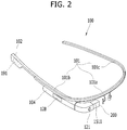
- FIG. 2 is a perspective diagram of a front surface provided in the glass type mobile terminal100 in accordance with the first embodiment of the present disclosure.
- the glass type mobile terminal 100 of the present disclosure includes a band frame 101, a housing 102 and 104, a light transmissive lens 1511 and a camera 121.
- the band frame 101 includes a front portion 101a disposed in an upper portion with respect to the user's eye and a lateral portion 101b extended from the front portion 101a toward the user's ears.
- the band frame 101 is worn on the user's head, with the front portion 101a and the lateral portion 101b surrounding a front part and a lateral part of the user's head.
- the band frame 101 has to be wearable on anyone's head, regardless of the head size, and it may be formed of an elastic material (e.g., metal and transformable plastic).
- an elastic material e.g., metal and transformable plastic
- the band frame 101a may have a clean appearance and looks thin effectively.
- the metallic part of the band frame 101 may be used as an antenna.
- the housing 102 and 104 is coupled to the lateral portion 101b of the band frame 101.
- a controller 180 In the housing 102 and 104 are provided a controller 180, a battery 191, a wireless communication unit 110, a projector (1410, see FIG. 4 ), the camera 121 and the voice output unit 152.
- the housing 102 and 104 In the FIG. 2 , the housing 102 and 104 is coupled to a predetermined portion of the band frame 101b.
- the housing may be coupled to the other opposite portion 101c of the band frame 101.
- the projector 1510 mentioned above may be provided in a housing 104 arranged adjacent to the front portion 101a, to provide an image to the light transmissive lens 1511.
- the light transmissive lens 1511 may be directly coupled to the band frame 101.
- the light transmissive lens 1511 may be coupled to the band frame 101 through the housing 104 as shown in FIG. 2 .
- the light transmissive lens 1511 is coupled to the band frame 101 or the housing 104, to be located in front of the user's eyes when the user wears the glass type mobile terminal 100 on the head.
- the light transmissive lens 1511 may be large enough to cover all portions of the user's eyes. As shown in FIG. 2 , the light transmissive lens 1511 may be located in an area a little higher than the eye.
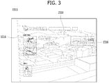
- FIG. 3 is a diagram illustrating an image focused on the light transmissive lens 1511 of the glass type mobile terminal 100 in accordance with the first embodiment of the present disclosure.
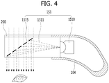
- FIGS. 4 and 5 are sectional diagrams illustrating the light transmissive lens 1511, a photo shutter 200 and the projector 1510 provided in the glass type mobile terminal 100 in accordance with the first embodiment of the present disclosure.
- the light transmissive lens 1511 transmits light there through.
- an object and a view located in front of the user may meet the user's eyes through the light transmissive lens 1511.
- the projector 1510 provided in a lateral surface of the light transmissive lens 1511 supplies an image (or light) based on image information and the image supplied from the lateral surface is focused on the transparent screen 1515.
- the image focused on the transparent screen 1515 is seen by the user.
- the transparent screen 1515 may be realized as the light transmissive lens 1511 formed of two transparent materials with a different refractive index. In other words, a border surface between the two materials may be a transparent screen 1510 which reflects lights.
- an object or scenery 1519 located in front of the light transmissive lens 1511 meets the user's eyes and an image 1516 supplied from the flanking projector 1510 is reflected on the transparent screen 1515 to be incident on the user's eyes simultaneously, such that two images may be overlappedly seen.
- the glass type mobile terminal may include a photo shutter 200 provided in a front surface of the light transmissive lens 1511 and the photo shutter 200 has a variable transparency.
- the transparency of the photo shutter 200 is variable to selectively block the light incident from the front surface of the light transmissive lens 1511. Accordingly, in a state where the photo shutter 200 is transparent, an object or scenery located in front is seen as shown in FIG. 3 and in a state where the photo shutter 200 is opaque, the image 1516 supplied from the projector 1510 may be seen clearly as shown in FIG. 5 .
- FIGS. 6 and 7c are diagrams illustrating the photo shutter 200 of the glass type mobile terminal 100 in accordance with the embodiment of the present disclosure.
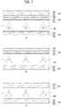
- FIG. 6 illustrates one embodiment using PDLC (Polymer Dispersed Liquid Crystal).
- PDLC 230 is characterized to control transmittance of light based on a scattering strength of light, only to omit a polarizing plate. Compared with a conventional liquid crystal, PDLC can realize a high degree of visibility and a high response speed. In addition, PDLC can reduce the cost of a liquid crystal material.
- liquid crystal particle elements 231 are scattered in polymer and liquid crystal particles 231 are provided in a net-shaped polymer.
- liquid crystal particles 231 are in irregular directions, without a voltage, and a refractive index of the liquid crystal particles with respect to a media causes scattering in another interface.
- a voltage is applied as shown in FIG. 6 (b) , directions of liquid crystal particles are arranged uniformly and the refractive indexes match exactly to be in a transmission state.
- the photo shutter 200 shown in FIG, 7a is formed of liquid crystals filled between a pair of transparent electrode layers 210 and 220 having transparent electrodes 212 and 222, respectively. Arrangement of liquid crystals are changed by an electromagnetic field formed between a first transparent electrode 212 disposed on a front surface (an upper surface in the drawing) of the photo shutter 200 and a second transparent electrode 222 formed on a rear surface (a lower surface in the drawing).
- a crystal type shown in FIG. 7a requires polarizing plates 213 and 223, which is different from the PDLC mentioned above.
- a first polarizing plate 213 coupled to a first glass 211 provided in a front surface lies at right angles to a second polarizing plate 223 coupled to a second glass 221 provided in a rear surface.
- the polarizing plates 213 and 223 lying at right angles to each other may stop light from transmitting there through.
- the glass 211 and 221 may be formed of glass or transparent resin and the transparent electrode 212 and 222 disposed in the glass 211 and 221 may be formed of ITO.
- a touch sensing function may be provided to the photo shutter 200 to perform user inputs generated by the user's touch of the light transmissive lens 1511.
- a touch sensor 250, 251, 252, 253 is disposed on a front surface of the photo shutter 200 to realize a touch function.
- the transparent electrodes 212 and 222 of the photo shutter 200 may be used as transparent electrodes of the touch sensor 250 at the same time (see FIGS. 7b and 7c ).
- a third transparent electrode 255 is further provided which is disposed on a front surface of the photo shutter 200.
- the third transparent electrode 255 disposed on the front surface and the first transparent electrode 212 disposed in the first glass 211 are employed as the touch sensor.
- the first transparent electrode of the first glass and the second transparent electrode 222 of the second glass 221 are employed as the photo shutter 200.
- the touch sensor recognizes that a touch is generated once a capacity formed between two electrodes changes.
- the first transparent electrode 212 is connected to the power for touch operation and the third transparent electrode 222 reads capacity change, only to recognize touch.
- the first transparent electrode 212 and the second transparent electrode 222 not only change the arrangement of the liquid crystals for the function as the photo shutter 200 but also performs the function of the touch sensor. Except the time taken to realize the function of the photo shutter 200, a signal for touch sensing is generated and a touch function is realized simultaneously.
- FIGS. 8 and 9 are diagrams illustrating embodiments of a method for controlling the glass type mobile terminal 100 in accordance of the embodiment of the present disclosure.
- the photo shutter 200 may be driven.
- the touch sensor 250 provided in the front surface of the photo shutter 200, the photo shutter 200 may be driven as shown in FIG. 9 .
- the user input unit 128 provided in the lateral surface may be realized by the touch sensor.
- the user input unit 128 may be realized by a button using a metallic dome, a slide key or diverse user input types.
- touch or touch and drag may be applied as a command for driving the photo shutter 200.
- a level of transparency may be controlled based on the number of times being touched (hereinafter, the number of touches) and the transparency may be adjusted based on a dragged distance or direction. For example, when a touch and drag input is sensed in a first direction, a transparency of the photo shutter 200 is lowered. When a touch and drag input is sensed in a second direction, the transparency of the photo shutter 200 is heightened.
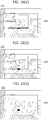
- FIG. 10 is a diagram illustrating an image focused on the transparent screen 1515 based on control of the photo shutter 200 provided in the glass type mobile terminal 100 in accordance with one embodiment of the present disclosure.
- FIG. 10 (a) illustrates a screen shown at 80% of transparency. As the transparency of the photo shutter 300 is getting heightened more and more, an object located in front is seen overlapped with the image and the image 1516 is not seen clearly.
- (b) seems more clearly than (a) and (c) shows a case in that the transparency is 0%.
- the image 1516 is seen clear, without being overlapped with the object located in front.
- the transparency of the front surface of the light transmissive lens 1511 is changed, using the photo shutter 200.
- the light drawn from the front surface may be blocked and the visibility of the image 1516 provided from the flanking projector 1510 may be enhanced.
- the photo shutter 200 is partially changed opaque and the portion not provided with the image may be controlled to make the object or scenery located in front seen.
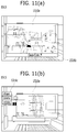
- FIG. 11 is a diagram illustrating the image focused on the light transmissive lens 1511 based on the control of the photo shutter 200 of the glass type mobile terminal 100 in accordance with the embodiment of the present disclosure.
- An image portion 1516a of the image has no great difficult in seeing the image, even with a lower visibility.
- a text portion 1516b such as subscription has difficulty in reading if the visibility is lowered.
- the photo shutter 200 may change the transparency partially, after analyzing the image, or the user may determine the portion of the photo shutter 200 which will be changed to be opaque, using the touch sensor.
- FIG. 12 is a graph illustrating a method for controlling a photo-shutter provided in a glass type mobile terminal in accordance with one embodiment of the present disclosure, with respect to external illumination.
- a curve on the graph shows a transmittance degree based on external illumination. Even when the transmittance degree is high in a lower external illumination (or transparent), the image provided from the projector 1510 is seen clear. However, when the transmittance degree is low in a high external illumination (opaque), the image focused on the transparent screen 1510 is seen clear.
- the transparency of the photo shutter 200 may be controlled based on the external illumination.
- the transparency may be changed and controlled in a stepped type.
- the transmittance level is changed step by step, when the illumination is changed to a preset size or more.
- the visibility of the image focused on the light transmissive lens 1511 may be enhanced and a clear image may be seen even in a bright place.
Landscapes
- Engineering & Computer Science (AREA)
- Theoretical Computer Science (AREA)
- Physics & Mathematics (AREA)
- General Engineering & Computer Science (AREA)
- General Physics & Mathematics (AREA)
- Computer Hardware Design (AREA)
- Human Computer Interaction (AREA)
- Computer Networks & Wireless Communication (AREA)
- Signal Processing (AREA)
- Multimedia (AREA)
- Optics & Photonics (AREA)
- Computer Graphics (AREA)
- Software Systems (AREA)
- Telephone Set Structure (AREA)
- Liquid Crystal (AREA)
Description
- Embodiments of the present disclosure relates to a glass type mobile terminal including a camera and a light transmissive lens, which may acquire and use information easily, while living a daily life.
- Terminals may be generally classified as mobile/portable terminals or stationary terminals according to their mobility. Mobile terminals may also be classified as handheld terminals or vehicle mounted terminals according to whether or not a user can directly carry the terminal.
- Mobile terminals have become increasingly more functional. Examples of such functions include data and voice communications, capturing images and video via a camera, recording audio, playing music files via a speaker system, and displaying images and video on a display. Some mobile terminals include additional functionality which supports game playing, while other terminals are configured as multimedia players. More recently, mobile terminals have been configured to receive broadcast and multicast signals which permit viewing of content such as videos and television programs.
- Recently, interests in wearable mobile terminals are increasing because they have convenient usage. Researches and developments are ongoing for diverse wearable typed mobile terminals which can be put on human body parts or clothes (e.g., glasses, bracelets, watches and so on).
US5572343 A discloses a head mounted see-through display including a liquid crystal shutter over the display.US2013/321462 A1 discloses glasses having a liquid crystal shutter to control attenuation of incident light. - An object of the present disclosure is to provide a wearable glass type mobile terminal which may enhance visibility of an image focused on a transparent screen provided therein.
- To achieve these objects and other advantages and in accordance with the purpose of the disclosure, as embodied and broadly described herein.
- Embodiments of the present disclosure provide a glass type mobile terminal according to
clam 1. - The glass type mobile terminal may further include a touch sensor coupled to the front surface of the light transmissive lens to sense capacity change so as to receive an input touch signal.
- The transparency of the photo shutter may be controlled based on the number of the touches input to the touch sensor.
- The controller may control transparency of a portion of the photo shutter where the touch input is sensed by the touch sensor.
- The controller may control the transparency of the photo shutter to be lowered, when a touch and drag input is sensed by the touch sensor in a first direction, and to be heightened, when a touch and drag input is sensed by the touch sensor in a second direction.
- The photo shutter may include a first transparent glass having a first transparent electrode formed in one surface thereof; a second transparent glass having a second transparent electrode formed in the other surface thereof, with spaced apart from one surface of the first electrode layer; a liquid crystal layer having liquid crystals filled between the first and second transparent glasses; a first polarizing plate coupled to the first transparent glass to arrange lights in one direction; and a second polarizing plate coupled to the second transparent glass to arrange lights in a vertical direction with respect to the first polarizing plate.
- The glass type mobile terminal may further include a third transparent electrode formed in an opposite surface of a surface where the second transparent electrode of the second transparent glass is formed or the first polarizing plate, wherein the controller determines presence of a touch input by sensing capacity change between the first transparent electrode and the second transparent electrode.
- The controller may control arrangement of liquid crystals by applying a signal to the first transparent electrode and the second transparent electrode at preset intervals, and determine presence of a touch input by sensing capacity change between the first transparent electrode and the second transparent electrode, when the first transparent electrode and the second transparent electrode are not used for control of the liquid crystal arrangement.
- The photo shutter may include PDLC (Polymer Dispersed Liquid Crystal).
- The glass type mobile terminal may further include a proximity illumination sensor for sensing light nearby, wherein the controller controls the transparency of the photo shutter based on illumination sensed by the proximity illumination sensor.
- A control rate of the transparency when the illumination is high may be higher than a control rate of the transparency when the illumination is low.
- The photo shutter selectively may control transparency possessed by each of divided portions.
- The controller may control the photo shutter to lower transparency of a text portion of the image than transparency of the other portion.
- The glass type mobile terminal may further include a video output unit for providing an image from a lateral surface of the light transmissive lens.
- The transparent screen is tilted to transmit an image incident from the lateral surface of the light transmissive lens.
- The glass type mobile terminal may further include an acceleration sensor, wherein the controller heightens transparency of the photo shutter, when the acceleration sensor senses movement for a preset time or more in a state of lowering the transparency of the photo sensor, and the controller lowers the transparency of the photo shutter again, when the acceleration sensor does not sense the movement in a preset time or more.
- The glass type mobile terminal may further include a touch pad coupled to the band frame to be located in the user's side, wherein the controller controls the image to have a pointer moving in response to the touch input, when the user's touch input to the touch pad is sensed.
- Further scope of applicability of the present invention will become apparent from the detailed description given hereinafter. However, it should be understood that the detailed description and specific examples, while indicating preferred embodiments of the invention, are given by illustration only, since various changes and modifications within the scope of the invention will become apparent to those skilled in the art from this detailed description.
- The present invention will become more fully understood from the detailed description given herein below and the accompanying drawings, which are given by illustration only, and thus are not limitative of the present invention, and wherein:
-
FIG. 1 is a block diagram of a mobile terminal in accordance with the present disclosure; -
FIG. 2 is a perspective diagram of a glass type mobile terminal in accordance with one embodiment of the present disclosure; -
FIG. 3 is a diagram illustrating an image focused on a light transmissive lens provided in a glass type mobile terminal in accordance with one embodiment of the present disclosure; -
FIGS. 4 and5 are sectional diagrams illustrating a light transmissive lens, a photo shutter and a projector provided in a glass type mobile terminal in accordance with one embodiment of the present disclosure; -
FIGS. 6 and7 are diagrams illustrating a photo shutter provided in a glass type mobile terminal in accordance with one embodiment of the present disclosure; -
FIGS. 8 and9 are diagrams illustrating a control method of a glass type mobile terminal in accordance with various embodiments of the present disclosure; -
FIG. 10 is a diagram illustrating an image focused on a light transmissive lens provided in a glass type mobile terminal in accordance with one embodiment of the present disclosure; -
FIG. 11 is a diagram illustrating an image focused on a light transmissive lens based on a control of a photo shutter provided in a glass type mobile terminal in accordance with one embodiment of the present disclosure; and -
FIG. 12 is a graph illustrating a method for controlling a photo-shutter provided in a glass type mobile terminal in accordance with one embodiment of the present disclosure, with respect to external illumination. - Description will now be given in detail according to exemplary embodiments disclosed herein, with reference to the accompanying drawings. For the sake of brief description with reference to the drawings, the same or equivalent components may be provided with the same reference numbers, and description thereof will not be repeated. In general, a suffix such as "module" and "unit" may be used to refer to elements or components. Use of such a suffix herein is merely intended to facilitate description of the specification, and the suffix itself is not intended to give any special meaning or function. In the present disclosure, that which is well-known to one of ordinary skill in the relevant art has generally been omitted for the sake of brevity. The accompanying drawings are used to help easily understand various technical features and it should be understood that the embodiments presented herein are not limited by the accompanying drawings.
- Reference is now made to
FIG. 1 , whereFIG. 1 is a block diagram of a mobile terminal in accordance with the present disclosure. - Referring now to
FIG. 1A , the glass typemobile terminal 100 is shown havingwireless communication unit 110 configured with several commonly implemented components. For instance, thewireless communication unit 110 typically includes one or more components which permit wireless communication between the glass typemobile terminal 100 and a wireless communication system or network within which the mobile terminal is located. - In the following description, the above elements of the glass type
mobile terminal 100 are explained in sequence. - First of all, the
wireless communication unit 110 typically includes one or more components which permits wireless communication between the glass typemobile terminal 100 and a wireless communication system or network within which themobile terminal 100 is located. For instance, thewireless communication unit 110 can include amobile communication module 112, awireless internet module 113, a short-range communication module 114, a position-location module 115 and the like. - The
mobile communication module 112 transmits/receives wireless signals to/from one or more network entities (e.g., base station, external terminal, server, etc.) via a mobile network such as GSM(Gobal System for Mobile communications), CDMA(Code Division Multiple Access), WCDMA(Wideband CDMA) and so on. Such wireless signals may represent audio, video, and data according to text/multimedia message transmission and reception, among others. - The
wireless internet module 113 supports Internet access for themobile terminal 100. This module may be internally or externally coupled to themobile terminal 100. In this case, the wireless Internet technology can include WLAN(Wireless LAN) (Wi-Fi), Wibro (Wireless broadband), Wimax (World Interoperability for Microwave Access), HSDPA(High Speed Downlink Packet Access), GSM, CDMA, WCDMA, LTE (Long Term Evolution) etc. - Wireless internet access by Wibro, HSPDA, GSM, CDMA, WCDMA, LTE or the like is achieved via a mobile communication network. In this aspect, the
wireless internet module 113 configured to perform the wireless internet access via the mobile communication network can be understood as a sort of themobile communication module 112. - The short-
range communication module 114 facilitates relatively short-range communications. Suitable technologies for implementing this module include radio frequency identification (RFID), infrared data association (IrDA), ultra-wideband (UWB), as well at the networking technologies commonly referred to as Bluetooth and ZigBee, to name a few. - The position-
location module 115 identifies or otherwise obtains the location of themobile terminal 100. If desired, this module may be implemented with a global positioning system (GPS) module. According to the current technology, theGPS module 115 is able to precisely calculate current 3-dimensional position information based on at least one of longitude, latitude and altitude and direction (or orientation) by calculating distance information and precise time information from at least three satellites and then applying triangulation to the calculated information. Currently, location and time information are calculated using three satellites, and errors of the calculated location position and time information are then amended using another satellite. Besides, theGPS module 115 is able to calculate speed information by continuously calculating a real-time current location. - Referring to
FIG. 1 , theinput unit 120 may be configured to provide audio or video signal input to themobile terminal 100. As shown, the A/V input unit 120 includes acamera 121 and amicrophone 122. Thecamera 121 receives and processes image frames of still pictures or video, which are obtained by an image sensor in a video call mode or a photographing mode. In addition, the processed image frames can be displayed on thedisplay 151 of theoutput unit 150. - The image frames processed by the
camera 121 can be stored in thememory 160 or can be externally transmitted via thewireless communication unit 110. Optionally, at least twocameras 121 can be provided to the glass typemobile terminal 100 according to environment of usage. - The
microphone 122 receives an external audio signal while the portable device is in a particular mode, such as phone call mode, recording mode and voice recognition. This audio signal is processed and converted into electric audio data. The processed audio data is transformed into a format transmittable to a mobile communication base station via themobile communication module 112 in case of a call mode. Themicrophone 122 typically includes assorted noise removing algorithms to remove noise generated in the course of receiving the external audio signal. - An
image recognition unit 125 is a device configured to extract information from an image photographed by thecamera 121 and theimage recognition unit 125 may identify the photographed image. In case the photographed image has a character, the image recognition unit converts a character into text data. In case the image has a plurality of objects, the image recognition unit extracts an object which will be compared with information stored in thememory 160. - In case the
camera 121 photographs a motion picture, the motion picture consists of still images and theimage recognition unit 125 acquires information of all the still images and the controller processes the acquired information. However, this process might be unnecessary waste. In addition, if such unnecessary information is extracted and provided to a user, it is inconvenient of a user to use a glass typemobile terminal 100 wearable like glasses. - When the user presses the
user input unit 128 provided in the frame or uses a voice command for acquiring image information, the user can extract necessary information. Alternatively, when looking at one object for more than a preset time period, thecamera 121 may photograph the same object for more than a preset time period and information on the object may be extracted. - Alternatively, when the user approaches a specific object, the object occupies a large area of the user's view and it can be determined that the user is looking at the corresponding object. Hence, when one object of the images recognized by the
camera 121 occupies a preset range of images composing the motion picture, information on the object may be extracted. - Alternatively, the
image recognition unit 125 may recognize a gesture created by the user and processes the input gesture as a user command. For example, theimage recognition unit 125 may recognize a circle drawn by the user as "yes" or perform a function of selecting a character or object located in the circle. - A
voice recognition unit 126 may convert the user's voice inputted via the microphone 1222 into text data or recognize the user's voice as a specific command (hereinafter, "a voice command"). As the glass typemobile terminal 100 according to the present invention can include a keyboard, a function of thevoice recognition unit 126 configured to recognize the user's voice command is important so as to activate the functions of the mobile terminal. - It is difficult for the glass type
mobile terminal 100 to include the keyboard. However, the glass typemobile terminal 100 may include a button typeuser input unit 128 on the frame and a command used frequently may be inputted via the button typeuser input unit 128. For example, the user can input a command for photographing an image watched by the user or extracting information from the image or a command for controlling a volume of a sound outputted from theaudio output unit 152 via the button typeuser input unit 128. - Various types may be applicable as the
user input unit 128 and such various types includes a module for recognizing a physical pressure from a metallic dome formed therein to generate a signal. - The
sensing unit 140 senses a state of the glass typemobile terminal 100 and a user surrounding environment and such thesensing unit 140 may include agyrosensor 141 and anacceleration sensor 142. - The
gyrosensor 141 is a device configured to sense a tilted phase of the mobile terminal and tilted variation in x, y and z axes, and it can be called as an angular velocity sensor. The gyrosensor senses a rotational movement with respect to each axis to sense tilting and shaking of the mobile terminal case. - A conventional gyrosensor has a spinning top, with three axes and such a gyrosensor is developed to have an improved precision and a compact size such as an optical gyrosensor or a vibration gyrosensor recently, such that a current developing gyrosensor can be mountable in compact-sized electronics including a mobile terminal. In addition, 6-axis sensor realized by MEMS module can be used as the
gyrosensor 141. - The
gyrosensor 141 applied to the present invention is not limited to those types mentioned above and all types of gyrosensors capable of sensing tilting and motion of the glass typemobile terminal 100 can be applicable to the present invention. - The
acceleration sensor 142 may measure a dynamic force, for example, an acceleration of the glass typemobile terminal 100 and it can detect vibration, shocks and so on from acceleration change. When an object having mass is accelerated, a force is generated and variation of the force is sensed by theacceleration sensor 142. - When using the
acceleration sensor 142, the user's movement can be sensed and it can be determined whether the mobile terminal is moving or stationary. Once it is sensed by theacceleration sensor 142 that the user is walking or moving, thecontroller 180 may limit the output of images from theimage output unit 151 and an accident happening while a walking user is watching a video file may be prevented. - Next, the
output unit 150 is employed to generate outputs related with a visual, auditory or tactile sense. Theoutput unit 150 may include avideo output unit 151 and anaudio output unit 152. - The
video output unit 151 includes aprojector 1510 for outputting an image, using video information, and alight transmissive lens 1511 disposed in front of the user's eyes to provide the user with the light supplied by theprojector 1510. - The
light transmissive lens 1511 is disposed in front of the user's eyes, like lenses of glasses. Atransparent screen 1515 is provided in thelight transmissive lens 1511. The transparent screen is transparent to allow the user to see an object located in front and to reflect and make the image incident in a lateral direction reach the user's eyes. - The
audio output module 152 functions in various modes including a call-receiving mode, a call-placing mode, a recording mode, a voice recognition mode, a broadcast reception mode and the like to output audio data which is received from thewireless communication unit 110 or is stored in thememory 160. During operation, theaudio output module 152 outputs audio relating to a particular function (e.g., call received, message received, etc.). Theaudio output module 152 is often implemented using one or more speakers, receivers, bone conduction audio producing devices, and combinations thereof. - In the
memory 160 may be stored programs configured for thecontroller 180 to process and control and to implement a function for temporarily storing input/output data. Thememory 160 may store new input data therein and extract the stored data. A storage function of thememory 160 may be expanded by an SD card or an auxiliary storage device. - The
interface unit 170 is employed as a passage to all of external devices connected with the glass typemobile terminal 100. Theinterface unit 170 may be provided with data or an electric power from an external device to transmit the provided data or power to each of the components provided in the glass typemobile terminal 100 or the data stored in the glass typemobile terminal 100 to an external device. - Examples of the
interface unit 170 may include a wire/wireless headset port, an external charger port, a wire/wireless data port, a memory card port, a port for connecting a device having an identification module, an I/O (Input/Output) port, a video I/O (Input/Output) port, an earphone port and the like. - The identification module is a chip in which diverse information for user identify of the glass type
mobile terminal 100. Examples of the identification module may include UIM (User Identify Module), SIM (Subscriber Identity Module), USIM (Universal Subscriber Identity Module) and the like. The device having the identification module (hereinafter, "the identification device") may be fabricated as a smart card and the identification device may be connected with themobile terminal 100 via a port. - When the
mobile terminal 100 is connected with an external cradle, theinterface unit 170 may be a passage of the power from a cradle to themobile terminal 100 or a passage of various command signals input from the cradle by the user to the mobile terminal. The various command signals or power input from the cradle may be operating as a signal for recognizing whether the mobile terminal is mounted on the cradle precisely. - The
controller 180 typically controls overall operations of the glass typemobile terminal 100. Thecontroller 180 controls the wireless communication unit to transmit and receive diverse signals or to process the input data or it controls thelight transmissive lens 1511 and the audio output unit to provide the user with information. Theimage recognition unit 125 and thevoice recognition unit 126 mentioned above may be configured as a part of thecontroller 180. - The
controller 180 in accordance with the present disclosure may extract information from the image acquired by thecamera 121 and compare the extracted information with pre-stored information or store the extracted information in thememory 160. Or, thecontroller 180 may extract the related information stored in thememory 160 and output the extracted information to thelight transmissive lens 1511 or search for the related information on the internet. - The power supply unit 190 provides power required by the various components for the glass type
mobile terminal 100. The power may be internal power, external power, or combinations thereof. - A battery may include a built-in rechargeable battery and may be detachably attached to the terminal body for a charging and the like.
- Various embodiments described herein may be implemented in a computer-readable medium using, for example, computer software, hardware, or some combination thereof.
-
FIG. 2 is a perspective diagram of a front surface provided in the glass type mobile terminal100 in accordance with the first embodiment of the present disclosure. Referring toFIG. 2 , the glass typemobile terminal 100 of the present disclosure includes aband frame 101, ahousing light transmissive lens 1511 and acamera 121. - The band frame 101includes a
front portion 101a disposed in an upper portion with respect to the user's eye and alateral portion 101b extended from thefront portion 101a toward the user's ears. Theband frame 101 is worn on the user's head, with thefront portion 101a and thelateral portion 101b surrounding a front part and a lateral part of the user's head. - The
band frame 101 has to be wearable on anyone's head, regardless of the head size, and it may be formed of an elastic material (e.g., metal and transformable plastic). - In case it is partially formed of a metallic material, the
band frame 101a may have a clean appearance and looks thin effectively. In addition, the metallic part of theband frame 101 may be used as an antenna. - The
housing lateral portion 101b of theband frame 101. In thehousing controller 180, abattery 191, awireless communication unit 110, a projector (1410, seeFIG. 4 ), thecamera 121 and thevoice output unit 152. In theFIG. 2 , thehousing band frame 101b. The housing may be coupled to the otheropposite portion 101c of theband frame 101. - Especially, the
projector 1510 mentioned above may be provided in ahousing 104 arranged adjacent to thefront portion 101a, to provide an image to thelight transmissive lens 1511. Thelight transmissive lens 1511 may be directly coupled to theband frame 101. However, thelight transmissive lens 1511 may be coupled to theband frame 101 through thehousing 104 as shown inFIG. 2 . - The
light transmissive lens 1511 is coupled to theband frame 101 or thehousing 104, to be located in front of the user's eyes when the user wears the glass typemobile terminal 100 on the head. Thelight transmissive lens 1511 may be large enough to cover all portions of the user's eyes. As shown inFIG. 2 , thelight transmissive lens 1511 may be located in an area a little higher than the eye. -
FIG. 3 is a diagram illustrating an image focused on thelight transmissive lens 1511 of the glass typemobile terminal 100 in accordance with the first embodiment of the present disclosure.FIGS. 4 and5 are sectional diagrams illustrating thelight transmissive lens 1511, aphoto shutter 200 and theprojector 1510 provided in the glass typemobile terminal 100 in accordance with the first embodiment of the present disclosure. - The
light transmissive lens 1511 transmits light there through. When the user wears the glass typemobile terminal 100 on the head, an object and a view located in front of the user may meet the user's eyes through thelight transmissive lens 1511. - The
projector 1510 provided in a lateral surface of thelight transmissive lens 1511 supplies an image (or light) based on image information and the image supplied from the lateral surface is focused on thetransparent screen 1515. The image focused on thetransparent screen 1515 is seen by the user. Thetransparent screen 1515 may be realized as thelight transmissive lens 1511 formed of two transparent materials with a different refractive index. In other words, a border surface between the two materials may be atransparent screen 1510 which reflects lights. - Accordingly, an object or
scenery 1519 located in front of thelight transmissive lens 1511 meets the user's eyes and animage 1516 supplied from the flankingprojector 1510 is reflected on thetransparent screen 1515 to be incident on the user's eyes simultaneously, such that two images may be overlappedly seen. - As the two
images image 1516 supplied from theprojector 1510 properly and it is necessary to block the light 1519 incident in a forward direction so as to make theimage 1516 supplied from theprojector 1510 seen clearly. - To meet the necessity, the glass type mobile terminal according to the present disclosure may include a
photo shutter 200 provided in a front surface of thelight transmissive lens 1511 and thephoto shutter 200 has a variable transparency. The transparency of thephoto shutter 200 is variable to selectively block the light incident from the front surface of thelight transmissive lens 1511. Accordingly, in a state where thephoto shutter 200 is transparent, an object or scenery located in front is seen as shown inFIG. 3 and in a state where thephoto shutter 200 is opaque, theimage 1516 supplied from theprojector 1510 may be seen clearly as shown inFIG. 5 . -
FIGS. 6 and7c are diagrams illustrating thephoto shutter 200 of the glass typemobile terminal 100 in accordance with the embodiment of the present disclosure.FIG. 6 illustrates one embodiment using PDLC (Polymer Dispersed Liquid Crystal).PDLC 230 is characterized to control transmittance of light based on a scattering strength of light, only to omit a polarizing plate. Compared with a conventional liquid crystal, PDLC can realize a high degree of visibility and a high response speed. In addition, PDLC can reduce the cost of a liquid crystal material. - Several millimeters of liquid
crystal particle elements 231 are scattered in polymer andliquid crystal particles 231 are provided in a net-shaped polymer. As shown inFIG. 6 (a) ,liquid crystal particles 231 are in irregular directions, without a voltage, and a refractive index of the liquid crystal particles with respect to a media causes scattering in another interface. When a voltage is applied as shown inFIG. 6 (b) , directions of liquid crystal particles are arranged uniformly and the refractive indexes match exactly to be in a transmission state. - The
photo shutter 200 shown inFIG, 7a is formed of liquid crystals filled between a pair oftransparent electrode layers transparent electrodes transparent electrode 212 disposed on a front surface (an upper surface in the drawing) of thephoto shutter 200 and a secondtransparent electrode 222 formed on a rear surface (a lower surface in the drawing). - A crystal type shown in
FIG. 7a requirespolarizing plates polarizing plate 213 coupled to afirst glass 211 provided in a front surface lies at right angles to a secondpolarizing plate 223 coupled to asecond glass 221 provided in a rear surface. When theliquid crystals 235 are arranged uniformly after the electric power applied to the firsttransparent electrode 212 and the secondtransparent electrode 222, thepolarizing plates liquid crystals 235 is not uniform and a direction of a light wavelength is bending while transmitting the liquid crystals and the light can transmit thepolarizing plates glass transparent electrode glass - A touch sensing function may be provided to the
photo shutter 200 to perform user inputs generated by the user's touch of thelight transmissive lens 1511. As shown inFIG. 7a , atouch sensor photo shutter 200 to realize a touch function. To realize a reduced thickness and to reduce material costs, thetransparent electrodes photo shutter 200 may be used as transparent electrodes of thetouch sensor 250 at the same time (seeFIGS. 7b and 7c ). - In one embodiment of the
photo shutter 200 shown inFIG. 7b , a thirdtransparent electrode 255 is further provided which is disposed on a front surface of thephoto shutter 200. The thirdtransparent electrode 255 disposed on the front surface and the firsttransparent electrode 212 disposed in thefirst glass 211 are employed as the touch sensor. The first transparent electrode of the first glass and the secondtransparent electrode 222 of thesecond glass 221 are employed as thephoto shutter 200. - The touch sensor recognizes that a touch is generated once a capacity formed between two electrodes changes. The first
transparent electrode 212 is connected to the power for touch operation and the thirdtransparent electrode 222 reads capacity change, only to recognize touch. - In one embodiment of the
photo shutter 200 shown inFIG. 7c , the firsttransparent electrode 212 and the secondtransparent electrode 222 not only change the arrangement of the liquid crystals for the function as thephoto shutter 200 but also performs the function of the touch sensor. Except the time taken to realize the function of thephoto shutter 200, a signal for touch sensing is generated and a touch function is realized simultaneously. -
FIGS. 8 and9 are diagrams illustrating embodiments of a method for controlling the glass typemobile terminal 100 in accordance of the embodiment of the present disclosure. Using theuser input unit 128 provided in a lateral side of the glass typemobile terminal 100, thephoto shutter 200 may be driven. Using thetouch sensor 250 provided in the front surface of thephoto shutter 200, thephoto shutter 200 may be driven as shown inFIG. 9 . - The
user input unit 128 provided in the lateral surface may be realized by the touch sensor. Alternatively, theuser input unit 128 may be realized by a button using a metallic dome, a slide key or diverse user input types. In case of using the touch sensor, touch or touch and drag may be applied as a command for driving thephoto shutter 200. - A level of transparency may be controlled based on the number of times being touched (hereinafter, the number of touches) and the transparency may be adjusted based on a dragged distance or direction. For example, when a touch and drag input is sensed in a first direction, a transparency of the
photo shutter 200 is lowered. When a touch and drag input is sensed in a second direction, the transparency of thephoto shutter 200 is heightened. - In case of using the touch sensor coupled to the front surface of the
photo shutter 200, transparency of a touched portion of thephoto shutter 200 may be controlled. -
FIG. 10 is a diagram illustrating an image focused on thetransparent screen 1515 based on control of thephoto shutter 200 provided in the glass typemobile terminal 100 in accordance with one embodiment of the present disclosure.FIG. 10 (a) illustrates a screen shown at 80% of transparency. As the transparency of the photo shutter 300 is getting heightened more and more, an object located in front is seen overlapped with the image and theimage 1516 is not seen clearly. - In
FIG. 10 , (b) seems more clearly than (a) and (c) shows a case in that the transparency is 0%. In (c), theimage 1516 is seen clear, without being overlapped with the object located in front. In other words, the transparency of the front surface of thelight transmissive lens 1511 is changed, using thephoto shutter 200. The light drawn from the front surface may be blocked and the visibility of theimage 1516 provided from the flankingprojector 1510 may be enhanced. As shown inFIG. 10 (c) , thephoto shutter 200 is partially changed opaque and the portion not provided with the image may be controlled to make the object or scenery located in front seen. -
FIG. 11 is a diagram illustrating the image focused on thelight transmissive lens 1511 based on the control of thephoto shutter 200 of the glass typemobile terminal 100 in accordance with the embodiment of the present disclosure. Animage portion 1516a of the image has no great difficult in seeing the image, even with a lower visibility. However, atext portion 1516b such as subscription has difficulty in reading if the visibility is lowered. - Accordingly, it is necessary that the text portion (1516b, see
FIG. 11 (a) ) or a menu portion (1516c, seeFIG. 11 (b) ) should be seen clear for control, such that only a predetermined portion of thephoto shutter 200 may be opaque to enhance the visibility partially. - The
photo shutter 200 may change the transparency partially, after analyzing the image, or the user may determine the portion of thephoto shutter 200 which will be changed to be opaque, using the touch sensor. -
FIG. 12 is a graph illustrating a method for controlling a photo-shutter provided in a glass type mobile terminal in accordance with one embodiment of the present disclosure, with respect to external illumination. A curve on the graph shows a transmittance degree based on external illumination. Even when the transmittance degree is high in a lower external illumination (or transparent), the image provided from theprojector 1510 is seen clear. However, when the transmittance degree is low in a high external illumination (opaque), the image focused on thetransparent screen 1510 is seen clear. - Accordingly, the transparency of the
photo shutter 200 may be controlled based on the external illumination. In case the illumination is changed to a preset size or more for efficiency, the transparency may be changed and controlled in a stepped type. When the transmittance is changed even with small illumination change, the user can feel dizzy. It is preferred that the transmittance level is changed step by step, when the illumination is changed to a preset size or more. - As mentioned above, the visibility of the image focused on the
light transmissive lens 1511 may be enhanced and a clear image may be seen even in a bright place. - When a particular feature, structure, or characteristic is described in connection with any embodiment, it is submitted that it is within the purview of one skilled in the art to affect such feature, structure, or characteristic in connection with other ones of the embodiments.
- Although embodiments have been described with reference to a number of illustrative embodiments thereof, it should be understood that numerous other modifications and embodiments can be devised by those skilled in the art that will fall within the scope of the appended claims. More particularly, various variations and modifications are possible in the component parts and/or arrangements of the subject combination arrangement within the scope of the disclosure, the drawings and the appended claims. In addition to variations and modifications in the component parts and/or arrangements, alternative uses will also be apparent to those skilled in the art.
Claims (3)
- A glass type mobile terminal comprising:a band frame (101) wearable on a user' s head;a light transmissive lens (1511) coupled to the band frame to be located in front the user wearing the band frame, the light transmissive lens comprising a transparent screen (1511) where an image is focused;a projector (1510) for outputting an image toward the transparent screen from a lateral surface of the light transmissive lens;a photo shutter (200) coupled to a front surface of the light transmissive lens, with a controllable transparency;a touch sensor (128) configured to sense touch inputs; anda controller (180) for controlling the transparency of the photo shutter,characterized in that the photo shutter comprises,
a first transparent glass having a first transparent electrode layer (212) formed on a first surface;
a second transparent glass having a second transparent electrode layer (222) formed on a second surface such that the second transparent electrode layer is spaced apart from the first transparent electrode layer;
a liquid crystal layer (235) formed by liquid crystals between the first and second transparent glass;
a first polarizing plate (213) coupled to the first transparent glass and configured to arrange light in a first direction; and
a second polarizing plate (223) coupled to the second transparent glass and configured to arrange light in a second direction vertical to the first direction,
wherein at least the first transparent electrode layer or the second transparent electrode layer is used as a transparent electrode of both the photo shutter and touch sensor at the same time. - The glass type mobile terminal of claim 1, wherein the touch sensor comprises at least the first transparent electrode layer or second transparent electrode layer; and a third transparent electrode formed in an opposite surface of a surface where the second transparent electrode of the second transparent glass is formed or the first polarizing plate,
wherein the controller determines presence of a touch input by sensing capacity change between the first transparent electrode and the third transparent electrode. - The glass type mobile terminal of claim 1, wherein the controller controls arrangement of liquid crystals by applying a signal to the first transparent electrode and the second transparent electrode at preset intervals, and determines presence of a touch input by sensing capacity change between the first transparent electrode and the second transparent electrode, when the first transparent electrode and the second transparent electrode are not used for control of the liquid crystal arrangement.
Applications Claiming Priority (1)
| Application Number | Priority Date | Filing Date | Title |
|---|---|---|---|
| KR1020140058431A KR20150131577A (en) | 2014-05-15 | 2014-05-15 | Glass Type Terminal |
Publications (3)
| Publication Number | Publication Date |
|---|---|
| EP2952999A2 EP2952999A2 (en) | 2015-12-09 |
| EP2952999A3 EP2952999A3 (en) | 2016-03-09 |
| EP2952999B1 true EP2952999B1 (en) | 2019-10-09 |
Family
ID=52396368
Family Applications (1)
| Application Number | Title | Priority Date | Filing Date |
|---|---|---|---|
| EP14200648.5A Active EP2952999B1 (en) | 2014-05-15 | 2014-12-30 | Wearable mobile terminal with improved photo shutter and touch sensor |
Country Status (3)
| Country | Link |
|---|---|
| US (1) | US9569896B2 (en) |
| EP (1) | EP2952999B1 (en) |
| KR (1) | KR20150131577A (en) |
Families Citing this family (6)
| Publication number | Priority date | Publication date | Assignee | Title |
|---|---|---|---|---|
| KR102187848B1 (en) * | 2014-03-19 | 2020-12-07 | 삼성전자 주식회사 | Method for displaying visual media using projector and wearable electronic device implementing the same |
| US10371944B2 (en) * | 2014-07-22 | 2019-08-06 | Sony Interactive Entertainment Inc. | Virtual reality headset with see-through mode |
| CN104155772B (en) * | 2014-08-04 | 2016-01-27 | 联想(北京)有限公司 | A kind of wearable device and electronics storing equipment |
| CN105828056B (en) * | 2016-06-07 | 2017-09-05 | 于卫华 | Portable mobile WiFi intelligence projection devices |
| KR102328618B1 (en) * | 2018-12-19 | 2021-11-18 | 한국광기술원 | Apparatus and Method for Attenuating Light Reactively |
| KR102594976B1 (en) * | 2021-08-13 | 2023-10-26 | 백진욱 | Apparatus of selecting video content, user terminal and method of providing video content for augmented reality |
Citations (1)
| Publication number | Priority date | Publication date | Assignee | Title |
|---|---|---|---|---|
| US20100182273A1 (en) * | 2008-03-28 | 2010-07-22 | Sony Corporation | Display device with touch sensor |
Family Cites Families (20)
| Publication number | Priority date | Publication date | Assignee | Title |
|---|---|---|---|---|
| US5572343A (en) | 1992-05-26 | 1996-11-05 | Olympus Optical Co., Ltd. | Visual display having see-through function and stacked liquid crystal shutters of opposite viewing angle directions |
| WO2003007049A1 (en) * | 1999-10-05 | 2003-01-23 | Iridigm Display Corporation | Photonic mems and structures |
| US7185983B2 (en) | 2004-04-13 | 2007-03-06 | Andrew Nelson | System and method for displaying information on athletic eyewear |
| US20060001655A1 (en) * | 2004-07-01 | 2006-01-05 | Koji Tanabe | Light-transmitting touch panel and detection device |
| US20090040308A1 (en) * | 2007-01-15 | 2009-02-12 | Igor Temovskiy | Image orientation correction method and system |
| US8797468B2 (en) | 2007-04-10 | 2014-08-05 | Nec Corporation | Liquid crystal shutter glasses |
| AU2011220382A1 (en) | 2010-02-28 | 2012-10-18 | Microsoft Corporation | Local advertising content on an interactive head-mounted eyepiece |
| WO2012040386A1 (en) * | 2010-09-21 | 2012-03-29 | 4Iiii Innovations Inc. | Head-mounted peripheral vision display systems and methods |
| EP2625845B1 (en) * | 2010-10-04 | 2021-03-03 | Gerard Dirk Smits | System and method for 3-d projection and enhancements for interactivity |
| US9213405B2 (en) | 2010-12-16 | 2015-12-15 | Microsoft Technology Licensing, Llc | Comprehension and intent-based content for augmented reality displays |
| US8194036B1 (en) | 2011-06-29 | 2012-06-05 | Google Inc. | Systems and methods for controlling a cursor on a display using a trackpad input device |
| JP5884502B2 (en) * | 2012-01-18 | 2016-03-15 | ソニー株式会社 | Head mounted display |
| JP2013174642A (en) * | 2012-02-23 | 2013-09-05 | Toshiba Corp | Image display device |
| WO2013136696A1 (en) | 2012-03-13 | 2013-09-19 | ソニー株式会社 | Head-mounted display |
| US9291823B2 (en) | 2012-03-30 | 2016-03-22 | Google Inc. | Wearable device with input and output structures |
| US9116666B2 (en) * | 2012-06-01 | 2015-08-25 | Microsoft Technology Licensing, Llc | Gesture based region identification for holograms |
| US9430055B2 (en) | 2012-06-15 | 2016-08-30 | Microsoft Technology Licensing, Llc | Depth of field control for see-thru display |
| JP5351311B1 (en) | 2012-06-29 | 2013-11-27 | 株式会社ソニー・コンピュータエンタテインメント | Stereoscopic image observation device and transmittance control method |
| US9158114B2 (en) | 2012-11-05 | 2015-10-13 | Exelis Inc. | Image display utilizing a variable mask to selectively block image data |
| WO2015076812A1 (en) * | 2013-11-21 | 2015-05-28 | Empire Technology Development Llc | Secure transparent display |
-
2014
- 2014-05-15 KR KR1020140058431A patent/KR20150131577A/en not_active Abandoned
- 2014-12-11 US US14/567,643 patent/US9569896B2/en active Active
- 2014-12-30 EP EP14200648.5A patent/EP2952999B1/en active Active
Patent Citations (1)
| Publication number | Priority date | Publication date | Assignee | Title |
|---|---|---|---|---|
| US20100182273A1 (en) * | 2008-03-28 | 2010-07-22 | Sony Corporation | Display device with touch sensor |
Also Published As
| Publication number | Publication date |
|---|---|
| EP2952999A2 (en) | 2015-12-09 |
| KR20150131577A (en) | 2015-11-25 |
| EP2952999A3 (en) | 2016-03-09 |
| US20150332502A1 (en) | 2015-11-19 |
| US9569896B2 (en) | 2017-02-14 |
Similar Documents
| Publication | Publication Date | Title |
|---|---|---|
| KR102102643B1 (en) | Glass Type Terminal | |
| KR102056193B1 (en) | Mobile terminal and method for controlling the same | |
| US9939642B2 (en) | Glass type terminal and control method thereof | |
| US9569896B2 (en) | Glass type mobile terminal | |
| US10261671B2 (en) | Mobile terminal and method for controlling the same | |
| CN106201302B (en) | Mobile terminal and control method for the same | |
| EP3086216B1 (en) | Mobile terminal and controlling method thereof | |
| US20180157043A1 (en) | Head mounted display | |
| CN109788089A (en) | Macro imaging method and terminal | |
| EP3107278A2 (en) | Mobile terminal and method of controlling the same | |
| EP2947867A1 (en) | Mobile terminal and method of controlling the same | |
| KR20120102365A (en) | Mobile terminal and control method therof | |
| CN111830712A (en) | Smart glasses, assembled glasses, control method and computer storage medium | |
| US11025767B2 (en) | Mobile terminal and control method therefor | |
| KR101737840B1 (en) | Mobile terminal and method for controlling the same | |
| US10122448B2 (en) | Mobile terminal and control method therefor | |
| KR20160134334A (en) | Mobile terminal and method of controlling the same | |
| KR20150084485A (en) | Mobile terminal and controlling method thereof | |
| KR20170082228A (en) | Mobile terminal and method for controlling the same | |
| KR20170042164A (en) | Mobile terminal and method for controlling the same | |
| CN112558847B (en) | Method for controlling interface display and head-mounted display | |
| KR20150140050A (en) | Mobile terminal and method for controlling the same | |
| KR20170073985A (en) | Mobile terminal and method for controlling the same | |
| KR102234710B1 (en) | Mobile terminal and method for controlling the same | |
| CN114564162B (en) | Data transmission method, electronic device, system and storage medium |
Legal Events
| Date | Code | Title | Description |
|---|---|---|---|
| PUAI | Public reference made under article 153(3) epc to a published international application that has entered the european phase |
Free format text: ORIGINAL CODE: 0009012 |
|
| AK | Designated contracting states |
Kind code of ref document: A2 Designated state(s): AL AT BE BG CH CY CZ DE DK EE ES FI FR GB GR HR HU IE IS IT LI LT LU LV MC MK MT NL NO PL PT RO RS SE SI SK SM TR |
|
| AX | Request for extension of the european patent |
Extension state: BA ME |
|
| PUAL | Search report despatched |
Free format text: ORIGINAL CODE: 0009013 |
|
| AK | Designated contracting states |
Kind code of ref document: A3 Designated state(s): AL AT BE BG CH CY CZ DE DK EE ES FI FR GB GR HR HU IE IS IT LI LT LU LV MC MK MT NL NO PL PT RO RS SE SI SK SM TR |
|
| AX | Request for extension of the european patent |
Extension state: BA ME |
|
| RIC1 | Information provided on ipc code assigned before grant |
Ipc: G06F 1/16 20060101AFI20160129BHEP Ipc: G06T 19/00 20110101ALI20160129BHEP Ipc: G02B 27/01 20060101ALI20160129BHEP Ipc: G06F 3/041 20060101ALI20160129BHEP Ipc: H04N 9/31 20060101ALI20160129BHEP |
|
| 17P | Request for examination filed |
Effective date: 20160907 |
|
| RBV | Designated contracting states (corrected) |
Designated state(s): AL AT BE BG CH CY CZ DE DK EE ES FI FR GB GR HR HU IE IS IT LI LT LU LV MC MK MT NL NO PL PT RO RS SE SI SK SM TR |
|
| STAA | Information on the status of an ep patent application or granted ep patent |
Free format text: STATUS: EXAMINATION IS IN PROGRESS |
|
| 17Q | First examination report despatched |
Effective date: 20171113 |
|
| GRAP | Despatch of communication of intention to grant a patent |
Free format text: ORIGINAL CODE: EPIDOSNIGR1 |
|
| STAA | Information on the status of an ep patent application or granted ep patent |
Free format text: STATUS: GRANT OF PATENT IS INTENDED |
|
| INTG | Intention to grant announced |
Effective date: 20190606 |
|
| GRAS | Grant fee paid |
Free format text: ORIGINAL CODE: EPIDOSNIGR3 |
|
| GRAA | (expected) grant |
Free format text: ORIGINAL CODE: 0009210 |
|
| STAA | Information on the status of an ep patent application or granted ep patent |
Free format text: STATUS: THE PATENT HAS BEEN GRANTED |
|
| AK | Designated contracting states |
Kind code of ref document: B1 Designated state(s): AL AT BE BG CH CY CZ DE DK EE ES FI FR GB GR HR HU IE IS IT LI LT LU LV MC MK MT NL NO PL PT RO RS SE SI SK SM TR |
|
| REG | Reference to a national code |
Ref country code: GB Ref legal event code: FG4D |
|
| REG | Reference to a national code |
Ref country code: CH Ref legal event code: EP |
|
| REG | Reference to a national code |
Ref country code: IE Ref legal event code: FG4D |
|
| REG | Reference to a national code |
Ref country code: DE Ref legal event code: R096 Ref document number: 602014054836 Country of ref document: DE |
|
| REG | Reference to a national code |
Ref country code: AT Ref legal event code: REF Ref document number: 1189561 Country of ref document: AT Kind code of ref document: T Effective date: 20191115 |
|
| REG | Reference to a national code |
Ref country code: NL Ref legal event code: MP Effective date: 20191009 |
|
| REG | Reference to a national code |
Ref country code: LT Ref legal event code: MG4D |
|
| REG | Reference to a national code |
Ref country code: AT Ref legal event code: MK05 Ref document number: 1189561 Country of ref document: AT Kind code of ref document: T Effective date: 20191009 |
|
| PG25 | Lapsed in a contracting state [announced via postgrant information from national office to epo] |
Ref country code: NO Free format text: LAPSE BECAUSE OF FAILURE TO SUBMIT A TRANSLATION OF THE DESCRIPTION OR TO PAY THE FEE WITHIN THE PRESCRIBED TIME-LIMIT Effective date: 20200109 Ref country code: PL Free format text: LAPSE BECAUSE OF FAILURE TO SUBMIT A TRANSLATION OF THE DESCRIPTION OR TO PAY THE FEE WITHIN THE PRESCRIBED TIME-LIMIT Effective date: 20191009 Ref country code: AT Free format text: LAPSE BECAUSE OF FAILURE TO SUBMIT A TRANSLATION OF THE DESCRIPTION OR TO PAY THE FEE WITHIN THE PRESCRIBED TIME-LIMIT Effective date: 20191009 Ref country code: LV Free format text: LAPSE BECAUSE OF FAILURE TO SUBMIT A TRANSLATION OF THE DESCRIPTION OR TO PAY THE FEE WITHIN THE PRESCRIBED TIME-LIMIT Effective date: 20191009 Ref country code: SE Free format text: LAPSE BECAUSE OF FAILURE TO SUBMIT A TRANSLATION OF THE DESCRIPTION OR TO PAY THE FEE WITHIN THE PRESCRIBED TIME-LIMIT Effective date: 20191009 Ref country code: BG Free format text: LAPSE BECAUSE OF FAILURE TO SUBMIT A TRANSLATION OF THE DESCRIPTION OR TO PAY THE FEE WITHIN THE PRESCRIBED TIME-LIMIT Effective date: 20200109 Ref country code: FI Free format text: LAPSE BECAUSE OF FAILURE TO SUBMIT A TRANSLATION OF THE DESCRIPTION OR TO PAY THE FEE WITHIN THE PRESCRIBED TIME-LIMIT Effective date: 20191009 Ref country code: GR Free format text: LAPSE BECAUSE OF FAILURE TO SUBMIT A TRANSLATION OF THE DESCRIPTION OR TO PAY THE FEE WITHIN THE PRESCRIBED TIME-LIMIT Effective date: 20200110 Ref country code: NL Free format text: LAPSE BECAUSE OF FAILURE TO SUBMIT A TRANSLATION OF THE DESCRIPTION OR TO PAY THE FEE WITHIN THE PRESCRIBED TIME-LIMIT Effective date: 20191009 Ref country code: ES Free format text: LAPSE BECAUSE OF FAILURE TO SUBMIT A TRANSLATION OF THE DESCRIPTION OR TO PAY THE FEE WITHIN THE PRESCRIBED TIME-LIMIT Effective date: 20191009 Ref country code: LT Free format text: LAPSE BECAUSE OF FAILURE TO SUBMIT A TRANSLATION OF THE DESCRIPTION OR TO PAY THE FEE WITHIN THE PRESCRIBED TIME-LIMIT Effective date: 20191009 Ref country code: PT Free format text: LAPSE BECAUSE OF FAILURE TO SUBMIT A TRANSLATION OF THE DESCRIPTION OR TO PAY THE FEE WITHIN THE PRESCRIBED TIME-LIMIT Effective date: 20200210 |
|
| PG25 | Lapsed in a contracting state [announced via postgrant information from national office to epo] |
Ref country code: HR Free format text: LAPSE BECAUSE OF FAILURE TO SUBMIT A TRANSLATION OF THE DESCRIPTION OR TO PAY THE FEE WITHIN THE PRESCRIBED TIME-LIMIT Effective date: 20191009 Ref country code: IS Free format text: LAPSE BECAUSE OF FAILURE TO SUBMIT A TRANSLATION OF THE DESCRIPTION OR TO PAY THE FEE WITHIN THE PRESCRIBED TIME-LIMIT Effective date: 20200224 Ref country code: RS Free format text: LAPSE BECAUSE OF FAILURE TO SUBMIT A TRANSLATION OF THE DESCRIPTION OR TO PAY THE FEE WITHIN THE PRESCRIBED TIME-LIMIT Effective date: 20191009 |
|
| PG25 | Lapsed in a contracting state [announced via postgrant information from national office to epo] |
Ref country code: AL Free format text: LAPSE BECAUSE OF FAILURE TO SUBMIT A TRANSLATION OF THE DESCRIPTION OR TO PAY THE FEE WITHIN THE PRESCRIBED TIME-LIMIT Effective date: 20191009 |
|
| REG | Reference to a national code |
Ref country code: DE Ref legal event code: R097 Ref document number: 602014054836 Country of ref document: DE |
|
| PG2D | Information on lapse in contracting state deleted |
Ref country code: IS |
|
| PG25 | Lapsed in a contracting state [announced via postgrant information from national office to epo] |
Ref country code: CZ Free format text: LAPSE BECAUSE OF FAILURE TO SUBMIT A TRANSLATION OF THE DESCRIPTION OR TO PAY THE FEE WITHIN THE PRESCRIBED TIME-LIMIT Effective date: 20191009 Ref country code: RO Free format text: LAPSE BECAUSE OF FAILURE TO SUBMIT A TRANSLATION OF THE DESCRIPTION OR TO PAY THE FEE WITHIN THE PRESCRIBED TIME-LIMIT Effective date: 20191009 Ref country code: EE Free format text: LAPSE BECAUSE OF FAILURE TO SUBMIT A TRANSLATION OF THE DESCRIPTION OR TO PAY THE FEE WITHIN THE PRESCRIBED TIME-LIMIT Effective date: 20191009 Ref country code: DK Free format text: LAPSE BECAUSE OF FAILURE TO SUBMIT A TRANSLATION OF THE DESCRIPTION OR TO PAY THE FEE WITHIN THE PRESCRIBED TIME-LIMIT Effective date: 20191009 Ref country code: IS Free format text: LAPSE BECAUSE OF FAILURE TO SUBMIT A TRANSLATION OF THE DESCRIPTION OR TO PAY THE FEE WITHIN THE PRESCRIBED TIME-LIMIT Effective date: 20200209 |
|
| REG | Reference to a national code |
Ref country code: CH Ref legal event code: PL |
|
| PLBE | No opposition filed within time limit |
Free format text: ORIGINAL CODE: 0009261 |
|
| STAA | Information on the status of an ep patent application or granted ep patent |
Free format text: STATUS: NO OPPOSITION FILED WITHIN TIME LIMIT |
|
| REG | Reference to a national code |
Ref country code: BE Ref legal event code: MM Effective date: 20191231 |
|
| PG25 | Lapsed in a contracting state [announced via postgrant information from national office to epo] |
Ref country code: IT Free format text: LAPSE BECAUSE OF FAILURE TO SUBMIT A TRANSLATION OF THE DESCRIPTION OR TO PAY THE FEE WITHIN THE PRESCRIBED TIME-LIMIT Effective date: 20191009 Ref country code: SM Free format text: LAPSE BECAUSE OF FAILURE TO SUBMIT A TRANSLATION OF THE DESCRIPTION OR TO PAY THE FEE WITHIN THE PRESCRIBED TIME-LIMIT Effective date: 20191009 Ref country code: MC Free format text: LAPSE BECAUSE OF FAILURE TO SUBMIT A TRANSLATION OF THE DESCRIPTION OR TO PAY THE FEE WITHIN THE PRESCRIBED TIME-LIMIT Effective date: 20191009 Ref country code: SK Free format text: LAPSE BECAUSE OF FAILURE TO SUBMIT A TRANSLATION OF THE DESCRIPTION OR TO PAY THE FEE WITHIN THE PRESCRIBED TIME-LIMIT Effective date: 20191009 |
|
| 26N | No opposition filed |
Effective date: 20200710 |
|
| PG25 | Lapsed in a contracting state [announced via postgrant information from national office to epo] |
Ref country code: IE Free format text: LAPSE BECAUSE OF NON-PAYMENT OF DUE FEES Effective date: 20191230 Ref country code: LU Free format text: LAPSE BECAUSE OF NON-PAYMENT OF DUE FEES Effective date: 20191230 |
|
| PG25 | Lapsed in a contracting state [announced via postgrant information from national office to epo] |
Ref country code: BE Free format text: LAPSE BECAUSE OF NON-PAYMENT OF DUE FEES Effective date: 20191231 Ref country code: SI Free format text: LAPSE BECAUSE OF FAILURE TO SUBMIT A TRANSLATION OF THE DESCRIPTION OR TO PAY THE FEE WITHIN THE PRESCRIBED TIME-LIMIT Effective date: 20191009 Ref country code: LI Free format text: LAPSE BECAUSE OF NON-PAYMENT OF DUE FEES Effective date: 20191231 Ref country code: CH Free format text: LAPSE BECAUSE OF NON-PAYMENT OF DUE FEES Effective date: 20191231 |
|
| PG25 | Lapsed in a contracting state [announced via postgrant information from national office to epo] |
Ref country code: CY Free format text: LAPSE BECAUSE OF FAILURE TO SUBMIT A TRANSLATION OF THE DESCRIPTION OR TO PAY THE FEE WITHIN THE PRESCRIBED TIME-LIMIT Effective date: 20191009 |
|
| PG25 | Lapsed in a contracting state [announced via postgrant information from national office to epo] |
Ref country code: HU Free format text: LAPSE BECAUSE OF FAILURE TO SUBMIT A TRANSLATION OF THE DESCRIPTION OR TO PAY THE FEE WITHIN THE PRESCRIBED TIME-LIMIT; INVALID AB INITIO Effective date: 20141230 Ref country code: MT Free format text: LAPSE BECAUSE OF FAILURE TO SUBMIT A TRANSLATION OF THE DESCRIPTION OR TO PAY THE FEE WITHIN THE PRESCRIBED TIME-LIMIT Effective date: 20191009 |
|
| PG25 | Lapsed in a contracting state [announced via postgrant information from national office to epo] |
Ref country code: TR Free format text: LAPSE BECAUSE OF FAILURE TO SUBMIT A TRANSLATION OF THE DESCRIPTION OR TO PAY THE FEE WITHIN THE PRESCRIBED TIME-LIMIT Effective date: 20191009 |
|
| PG25 | Lapsed in a contracting state [announced via postgrant information from national office to epo] |
Ref country code: MK Free format text: LAPSE BECAUSE OF FAILURE TO SUBMIT A TRANSLATION OF THE DESCRIPTION OR TO PAY THE FEE WITHIN THE PRESCRIBED TIME-LIMIT Effective date: 20191009 |
|
| PGFP | Annual fee paid to national office [announced via postgrant information from national office to epo] |
Ref country code: DE Payment date: 20251105 Year of fee payment: 12 |
|
| PGFP | Annual fee paid to national office [announced via postgrant information from national office to epo] |
Ref country code: GB Payment date: 20251105 Year of fee payment: 12 |
|
| PGFP | Annual fee paid to national office [announced via postgrant information from national office to epo] |
Ref country code: FR Payment date: 20251111 Year of fee payment: 12 |