EP2952891A1 - Ultrasonic flaw detection jig, ultrasonic flaw detection method, and manufacturing method for ultrasonic flaw detection jig - Google Patents
Ultrasonic flaw detection jig, ultrasonic flaw detection method, and manufacturing method for ultrasonic flaw detection jig Download PDFInfo
- Publication number
- EP2952891A1 EP2952891A1 EP14746359.0A EP14746359A EP2952891A1 EP 2952891 A1 EP2952891 A1 EP 2952891A1 EP 14746359 A EP14746359 A EP 14746359A EP 2952891 A1 EP2952891 A1 EP 2952891A1
- Authority
- EP
- European Patent Office
- Prior art keywords
- section
- flaw detection
- ultrasonic flaw
- inspection object
- detection jig
- Prior art date
- Legal status (The legal status is an assumption and is not a legal conclusion. Google has not performed a legal analysis and makes no representation as to the accuracy of the status listed.)
- Withdrawn
Links
- 238000001514 detection method Methods 0.000 title claims abstract description 71
- 238000004519 manufacturing process Methods 0.000 title claims description 17
- 238000007689 inspection Methods 0.000 claims abstract description 85
- 239000000523 sample Substances 0.000 claims abstract description 14
- 239000000463 material Substances 0.000 claims description 43
- 229920005989 resin Polymers 0.000 claims description 31
- 239000011347 resin Substances 0.000 claims description 31
- 238000010438 heat treatment Methods 0.000 claims description 6
- 238000007493 shaping process Methods 0.000 claims description 3
- 239000003733 fiber-reinforced composite Substances 0.000 claims description 2
- 230000003247 decreasing effect Effects 0.000 claims 1
- 229920001187 thermosetting polymer Polymers 0.000 claims 1
- 238000010586 diagram Methods 0.000 description 13
- XLYOFNOQVPJJNP-UHFFFAOYSA-N water Substances O XLYOFNOQVPJJNP-UHFFFAOYSA-N 0.000 description 4
- 239000002131 composite material Substances 0.000 description 3
- 238000000034 method Methods 0.000 description 3
- 239000004264 Petrolatum Substances 0.000 description 2
- 229940066842 petrolatum Drugs 0.000 description 2
- 235000019271 petrolatum Nutrition 0.000 description 2
- 239000003795 chemical substances by application Substances 0.000 description 1
- 230000001066 destructive effect Effects 0.000 description 1
- 230000000694 effects Effects 0.000 description 1
- 239000003822 epoxy resin Substances 0.000 description 1
- 230000002349 favourable effect Effects 0.000 description 1
- 238000003780 insertion Methods 0.000 description 1
- 230000037431 insertion Effects 0.000 description 1
- 229920000647 polyepoxide Polymers 0.000 description 1
- 229920001225 polyester resin Polymers 0.000 description 1
- 239000004645 polyester resin Substances 0.000 description 1
- 239000000126 substance Substances 0.000 description 1
Images




Classifications
-
- G—PHYSICS
- G01—MEASURING; TESTING
- G01N—INVESTIGATING OR ANALYSING MATERIALS BY DETERMINING THEIR CHEMICAL OR PHYSICAL PROPERTIES
- G01N29/00—Investigating or analysing materials by the use of ultrasonic, sonic or infrasonic waves; Visualisation of the interior of objects by transmitting ultrasonic or sonic waves through the object
- G01N29/22—Details, e.g. general constructional or apparatus details
- G01N29/28—Details, e.g. general constructional or apparatus details providing acoustic coupling, e.g. water
-
- G—PHYSICS
- G01—MEASURING; TESTING
- G01N—INVESTIGATING OR ANALYSING MATERIALS BY DETERMINING THEIR CHEMICAL OR PHYSICAL PROPERTIES
- G01N29/00—Investigating or analysing materials by the use of ultrasonic, sonic or infrasonic waves; Visualisation of the interior of objects by transmitting ultrasonic or sonic waves through the object
- G01N29/22—Details, e.g. general constructional or apparatus details
- G01N29/221—Arrangements for directing or focusing the acoustical waves
-
- G—PHYSICS
- G01—MEASURING; TESTING
- G01N—INVESTIGATING OR ANALYSING MATERIALS BY DETERMINING THEIR CHEMICAL OR PHYSICAL PROPERTIES
- G01N29/00—Investigating or analysing materials by the use of ultrasonic, sonic or infrasonic waves; Visualisation of the interior of objects by transmitting ultrasonic or sonic waves through the object
- G01N29/22—Details, e.g. general constructional or apparatus details
- G01N29/223—Supports, positioning or alignment in fixed situation
-
- G—PHYSICS
- G01—MEASURING; TESTING
- G01N—INVESTIGATING OR ANALYSING MATERIALS BY DETERMINING THEIR CHEMICAL OR PHYSICAL PROPERTIES
- G01N2291/00—Indexing codes associated with group G01N29/00
- G01N2291/26—Scanned objects
- G01N2291/263—Surfaces
- G01N2291/2636—Surfaces cylindrical from inside
-
- G—PHYSICS
- G01—MEASURING; TESTING
- G01N—INVESTIGATING OR ANALYSING MATERIALS BY DETERMINING THEIR CHEMICAL OR PHYSICAL PROPERTIES
- G01N2291/00—Indexing codes associated with group G01N29/00
- G01N2291/26—Scanned objects
- G01N2291/269—Various geometry objects
Definitions
- the present invention relates to an ultrasonic flaw detection jig, an ultrasonic flaw detection method and a method of manufacturing an ultrasonic flaw detection jig.
- Patent Literature 1 JP H09-1133664A .
- Patent Literature 1 discloses covering an inspection surface of a non-inspection object with waveguide substance whose acoustic impedance value is equal to or approximate to that of the non-inspection object so that the inspection surface of the non-inspection object becomes flat. Also, Patent Literature 1 discloses that a waveguide is removed from the inspection object and attached to another inspection object (reference to para. 0021).
- FIG. 1 is a sectional view schematically showing a structure 2 in which a countersink 1 is formed.
- the structure 2 includes a main surface 5 and a rear surface 6.
- the countersink 1 is formed to pass through the structure 2 between the main surface 5 and the rear surface 6.
- the countersink 1 has a countersunk section 3 and a connection section 4.
- the countersunk section 3 is connected with the main surface 5 at its one end and extends from the main surface 5 toward the rear surface 6 while reducing the diameter.
- the connection section 4 connects the bottom of the countersunk section 3 and the rear surface 6.
- the diameter of the connection section 4 is constant.
- the inventors of the present invention are considering use of the ultrasonic inspection, to inspect whether a flaw exists in the countersunk section 3 and the connection section 4.
- the countersink 1 is buried with a waveguide material (ultrasonic flaw detection jig) to lead the ultrasonic into the wall of the countersunk section 3.
- the ultrasonic is emitted to the structure through the waveguide material and the wall of the countersunk section 3 from the probe to determine whether the existence or non-existence of the flaw is determine based on the reflected wave.
- an object of the present invention is to provide an ultrasonic flaw detection jig, by which inspection can be made easily even when the hole diameter is different.
- the ultrasonic flaw detection jig includes a base section with which a probe of an ultrasonic inspection apparatus is brought into contact; and a prominence section provided for the base section and inserted into an inspection object hole of an inspection object.
- the inspection object hole has a countersunk section connected with a main surface of the inspection object and extending from the main surface while reducing a diameter, and a connection section which connects the bottom of the countersunk section and a rear surface of the inspection object.
- the prominence section has a conical shape corresponding to the shape of the countersunk section.
- An ultrasonic flaw detection method includes arranging an ultrasonic flaw detection jig on a main surface of an inspection object having an inspection object hole; and inspecting an inspection object hole by bringing a probe of an ultrasonic inspection apparatus into contact with an ultrasonic flaw detection jig after the arranging.
- the ultrasonic flaw detection jig includes a base section and a prominence section provided for the base section and inserted into the inspection object hole.
- the inspection object hole has a countersunk section connected with the main surface at its one end, and extending from the main surface while reducing a diameter, and a connection section connecting a bottom of the countersunk section and a rear surface of the inspection object.
- the prominence section has a conical shape corresponding to the shape of the countersunk section.
- the arranging includes arranging the ultrasonic flaw detection jig so that the prominence section is inserted into the inspection object hole.
- An ultrasonic flaw detection jig which is manufactured by a manufacturing method according to the present invention includes a base section with which a probe of an ultrasonic inspection apparatus is brought into contact; and a prominence section provided for the base section and inserted into an inspection object hole of the inspection object.
- the inspection object hole has a countersunk section connected with a main surface of the inspection object at its one end and extending from the main surface while reducing a diameter, and a connection section connecting a bottom of the countersunk section and a rear surface of the inspection object.
- the prominence section has a conical shape corresponding to the shape of the countersunk section.
- the method of manufacturing the ultrasonic flaw detection jig includes supplying a resin material to a mold of a mold member; hardening the supplied resin material; removing the hardened resin material from the mold; and shaping the removed resin material to obtain the ultrasonic flaw detection jig.
- the ultrasonic flaw detection jig can be provided, by which the inspection can be made easily even when the hole diameter is different.
- the ultrasonic flaw detection jig is used to inspect a countersink 1 (an inspection object hole) provided for a structure 2 (an inspection object) as shown in FIG. 1 . That is, the countersink 1 passes through the structure 2 between the main surface 5 and the back surface 6 and has a countersunk section 3 and a connection section 4. Note that the section shape of the countersink 1 in the plane which is parallel to the main surface 5 is circular.
- the structure 2 is assumed to be a composite material (fiber-reinforced composite material) which is used for the fuselage of an aircraft.
- the countersink 1 is assumed to be a hole for a fastener to be inserted.
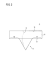
- FIG. 2 is a sectional view showing an ultrasonic flaw detection jig 7.
- the ultrasonic flaw detection jig 7 has a base section 8 and a prominence section 9.
- the base section 8 has a first surface 10 and a second surface 12.
- the first surface 10 is a surface with which a probe is brought into contact.
- the second surface 12 is an opposite surface to the first surface 10 and is a surface which is contact with the main surface 5 of the structure 2.
- the prominence section 9 is provided for the base section 8 to protrude from the second surface 12.
- the prominence section 9 is a portion to be inserted in the countersink 1 in an inspection.
- the prominence section 9 has a conical shape in correspondence to the countersunk section 3.
- the base section 8 includes a flange region 24 disposed to surround the prominence section 9. The flange region 24 is brought into contact with the main surface 5 of the structure 2 in the inspection.
- a contact medium supplying hole 13 is provided for the base section 8.
- the contact medium supplying hole 13 is provided to supply the contact medium to an interface between the prominence section 9 and the wall of the countersunk section 3.
- the contact medium supplying hole 13 is provided to pass through the base section 8.
- One end of the contact medium supplying hole 13 is connected with the first surface 10 and the other end thereof is connected with the surface of the prominence section 9.
- the structure 2 is a composite material, for example, a resin material and so on are used as the material of the base section 8 and the prominence section 9, and an epoxy resin, a polyester resin and so on are desirably used.
- FIG. 3 is a diagram schematically showing the ultrasonic flaw detection method.
- the ultrasonic flaw detection jig 7 is arranged on the main surface 5 of the structure 2. At this time, the ultrasonic flaw detection jig 7 is arranged for the prominence section 9 to be inserted in the countersink 1.
- the prominence section 9 has a conical shape and corresponds to the shape of the countersunk section 3. Therefore, the wall 14 of the countersunk section 3 is covered with the prominence section 9. Also, the base section 8 is brought into contact with the main surface 5 in the flange region 24.
- the contact medium e.g. water
- the contact medium is supplied to the interface between the prominence section 9 and wall 14 through the contact medium supplying hole 13.
- the contact medium is supplied to the contact medium supplying hole 13 from an injector (not shown).
- the probe 16 of an ultrasonic inspection apparatus 15 is brought into contact with the first surface 10. Ultrasonic wave is emitted to and hit against the wall 14 through the ultrasonic flaw detection jig 7 from the probe 16.
- the ultrasonic inspection apparatus 15 detects the reflected wave from the wall 14 by the probe 16, and determines the existence or non-existence of a flaw of the wall 14 based on the detection result. That is, the wall 14 is inspected and the countersink 1 is inspected by the ultrasonic inspection.
- the ultrasonic flaw detection jig 7 is removed from the countersink 1, and the removed ultrasonic flaw detection jig 7 is installed in another countersink 22.
- the ultrasonic flaw detection is carried out for the other countersink 22, like the countersink 1.
- the prominence section 9 corresponds to the whole shape of the countersink 1
- the prominence section 9 does not conform to the other countersink 22.
- the prominence section 9 does not have the shape corresponding to the whole countersink 1 and has a conical shape. If the wall inclination of the countersunk section 3 is the same between the countersink 1 and the other countersink 22, the prominence section 9 fits to the wall of the other countersink 22. It is not necessary to prepare the ultrasonic flaw detection jig 7 for every countersink. Even when a plurality of countersinks with different hole diameters exist, it is possible to inspect them by using the ultrasonic flaw detection jig 7.
- the contact medium supplying hole 13 is provided in the ultrasonic flaw detection jig 7.
- the main surface 5 sometimes is a ceiling surface.
- the contact medium with a high fluidity e.g. water
- the contact medium flows out immediately.
- a medium must be adopted so as to adhere to the wall 14 as the contact medium to prevent the medium from flowing out.
- the wall 14 must be washed after the inspection. There is a case that it is not possible to wash the wall 14, depending on a kind of the structure 2 and the application of the countersink 1.
- the contact medium is supplied through the contact medium supplying hole 13
- the contact medium can be stably supplied to the wall 14 of the countersunk section 3 even if a medium (e.g. water) flowing out immediately is used as the contact medium. Because the water and so on can be used as the contact medium, it is not necessary to wash the structure 2 after the inspection.
- a medium e.g. water
- the flange region 24 is provided. Because the flange region 24 is provided, a worker can treat the ultrasonic flaw detection jig 7 by having the flange region 24. That is, the handling can be improved. In addition, in the flange region 24, the base section 8 functions as a delay material. Therefore, it is possible to make it easier to inspect.
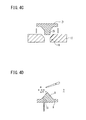
- FIG. 4A to FIG. 4D are diagrams schematically showing a method of manufacturing the ultrasonic flaw detection jig 7.
- a mold member 17 is prepared.
- a countersink 18 has been formed in the mold member 17 to have a shape corresponding to a countersink as an inspection object.
- a side wall member 20 is arranged on the mold member 17 to surround the countersink 18.
- a mold is configured from the countersink 18 and the side wall member 20.
- a mold releasing agent e.g. petrolatum
- a resin material 19 is supplied into the mold.
- the resin material 19 is hardened.
- the mold member 17 is set in a heating apparatus (oven and so on) and is heated.
- the resin material 19 is hardened through the heating.
- the resin material 21 is removed from the mold member 17, as shown in FIG. 4C .
- the resin material 21 has a tip section 25 of the shape corresponding to the countersink 18.
- the resin material 21 is processed. Specifically, the tip section 25 is processed to have a conical shape by using a file and so on, and the prominence section 9 is completed. Also, the contact medium supplying hole 13 is formed by using a drill and so on.
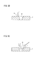
- FIG. 5A to FIG. 5E are diagrams schematically showing the ultrasonic flaw detection method according to the comparison example.
- the resin material 23 is directly injected into the countersink 1 (the inspection object hole) provided for the structure 2 as the inspection object.
- the injected resin material 23 is hardened, as shown in FIG. 5B .
- the structure 2 is of a large-size, the structure 2 cannot be arranged in the heating apparatus such as the oven. Therefore, the injected resin material 23 is hardened at the normal temperature.
- the resin material 23 is processed such that the main surface 5 becomes flat, as shown in FIG. 5C .
- the probe 16 is brought into contact with the surface of the resin material 23 to carry out an inspection by the ultrasonic inspection.
- the resin material 23 is scraped off from the countersink 1.
- the resin material 23 cannot be applied to another countersink because it is scraped off.
- the mold member 17 is used upon the manufacturing.
- the mold member 17 can be made smaller in size than the structure 2, and can be made small to a degree that it can be arranged in the heating apparatus. Therefore, in case of the hardening, the resin material 19 can be heated. As a result, the resin material 19 can be hardened in a short time. For example, when the resin material is used which is hardened by leaving for 8 hours at the normal temperature, it becomes possible to harden by heating for 30 minutes to 1 hour at 60 °C.
- the resin material 23 is directly injected into the countersink 1 as the inspection object. Therefore, it is difficult to carry out the mold release processing beforehand. This is because there is a case that the applied mold releasing material cannot be removed from the countersink 1 when the mold releasing material (petrolatum and so on) is applied.
- the mold member 17 because the mold member 17 is used, the mold release processing can be easily carried out. Therefore, the ultrasonic flaw detection jig 7 can be removed from the mold member 17.
- the ultrasonic flaw detection jig 7 can be removed from the countersink 1. That is, unlike the comparison example, it is not necessary to scrape off the resin material 19. Therefore, the ultrasonic flaw detection jig 7 can be applied to another countersink 22. That is, the present embodiment is more favorable from the point that it is possible to reuse, compared with the comparison example.
- the inspection object is the composite material which is used for the fuselage of the aircraft.
- the inspection object hole is a hole for the fastener insertion has been described.
- the inspection object and the inspection object hole are not limited to them and the present invention can be applied to another use if the inspection object hole has the countersunk section 3 and the connection section 4.
Landscapes
- Physics & Mathematics (AREA)
- Health & Medical Sciences (AREA)
- Life Sciences & Earth Sciences (AREA)
- Chemical & Material Sciences (AREA)
- Analytical Chemistry (AREA)
- Biochemistry (AREA)
- General Health & Medical Sciences (AREA)
- General Physics & Mathematics (AREA)
- Immunology (AREA)
- Pathology (AREA)
- Acoustics & Sound (AREA)
- Investigating Or Analyzing Materials By The Use Of Ultrasonic Waves (AREA)
Abstract
Description
- The present invention relates to an ultrasonic flaw detection jig, an ultrasonic flaw detection method and a method of manufacturing an ultrasonic flaw detection jig.
- Regarding a non-destructive inspection technique, an ultrasonic inspection is known.
- An ultrasonic inspection technique is disclosed in Patent Literature 1 (
JP H09-1133664A Patent Literature 1 discloses covering an inspection surface of a non-inspection object with waveguide substance whose acoustic impedance value is equal to or approximate to that of the non-inspection object so that the inspection surface of the non-inspection object becomes flat. Also,Patent Literature 1 discloses that a waveguide is removed from the inspection object and attached to another inspection object (reference to para. 0021). - [Patent Literature 1]
JP H09-1133664A - By the way, a countersink is sometimes provided for a structure.
FIG. 1 is a sectional view schematically showing astructure 2 in which acountersink 1 is formed. As shown inFIG. 1 , thestructure 2 includes amain surface 5 and arear surface 6. Thecountersink 1 is formed to pass through thestructure 2 between themain surface 5 and therear surface 6. Thecountersink 1 has a countersunk section 3 and a connection section 4. The countersunk section 3 is connected with themain surface 5 at its one end and extends from themain surface 5 toward therear surface 6 while reducing the diameter. The connection section 4 connects the bottom of the countersunk section 3 and therear surface 6. The diameter of the connection section 4 is constant. - When the
countersink 1 is formed in thestructure 2, a flaw is sometimes formed on the wall of the countersunk section 3 and the connection section 4. Therefore, after thecountersink 1 is formed, thecountersink 1 is inspected. - The inventors of the present invention are considering use of the ultrasonic inspection, to inspect whether a flaw exists in the countersunk section 3 and the connection section 4. When the ultrasonic inspection is carried out, the
countersink 1 is buried with a waveguide material (ultrasonic flaw detection jig) to lead the ultrasonic into the wall of the countersunk section 3. After that, the ultrasonic is emitted to the structure through the waveguide material and the wall of the countersunk section 3 from the probe to determine whether the existence or non-existence of the flaw is determine based on the reflected wave. -
Many countersinks 1 are sometimes formed in thestructure 2. In such a case, there would be a case to apply the waveguide material which has been applied to onecountersink 1, to anothercountersink 1, to be described inPatent Literature 1. However, the hole diameter would be different among thecountersinks 1, due to a manufacturing error. Also, the hole diameter is different for reasons in case of design. When the hole diameter is different, the waveguide material does not fit with theother countersink 1. Thus, the waveguide material has to be prepared for everycountersink 1 so that great labor is spent to inspect all thecountersinks 1. - Therefore, an object of the present invention is to provide an ultrasonic flaw detection jig, by which inspection can be made easily even when the hole diameter is different.
- The ultrasonic flaw detection jig according to the present invention includes a base section with which a probe of an ultrasonic inspection apparatus is brought into contact; and a prominence section provided for the base section and inserted into an inspection object hole of an inspection object. The inspection object hole has a countersunk section connected with a main surface of the inspection object and extending from the main surface while reducing a diameter, and a connection section which connects the bottom of the countersunk section and a rear surface of the inspection object. The prominence section has a conical shape corresponding to the shape of the countersunk section.
- An ultrasonic flaw detection method according to the present invention includes arranging an ultrasonic flaw detection jig on a main surface of an inspection object having an inspection object hole; and inspecting an inspection object hole by bringing a probe of an ultrasonic inspection apparatus into contact with an ultrasonic flaw detection jig after the arranging. The ultrasonic flaw detection jig includes a base section and a prominence section provided for the base section and inserted into the inspection object hole. The inspection object hole has a countersunk section connected with the main surface at its one end, and extending from the main surface while reducing a diameter, and a connection section connecting a bottom of the countersunk section and a rear surface of the inspection object. The prominence section has a conical shape corresponding to the shape of the countersunk section. The arranging includes arranging the ultrasonic flaw detection jig so that the prominence section is inserted into the inspection object hole.
- An ultrasonic flaw detection jig which is manufactured by a manufacturing method according to the present invention includes a base section with which a probe of an ultrasonic inspection apparatus is brought into contact; and a prominence section provided for the base section and inserted into an inspection object hole of the inspection object. The inspection object hole has a countersunk section connected with a main surface of the inspection object at its one end and extending from the main surface while reducing a diameter, and a connection section connecting a bottom of the countersunk section and a rear surface of the inspection object. The prominence section has a conical shape corresponding to the shape of the countersunk section. The method of manufacturing the ultrasonic flaw detection jig includes supplying a resin material to a mold of a mold member; hardening the supplied resin material; removing the hardened resin material from the mold; and shaping the removed resin material to obtain the ultrasonic flaw detection jig.
- According to the present invention, the ultrasonic flaw detection jig can be provided, by which the inspection can be made easily even when the hole diameter is different.
-
-
FIG. 1 is a sectional view schematically showing a structure in which a countersink is provided. -
FIG. 2 is a sectional view showing an ultrasonic flaw detection jig. -
FIG. 3 is a diagram schematically showing an ultrasonic flaw detection method. -
FIG. 4A is a diagram schematically showing a method of manufacturing the ultrasonic flaw detection jig. -
FIG. 4B is a diagram schematically showing the method of manufacturing the ultrasonic flaw detection jig. -
FIG. 4C is a diagram schematically showing the method of manufacturing the ultrasonic flaw detection jig. -
FIG. 4D is a diagram schematically showing the method of manufacturing the ultrasonic flaw detection jig. -
FIG. 5A is a diagram schematically showing the ultrasonic flaw detection method according to a comparison example. -
FIG. 5B is a diagram schematically showing the ultrasonic flaw detection method according to the comparison example. -
FIG. 5C is a diagram schematically showing the ultrasonic flaw detection method according to the comparison example. -
FIG. 5D is a diagram schematically showing the ultrasonic flaw detection method according to the comparison example. -
FIG. 5E is a diagram schematically showing the ultrasonic flaw detection method according to the comparison example. - Hereinafter, an ultrasonic flaw detection jig according to embodiments of the present invention will be described with reference to the attached drawings.
- First, an inspection object will be described. The ultrasonic flaw detection jig according to the present embodiment is used to inspect a countersink 1 (an inspection object hole) provided for a structure 2 (an inspection object) as shown in
FIG. 1 . That is, thecountersink 1 passes through thestructure 2 between themain surface 5 and theback surface 6 and has a countersunk section 3 and a connection section 4. Note that the section shape of thecountersink 1 in the plane which is parallel to themain surface 5 is circular. - In the present embodiment, the
structure 2 is assumed to be a composite material (fiber-reinforced composite material) which is used for the fuselage of an aircraft. Also, thecountersink 1 is assumed to be a hole for a fastener to be inserted. - Next, the ultrasonic
flaw detection jig 7 will be described.FIG. 2 is a sectional view showing an ultrasonicflaw detection jig 7. - As shown in FIG. 7, the ultrasonic
flaw detection jig 7 has abase section 8 and aprominence section 9. - The
base section 8 has afirst surface 10 and asecond surface 12. Thefirst surface 10 is a surface with which a probe is brought into contact. Thesecond surface 12 is an opposite surface to thefirst surface 10 and is a surface which is contact with themain surface 5 of thestructure 2. - The
prominence section 9 is provided for thebase section 8 to protrude from thesecond surface 12. Theprominence section 9 is a portion to be inserted in thecountersink 1 in an inspection. Theprominence section 9 has a conical shape in correspondence to the countersunk section 3. - Also, the
base section 8 includes aflange region 24 disposed to surround theprominence section 9. Theflange region 24 is brought into contact with themain surface 5 of thestructure 2 in the inspection. - Moreover, a contact
medium supplying hole 13 is provided for thebase section 8. The contactmedium supplying hole 13 is provided to supply the contact medium to an interface between theprominence section 9 and the wall of the countersunk section 3. The contactmedium supplying hole 13 is provided to pass through thebase section 8. One end of the contactmedium supplying hole 13 is connected with thefirst surface 10 and the other end thereof is connected with the surface of theprominence section 9. - When the
structure 2 is a composite material, for example, a resin material and so on are used as the material of thebase section 8 and theprominence section 9, and an epoxy resin, a polyester resin and so on are desirably used. - Next, an ultrasonic flaw detection method will be described.
FIG. 3 is a diagram schematically showing the ultrasonic flaw detection method. - First, the ultrasonic
flaw detection jig 7 is arranged on themain surface 5 of thestructure 2. At this time, the ultrasonicflaw detection jig 7 is arranged for theprominence section 9 to be inserted in thecountersink 1. Here, theprominence section 9 has a conical shape and corresponds to the shape of the countersunk section 3. Therefore, the wall 14 of the countersunk section 3 is covered with theprominence section 9. Also, thebase section 8 is brought into contact with themain surface 5 in theflange region 24. - Next, the contact medium (e.g. water) is supplied to the interface between the
prominence section 9 and wall 14 through the contactmedium supplying hole 13. For example, the contact medium is supplied to the contactmedium supplying hole 13 from an injector (not shown). - Moreover, the
probe 16 of anultrasonic inspection apparatus 15 is brought into contact with thefirst surface 10. Ultrasonic wave is emitted to and hit against the wall 14 through the ultrasonicflaw detection jig 7 from theprobe 16. Theultrasonic inspection apparatus 15 detects the reflected wave from the wall 14 by theprobe 16, and determines the existence or non-existence of a flaw of the wall 14 based on the detection result. That is, the wall 14 is inspected and thecountersink 1 is inspected by the ultrasonic inspection. - After the inspection ends, the ultrasonic
flaw detection jig 7 is removed from thecountersink 1, and the removed ultrasonicflaw detection jig 7 is installed in anothercountersink 22. Thus, the ultrasonic flaw detection is carried out for theother countersink 22, like thecountersink 1. - Here, there is a case that the size (a hole diameter) of the
other countersink 22 is different from that of thecountersink 1 due to a manufacturing error and a reason in case of the design. When theprominence section 9 corresponds to the whole shape of thecountersink 1, there is a case that theprominence section 9 does not conform to theother countersink 22. However, in the present embodiment, theprominence section 9 does not have the shape corresponding to thewhole countersink 1 and has a conical shape. If the wall inclination of the countersunk section 3 is the same between thecountersink 1 and theother countersink 22, theprominence section 9 fits to the wall of theother countersink 22. It is not necessary to prepare the ultrasonicflaw detection jig 7 for every countersink. Even when a plurality of countersinks with different hole diameters exist, it is possible to inspect them by using the ultrasonicflaw detection jig 7. - Also, in the present embodiment, the contact
medium supplying hole 13 is provided in the ultrasonicflaw detection jig 7. For example, themain surface 5 sometimes is a ceiling surface. In such a case, when the contact medium with a high fluidity (e.g. water) is merely supplied to the wall 14 of the countersunk section 3, the contact medium flows out immediately. A medium must be adopted so as to adhere to the wall 14 as the contact medium to prevent the medium from flowing out. When the contact medium adhering to the wall 14 is used, the wall 14 must be washed after the inspection. There is a case that it is not possible to wash the wall 14, depending on a kind of thestructure 2 and the application of thecountersink 1. On the other hand, in the present embodiment, because the contact medium is supplied through the contactmedium supplying hole 13, the contact medium can be stably supplied to the wall 14 of the countersunk section 3 even if a medium (e.g. water) flowing out immediately is used as the contact medium. Because the water and so on can be used as the contact medium, it is not necessary to wash thestructure 2 after the inspection. - Moreover, according to the present embodiment, the
flange region 24 is provided. Because theflange region 24 is provided, a worker can treat the ultrasonicflaw detection jig 7 by having theflange region 24. That is, the handling can be improved. In addition, in theflange region 24, thebase section 8 functions as a delay material. Therefore, it is possible to make it easier to inspect. - Next, an example of a method of manufacturing the ultrasonic
flaw detection jig 7 according to the present embodiment will be described.FIG. 4A to FIG. 4D are diagrams schematically showing a method of manufacturing the ultrasonicflaw detection jig 7. - First, as shown in
FIG. 4A , amold member 17 is prepared. Acountersink 18 has been formed in themold member 17 to have a shape corresponding to a countersink as an inspection object. Aside wall member 20 is arranged on themold member 17 to surround thecountersink 18. A mold is configured from thecountersink 18 and theside wall member 20. A mold releasing agent (e.g. petrolatum) (not shown) is applied onto the mold side walls (side walls of thecountersink 18 and the side wall member 20). After that, aresin material 19 is supplied into the mold. As theresin material 19, a material of a heat hardening type is used. - Next, as shown in
FIG. 4B , theresin material 19 is hardened. Specifically, themold member 17 is set in a heating apparatus (oven and so on) and is heated. Theresin material 19 is hardened through the heating. - Next, the
hardened resin material 21 is removed from themold member 17, as shown inFIG. 4C . Theresin material 21 has atip section 25 of the shape corresponding to thecountersink 18. - Next, as shown in
FIG. 4D , theresin material 21 is processed. Specifically, thetip section 25 is processed to have a conical shape by using a file and so on, and theprominence section 9 is completed. Also, the contactmedium supplying hole 13 is formed by using a drill and so on. - In the above, the ultrasonic
flaw detection jig 7 is obtained. - Next, by comparing the present embodiment with a comparison example, the operation effect of the present embodiment will be described.
FIG. 5A to FIG. 5E are diagrams schematically showing the ultrasonic flaw detection method according to the comparison example. - As shown in
FIG. 5A , in the comparison example, theresin material 23 is directly injected into the countersink 1 (the inspection object hole) provided for thestructure 2 as the inspection object. - Next, the injected
resin material 23 is hardened, as shown inFIG. 5B . At this time, if thestructure 2 is of a large-size, thestructure 2 cannot be arranged in the heating apparatus such as the oven. Therefore, the injectedresin material 23 is hardened at the normal temperature. - Next, the
resin material 23 is processed such that themain surface 5 becomes flat, as shown inFIG. 5C . - Next, as shown in
FIG. 5D , theprobe 16 is brought into contact with the surface of theresin material 23 to carry out an inspection by the ultrasonic inspection. - After the inspection, as shown in
FIG. 5E , theresin material 23 is scraped off from thecountersink 1. Theresin material 23 cannot be applied to another countersink because it is scraped off. - Compared with the above-mentioned comparison example, in the present embodiment, the
mold member 17 is used upon the manufacturing. Themold member 17 can be made smaller in size than thestructure 2, and can be made small to a degree that it can be arranged in the heating apparatus. Therefore, in case of the hardening, theresin material 19 can be heated. As a result, theresin material 19 can be hardened in a short time. For example, when the resin material is used which is hardened by leaving for 8 hours at the normal temperature, it becomes possible to harden by heating for 30 minutes to 1 hour at 60 °C. - Also, in the comparison example, the
resin material 23 is directly injected into thecountersink 1 as the inspection object. Therefore, it is difficult to carry out the mold release processing beforehand. This is because there is a case that the applied mold releasing material cannot be removed from thecountersink 1 when the mold releasing material (petrolatum and so on) is applied. On the other hand, in the present embodiment, because themold member 17 is used, the mold release processing can be easily carried out. Therefore, the ultrasonicflaw detection jig 7 can be removed from themold member 17. - In the present embodiment, because the mold release processing can be carried out, the ultrasonic
flaw detection jig 7 can be removed from thecountersink 1. That is, unlike the comparison example, it is not necessary to scrape off theresin material 19. Therefore, the ultrasonicflaw detection jig 7 can be applied to anothercountersink 22. That is, the present embodiment is more favorable from the point that it is possible to reuse, compared with the comparison example. - Note that in the embodiment, a case that the inspection object is the composite material which is used for the fuselage of the aircraft has been described. Also, a case that the inspection object hole is a hole for the fastener insertion has been described. However, the inspection object and the inspection object hole are not limited to them and the present invention can be applied to another use if the inspection object hole has the countersunk section 3 and the connection section 4.
- The present application is based on Japanese Patent Application No.
JP 2013-018618
Claims (10)
- An ultrasonic flaw detection jig comprising:a base section with which a probe of an ultrasonic inspection apparatus is brought into contact; anda prominence section provided for the base section and inserted into an inspection object hole formed in an inspection object,wherein the inspection object hole comprises:a countersunk section connected with a main surface of the inspection object and extending from the main surface while decreasing a diameter; anda connection section configured to connect a bottom of the countersunk section and a rear surface of the inspection object, andwherein the prominence section has a conical shape corresponding to a shape of the countersunk section.
- The ultrasonic flaw detection jig according to claim 1, wherein the base section is provided with a contact medium supply hole to pass through the base section and to be connected with a surface of the prominence section at its one end.
- The ultrasonic flaw detection jig according to claim 1 or 2, wherein the base section has:a first surface with which the probe is brought into contact; anda second surface provided to oppose to the first surface, andwherein the prominence section is provided on the second surface.
- The ultrasonic flaw detection jig according to claim 3, further comprising:a flange region disposed for the base section to contact the main surface of the inspection object and to surround the prominence section.
- An ultrasonic flaw detection method comprising:arranging an ultrasonic flaw detection jig on a main surface of an inspection object having an inspection object hole;inspecting the inspection object hole by bring a probe of an ultrasonic inspection apparatus into contact with an ultrasonic flaw detection jig, after the arranging,wherein an ultrasonic flaw detection jig comprises:a base section; anda prominence section provided for the base section and inserted into an inspection object hole,wherein the inspection object hole comprises:a countersunk section connected with a main surface at its one end and extending from the main surface for a diameter to reduce; anda connection section connecting a bottom of the countersunk section and a rear surface of the inspection object,wherein the prominence section has a conical shape corresponding to the shape of the countersunk section,wherein the arranging comprises:arranging the ultrasonic flaw detection jig such that the prominence section is inserted in the inspection object hole.
- The ultrasonic flaw detection method according to claim 5, wherein the base section comprises a contact medium supply hole configured to pass through the base section and to be connected with a surface of the prominence section,
wherein the inspecting further comprises:supplying a contact medium to an interface between the prominence section and a wall surface of the countersunk section through the contact medium supply hole. - The ultrasonic flaw detection method according to claim 5 or 6, wherein the inspection object is a fiber reinforced composite material.
- A method of manufacturing an ultrasonic flaw detection jig, which comprises:a base section with which a probe of an ultrasonic inspection apparatus is brought into contact; anda prominence section provided for the base section and inserted into an inspection object hole of an inspection object,wherein the inspection object hole comprises:a countersunk section connected with a main surface of the inspection object and extending from the main surface while reducing a diameter; anda connection section connecting a bottom of the countersunk section and the rear surface of the inspection object, andwherein the prominence section has a conical shape corresponding to a shape of the countersunk section,said method of manufacturing the ultrasonic flaw detection jig comprises:supplying a resin material to a mold of a mold member;hardening the supplied resin material;removing the hardened resin material from the mold; andshaping the removed resin material for an ultrasonic flaw detection jig.
- The method of manufacturing the ultrasonic flaw detection jig according to claim 8, wherein said supplying the resin material comprises:supplying thermosetting resin material as the resin material,wherein said hardening comprises:heating the mold member.
- The method of manufacturing the ultrasonic flaw detection jig according to claim 8 or 9, wherein said shaping comprises:forming a contact medium supply hole in the base section so as to be connected with a surface of the prominence section at its one end.
Applications Claiming Priority (2)
| Application Number | Priority Date | Filing Date | Title |
|---|---|---|---|
| JP2013018618A JP6252825B2 (en) | 2013-02-01 | 2013-02-01 | Ultrasonic flaw detection jig, ultrasonic flaw detection method, and method for manufacturing ultrasonic flaw detection jig |
| PCT/JP2014/051189 WO2014119436A1 (en) | 2013-02-01 | 2014-01-22 | Ultrasonic flaw detection jig, ultrasonic flaw detection method, and manufacturing method for ultrasonic flaw detection jig |
Publications (2)
| Publication Number | Publication Date |
|---|---|
| EP2952891A1 true EP2952891A1 (en) | 2015-12-09 |
| EP2952891A4 EP2952891A4 (en) | 2016-09-28 |
Family
ID=51262150
Family Applications (1)
| Application Number | Title | Priority Date | Filing Date |
|---|---|---|---|
| EP14746359.0A Withdrawn EP2952891A4 (en) | 2013-02-01 | 2014-01-22 | Ultrasonic flaw detection jig, ultrasonic flaw detection method, and manufacturing method for ultrasonic flaw detection jig |
Country Status (5)
| Country | Link |
|---|---|
| US (1) | US10067098B2 (en) |
| EP (1) | EP2952891A4 (en) |
| JP (1) | JP6252825B2 (en) |
| CN (1) | CN104956219A (en) |
| WO (1) | WO2014119436A1 (en) |
Families Citing this family (4)
| Publication number | Priority date | Publication date | Assignee | Title |
|---|---|---|---|---|
| JP6599279B2 (en) * | 2016-04-14 | 2019-10-30 | 三菱重工業株式会社 | Ultrasonic inspection jig and ultrasonic inspection method |
| US10267771B2 (en) * | 2016-04-22 | 2019-04-23 | Airbus Operations Sas | Method for testing a structural component of a vehicle |
| JP7548501B2 (en) * | 2020-09-16 | 2024-09-10 | 大阪瓦斯株式会社 | Ultrasonic Inspection Method |
| CN112964792B (en) * | 2021-02-01 | 2024-06-25 | 太原重工轨道交通设备有限公司 | Ultrasonic detection calibration test block and detection method for wheel rim |
Family Cites Families (14)
| Publication number | Priority date | Publication date | Assignee | Title |
|---|---|---|---|---|
| JPS471117Y1 (en) * | 1967-01-24 | 1972-01-14 | ||
| JPS563660Y2 (en) * | 1977-11-19 | 1981-01-27 | ||
| JPS5892949A (en) * | 1981-11-30 | 1983-06-02 | Nippon Steel Corp | Probing shoe for ultrasonic oblique flaw detecting application |
| DE3633556A1 (en) * | 1985-10-04 | 1987-04-09 | Basf Ag | Device for non destructively testing components made of fibre-reinforced composite materials and other materials having strong ultrasound scattering for very small defects |
| JPS63126859U (en) * | 1987-02-09 | 1988-08-18 | ||
| JPH054010U (en) * | 1991-07-05 | 1993-01-22 | 株式会社トキメツク | Ultrasonic probe |
| JP2541958Y2 (en) * | 1991-10-31 | 1997-07-23 | 川崎製鉄株式会社 | Ultrasonic transducer |
| JPH09133664A (en) | 1995-11-07 | 1997-05-20 | Toyota Motor Corp | Ultrasonic flaw detection method |
| US6668441B1 (en) * | 2000-06-07 | 2003-12-30 | Lockheed Martin Corporation | Screw mounting installation method |
| US8286487B2 (en) * | 2009-01-31 | 2012-10-16 | The Boeing Company | Ultrasonic aperture scanning system and method |
| US8869621B2 (en) * | 2009-01-31 | 2014-10-28 | The Boeing Company | Geometry compensating transducer attachments for ultrasonic inspection of chamfers or countersunk surfaces |
| CN101694482A (en) * | 2009-10-22 | 2010-04-14 | 中国第一重型机械股份公司 | Ultrasonic flaw detection auxiliary device and operating method thereof |
| US8914244B2 (en) * | 2010-08-04 | 2014-12-16 | The Boeing Company | Apparatus and method for inspecting laminated structure |
| GB201104409D0 (en) * | 2011-03-16 | 2011-04-27 | Airbus Operations Ltd | Improvements in inspection of composite components |
-
2013
- 2013-02-01 JP JP2013018618A patent/JP6252825B2/en active Active
-
2014
- 2014-01-22 CN CN201480005654.1A patent/CN104956219A/en active Pending
- 2014-01-22 EP EP14746359.0A patent/EP2952891A4/en not_active Withdrawn
- 2014-01-22 WO PCT/JP2014/051189 patent/WO2014119436A1/en not_active Ceased
- 2014-01-22 US US14/763,166 patent/US10067098B2/en active Active
Also Published As
| Publication number | Publication date |
|---|---|
| US10067098B2 (en) | 2018-09-04 |
| EP2952891A4 (en) | 2016-09-28 |
| JP2014149241A (en) | 2014-08-21 |
| JP6252825B2 (en) | 2017-12-27 |
| US20150355146A1 (en) | 2015-12-10 |
| WO2014119436A1 (en) | 2014-08-07 |
| CN104956219A (en) | 2015-09-30 |
Similar Documents
| Publication | Publication Date | Title |
|---|---|---|
| US10067098B2 (en) | Ultrasonic flaw detection jig, ultrasonic flaw detection method and method of manufacturing ultrasonic flaw detection jig | |
| US9441652B2 (en) | Joint assembly and method of assembling the same | |
| CN103492158B (en) | Formed parts | |
| CN107207099B (en) | Aircraft parts positioning device, aircraft assembly system and aircraft assembly method | |
| US9933392B2 (en) | Apparatus, system, and method for non-destructive ultrasonic inspection | |
| Kruse et al. | Bonding of CFRP primary aerospace structures–crackstopping in composite bonded jointsunder fatigue | |
| CN105465142A (en) | High-temperature alloy embedded type self-locking nut assembly and processing method thereof | |
| US10822120B2 (en) | Method and system for connecting two aircraft components from a thermoplastic composite material | |
| JP5265152B2 (en) | Monitoring method of fatigue crack growth in CFRP plate | |
| US5014556A (en) | Acoustic emission simulator | |
| CN105378470A (en) | Device for inspecting the surface of an electrically conductive part | |
| US8286487B2 (en) | Ultrasonic aperture scanning system and method | |
| CN104234942B (en) | Thermal Imaging Inspection System for Composite Wind Turbine Blades | |
| EP2982961B1 (en) | Method for testing the fracture toughness of an adhesive joint to be formed | |
| US20230288918A1 (en) | Outlier detection and management | |
| CN110763559A (en) | In-situ monitoring device and method for energy signal of fracture behavior of C/SiC composite fasteners | |
| JP6016589B2 (en) | Structure and method for detecting peeling of structure | |
| US8499631B2 (en) | Nondestructive inspection of aircraft stiffeners | |
| WO2008105849A2 (en) | Methods and apparatus for aircraft structural length of service enhancement | |
| EP3084384B1 (en) | Assessing integrity of bonded joints | |
| Pederbelli et al. | Effects of singular and non‐singular stress fields on very high cycle fatigue life of adhesive joints | |
| JP6029320B2 (en) | Shape correction transducer connection mechanism for ultrasonic inspection of chamfered part or dish surface | |
| Stepanova et al. | Acoustic-emission testing of multiple-pass welding defects of large-size constructions | |
| Bing et al. | Evaluating Effectiveness in Bonded Repair Techniques for Aircraft Structures using Finite Element Simulations | |
| US10406764B2 (en) | Method for repairing a composite part |
Legal Events
| Date | Code | Title | Description |
|---|---|---|---|
| PUAI | Public reference made under article 153(3) epc to a published international application that has entered the european phase |
Free format text: ORIGINAL CODE: 0009012 |
|
| 17P | Request for examination filed |
Effective date: 20150722 |
|
| AK | Designated contracting states |
Kind code of ref document: A1 Designated state(s): AL AT BE BG CH CY CZ DE DK EE ES FI FR GB GR HR HU IE IS IT LI LT LU LV MC MK MT NL NO PL PT RO RS SE SI SK SM TR |
|
| AX | Request for extension of the european patent |
Extension state: BA ME |
|
| DAX | Request for extension of the european patent (deleted) | ||
| A4 | Supplementary search report drawn up and despatched |
Effective date: 20160826 |
|
| RIC1 | Information provided on ipc code assigned before grant |
Ipc: G01N 29/22 20060101ALI20160822BHEP Ipc: G01N 29/28 20060101AFI20160822BHEP |
|
| STAA | Information on the status of an ep patent application or granted ep patent |
Free format text: STATUS: EXAMINATION IS IN PROGRESS |
|
| 17Q | First examination report despatched |
Effective date: 20200423 |
|
| GRAP | Despatch of communication of intention to grant a patent |
Free format text: ORIGINAL CODE: EPIDOSNIGR1 |
|
| STAA | Information on the status of an ep patent application or granted ep patent |
Free format text: STATUS: GRANT OF PATENT IS INTENDED |
|
| INTG | Intention to grant announced |
Effective date: 20201221 |
|
| STAA | Information on the status of an ep patent application or granted ep patent |
Free format text: STATUS: THE APPLICATION IS DEEMED TO BE WITHDRAWN |
|
| 18D | Application deemed to be withdrawn |
Effective date: 20210501 |