EP2952747A1 - Compressor system with resonator - Google Patents
Compressor system with resonator Download PDFInfo
- Publication number
- EP2952747A1 EP2952747A1 EP15170228.9A EP15170228A EP2952747A1 EP 2952747 A1 EP2952747 A1 EP 2952747A1 EP 15170228 A EP15170228 A EP 15170228A EP 2952747 A1 EP2952747 A1 EP 2952747A1
- Authority
- EP
- European Patent Office
- Prior art keywords
- resonators
- compressor
- annular ring
- resonator
- discharge pipe
- Prior art date
- Legal status (The legal status is an assumption and is not a legal conclusion. Google has not performed a legal analysis and makes no representation as to the accuracy of the status listed.)
- Granted
Links
Images



Classifications
-
- F—MECHANICAL ENGINEERING; LIGHTING; HEATING; WEAPONS; BLASTING
- F04—POSITIVE - DISPLACEMENT MACHINES FOR LIQUIDS; PUMPS FOR LIQUIDS OR ELASTIC FLUIDS
- F04C—ROTARY-PISTON, OR OSCILLATING-PISTON, POSITIVE-DISPLACEMENT MACHINES FOR LIQUIDS; ROTARY-PISTON, OR OSCILLATING-PISTON, POSITIVE-DISPLACEMENT PUMPS
- F04C29/00—Component parts, details or accessories of pumps or pumping installations, not provided for in groups F04C18/00 - F04C28/00
- F04C29/06—Silencing
- F04C29/065—Noise dampening volumes, e.g. muffler chambers
-
- F—MECHANICAL ENGINEERING; LIGHTING; HEATING; WEAPONS; BLASTING
- F04—POSITIVE - DISPLACEMENT MACHINES FOR LIQUIDS; PUMPS FOR LIQUIDS OR ELASTIC FLUIDS
- F04B—POSITIVE-DISPLACEMENT MACHINES FOR LIQUIDS; PUMPS
- F04B39/00—Component parts, details, or accessories, of pumps or pumping systems specially adapted for elastic fluids, not otherwise provided for in, or of interest apart from, groups F04B25/00 - F04B37/00
- F04B39/0027—Pulsation and noise damping means
-
- F—MECHANICAL ENGINEERING; LIGHTING; HEATING; WEAPONS; BLASTING
- F04—POSITIVE - DISPLACEMENT MACHINES FOR LIQUIDS; PUMPS FOR LIQUIDS OR ELASTIC FLUIDS
- F04C—ROTARY-PISTON, OR OSCILLATING-PISTON, POSITIVE-DISPLACEMENT MACHINES FOR LIQUIDS; ROTARY-PISTON, OR OSCILLATING-PISTON, POSITIVE-DISPLACEMENT PUMPS
- F04C15/00—Component parts, details or accessories of machines, pumps or pumping installations, not provided for in groups F04C2/00 - F04C14/00
- F04C15/0042—Systems for the equilibration of forces acting on the machines or pump
- F04C15/0049—Equalization of pressure pulses
-
- F—MECHANICAL ENGINEERING; LIGHTING; HEATING; WEAPONS; BLASTING
- F04—POSITIVE - DISPLACEMENT MACHINES FOR LIQUIDS; PUMPS FOR LIQUIDS OR ELASTIC FLUIDS
- F04C—ROTARY-PISTON, OR OSCILLATING-PISTON, POSITIVE-DISPLACEMENT MACHINES FOR LIQUIDS; ROTARY-PISTON, OR OSCILLATING-PISTON, POSITIVE-DISPLACEMENT PUMPS
- F04C18/00—Rotary-piston pumps specially adapted for elastic fluids
- F04C18/08—Rotary-piston pumps specially adapted for elastic fluids of intermeshing-engagement type, i.e. with engagement of co-operating members similar to that of toothed gearing
- F04C18/10—Rotary-piston pumps specially adapted for elastic fluids of intermeshing-engagement type, i.e. with engagement of co-operating members similar to that of toothed gearing of internal-axis type with the outer member having more teeth or tooth equivalents, e.g. rollers, than the inner member
-
- F—MECHANICAL ENGINEERING; LIGHTING; HEATING; WEAPONS; BLASTING
- F04—POSITIVE - DISPLACEMENT MACHINES FOR LIQUIDS; PUMPS FOR LIQUIDS OR ELASTIC FLUIDS
- F04C—ROTARY-PISTON, OR OSCILLATING-PISTON, POSITIVE-DISPLACEMENT MACHINES FOR LIQUIDS; ROTARY-PISTON, OR OSCILLATING-PISTON, POSITIVE-DISPLACEMENT PUMPS
- F04C18/00—Rotary-piston pumps specially adapted for elastic fluids
- F04C18/08—Rotary-piston pumps specially adapted for elastic fluids of intermeshing-engagement type, i.e. with engagement of co-operating members similar to that of toothed gearing
- F04C18/12—Rotary-piston pumps specially adapted for elastic fluids of intermeshing-engagement type, i.e. with engagement of co-operating members similar to that of toothed gearing of other than internal-axis type
- F04C18/14—Rotary-piston pumps specially adapted for elastic fluids of intermeshing-engagement type, i.e. with engagement of co-operating members similar to that of toothed gearing of other than internal-axis type with toothed rotary pistons
- F04C18/16—Rotary-piston pumps specially adapted for elastic fluids of intermeshing-engagement type, i.e. with engagement of co-operating members similar to that of toothed gearing of other than internal-axis type with toothed rotary pistons with helical teeth, e.g. chevron-shaped, screw type
-
- F—MECHANICAL ENGINEERING; LIGHTING; HEATING; WEAPONS; BLASTING
- F04—POSITIVE - DISPLACEMENT MACHINES FOR LIQUIDS; PUMPS FOR LIQUIDS OR ELASTIC FLUIDS
- F04C—ROTARY-PISTON, OR OSCILLATING-PISTON, POSITIVE-DISPLACEMENT MACHINES FOR LIQUIDS; ROTARY-PISTON, OR OSCILLATING-PISTON, POSITIVE-DISPLACEMENT PUMPS
- F04C2/00—Rotary-piston machines or pumps
- F04C2/08—Rotary-piston machines or pumps of intermeshing-engagement type, i.e. with engagement of co-operating members similar to that of toothed gearing
- F04C2/12—Rotary-piston machines or pumps of intermeshing-engagement type, i.e. with engagement of co-operating members similar to that of toothed gearing of other than internal-axis type
- F04C2/14—Rotary-piston machines or pumps of intermeshing-engagement type, i.e. with engagement of co-operating members similar to that of toothed gearing of other than internal-axis type with toothed rotary pistons
- F04C2/16—Rotary-piston machines or pumps of intermeshing-engagement type, i.e. with engagement of co-operating members similar to that of toothed gearing of other than internal-axis type with toothed rotary pistons with helical teeth, e.g. chevron-shaped, screw type
-
- F—MECHANICAL ENGINEERING; LIGHTING; HEATING; WEAPONS; BLASTING
- F04—POSITIVE - DISPLACEMENT MACHINES FOR LIQUIDS; PUMPS FOR LIQUIDS OR ELASTIC FLUIDS
- F04C—ROTARY-PISTON, OR OSCILLATING-PISTON, POSITIVE-DISPLACEMENT MACHINES FOR LIQUIDS; ROTARY-PISTON, OR OSCILLATING-PISTON, POSITIVE-DISPLACEMENT PUMPS
- F04C29/00—Component parts, details or accessories of pumps or pumping installations, not provided for in groups F04C18/00 - F04C28/00
- F04C29/06—Silencing
- F04C29/061—Silencers using overlapping frequencies, e.g. Helmholtz resonators
-
- F—MECHANICAL ENGINEERING; LIGHTING; HEATING; WEAPONS; BLASTING
- F04—POSITIVE - DISPLACEMENT MACHINES FOR LIQUIDS; PUMPS FOR LIQUIDS OR ELASTIC FLUIDS
- F04D—NON-POSITIVE-DISPLACEMENT PUMPS
- F04D29/00—Details, component parts, or accessories
- F04D29/66—Combating cavitation, whirls, noise, vibration or the like; Balancing
- F04D29/661—Combating cavitation, whirls, noise, vibration or the like; Balancing especially adapted for elastic fluid pumps
- F04D29/663—Sound attenuation
- F04D29/665—Sound attenuation by means of resonance chambers or interference
-
- F—MECHANICAL ENGINEERING; LIGHTING; HEATING; WEAPONS; BLASTING
- F16—ENGINEERING ELEMENTS AND UNITS; GENERAL MEASURES FOR PRODUCING AND MAINTAINING EFFECTIVE FUNCTIONING OF MACHINES OR INSTALLATIONS; THERMAL INSULATION IN GENERAL
- F16L—PIPES; JOINTS OR FITTINGS FOR PIPES; SUPPORTS FOR PIPES, CABLES OR PROTECTIVE TUBING; MEANS FOR THERMAL INSULATION IN GENERAL
- F16L55/00—Devices or appurtenances for use in, or in connection with, pipes or pipe systems
- F16L55/02—Energy absorbers; Noise absorbers
- F16L55/033—Noise absorbers
-
- F—MECHANICAL ENGINEERING; LIGHTING; HEATING; WEAPONS; BLASTING
- F16—ENGINEERING ELEMENTS AND UNITS; GENERAL MEASURES FOR PRODUCING AND MAINTAINING EFFECTIVE FUNCTIONING OF MACHINES OR INSTALLATIONS; THERMAL INSULATION IN GENERAL
- F16L—PIPES; JOINTS OR FITTINGS FOR PIPES; SUPPORTS FOR PIPES, CABLES OR PROTECTIVE TUBING; MEANS FOR THERMAL INSULATION IN GENERAL
- F16L55/00—Devices or appurtenances for use in, or in connection with, pipes or pipe systems
- F16L55/02—Energy absorbers; Noise absorbers
- F16L55/027—Throttle passages
- F16L55/02781—The regulating element being provided with radial outputs
Definitions
- the present invention relates to compressor systems, and more particularly, to compressor systems with noise reduction.
- a compressor system in one form, includes a compressor, and an annular ring disposed downstream of the compressor and structured to reduce pressure fluctuations in the pressurized air discharged by the compressor.
- the annular ring may include an internal passage for conducting the pressurized air.
- the annular ring may include at least one resonator in fluid communication with the internal passage.
- Compressor system 10 includes a compressor 12 having a discharge portion 14, and a discharge pipe 16 in fluid communication with the compressor 12 for conducting the pressurized air from the compressor 12 toward a desired location, e.g., to or toward one or more downstream components (not shown) that employ pressurized air.
- the discharge pipe 16 is integral with the compressor 12, although in other embodiments, the discharge pipe 16 may be a discrete component attached to or otherwise coupled or affixed to the compressor 12, directly or indirectly.
- the discharge pipe 16 includes an outer surface 16A and an internal pipe passage 16B.
- the compressor 12 is a screw compressor.
- the compressor 12 is an oil-free screw compressor.
- the compressor 12 may be a piston compressor, a lobed compressor, or any positive displacement compressor.
- the compressor 12 may be a centrifugal compressor or another type of compressor.
- the compressor 12 is configured to discharge pressurized air via the discharge portion 14 and through the discharge pipe 16 to a desired location.
- compressor 12 pressurizes gas, such as ambient air, and discharges the pressurized gas for use by the downstream components.
- gas such as ambient air
- the compressor 12 may produce pressure pulsations, which may be a significant or primary source of noise generated from the compressor 12.
- the generation of sound may be either from structural vibration or from aerodynamically unsteady flow.
- aeroacoustic is the result of unsteady flow fields that radiate sound into the far field.
- the aeroacoustic field includes two kinds of pressure: pressure due to the aerodynamic forces and pressure due to the acoustic field that radiates from the existence of the aerodynamic flow.
- Aerodynamic pressure is created by a pressure field that is the result of the transfer of mass, such as the pressurized gas discharged from the compressor 12. Acoustic pressure is created as the acoustic field transfers vibration as a longitudinal wave without the transfer of mass. Though generally the dominant pressure field is the aerodynamic pressure, both pressure fields exist and contribute to the resulting dynamic pressure and, thereby, the sound generated by the compressor 12.
- the amplitudes of the pulsations from the compressor 12 may cause harm to downstream piping and other components, and/or may cause undesirable noise levels.
- a typical oil-free screw compressor rated for 100 pounds per square inch gauge (psig) may have a dynamic pressure at the compressor discharge with a peak-to-peak amplitude that ranges between about 80 psig and about 120 psig.
- the fundamental frequency of oscillation is a port passing frequency at the discharge of the compressor. The port passing frequency represents the number of times the compressor discharge port is opened to allow compressed air to escape into the discharge pipe 16. It is desirable to reduce the pressure pulsations to amplitudes that are acceptable for both system reliability and noise constraints.
- embodiments of the present invention include a silencer 18 disposed within the discharge pipe 16.
- the silencer 18 may be formed integrally with the discharge pipe 16, whereas in other embodiments, silencer 18 may be fitted within the discharge pipe 16 to form an acoustically absorptive liner within the discharge pipe 16.
- the silencer 18 includes an annular ring 20 disposed within the discharge pipe 16.
- the annular ring 20 includes an internal passage 22 structured to enable the pressurized air from the compressor 12 to flow therethrough to downstream components via the discharge pipe 16.
- the internal passage 22 defines all or a portion of the internal pipe passage 16B.
- the annular ring 20 may include a plurality of resonators 21 in fluid communication with the internal passage 22. Each resonator 21 in the annular ring 20 is structured to reduce pressure fluctuations in the pressurized air discharged by compressor 12 and effectively dampen, attenuate, or absorb acoustic pressure waves at one or more desired frequencies, in whole or in part.
- the annular ring 20 includes a plurality of circumferential rows 24-36 of resonators 21, wherein each circumferential row of resonators 21 includes a plurality of resonators 21 that are circumferentially spaced apart, i.e., spaced apart about or around the circumference of a particular circumferential row of the annular ring 20.
- each circumferential row of resonators 21 is adjacent to the next, though it will be understood that the annular ring 20 is not limited to a particular scheme of spacing the circumferential rows 24-36 of resonators 21 relative to each other. In the depiction of FIG.
- each circumferential row 24-36 may include any number of resonators 21, and the illustrated embodiment includes more than two resonators 21 per row.
- the annular ring 20 includes twelve resonators 21 per row, specifically, resonators 24A-24L for circumferential row 24, although only two, resonators 24A and 24B are illustrated in FIG. 1 .
- the annular ring 20 may include any number of circumferential rows having any number of resonators 21 per circumferential row. Moreover, in many applications each circumferential row may include a different number of resonators 21 than one or more other circumferential rows. In such an embodiment, the resonators 21 may be of different sizes within a given row and thus have different pressure absorption or canceling capacity from row to row as described further herein. Though FIG. 1 illustrates resonators 21 having the same size, it will be understood that FIG. 1 is merely illustrative in nature, and that the number and the size of the resonators 21 may vary from location to location within the annular ring 20.
- each circumferential row of resonators 21 may be referred to as a ringlet, such that a plurality of rows or ringlets, e.g., rows/ringlets 24-36, form the annular ring 20.
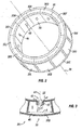
- FIG. 2 some aspects of a non-limiting example of an individual circumferential row or ringlet of resonators 21 are depicted in accordance with an embodiment of the present disclosure.
- a single ringlet 30 having a plurality of resonators 21 is illustrated.
- the ringlet 30 includes a plurality of resonator openings 40 that are exposed to the internal passage 22 for attenuating and absorbing sound via the resonators 21.
- each resonator 21 includes a single opening 40, although it will be understood that in other embodiments an individual resonator 21 may include more than one opening 40.
- a circumferential ringlet 30 may include twelve resonators 30A-30L (shown in dashed lines). It will be understood that a given ringlet 30 may include any number of resonators 21 depending upon, for example, the acoustic frequency or frequencies sought to be attenuated or absorbed by the particular resonator or resonators 21 of a particular ringlet 30.
- all of the resonators 21 in a particular circumferential row or ringlet 30 may be structured to attenuate and/or absorb the same frequency, whereas all of the resonators 21 in another circumferential row or ringlet, for example the resonators 24A-24L of row 24, may be structured to attenuating and absorb a different frequency. In some embodiments, the resonators 21 in a particular circumferential row or ringlet may be structured to attenuate and/or absorb one or more different frequencies.
- the annular ring 20 includes a plurality of circumferential rows or ringlets, each having a plurality resonators 21 similar in nature to resonator 30B.
- the resonator 30B, and each resonator 21, may include a neck 42 having a centerline 44, the neck 42 extending opposite the internal passage 22 from a surface adjacent the internal passage 22.
- the neck 42 further defines the opening or orifice 40 such that the neck 42 may extend from the perimeter of the orifice 40.
- the orifice 40 may be circular, polygonal, oblong (e.g., a slit) or any suitable shape. Accordingly, the orifice 40 may have an effective cross-sectional area or size A o .
- the neck 42 has an actual length L o .
- the resonator 30B includes a cavity 46 having a volume V and an area A c , where the area A c is defined as the cross-sectional area of the cavity 46 perpendicular to centerline 44.
- the cavity 46 is in communication with the internal passage 22 via the neck 42 and the orifice 40.
- the orifice size A o , the neck length L o , the volume V, the area A c , and/or one or more other physical parameters, pertaining to the size, shape, and/or orientation of the neck 42 or cavity 46, may vary as between resonators and/or as needed for the particular application.
- the orifice size A o and the length L o of the neck 42, and the volume V and the area A c of the cavity 46 may be selected to enable a desired response from each particular resonator 21.
- each resonator 21 may be selected to tune the resonator 21 to effectively dampening, attenuate, or absorb a desired acoustic wave frequency, to reduce or eliminate the amplitude of acoustic pressure waves at such desired frequency in the internal passage 22.
- each of resonators 24A-24L through 36A-36L may be tuned or configured to reduce the amplitude of an acoustic wave at a desired frequency F.
- a pressure wave incident upon the orifice 40 having a frequency at the natural frequency Fn of the resonator 30B will largely be reflected back to the source, creating an interference that attenuates and/or cancels the incident pressure wave.
- the attenuation of incident pressure waves may be quantified as a transmission loss produced by the resonator 30B.
- the plurality of resonators 21, including the resonator 30B, of the annular ring 20 may be tuned accordingly to the attenuate and/or cancel the acoustic pressure waves generated by the compressor 12.
- the resonators 21, like the resonator 30B, are Helmholtz resonators and function to attenuate and absorb acoustic pressure waves at one or more desired or predetermined frequencies.
- a Helmholtz resonator may be modeled as a simple oscillator in which the effective spring constant is determined by the compliance of the fluid in the cavity and its boundaries.
- the effective oscillator mass is the fluid (i.e., air) mass in the resonator neck 42 plus the entrained fluid (i.e., air) mass from within the cavity 46 and from the internal passage 22.
- the entrained air mass may be modeled as the reactive radiating loading on two virtual pistons forming the boundaries between the neck 42 and, respectively, the cavity 46 and the internal passage 22.
- the oscillation is generated by pressure waves, both aerodynamic and acoustic, incident upon the orifice 40 as the pressurized gas is discharged from the compressor 12 through the internal passage 22 of the silencer 18.
- the sloshing of the air through the orifice 40 as the air in the cavity 46 is alternately compressed and decompressed by incident pressure waves entrains a mass of air corresponding to orifice size A o , multiplied by the neck length L o , plus the entrained air outside the cavity. Because it is in motion, the entrained air mass moving through the orifice 40 has momentum that yields an effective neck length L e that is larger than the actual neck length, L o .
- the natural frequency of the resonator F n is dependent on the effective neck length L e , which depends on the overall dimensions of the resonator 30B, in addition to the actual neck length 42. Further, the natural frequency F n of the resonator 30B may be broadened due to varying angles of incidence of the pressure waves upon the orifice 40 caused by the shorter wavelengths of the aeroacoustic field and larger scale turbulence in flow of air through the internal passage 22.
- the annular ring 20 dampens, attenuates, and absorbs both aerodynamic and acoustic pressure waves.
- the compartmentalized structure of the annular ring 20 comprised of the plurality resonators 21 lends compliance to the walls of the silencer 18 enabling the annular ring 20 to attenuate and absorb pressure waves pulsations in the aerodynamic pressure field.
- the plurality of resonators 21 may be tuned to attenuate the various frequencies in the acoustic field generated by the compressor 12 as described herein.
- annular ring 20 of the silencer 18 may be disposed within the discharge pipe 16, the annular ruing 20 and the resonators 21 must be structured withstand the dynamic pressure of the aeroacoustic field, but not the full static pressure discharged by the compressor 12. By reducing or eliminating undesirable aerodynamic and acoustic pressure waves, noise may be reduced, and potential harm to compressor system 12 and/or downstream components may be abated or eliminated.
- the annular ring 20 and the discharge pipe 16 are disposed about a centerline 38 as shown in FIG. 1 , and in one form, are essentially cylindrical, or circular in cross-section. In other embodiments, the annular ring 20 and/or the discharge pipe 16 may have other shapes. In at least one embodiment, the annular ring 20 may be formed of a plurality of separate circumferential rows 24-36 that are assembled, stacked, and/or affixed to each other. Alternatively, the circumferential rows 24-36 of resonators 21 of the annular ring 20 may be formed as an integral, unitary structure.
- the silencer 18, the annular ring 20, and the circumferential rows 24-36 of resonators 21 may be formed as an integral, unitary structure that is separate from the discharge pipe 16 to form an acoustically absorptive liner, which can be inserted within and fitted to the discharge pipe 16 as shown in FIG. 4 .
- a compressor system 100 may include the compressor 12 having the discharge portion 14 connected to the discharge pipe 16.
- the compressor system 100 may further include the silencer 18, including the annular ring 20, inserted within and supported by the discharge pipe 16.
- the discharge pipe 16 may be exposed to significant stress due to the pressure difference between the relatively high pressure within the internal passage 22 and the relatively low ambient pressure surrounding the discharge pipe 16. Consequently, the discharge pipe 16 requires sufficient strength to withstand this pressure difference, which may be on the order of hundreds, or thousands, of pounds per square inch. Because the silencer 18 of the compressor system 100 is fitted within and supported by the discharge pipe 16, the silencer 18 does not need the structural strength to withstand the same pressure difference. Thus, the discharge pipe 16 provides structural integrity to the silencer 18, which is configured for sound attenuation.
- FIG. 5 illustrates the variation of the total pressure P T generated by the compressor 12 over a given period of time according to Equation 3.
- the dynamic pressure P d may vary as pressure waves move through the aeroacoustic field due to fluctuations from the aerodynamically unsteady flow as described herein.
- the static pressure generally remains relatively constant at a given operating condition of the compressor 12.
- the fluctuations in dynamic pressure P d are relatively small in magnitude compared to the static pressure P s , which is many magnitudes greater and on the order of hundreds, or thousands, of pounds per square inch. Consequently, the discharge pipe 16 may be structured to withstand the relatively high static pressure force, and the silencer 18 of the compressor system 100 may be structured to withstand the stresses imposed by the dynamic pressure only. The silencer 18 need not be structured to withstand the static or total pressures generated by the compressor 12.
- the silencer 18 may be manufactured separately from the compressor system 100 as an integral part and retrofit to a previously manufactured compressor system with a discharge pipe, in keeping with the description of FIG. 4 .
- the silencer 18 may be integral in that forms a part separate from the discharge pipe 16 in which it is installed.
- the cost of manufacturing the silencer 18 and the compressor system 100 may be reduced relative to conventional compressor systems having conventional noise dampening features.
- the silencer 18 may be inserted, slid, slipped, or otherwise installed into the discharge pipe 16.
- the silencer 18 can be secured in location within the discharge pipe 16 using any suitable mechanical, chemical, or metallurgical technique.
- the silencer 18 may be bonded within the discharge pipe 16 using an adhesive, such as an epoxy.
- the silencer 18 could be welded or brazed where compatible with materials being joined.
- the silencer 18 may be staked, crimped, or trapped within the discharge pipe 16.
- the silencer 18 is manufactured such that it is secured within the discharge pipe 16 by interference fit.
- the silencer 18 may be formed from multiple annular rings 20 assembled, stacked, and/or affixed together by any suitable means.
- One or more annular rings 20 assembled together may be considered a cartridge that can be inserted or installed into the discharge pipe 16. Further, the silencer 18 can be considered to be a cartridge that is slid into the discharge pipe 16. Moreover, more than one cartridge may be separately inserted into the discharge pipe 16 to form the silencer 18.
- the silencer 18 may be formed as an integral, unitary device having an outer wall separate from the discharge pipe 16.
- the silencer 18 may be formed such that each annular ring 20 may include the neck 42, orifice 40, the side walls defining the cavity 46 but excluding the outer wall.
- the discharge pipe 16 may provide the outer wall of each cavity 46 when the silencer 18 is inserted and secured in the discharge pipe 16.
- such an embodiment does not have a double wall composed of the discharge pipe wall and the silencer wall. Such an embodiment further reduces cost and complexity of manufacturing the silencer 18.
- the silencer 18 may be manufactured by any suitable process. However, given the intricate features of the annular ring 20, it may or may not be possible to manufacture the silencer 18 by conventional molding, casting, or machining methods. In at least one embodiment according to the present disclosure, the silencer 18 and/or the annular ring 20 may be manufactured using an additive manufacturing process. Additive manufacturing is the process of forming an article by the selective fusion, sintering, or polymerization of a material stock. Additive manufacturing includes the use of a discretized computer-aided design ("CAD") data model of a desired part to define layers that may be processed successively in sequence to form the final integrated part.
- CAD computer-aided design
- Additive manufacturing includes powder bed fusion (“PBF”) and powder spray fusion (“PSF”) manufacturing processes, including selective laser melting (“SLM”), direct metal laser sintering (“DMLS”), selective laser sintering (“SLS”), and electron beam melting (“EBM”).
- PBF and PSF processes share a basic set of process steps, including one or more thermal sources to induce melting and fusing between powder particles of a material stock, a means for controlling fusion of the powder particles within prescribed regions of each layer of the discretized CAD model, and a means of depositing the powder particles on the previously fused layers forming the part-in-process.
- the prescribed regions of each layer are defined by the cross-section of the part CAD model in a given layer.
- the resultant part may be solid, substantially fully dense, substantially void-free, and has substantially equivalent or superior thermal and mechanically properties of a part manufactured by conventional molding, casting, or machining methods.
- the resultant part may include a desired degree of porosity by appropriate control of the manufacturing process.
- the silencer 18 and/or the annular ring 20 may be formed by a suitable casting technique, such as investment casting.
- Embodiments of the present invention include a compressor system, comprising: a compressor configured to discharge pressurized air; a discharge pipe in fluid communication with the compressor, wherein the discharge pipe is configured to conduct the pressurized air toward a desired location; and an annular ring inserted in the discharge pipe, wherein the annular ring has an internal passage configured to conduct the pressurized air from the compressor therethrough, wherein the annular ring includes a resonator in fluid communication with the internal passage; and wherein the resonator is configured to reduce pressure fluctuations in the pressurized air discharged by the compressor.
- the annular ring is an integral, unitary structure and is separate from and supported by the discharge pipe.
- the annular ring includes a plurality of resonators circumferentially spaced apart about the annular ring.
- the resonator includes a cavity having a volume and an area; wherein the resonator includes a neck having a length and an orifice size; and wherein the cavity is in fluid communication with the internal passage via the neck.
- the resonator is tuned to attenuate a desired frequency by varying one or more of the volume, the area, the length and the orifice size.
- the annular ring includes a first circumferential row of resonators circumferentially spaced apart about the annular ring.
- each resonator in the first circumferential row of resonators is tuned to attenuate acoustic waves the same frequency.
- the annular ring includes a second circumferential row of resonators circumferentially spaced apart about the annular ring.
- the resonators of the first circumferential row of resonators are tuned to attenuate one or more different frequencies than the resonators of the second circumferential row of resonators.
- each resonator of the first circumferential row of resonators is tuned to attenuate a first frequency; and wherein each resonator of the second circumferential row of resonators is tuned to attenuate a second frequency different from the first frequency.
- the second circumferential row of resonators is positioned adjacent to the first circumferential row of resonators.
- the annular ring includes a third circumferential row of resonators circumferentially spaced apart about the annular ring.
- Embodiments of the present invention further include a compressor system, comprising: a screw compressor; a screw compressor discharge pipe having an outer surface and an internal passage disposed radially inward of the outer surface, wherein the internal passage configured to conduct pressurized air discharged from the screw compressor therethrough; and a plurality of resonators inserted between the outer surface and the internal passage, wherein each resonator includes an opening in fluid communication with the internal passage; and wherein each resonator is configured to attenuate acoustic pressure waves at a predetermined frequency.
- a compressor system comprising: a screw compressor; a screw compressor discharge pipe having an outer surface and an internal passage disposed radially inward of the outer surface, wherein the internal passage configured to conduct pressurized air discharged from the screw compressor therethrough; and a plurality of resonators inserted between the outer surface and the internal passage, wherein each resonator includes an opening in fluid communication with the internal passage; and wherein each resonator is configured to attenuate
- the plurality of resonators are arranged in a plurality of circumferential rows of resonators circumferentially spaced apart.
- At least one circumferential row of resonators is structured to attenuate acoustic pressure waves at a different frequency than at least one other circumferential row of resonators.
- the plurality of resonators are formed as part of an integral, unitary structure.
- the plurality of resonators are formed as part of an integral, unitary annular ring defined between the internal passage and the outer surface.
- the annular ring is formed by an additive manufacturing process.
- Embodiments of the present invention further include a compressor system, comprising: a compressor operative to discharge pressurized air having acoustic pressure waves therein; a discharge pipe in fluid communication with the compressor, wherein the discharge pipe is configured to conduct the pressurized air toward a desired location; and means for reducing amplitudes of the acoustic pressure waves at one or more preselected frequencies, wherein the means of reducing amplitudes is disposed within the discharge pipe.
- a compressor system comprising: a compressor operative to discharge pressurized air having acoustic pressure waves therein; a discharge pipe in fluid communication with the compressor, wherein the discharge pipe is configured to conduct the pressurized air toward a desired location; and means for reducing amplitudes of the acoustic pressure waves at one or more preselected frequencies, wherein the means of reducing amplitudes is disposed within the discharge pipe.
- the means for reducing is formed as an integral, unitary structure having a plurality of Helmholtz resonators.
Landscapes
- Engineering & Computer Science (AREA)
- General Engineering & Computer Science (AREA)
- Mechanical Engineering (AREA)
- Structures Of Non-Positive Displacement Pumps (AREA)
Description
- The present invention relates to compressor systems, and more particularly, to compressor systems with noise reduction.
- Systems that effectively reduce the amplitudes of pressure waves in the pressurized air discharged by a compressor remain an area of interest. Such pressure waves may include aerodynamic pressure and aeroacoustic pressure. Some existing systems have various shortcomings, drawbacks, and disadvantages relative to certain applications. Accordingly, there remains a need for further contributions in this area of technology.
- In one form, a compressor system includes a compressor, and an annular ring disposed downstream of the compressor and structured to reduce pressure fluctuations in the pressurized air discharged by the compressor. The annular ring may include an internal passage for conducting the pressurized air. The annular ring may include at least one resonator in fluid communication with the internal passage. Further embodiments, forms, features, aspects, benefits, and advantages of the present application will become apparent from the description and figures provided herewith.
- The description herein makes reference to the accompanying drawings wherein like reference numerals refer to like parts throughout the several views, and wherein:
-
FIG. 1 schematically illustrates some aspects of a non-limiting example of a resonator in accordance with an embodiment of the present invention. -
FIG. 2 is an isometric view illustrating some aspects of a non-limiting example of a circumferential row of resonators in accordance with an embodiment of the present invention. -
FIG. 3 is a sectional view illustrating some aspects of a non-limiting example of a resonator in accordance with an embodiment of the present invention. -
FIG. 4 is a sectional view illustrating some aspects of a non-limiting example of a resonator in accordance with an embodiment of the present invention. -
FIG. 5 is a graph illustrating total pressure over time for a non-limiting example of a resonator in accordance with an embodiment of the present invention. - For purposes of promoting an understanding of the principles of the invention, reference will now be made to the embodiments illustrated in the drawings, and specific language will be used to describe the same. It will nonetheless be understood that no limitation of the scope of the invention is intended by the illustration and description of certain embodiments of the invention. In addition, any alterations and/or modifications of the illustrated and/or described embodiment(s) are contemplated as being within the scope of the present invention. Further, any other applications of the principles of the invention, as illustrated and/or described herein, as would normally occur to one skilled in the art to which the invention pertains, are contemplated as being within the scope of the present invention.
- Referring to the drawings, and in particular
FIG. 1 , some aspects of a non-limiting example of acompressor system 10 are depicted in accordance with an embodiment of the present disclosure.Compressor system 10 includes acompressor 12 having adischarge portion 14, and adischarge pipe 16 in fluid communication with thecompressor 12 for conducting the pressurized air from thecompressor 12 toward a desired location, e.g., to or toward one or more downstream components (not shown) that employ pressurized air. In one form, thedischarge pipe 16 is integral with thecompressor 12, although in other embodiments, thedischarge pipe 16 may be a discrete component attached to or otherwise coupled or affixed to thecompressor 12, directly or indirectly. Thedischarge pipe 16 includes anouter surface 16A and aninternal pipe passage 16B. In one form, thecompressor 12 is a screw compressor. In a particular form, thecompressor 12 is an oil-free screw compressor. In other embodiments, thecompressor 12 may be a piston compressor, a lobed compressor, or any positive displacement compressor. In still other embodiments, thecompressor 12 may be a centrifugal compressor or another type of compressor. Thecompressor 12 is configured to discharge pressurized air via thedischarge portion 14 and through thedischarge pipe 16 to a desired location. - During normal operation,
compressor 12 pressurizes gas, such as ambient air, and discharges the pressurized gas for use by the downstream components. In some operating conditions, thecompressor 12 may produce pressure pulsations, which may be a significant or primary source of noise generated from thecompressor 12. The generation of sound may be either from structural vibration or from aerodynamically unsteady flow. The latter, referred to as aeroacoustic, is the result of unsteady flow fields that radiate sound into the far field. The aeroacoustic field includes two kinds of pressure: pressure due to the aerodynamic forces and pressure due to the acoustic field that radiates from the existence of the aerodynamic flow. Aerodynamic pressure is created by a pressure field that is the result of the transfer of mass, such as the pressurized gas discharged from thecompressor 12. Acoustic pressure is created as the acoustic field transfers vibration as a longitudinal wave without the transfer of mass. Though generally the dominant pressure field is the aerodynamic pressure, both pressure fields exist and contribute to the resulting dynamic pressure and, thereby, the sound generated by thecompressor 12. - Untreated, the amplitudes of the pulsations from the
compressor 12 may cause harm to downstream piping and other components, and/or may cause undesirable noise levels. For example, a typical oil-free screw compressor rated for 100 pounds per square inch gauge (psig) may have a dynamic pressure at the compressor discharge with a peak-to-peak amplitude that ranges between about 80 psig and about 120 psig. For a screw compressor, the fundamental frequency of oscillation is a port passing frequency at the discharge of the compressor. The port passing frequency represents the number of times the compressor discharge port is opened to allow compressed air to escape into thedischarge pipe 16. It is desirable to reduce the pressure pulsations to amplitudes that are acceptable for both system reliability and noise constraints. Accordingly, embodiments of the present invention include asilencer 18 disposed within thedischarge pipe 16. In some embodiments, thesilencer 18 may be formed integrally with thedischarge pipe 16, whereas in other embodiments,silencer 18 may be fitted within thedischarge pipe 16 to form an acoustically absorptive liner within thedischarge pipe 16. - In at least one embodiment of the present disclosure, the
silencer 18 includes anannular ring 20 disposed within thedischarge pipe 16. Theannular ring 20 includes aninternal passage 22 structured to enable the pressurized air from thecompressor 12 to flow therethrough to downstream components via thedischarge pipe 16. In some embodiments, theinternal passage 22 defines all or a portion of theinternal pipe passage 16B. Theannular ring 20 may include a plurality ofresonators 21 in fluid communication with theinternal passage 22. Eachresonator 21 in theannular ring 20 is structured to reduce pressure fluctuations in the pressurized air discharged bycompressor 12 and effectively dampen, attenuate, or absorb acoustic pressure waves at one or more desired frequencies, in whole or in part. - In one form, the
annular ring 20 includes a plurality of circumferential rows 24-36 ofresonators 21, wherein each circumferential row ofresonators 21 includes a plurality ofresonators 21 that are circumferentially spaced apart, i.e., spaced apart about or around the circumference of a particular circumferential row of theannular ring 20. In one form, each circumferential row ofresonators 21 is adjacent to the next, though it will be understood that theannular ring 20 is not limited to a particular scheme of spacing the circumferential rows 24-36 ofresonators 21 relative to each other. In the depiction ofFIG. 1 , because theannular ring 20 is illustrated in cross-section, only tworesonators 21 for each circumferential row 24-36 are illustrated, i.e.,resonators resonators 21, and the illustrated embodiment includes more than tworesonators 21 per row. In the illustrated embodiment, theannular ring 20 includes twelveresonators 21 per row, specifically,resonators 24A-24L forcircumferential row 24, although only two,resonators FIG. 1 . Further, though seven rows (24, 26, 28, 30, 34 and 36) are depicted, it will be understood that theannular ring 20 may include any number of circumferential rows having any number ofresonators 21 per circumferential row. Moreover, in many applications each circumferential row may include a different number ofresonators 21 than one or more other circumferential rows. In such an embodiment, theresonators 21 may be of different sizes within a given row and thus have different pressure absorption or canceling capacity from row to row as described further herein. ThoughFIG. 1 illustratesresonators 21 having the same size, it will be understood thatFIG. 1 is merely illustrative in nature, and that the number and the size of theresonators 21 may vary from location to location within theannular ring 20. - For purposes of description, each circumferential row of
resonators 21 may be referred to as a ringlet, such that a plurality of rows or ringlets, e.g., rows/ringlets 24-36, form theannular ring 20. Referring toFIG. 2 , some aspects of a non-limiting example of an individual circumferential row or ringlet ofresonators 21 are depicted in accordance with an embodiment of the present disclosure. InFIG. 2 , asingle ringlet 30 having a plurality ofresonators 21 is illustrated. Theringlet 30 includes a plurality ofresonator openings 40 that are exposed to theinternal passage 22 for attenuating and absorbing sound via theresonators 21. In one form, eachresonator 21 includes asingle opening 40, although it will be understood that in other embodiments anindividual resonator 21 may include more than oneopening 40. As shown inFIG. 2 , acircumferential ringlet 30 may include twelveresonators 30A-30L (shown in dashed lines). It will be understood that a givenringlet 30 may include any number ofresonators 21 depending upon, for example, the acoustic frequency or frequencies sought to be attenuated or absorbed by the particular resonator orresonators 21 of aparticular ringlet 30. In some embodiments, all of theresonators 21 in a particular circumferential row orringlet 30 may be structured to attenuate and/or absorb the same frequency, whereas all of theresonators 21 in another circumferential row or ringlet, for example theresonators 24A-24L ofrow 24, may be structured to attenuating and absorb a different frequency. In some embodiments, theresonators 21 in a particular circumferential row or ringlet may be structured to attenuate and/or absorb one or more different frequencies. - Referring to
FIG. 3 , some aspects of a non-limiting example of theresonator 30B are depicted in accordance with an embodiment of the present disclosure. As set forth above, in the depicted embodiment, theannular ring 20 includes a plurality of circumferential rows or ringlets, each having aplurality resonators 21 similar in nature toresonator 30B. Theresonator 30B, and eachresonator 21, may include aneck 42 having acenterline 44, theneck 42 extending opposite theinternal passage 22 from a surface adjacent theinternal passage 22. Theneck 42 further defines the opening ororifice 40 such that theneck 42 may extend from the perimeter of theorifice 40. Theorifice 40 may be circular, polygonal, oblong (e.g., a slit) or any suitable shape. Accordingly, theorifice 40 may have an effective cross-sectional area or size Ao. Theneck 42 has an actual length Lo. Theresonator 30B includes acavity 46 having a volume V and an area Ac, where the area Ac is defined as the cross-sectional area of thecavity 46 perpendicular tocenterline 44. Thecavity 46 is in communication with theinternal passage 22 via theneck 42 and theorifice 40. The orifice size Ao, the neck length Lo, the volume V, the area Ac, and/or one or more other physical parameters, pertaining to the size, shape, and/or orientation of theneck 42 orcavity 46, may vary as between resonators and/or as needed for the particular application. In one form, the orifice size Ao and the length Lo of theneck 42, and the volume V and the area Ac of thecavity 46, may be selected to enable a desired response from eachparticular resonator 21. For example, the physical parameters of eachresonator 21 may be selected to tune theresonator 21 to effectively dampening, attenuate, or absorb a desired acoustic wave frequency, to reduce or eliminate the amplitude of acoustic pressure waves at such desired frequency in theinternal passage 22. - In one form, each of
resonators 24A-24L through 36A-36L may be tuned or configured to reduce the amplitude of an acoustic wave at a desired frequency F. In one form, theresonator 30B may be tuned or configured by selecting or varying the values of the orifice size Ao and/or the length Lo of theneck 42, and/or the volume V and/or the area Ac for thecavity 46, to produce a resonator natural frequency Fn, as calculated by:

wherein c is the speed of sound at the local air density; Ao is the effective orifice size (i.e., cross-sectional area) of theneck 42; Lo is the actual length of theneck 42; V is the volume of thecavity 46; Ac is the cross-sectional area ofcavity 46; Le is the effective neck length as described herein; and Fn is the natural frequency of theresonator 30B. - A pressure wave incident upon the
orifice 40 having a frequency at the natural frequency Fn of theresonator 30B will largely be reflected back to the source, creating an interference that attenuates and/or cancels the incident pressure wave. The attenuation of incident pressure waves may be quantified as a transmission loss produced by theresonator 30B. The plurality ofresonators 21, including theresonator 30B, of theannular ring 20 may be tuned accordingly to the attenuate and/or cancel the acoustic pressure waves generated by thecompressor 12. - In one form, the
resonators 21, like theresonator 30B, are Helmholtz resonators and function to attenuate and absorb acoustic pressure waves at one or more desired or predetermined frequencies. A Helmholtz resonator may be modeled as a simple oscillator in which the effective spring constant is determined by the compliance of the fluid in the cavity and its boundaries. In this framework, the effective oscillator mass is the fluid (i.e., air) mass in theresonator neck 42 plus the entrained fluid (i.e., air) mass from within thecavity 46 and from theinternal passage 22. The entrained air mass may be modeled as the reactive radiating loading on two virtual pistons forming the boundaries between theneck 42 and, respectively, thecavity 46 and theinternal passage 22. - The oscillation is generated by pressure waves, both aerodynamic and acoustic, incident upon the
orifice 40 as the pressurized gas is discharged from thecompressor 12 through theinternal passage 22 of thesilencer 18. The sloshing of the air through theorifice 40 as the air in thecavity 46 is alternately compressed and decompressed by incident pressure waves entrains a mass of air corresponding to orifice size Ao, multiplied by the neck length Lo, plus the entrained air outside the cavity. Because it is in motion, the entrained air mass moving through theorifice 40 has momentum that yields an effective neck length Le that is larger than the actual neck length, Lo. Consequently, the natural frequency of the resonator Fn is dependent on the effective neck length Le, which depends on the overall dimensions of theresonator 30B, in addition to theactual neck length 42. Further, the natural frequency Fn of theresonator 30B may be broadened due to varying angles of incidence of the pressure waves upon theorifice 40 caused by the shorter wavelengths of the aeroacoustic field and larger scale turbulence in flow of air through theinternal passage 22. - Accordingly, the
annular ring 20 dampens, attenuates, and absorbs both aerodynamic and acoustic pressure waves. In one aspect as shown inFIG. 1 , the compartmentalized structure of theannular ring 20 comprised of theplurality resonators 21 lends compliance to the walls of thesilencer 18 enabling theannular ring 20 to attenuate and absorb pressure waves pulsations in the aerodynamic pressure field. In another aspect of theannular ring 20, the plurality ofresonators 21 may be tuned to attenuate the various frequencies in the acoustic field generated by thecompressor 12 as described herein. Further, because theannular ring 20 of thesilencer 18 may be disposed within thedischarge pipe 16, theannular ruing 20 and theresonators 21 must be structured withstand the dynamic pressure of the aeroacoustic field, but not the full static pressure discharged by thecompressor 12. By reducing or eliminating undesirable aerodynamic and acoustic pressure waves, noise may be reduced, and potential harm tocompressor system 12 and/or downstream components may be abated or eliminated. - In one form, the
annular ring 20 and thedischarge pipe 16 are disposed about acenterline 38 as shown inFIG. 1 , and in one form, are essentially cylindrical, or circular in cross-section. In other embodiments, theannular ring 20 and/or thedischarge pipe 16 may have other shapes. In at least one embodiment, theannular ring 20 may be formed of a plurality of separate circumferential rows 24-36 that are assembled, stacked, and/or affixed to each other. Alternatively, the circumferential rows 24-36 ofresonators 21 of theannular ring 20 may be formed as an integral, unitary structure. - In at least one embodiment according to the present disclosure, the
silencer 18, theannular ring 20, and the circumferential rows 24-36 ofresonators 21 may be formed as an integral, unitary structure that is separate from thedischarge pipe 16 to form an acoustically absorptive liner, which can be inserted within and fitted to thedischarge pipe 16 as shown inFIG. 4 . In such an embodiment, acompressor system 100 may include thecompressor 12 having thedischarge portion 14 connected to thedischarge pipe 16. Thecompressor system 100 may further include thesilencer 18, including theannular ring 20, inserted within and supported by thedischarge pipe 16. Depending on the compressed gas pressure generated by thecompressor 12, thedischarge pipe 16 may be exposed to significant stress due to the pressure difference between the relatively high pressure within theinternal passage 22 and the relatively low ambient pressure surrounding thedischarge pipe 16. Consequently, thedischarge pipe 16 requires sufficient strength to withstand this pressure difference, which may be on the order of hundreds, or thousands, of pounds per square inch. Because thesilencer 18 of thecompressor system 100 is fitted within and supported by thedischarge pipe 16, thesilencer 18 does not need the structural strength to withstand the same pressure difference. Thus, thedischarge pipe 16 provides structural integrity to thesilencer 18, which is configured for sound attenuation. - The total pressure generated by the
compressor 12 includes both a dynamic pressure resulting from the aerodynamically unsteady flow emanating from thedischarge portion 14 and a static pressure resulting from the compression process as shown in Equation 3:
where PT is the total pressure, Pd is the dynamic pressure, and Ps is the static pressure.FIG. 5 illustrates the variation of the total pressure PT generated by thecompressor 12 over a given period of time according toEquation 3. As depicted inFIG. 5 , the dynamic pressure Pd may vary as pressure waves move through the aeroacoustic field due to fluctuations from the aerodynamically unsteady flow as described herein. However, the static pressure generally remains relatively constant at a given operating condition of thecompressor 12. Further, the fluctuations in dynamic pressure Pd are relatively small in magnitude compared to the static pressure Ps, which is many magnitudes greater and on the order of hundreds, or thousands, of pounds per square inch. Consequently, thedischarge pipe 16 may be structured to withstand the relatively high static pressure force, and thesilencer 18 of thecompressor system 100 may be structured to withstand the stresses imposed by the dynamic pressure only. Thesilencer 18 need not be structured to withstand the static or total pressures generated by thecompressor 12. Thus, thesilencer 18 may be manufactured separately from thecompressor system 100 as an integral part and retrofit to a previously manufactured compressor system with a discharge pipe, in keeping with the description ofFIG. 4 . Thesilencer 18 may be integral in that forms a part separate from thedischarge pipe 16 in which it is installed. Moreover, the cost of manufacturing thesilencer 18 and thecompressor system 100 may be reduced relative to conventional compressor systems having conventional noise dampening features. - In such an embodiment, the
silencer 18 may be inserted, slid, slipped, or otherwise installed into thedischarge pipe 16. Thesilencer 18 can be secured in location within thedischarge pipe 16 using any suitable mechanical, chemical, or metallurgical technique. By way of non-limiting example, thesilencer 18 may be bonded within thedischarge pipe 16 using an adhesive, such as an epoxy. Alternatively, thesilencer 18 could be welded or brazed where compatible with materials being joined. In further examples, thesilencer 18 may be staked, crimped, or trapped within thedischarge pipe 16. In at least one embodiment, thesilencer 18 is manufactured such that it is secured within thedischarge pipe 16 by interference fit. - The
silencer 18 may be formed from multipleannular rings 20 assembled, stacked, and/or affixed together by any suitable means. One or moreannular rings 20 assembled together may be considered a cartridge that can be inserted or installed into thedischarge pipe 16. Further, thesilencer 18 can be considered to be a cartridge that is slid into thedischarge pipe 16. Moreover, more than one cartridge may be separately inserted into thedischarge pipe 16 to form thesilencer 18. - In at least one embodiment, as shown in
FIG. 4 , thesilencer 18 may be formed as an integral, unitary device having an outer wall separate from thedischarge pipe 16. Alternatively, thesilencer 18 may be formed such that eachannular ring 20 may include theneck 42,orifice 40, the side walls defining thecavity 46 but excluding the outer wall. In such an embodiment, thedischarge pipe 16 may provide the outer wall of eachcavity 46 when thesilencer 18 is inserted and secured in thedischarge pipe 16. Unlike the depiction inFIG. 4 , such an embodiment does not have a double wall composed of the discharge pipe wall and the silencer wall. Such an embodiment further reduces cost and complexity of manufacturing thesilencer 18. - The
silencer 18 may be manufactured by any suitable process. However, given the intricate features of theannular ring 20, it may or may not be possible to manufacture thesilencer 18 by conventional molding, casting, or machining methods. In at least one embodiment according to the present disclosure, thesilencer 18 and/or theannular ring 20 may be manufactured using an additive manufacturing process. Additive manufacturing is the process of forming an article by the selective fusion, sintering, or polymerization of a material stock. Additive manufacturing includes the use of a discretized computer-aided design ("CAD") data model of a desired part to define layers that may be processed successively in sequence to form the final integrated part. Additive manufacturing includes powder bed fusion ("PBF") and powder spray fusion ("PSF") manufacturing processes, including selective laser melting ("SLM"), direct metal laser sintering ("DMLS"), selective laser sintering ("SLS"), and electron beam melting ("EBM"). PBF and PSF processes share a basic set of process steps, including one or more thermal sources to induce melting and fusing between powder particles of a material stock, a means for controlling fusion of the powder particles within prescribed regions of each layer of the discretized CAD model, and a means of depositing the powder particles on the previously fused layers forming the part-in-process. The prescribed regions of each layer are defined by the cross-section of the part CAD model in a given layer. Because the powder particles are melted and fused to the previous layer, the resultant part may be solid, substantially fully dense, substantially void-free, and has substantially equivalent or superior thermal and mechanically properties of a part manufactured by conventional molding, casting, or machining methods. Alternatively, the resultant part may include a desired degree of porosity by appropriate control of the manufacturing process. Alternatively, thesilencer 18 and/or theannular ring 20 may be formed by a suitable casting technique, such as investment casting. - Embodiments of the present invention include a compressor system, comprising: a compressor configured to discharge pressurized air; a discharge pipe in fluid communication with the compressor, wherein the discharge pipe is configured to conduct the pressurized air toward a desired location; and an annular ring inserted in the discharge pipe, wherein the annular ring has an internal passage configured to conduct the pressurized air from the compressor therethrough, wherein the annular ring includes a resonator in fluid communication with the internal passage; and wherein the resonator is configured to reduce pressure fluctuations in the pressurized air discharged by the compressor.
- In a refinement, the annular ring is an integral, unitary structure and is separate from and supported by the discharge pipe.
- In another refinement, the annular ring includes a plurality of resonators circumferentially spaced apart about the annular ring.
- In yet another refinement, the resonator includes a cavity having a volume and an area; wherein the resonator includes a neck having a length and an orifice size; and wherein the cavity is in fluid communication with the internal passage via the neck.
- In still another refinement, the resonator is tuned to attenuate a desired frequency by varying one or more of the volume, the area, the length and the orifice size.
- In yet still another refinement, the annular ring includes a first circumferential row of resonators circumferentially spaced apart about the annular ring.
- In a further refinement, each resonator in the first circumferential row of resonators is tuned to attenuate acoustic waves the same frequency.
- In a yet further refinement, the annular ring includes a second circumferential row of resonators circumferentially spaced apart about the annular ring.
- In a still further refinement, the resonators of the first circumferential row of resonators are tuned to attenuate one or more different frequencies than the resonators of the second circumferential row of resonators.
- In a yet still further refinement, each resonator of the first circumferential row of resonators is tuned to attenuate a first frequency; and wherein each resonator of the second circumferential row of resonators is tuned to attenuate a second frequency different from the first frequency.
- In another refinement, the second circumferential row of resonators is positioned adjacent to the first circumferential row of resonators.
- In still another refinement, the annular ring includes a third circumferential row of resonators circumferentially spaced apart about the annular ring.
- Embodiments of the present invention further include a compressor system, comprising: a screw compressor; a screw compressor discharge pipe having an outer surface and an internal passage disposed radially inward of the outer surface, wherein the internal passage configured to conduct pressurized air discharged from the screw compressor therethrough; and a plurality of resonators inserted between the outer surface and the internal passage, wherein each resonator includes an opening in fluid communication with the internal passage; and wherein each resonator is configured to attenuate acoustic pressure waves at a predetermined frequency.
- In another refinement, the plurality of resonators are arranged in a plurality of circumferential rows of resonators circumferentially spaced apart.
- In yet another refinement, at least one circumferential row of resonators is structured to attenuate acoustic pressure waves at a different frequency than at least one other circumferential row of resonators.
- In still another refinement, the plurality of resonators are formed as part of an integral, unitary structure.
- In yet still another refinement, the plurality of resonators are formed as part of an integral, unitary annular ring defined between the internal passage and the outer surface.
- In another refinement, the annular ring is formed by an additive manufacturing process.
- Embodiments of the present invention further include a compressor system, comprising: a compressor operative to discharge pressurized air having acoustic pressure waves therein; a discharge pipe in fluid communication with the compressor, wherein the discharge pipe is configured to conduct the pressurized air toward a desired location; and means for reducing amplitudes of the acoustic pressure waves at one or more preselected frequencies, wherein the means of reducing amplitudes is disposed within the discharge pipe.
- In a refinement, the means for reducing is formed as an integral, unitary structure having a plurality of Helmholtz resonators.
- While the invention has been described in connection with particular embodiments, it is to be understood that the invention is not to be limited to the disclosed embodiment but, on the contrary, is intended to cover various modifications and equivalent arrangements included within the spirit and scope of the appended claims, which scope is to be accorded the broadest interpretation so as to encompass all such modifications and equivalent structures as permitted under the law. Furthermore it should be understood that while the use of the word preferable, preferably, or preferred in the description above indicates that feature so described may be more desirable, it nonetheless may not be necessary and any embodiment lacking the same may be contemplated as within the scope of the invention, that scope being defined by the claims that follow. In reading the claims it is intended that when words such as "a," "an," "at least one" and "at least a portion" are used, there is no intention to limit the claim to only one item unless specifically stated to the contrary in the claim. Further, when the language "at least a portion" and/or "a portion" is used the item may include a portion and/or the entire item unless specifically stated to the contrary.
Claims (15)
- A compressor system, comprising:a compressor structured to discharge a flow of pressurized gas;a discharge pipe in fluid communication with the compressor, wherein the discharge pipe is structured to conduct the pressurized gas toward a desired location; andan annular ring inserted into the discharge pipe, wherein the annular ring has an internal passage structured to conduct the pressurized gas from the compressor therethrough,wherein the annular ring includes a resonator in fluid communication with the internal passage, andwherein the resonator is configured to reduce pressure fluctuations in the flow of pressurized gas discharged by the compressor.
- The compressor system of claim 1, wherein the annular ring is an integral structure and is separate from and supported by the discharge pipe; or
wherein the annular ring includes a plurality of resonators circumferentially spaced apart about the annular ring. - The compressor system of claim 1, wherein the resonator includes a cavity, having a volume and an area, and a neck having a length and an orifice size, and wherein the cavity is in fluid communication with the internal passage via the neck.
- The compressor system of claim 3, wherein the resonator is tuned to attenuate a desired frequency by varying one or more of the volume, the area, the length and the orifice size.
- The compressor system of claim 1, wherein the annular ring includes a first circumferential row of resonators circumferentially spaced apart about the annular ring.
- The compressor system of claim 5, wherein each resonator in the first circumferential row of resonators is tuned to attenuate acoustic waves of the same frequency; or
- The compressor system of claim 6, wherein the annular ring includes a second circumferential row of resonators circumferentially spaced apart about the annular ring.
- The compressor system of claim 7, wherein the resonators of the first circumferential row of resonators are tuned to attenuate one or more different frequencies than the resonators of the second circumferential row of resonators.
- The compressor system of claim 8, wherein each resonator of the first circumferential row of resonators is tuned to attenuate a first frequency, and wherein each resonator of the second circumferential row of resonators is tuned to attenuate a second frequency different from the first frequency; or
wherein the second circumferential row of resonators is positioned adjacent to the first circumferential row of resonators; or
wherein the annular ring includes a third circumferential row of resonators circumferentially spaced apart about the annular ring. - A compressor system, comprising:a screw compressor;a screw compressor discharge pipe having an outer surface and an internal passage disposed radially within the outer surface, wherein the internal passage is structured to conduct pressurized air discharged from the screw compressor therethrough; anda plurality of resonators inserted between the outer surface and the internal passage, wherein each resonator includes an opening in fluid communication with the internal passage, and wherein each resonator is structured to attenuate acoustic pressure waves at a predetermined frequency.
- The compressor system of claim 10, wherein the plurality of resonators are arranged in a plurality of circumferential rows of resonators circumferentially spaced apart.
- The compressor system of claim 11, wherein at least one circumferential row of resonators is structured to attenuate acoustic pressure waves at a different frequency than at least one other circumferential row of resonators; or
wherein the plurality of resonators are formed as part of an integral structure and are separate from and supported by the discharge pipe. - The compressor system of claim 10, wherein the plurality of resonators are formed as part of an integral annular ring defined between the internal passage and the outer surface.
- A compressor system, comprising:a compressor operative to discharge pressurized air having acoustic pressure waves therein;a discharge pipe in fluid communication with the compressor, wherein the discharge pipe is configured to conduct the pressurized air toward a desired location; and means for reducing amplitudes of the acoustic pressure waves at one or more preselected frequencies, wherein the means of reducing amplitudes is disposed within the discharge pipe.
- The compressor system of claim 14, wherein the means for reducing is formed as an integral, unitary structure having a plurality of Helmholtz resonators.
Applications Claiming Priority (1)
| Application Number | Priority Date | Filing Date | Title |
|---|---|---|---|
| US14/293,886 US9546660B2 (en) | 2014-06-02 | 2014-06-02 | Compressor system with resonator |
Publications (2)
| Publication Number | Publication Date |
|---|---|
| EP2952747A1 true EP2952747A1 (en) | 2015-12-09 |
| EP2952747B1 EP2952747B1 (en) | 2018-03-21 |
Family
ID=53773167
Family Applications (1)
| Application Number | Title | Priority Date | Filing Date |
|---|---|---|---|
| EP15170228.9A Active EP2952747B1 (en) | 2014-06-02 | 2015-06-02 | Compressor system with resonator |
Country Status (4)
| Country | Link |
|---|---|
| US (1) | US9546660B2 (en) |
| EP (1) | EP2952747B1 (en) |
| CN (1) | CN105134557B (en) |
| ES (1) | ES2673857T3 (en) |
Cited By (4)
| Publication number | Priority date | Publication date | Assignee | Title |
|---|---|---|---|---|
| EP3204936A4 (en) * | 2014-10-08 | 2018-08-29 | Dresser Rand Company | Concentric resonators for machines |
| EP3473910A1 (en) * | 2017-10-23 | 2019-04-24 | Hamilton Sundstrand Corporation | Duct assembly having internal noise reduction features, thermal insulation and leak detection |
| EP3995237A1 (en) * | 2020-11-05 | 2022-05-11 | Siemens Energy Global GmbH & Co. KG | Radiation strategy for the additive manufacture of a component and corresponding component |
| WO2023194120A1 (en) * | 2022-04-09 | 2023-10-12 | Hydac Technology Gmbh | Damping device |
Families Citing this family (36)
| Publication number | Priority date | Publication date | Assignee | Title |
|---|---|---|---|---|
| US10731648B2 (en) * | 2014-11-07 | 2020-08-04 | Trane International Inc. | Sound control for a heating, ventilation, and air conditioning unit |
| CN105386978B (en) * | 2015-11-30 | 2017-11-07 | 珠海格力电器股份有限公司 | Exhaust bearing seat connecting structure for compressor and screw compressor |
| CN106205584A (en) * | 2016-07-06 | 2016-12-07 | 南京大学 | A kind of broadband noise elimination pipeline of Helmholtz resonator based on adjustable resonant frequency |
| CN106205591A (en) * | 2016-07-18 | 2016-12-07 | 南京大学 | Miniature Helmholtz resonator broadband noise elimination pipeline based on space folding structure |
| CN108071601A (en) * | 2016-11-17 | 2018-05-25 | 英业达科技有限公司 | Centrifugal fan module |
| JP2018128153A (en) * | 2017-02-06 | 2018-08-16 | 三菱重工サーマルシステムズ株式会社 | refrigerator |
| CN107100820B (en) * | 2017-03-23 | 2019-08-16 | 青岛万宝压缩机有限公司 | Compressor for refrigeration air suction silencer |
| JP6902105B2 (en) * | 2017-10-03 | 2021-07-14 | 富士フイルム株式会社 | Silent tubular structure |
| WO2019074917A1 (en) | 2017-10-11 | 2019-04-18 | Carrier Corporation | Muffler with metallic meshed rings |
| CN107830590B (en) * | 2017-10-20 | 2023-07-21 | 珠海凌达压缩机有限公司 | Pipeline muffler and air conditioning system |
| EP3502475B1 (en) * | 2017-12-19 | 2022-02-23 | Nuovo Pignone Tecnologie SrL | A reciprocating compressor and manufacturing method |
| US10830102B2 (en) | 2018-03-01 | 2020-11-10 | General Electric Company | Casing with tunable lattice structure |
| JP7074878B2 (en) * | 2018-10-19 | 2022-05-24 | 富士フイルム株式会社 | Soundproof structure |
| CN111120332A (en) * | 2018-10-30 | 2020-05-08 | 安徽美芝制冷设备有限公司 | Silencer and rotary compressor with same |
| CN109990158B (en) * | 2019-04-19 | 2021-04-13 | 余红超 | A polypropylene anti-corrosion pipe joint |
| US11929053B2 (en) * | 2019-09-11 | 2024-03-12 | The Hong Kong University Of Science And Technology | Broadband sound absorber based on inhomogeneous-distributed Helmholtz resonators with extended necks |
| US11266921B1 (en) | 2020-08-19 | 2022-03-08 | Msg Entertainment Group, Llc | Atmospheric effects systems for presenting atmospheric effects relating to an event |
| CN112066143B (en) * | 2020-09-08 | 2022-02-08 | 河北骞海鼓风机有限公司 | Convenient-to-use soft air pipe for ventilator |
| KR102457169B1 (en) * | 2020-10-06 | 2022-10-20 | 재단법인 파동에너지 극한제어 연구단 | Silencer based on metamaterial structure |
| KR102463931B1 (en) * | 2020-10-28 | 2022-11-07 | 재단법인 파동에너지 극한제어 연구단 | Metamaterial muffler for noise reduction in wide bandfrequencies |
| KR102487101B1 (en) * | 2020-10-28 | 2023-01-10 | 재단법인 파동에너지 극한제어 연구단 | Metamaterial muffler for noise reduction in low frequency |
| US11986849B2 (en) * | 2021-01-15 | 2024-05-21 | Msg Entertainment Group, Llc | Air amplifier with noise suppression |
| KR102583152B1 (en) * | 2021-03-11 | 2023-10-04 | 재단법인 파동에너지 극한제어 연구단 | Acoustic metamaterial structure |
| CN215638255U (en) * | 2021-04-30 | 2022-01-25 | 青岛海尔特种制冷电器有限公司 | Air duct assembly and refrigeration appliance with the air duct assembly |
| CN113417829B (en) * | 2021-07-09 | 2022-05-27 | 同济大学 | Design method of multi-cavity muffler for fuel cell vehicle |
| CN114165481A (en) * | 2021-09-13 | 2022-03-11 | 荣耀终端有限公司 | Fan device and electronic equipment |
| CN114154233B (en) * | 2021-11-03 | 2025-03-14 | 东风汽车集团股份有限公司 | Intake resonator design method, device, equipment and readable storage medium |
| CN115376479A (en) * | 2022-04-07 | 2022-11-22 | 同济大学 | Sound absorption and bearing integrated structure based on perforated hollow rod and preparation method thereof |
| WO2024005993A1 (en) * | 2022-06-27 | 2024-01-04 | Danfoss A/S | Mufflers for refrigerant compressors |
| KR102731999B1 (en) * | 2022-10-31 | 2024-11-20 | 아주대학교산학협력단 | Acoustic metamaterial-based muffler for broadband exhaust noise reduction of internal combustion engines |
| DE102022211997A1 (en) | 2022-11-11 | 2024-05-16 | Siemens Aktiengesellschaft | Soundproofing component, its manufacture and use |
| CN116085789A (en) * | 2023-03-10 | 2023-05-09 | 江苏方天电力技术有限公司 | A noise-driven device for preventing accidental slag discharge pipe blockage in circulating fluidized bed boilers |
| US12623160B2 (en) | 2023-03-15 | 2026-05-12 | Sphere Entertainment Group, Llc | Closed loop feedback atmospheric effects systems |
| US12345278B2 (en) * | 2023-06-02 | 2025-07-01 | The Toro Company | Debris blower with sound attenuation resonator |
| US20250257675A1 (en) * | 2024-02-08 | 2025-08-14 | Ajou University Industry-Academic Cooperation Foundation | Acoustic metamaterial-based muffler for broadband exhaust noise reduction of internal combustion engines |
| CN119572493B (en) * | 2024-12-11 | 2025-10-31 | 百事德机械(江苏)有限公司 | Silencer for Roots blower |
Citations (4)
| Publication number | Priority date | Publication date | Assignee | Title |
|---|---|---|---|---|
| EP1291570A2 (en) * | 2001-09-07 | 2003-03-12 | Avon Polymer Products Limited | Noise and vibration suppressors |
| DE102011002869A1 (en) * | 2011-01-19 | 2012-07-19 | Siemens Aktiengesellschaft | reflection silencer |
| EP2495426A1 (en) * | 2011-03-01 | 2012-09-05 | Mann + Hummel GmbH | Swirl guiding acoustic device with an internal coaxially integrated swirl guide structure |
| WO2014051937A1 (en) * | 2012-09-27 | 2014-04-03 | Eaton Corporation | Integral resonators for roots-type supercharger |
Family Cites Families (17)
| Publication number | Priority date | Publication date | Assignee | Title |
|---|---|---|---|---|
| US4944362A (en) | 1988-11-25 | 1990-07-31 | General Electric Company | Closed cavity noise suppressor |
| US4927342A (en) | 1988-12-12 | 1990-05-22 | General Electric Company | Compressor noise attenuation using branch type resonator |
| US5957664A (en) | 1996-11-08 | 1999-09-28 | Air Products And Chemicals, Inc. | Gas pulsation dampener for positive displacement blowers and compressors |
| JPH11315784A (en) * | 1998-04-30 | 1999-11-16 | Tochigi Fuji Ind Co Ltd | Fluid machinery |
| US7055484B2 (en) | 2002-01-18 | 2006-06-06 | Carrier Corporation | Multiple frequency Helmholtz resonator |
| US6684842B1 (en) | 2002-07-12 | 2004-02-03 | Visteon Global Technologies, Inc. | Multi-chamber resonator |
| US20060065478A1 (en) | 2004-09-30 | 2006-03-30 | Rockwell David M | Compressor sound suppression |
| BRPI0419079A (en) * | 2004-10-20 | 2007-12-18 | Carrier Corp | compressor, silencer element, method for remanufacturing compressor or redesigning compressor configuration, compressor silencer element, compressor silencer |
| US7584821B2 (en) * | 2007-01-23 | 2009-09-08 | Gm Global Technology Operations, Inc. | Adjustable helmholtz resonator |
| DE102007004766A1 (en) * | 2007-01-31 | 2008-08-07 | Bayerische Motoren Werke Aktiengesellschaft | Corrugated pipe i.e. charge air pipe, for turbocharger, has medium-prominent pipe arranged in pipe that is made of elastomer or thermoplastic material, and bulging and/or expandable pipe arranged between medium-prominent pipe and pipe |
| US8127546B2 (en) | 2007-05-31 | 2012-03-06 | Solar Turbines Inc. | Turbine engine fuel injector with helmholtz resonators |
| US8459963B2 (en) | 2007-10-10 | 2013-06-11 | Carrier Corporation | Screw compressor pulsation damper |
| US8327975B2 (en) * | 2009-09-30 | 2012-12-11 | Ford Global Technologies, Llc | Acoustic silencer |
| US9151292B2 (en) | 2011-01-05 | 2015-10-06 | Hi-Bar Blowers, Inc. | Screw compressor with a shunt pulsation trap |
| US8469141B2 (en) | 2011-08-10 | 2013-06-25 | General Electric Company | Acoustic damping device for use in gas turbine engine |
| CN103256258A (en) * | 2013-05-10 | 2013-08-21 | 同济大学 | Silencer for fuel cell car air auxiliary system |
| CN103700366B (en) * | 2013-12-24 | 2016-06-15 | 江苏大学 | The broad band sound absorption structure that the mechanical impedance of combinative resonator is combined with microperforated panel |
-
2014
- 2014-06-02 US US14/293,886 patent/US9546660B2/en active Active
-
2015
- 2015-06-02 ES ES15170228.9T patent/ES2673857T3/en active Active
- 2015-06-02 EP EP15170228.9A patent/EP2952747B1/en active Active
- 2015-06-02 CN CN201510433561.5A patent/CN105134557B/en active Active
Patent Citations (4)
| Publication number | Priority date | Publication date | Assignee | Title |
|---|---|---|---|---|
| EP1291570A2 (en) * | 2001-09-07 | 2003-03-12 | Avon Polymer Products Limited | Noise and vibration suppressors |
| DE102011002869A1 (en) * | 2011-01-19 | 2012-07-19 | Siemens Aktiengesellschaft | reflection silencer |
| EP2495426A1 (en) * | 2011-03-01 | 2012-09-05 | Mann + Hummel GmbH | Swirl guiding acoustic device with an internal coaxially integrated swirl guide structure |
| WO2014051937A1 (en) * | 2012-09-27 | 2014-04-03 | Eaton Corporation | Integral resonators for roots-type supercharger |
Cited By (6)
| Publication number | Priority date | Publication date | Assignee | Title |
|---|---|---|---|---|
| EP3204936A4 (en) * | 2014-10-08 | 2018-08-29 | Dresser Rand Company | Concentric resonators for machines |
| US10386065B2 (en) | 2014-10-08 | 2019-08-20 | Dresser-Rand Company | Concentric resonators for machines |
| EP3473910A1 (en) * | 2017-10-23 | 2019-04-24 | Hamilton Sundstrand Corporation | Duct assembly having internal noise reduction features, thermal insulation and leak detection |
| EP3995237A1 (en) * | 2020-11-05 | 2022-05-11 | Siemens Energy Global GmbH & Co. KG | Radiation strategy for the additive manufacture of a component and corresponding component |
| WO2022096170A1 (en) * | 2020-11-05 | 2022-05-12 | Siemens Energy Global GmbH & Co. KG | Irradiation strategy for the additive manufacturing of a component, and corresponding component |
| WO2023194120A1 (en) * | 2022-04-09 | 2023-10-12 | Hydac Technology Gmbh | Damping device |
Also Published As
| Publication number | Publication date |
|---|---|
| EP2952747B1 (en) | 2018-03-21 |
| ES2673857T3 (en) | 2018-06-26 |
| US9546660B2 (en) | 2017-01-17 |
| US20150345497A1 (en) | 2015-12-03 |
| CN105134557A (en) | 2015-12-09 |
| CN105134557B (en) | 2020-01-07 |
Similar Documents
| Publication | Publication Date | Title |
|---|---|---|
| US9546660B2 (en) | Compressor system with resonator | |
| US11915679B2 (en) | Continuous degree of freedom acoustic cores | |
| US11208193B2 (en) | Sound attenuation panel for an aircraft | |
| CN107023402B (en) | Acoustic lining for gas turbine engine component | |
| EP3450738B1 (en) | Acoustic liner having internal structure | |
| US8931588B2 (en) | Acoustic panel | |
| US9752595B2 (en) | Nacelle core with insert | |
| EP3259125B1 (en) | Acoustic liners and method of shaping an inlet of an acoustic liner | |
| GB2452476A (en) | Acoustic liner for gas turbine engine manufactured by an additive fabrication process | |
| US20180016987A1 (en) | Acoustic liners for use in a turbine engine | |
| CN105202576B (en) | Damper for gas turbine | |
| US11560842B2 (en) | Acoustic panel and associated propulsion unit | |
| US20210049993A1 (en) | Double-enclosure acoustic element of small size, in particular for an aircraft acoustic panel | |
| US20020166718A1 (en) | Acoustically treated turbomachine multi-duct exhaust device | |
| US10125688B2 (en) | Gas ejection duct with acoustic treatment, an aircraft, and a method of fabricating such a duct | |
| JP6125651B2 (en) | An acoustic damping system for a gas turbine engine combustor. | |
| US8973950B2 (en) | Uncoupling element for shielding against structure-borne sound | |
| JP2016524686A (en) | An acoustic damping system for a gas turbine engine combustor. |
Legal Events
| Date | Code | Title | Description |
|---|---|---|---|
| PUAI | Public reference made under article 153(3) epc to a published international application that has entered the european phase |
Free format text: ORIGINAL CODE: 0009012 |
|
| 17P | Request for examination filed |
Effective date: 20150602 |
|
| AK | Designated contracting states |
Kind code of ref document: A1 Designated state(s): AL AT BE BG CH CY CZ DE DK EE ES FI FR GB GR HR HU IE IS IT LI LT LU LV MC MK MT NL NO PL PT RO RS SE SI SK SM TR |
|
| AX | Request for extension of the european patent |
Extension state: BA ME |
|
| STAA | Information on the status of an ep patent application or granted ep patent |
Free format text: STATUS: EXAMINATION IS IN PROGRESS |
|
| 17Q | First examination report despatched |
Effective date: 20170203 |
|
| REG | Reference to a national code |
Ref country code: DE Ref legal event code: R079 Ref document number: 602015008984 Country of ref document: DE Free format text: PREVIOUS MAIN CLASS: F04D0029660000 Ipc: F04B0039000000 |
|
| RIC1 | Information provided on ipc code assigned before grant |
Ipc: F04C 29/06 20060101ALI20170831BHEP Ipc: F04C 15/00 20060101ALI20170831BHEP Ipc: F04C 18/16 20060101ALI20170831BHEP Ipc: F04B 39/00 20060101AFI20170831BHEP Ipc: F04C 18/10 20060101ALI20170831BHEP Ipc: F04C 2/16 20060101ALI20170831BHEP Ipc: F16L 55/033 20060101ALI20170831BHEP Ipc: F04D 29/66 20060101ALI20170831BHEP Ipc: F16L 55/027 20060101ALI20170831BHEP |
|
| GRAP | Despatch of communication of intention to grant a patent |
Free format text: ORIGINAL CODE: EPIDOSNIGR1 |
|
| STAA | Information on the status of an ep patent application or granted ep patent |
Free format text: STATUS: GRANT OF PATENT IS INTENDED |
|
| INTG | Intention to grant announced |
Effective date: 20171006 |
|
| GRAS | Grant fee paid |
Free format text: ORIGINAL CODE: EPIDOSNIGR3 |
|
| GRAA | (expected) grant |
Free format text: ORIGINAL CODE: 0009210 |
|
| STAA | Information on the status of an ep patent application or granted ep patent |
Free format text: STATUS: THE PATENT HAS BEEN GRANTED |
|
| AK | Designated contracting states |
Kind code of ref document: B1 Designated state(s): AL AT BE BG CH CY CZ DE DK EE ES FI FR GB GR HR HU IE IS IT LI LT LU LV MC MK MT NL NO PL PT RO RS SE SI SK SM TR |
|
| REG | Reference to a national code |
Ref country code: GB Ref legal event code: FG4D |
|
| REG | Reference to a national code |
Ref country code: CH Ref legal event code: EP |
|
| REG | Reference to a national code |
Ref country code: AT Ref legal event code: REF Ref document number: 981415 Country of ref document: AT Kind code of ref document: T Effective date: 20180415 |
|
| REG | Reference to a national code |
Ref country code: IE Ref legal event code: FG4D |
|
| REG | Reference to a national code |
Ref country code: DE Ref legal event code: R096 Ref document number: 602015008984 Country of ref document: DE |
|
| REG | Reference to a national code |
Ref country code: FR Ref legal event code: PLFP Year of fee payment: 4 |
|
| REG | Reference to a national code |
Ref country code: ES Ref legal event code: FG2A Ref document number: 2673857 Country of ref document: ES Kind code of ref document: T3 Effective date: 20180626 |
|
| REG | Reference to a national code |
Ref country code: NL Ref legal event code: MP Effective date: 20180321 |
|
| PG25 | Lapsed in a contracting state [announced via postgrant information from national office to epo] |
Ref country code: LT Free format text: LAPSE BECAUSE OF FAILURE TO SUBMIT A TRANSLATION OF THE DESCRIPTION OR TO PAY THE FEE WITHIN THE PRESCRIBED TIME-LIMIT Effective date: 20180321 Ref country code: HR Free format text: LAPSE BECAUSE OF FAILURE TO SUBMIT A TRANSLATION OF THE DESCRIPTION OR TO PAY THE FEE WITHIN THE PRESCRIBED TIME-LIMIT Effective date: 20180321 Ref country code: CY Free format text: LAPSE BECAUSE OF FAILURE TO SUBMIT A TRANSLATION OF THE DESCRIPTION OR TO PAY THE FEE WITHIN THE PRESCRIBED TIME-LIMIT Effective date: 20180321 Ref country code: FI Free format text: LAPSE BECAUSE OF FAILURE TO SUBMIT A TRANSLATION OF THE DESCRIPTION OR TO PAY THE FEE WITHIN THE PRESCRIBED TIME-LIMIT Effective date: 20180321 Ref country code: NO Free format text: LAPSE BECAUSE OF FAILURE TO SUBMIT A TRANSLATION OF THE DESCRIPTION OR TO PAY THE FEE WITHIN THE PRESCRIBED TIME-LIMIT Effective date: 20180621 |
|
| REG | Reference to a national code |
Ref country code: LT Ref legal event code: MG4D |
|
| REG | Reference to a national code |
Ref country code: AT Ref legal event code: MK05 Ref document number: 981415 Country of ref document: AT Kind code of ref document: T Effective date: 20180321 |
|
| PG25 | Lapsed in a contracting state [announced via postgrant information from national office to epo] |
Ref country code: SE Free format text: LAPSE BECAUSE OF FAILURE TO SUBMIT A TRANSLATION OF THE DESCRIPTION OR TO PAY THE FEE WITHIN THE PRESCRIBED TIME-LIMIT Effective date: 20180321 Ref country code: LV Free format text: LAPSE BECAUSE OF FAILURE TO SUBMIT A TRANSLATION OF THE DESCRIPTION OR TO PAY THE FEE WITHIN THE PRESCRIBED TIME-LIMIT Effective date: 20180321 Ref country code: RS Free format text: LAPSE BECAUSE OF FAILURE TO SUBMIT A TRANSLATION OF THE DESCRIPTION OR TO PAY THE FEE WITHIN THE PRESCRIBED TIME-LIMIT Effective date: 20180321 Ref country code: BG Free format text: LAPSE BECAUSE OF FAILURE TO SUBMIT A TRANSLATION OF THE DESCRIPTION OR TO PAY THE FEE WITHIN THE PRESCRIBED TIME-LIMIT Effective date: 20180621 Ref country code: GR Free format text: LAPSE BECAUSE OF FAILURE TO SUBMIT A TRANSLATION OF THE DESCRIPTION OR TO PAY THE FEE WITHIN THE PRESCRIBED TIME-LIMIT Effective date: 20180622 |
|
| PG25 | Lapsed in a contracting state [announced via postgrant information from national office to epo] |
Ref country code: AL Free format text: LAPSE BECAUSE OF FAILURE TO SUBMIT A TRANSLATION OF THE DESCRIPTION OR TO PAY THE FEE WITHIN THE PRESCRIBED TIME-LIMIT Effective date: 20180321 Ref country code: RO Free format text: LAPSE BECAUSE OF FAILURE TO SUBMIT A TRANSLATION OF THE DESCRIPTION OR TO PAY THE FEE WITHIN THE PRESCRIBED TIME-LIMIT Effective date: 20180321 Ref country code: NL Free format text: LAPSE BECAUSE OF FAILURE TO SUBMIT A TRANSLATION OF THE DESCRIPTION OR TO PAY THE FEE WITHIN THE PRESCRIBED TIME-LIMIT Effective date: 20180321 Ref country code: EE Free format text: LAPSE BECAUSE OF FAILURE TO SUBMIT A TRANSLATION OF THE DESCRIPTION OR TO PAY THE FEE WITHIN THE PRESCRIBED TIME-LIMIT Effective date: 20180321 Ref country code: PL Free format text: LAPSE BECAUSE OF FAILURE TO SUBMIT A TRANSLATION OF THE DESCRIPTION OR TO PAY THE FEE WITHIN THE PRESCRIBED TIME-LIMIT Effective date: 20180321 |
|
| PG25 | Lapsed in a contracting state [announced via postgrant information from national office to epo] |
Ref country code: SM Free format text: LAPSE BECAUSE OF FAILURE TO SUBMIT A TRANSLATION OF THE DESCRIPTION OR TO PAY THE FEE WITHIN THE PRESCRIBED TIME-LIMIT Effective date: 20180321 Ref country code: SK Free format text: LAPSE BECAUSE OF FAILURE TO SUBMIT A TRANSLATION OF THE DESCRIPTION OR TO PAY THE FEE WITHIN THE PRESCRIBED TIME-LIMIT Effective date: 20180321 Ref country code: AT Free format text: LAPSE BECAUSE OF FAILURE TO SUBMIT A TRANSLATION OF THE DESCRIPTION OR TO PAY THE FEE WITHIN THE PRESCRIBED TIME-LIMIT Effective date: 20180321 Ref country code: CZ Free format text: LAPSE BECAUSE OF FAILURE TO SUBMIT A TRANSLATION OF THE DESCRIPTION OR TO PAY THE FEE WITHIN THE PRESCRIBED TIME-LIMIT Effective date: 20180321 |
|
| PG25 | Lapsed in a contracting state [announced via postgrant information from national office to epo] |
Ref country code: PT Free format text: LAPSE BECAUSE OF FAILURE TO SUBMIT A TRANSLATION OF THE DESCRIPTION OR TO PAY THE FEE WITHIN THE PRESCRIBED TIME-LIMIT Effective date: 20180723 |
|
| REG | Reference to a national code |
Ref country code: DE Ref legal event code: R097 Ref document number: 602015008984 Country of ref document: DE |
|
| PLBE | No opposition filed within time limit |
Free format text: ORIGINAL CODE: 0009261 |
|
| STAA | Information on the status of an ep patent application or granted ep patent |
Free format text: STATUS: NO OPPOSITION FILED WITHIN TIME LIMIT |
|
| PG25 | Lapsed in a contracting state [announced via postgrant information from national office to epo] |
Ref country code: DK Free format text: LAPSE BECAUSE OF FAILURE TO SUBMIT A TRANSLATION OF THE DESCRIPTION OR TO PAY THE FEE WITHIN THE PRESCRIBED TIME-LIMIT Effective date: 20180321 |
|
| REG | Reference to a national code |
Ref country code: CH Ref legal event code: PL |
|
| 26N | No opposition filed |
Effective date: 20190102 |
|
| REG | Reference to a national code |
Ref country code: IE Ref legal event code: MM4A |
|
| PG25 | Lapsed in a contracting state [announced via postgrant information from national office to epo] |
Ref country code: MC Free format text: LAPSE BECAUSE OF FAILURE TO SUBMIT A TRANSLATION OF THE DESCRIPTION OR TO PAY THE FEE WITHIN THE PRESCRIBED TIME-LIMIT Effective date: 20180321 Ref country code: LU Free format text: LAPSE BECAUSE OF NON-PAYMENT OF DUE FEES Effective date: 20180602 |
|
| PG25 | Lapsed in a contracting state [announced via postgrant information from national office to epo] |
Ref country code: LI Free format text: LAPSE BECAUSE OF NON-PAYMENT OF DUE FEES Effective date: 20180630 Ref country code: IE Free format text: LAPSE BECAUSE OF NON-PAYMENT OF DUE FEES Effective date: 20180602 Ref country code: CH Free format text: LAPSE BECAUSE OF NON-PAYMENT OF DUE FEES Effective date: 20180630 |
|
| PG25 | Lapsed in a contracting state [announced via postgrant information from national office to epo] |
Ref country code: SI Free format text: LAPSE BECAUSE OF FAILURE TO SUBMIT A TRANSLATION OF THE DESCRIPTION OR TO PAY THE FEE WITHIN THE PRESCRIBED TIME-LIMIT Effective date: 20180321 |
|
| PG25 | Lapsed in a contracting state [announced via postgrant information from national office to epo] |
Ref country code: MT Free format text: LAPSE BECAUSE OF NON-PAYMENT OF DUE FEES Effective date: 20180602 |
|
| PG25 | Lapsed in a contracting state [announced via postgrant information from national office to epo] |
Ref country code: TR Free format text: LAPSE BECAUSE OF FAILURE TO SUBMIT A TRANSLATION OF THE DESCRIPTION OR TO PAY THE FEE WITHIN THE PRESCRIBED TIME-LIMIT Effective date: 20180321 |
|
| PG25 | Lapsed in a contracting state [announced via postgrant information from national office to epo] |
Ref country code: HU Free format text: LAPSE BECAUSE OF FAILURE TO SUBMIT A TRANSLATION OF THE DESCRIPTION OR TO PAY THE FEE WITHIN THE PRESCRIBED TIME-LIMIT; INVALID AB INITIO Effective date: 20150602 Ref country code: MK Free format text: LAPSE BECAUSE OF NON-PAYMENT OF DUE FEES Effective date: 20180321 |
|
| REG | Reference to a national code |
Ref country code: ES Ref legal event code: PC2A Owner name: INGERSOLL-RAND INDUSTRIAL U.S., INC. Effective date: 20200716 |
|
| PG25 | Lapsed in a contracting state [announced via postgrant information from national office to epo] |
Ref country code: IS Free format text: LAPSE BECAUSE OF FAILURE TO SUBMIT A TRANSLATION OF THE DESCRIPTION OR TO PAY THE FEE WITHIN THE PRESCRIBED TIME-LIMIT Effective date: 20180721 |
|
| REG | Reference to a national code |
Ref country code: BE Ref legal event code: PD Owner name: INGERSOLL-RAND INDUSTRIAL U.S. INC.; US Free format text: DETAILS ASSIGNMENT: CHANGE OF OWNER(S), CESSION, SPLITSING; FORMER OWNER NAME: INGERSOLL-RAND COMPANY Effective date: 20200415 |
|
| REG | Reference to a national code |
Ref country code: GB Ref legal event code: 732E Free format text: REGISTERED BETWEEN 20200806 AND 20200812 |
|
| REG | Reference to a national code |
Ref country code: DE Ref legal event code: R082 Ref document number: 602015008984 Country of ref document: DE Representative=s name: HASELTINE LAKE KEMPNER LLP, DE Ref country code: DE Ref legal event code: R081 Ref document number: 602015008984 Country of ref document: DE Owner name: INGERSOLL-RAND INDUSTRIAL U.S., INC. (N.D.GES., US Free format text: FORMER OWNER: INGERSOLL-RAND COMPANY, DAVIDSON, N.C., US Ref country code: DE Ref legal event code: R082 Ref document number: 602015008984 Country of ref document: DE Representative=s name: HL KEMPNER PATENTANWALT, RECHTSANWALT, SOLICIT, DE Ref country code: DE Ref legal event code: R082 Ref document number: 602015008984 Country of ref document: DE Representative=s name: MURGITROYD & COMPANY, DE |
|
| REG | Reference to a national code |
Ref country code: DE Ref legal event code: R082 Ref document number: 602015008984 Country of ref document: DE Representative=s name: MURGITROYD GERMANY PATENTANWALTSGESELLSCHAFT M, DE Ref country code: DE Ref legal event code: R082 Ref document number: 602015008984 Country of ref document: DE Representative=s name: HL KEMPNER PATENTANWALT, RECHTSANWALT, SOLICIT, DE Ref country code: DE Ref legal event code: R082 Ref document number: 602015008984 Country of ref document: DE Representative=s name: MURGITROYD & COMPANY, DE |
|
| REG | Reference to a national code |
Ref country code: DE Ref legal event code: R082 Ref document number: 602015008984 Country of ref document: DE Representative=s name: MURGITROYD GERMANY PATENTANWALTSGESELLSCHAFT M, DE Ref country code: DE Ref legal event code: R082 Ref document number: 602015008984 Country of ref document: DE Representative=s name: MURGITROYD & COMPANY, DE |
|
| P01 | Opt-out of the competence of the unified patent court (upc) registered |
Effective date: 20230523 |
|
| PGFP | Annual fee paid to national office [announced via postgrant information from national office to epo] |
Ref country code: BE Payment date: 20230626 Year of fee payment: 9 |
|
| PGFP | Annual fee paid to national office [announced via postgrant information from national office to epo] |
Ref country code: ES Payment date: 20230705 Year of fee payment: 9 |
|
| PG25 | Lapsed in a contracting state [announced via postgrant information from national office to epo] |
Ref country code: BE Free format text: LAPSE BECAUSE OF NON-PAYMENT OF DUE FEES Effective date: 20240630 |
|
| REG | Reference to a national code |
Ref country code: BE Ref legal event code: MM Effective date: 20240630 |
|
| PGFP | Annual fee paid to national office [announced via postgrant information from national office to epo] |
Ref country code: GB Payment date: 20250627 Year of fee payment: 11 |
|
| PGFP | Annual fee paid to national office [announced via postgrant information from national office to epo] |
Ref country code: FR Payment date: 20250626 Year of fee payment: 11 |
|
| REG | Reference to a national code |
Ref country code: ES Ref legal event code: FD2A Effective date: 20250728 |
|
| PG25 | Lapsed in a contracting state [announced via postgrant information from national office to epo] |
Ref country code: ES Free format text: LAPSE BECAUSE OF NON-PAYMENT OF DUE FEES Effective date: 20240603 |
|
| PGFP | Annual fee paid to national office [announced via postgrant information from national office to epo] |
Ref country code: DE Payment date: 20250630 Year of fee payment: 11 |
|
| PGFP | Annual fee paid to national office [announced via postgrant information from national office to epo] |
Ref country code: IT Payment date: 20250627 Year of fee payment: 11 |