EP2952457A1 - Extendable conveyor comprising a work platform equipped with an inclination system - Google Patents
Extendable conveyor comprising a work platform equipped with an inclination system Download PDFInfo
- Publication number
- EP2952457A1 EP2952457A1 EP14001979.5A EP14001979A EP2952457A1 EP 2952457 A1 EP2952457 A1 EP 2952457A1 EP 14001979 A EP14001979 A EP 14001979A EP 2952457 A1 EP2952457 A1 EP 2952457A1
- Authority
- EP
- European Patent Office
- Prior art keywords
- platform
- inclination
- extendable
- section
- conveyor
- Prior art date
- Legal status (The legal status is an assumption and is not a legal conclusion. Google has not performed a legal analysis and makes no representation as to the accuracy of the status listed.)
- Withdrawn
Links
- 230000004044 response Effects 0.000 claims description 3
- 239000000725 suspension Substances 0.000 description 5
- 230000003247 decreasing effect Effects 0.000 description 2
- 230000004888 barrier function Effects 0.000 description 1
- 230000008901 benefit Effects 0.000 description 1
- 230000001419 dependent effect Effects 0.000 description 1
- 230000006870 function Effects 0.000 description 1
- 231100001261 hazardous Toxicity 0.000 description 1
- 238000005286 illumination Methods 0.000 description 1
- 238000000034 method Methods 0.000 description 1
- 230000008569 process Effects 0.000 description 1
Images



Classifications
-
- B—PERFORMING OPERATIONS; TRANSPORTING
- B65—CONVEYING; PACKING; STORING; HANDLING THIN OR FILAMENTARY MATERIAL
- B65G—TRANSPORT OR STORAGE DEVICES, e.g. CONVEYORS FOR LOADING OR TIPPING, SHOP CONVEYOR SYSTEMS OR PNEUMATIC TUBE CONVEYORS
- B65G67/00—Loading or unloading vehicles
- B65G67/02—Loading or unloading land vehicles
- B65G67/04—Loading land vehicles
- B65G67/08—Loading land vehicles using endless conveyors
-
- B—PERFORMING OPERATIONS; TRANSPORTING
- B65—CONVEYING; PACKING; STORING; HANDLING THIN OR FILAMENTARY MATERIAL
- B65G—TRANSPORT OR STORAGE DEVICES, e.g. CONVEYORS FOR LOADING OR TIPPING, SHOP CONVEYOR SYSTEMS OR PNEUMATIC TUBE CONVEYORS
- B65G21/00—Supporting or protective framework or housings for endless load-carriers or traction elements of belt or chain conveyors
- B65G21/10—Supporting or protective framework or housings for endless load-carriers or traction elements of belt or chain conveyors movable, or having interchangeable or relatively movable parts; Devices for moving framework or parts thereof
- B65G21/14—Supporting or protective framework or housings for endless load-carriers or traction elements of belt or chain conveyors movable, or having interchangeable or relatively movable parts; Devices for moving framework or parts thereof to allow adjustment of length or configuration of load-carrier or traction element
Definitions
- the present invention relates generally to conveyors and, more particularly, to extendable conveyors for conveying articles having a platform.
- Extendable conveyors such as known from WO 2006/068443 A1 and DE 10 2010 005 267 A1 , have a base unit and multiple extendable conveyor sections which are nested within each other. The total length of the extendable conveyor can be adjusted by extending or retracting the nested extendable conveyor sections. The end of the extendable conveyor, i.e. the outmost extendable conveyor section, can move, for example, into a truck at a loading dock for loading or unloading goods.
- Such known extendable conveyors usually have a control panel at the front end of the extendable conveyor for controlling the conveyor.
- the control panel at the front end typically allows to control the extendable conveyor, in particular to start and stop conveying of articles in order to load or unload articles, e.g. from a truck. Moreover, such a control typically allows to control the extension of the extendable conveyor.
- the invention provides an extendable conveyor for conveying articles, comprising: a base unit; at least one mechanically extendable section, which is adjustably positionable incrementally between a fully nested position within the base unit and a fully extended position telescoped forwardly from the base unit, wherein one of the at least one mechanically extendable section is an outmost mechanically extendable section; a frame to which the base unit is connected and which is adapted to adjust an inclination of the base unit and of the at least one mechanically extendable section; a conveying surface for conveying articles extending at least partially on an upper side of the at least one mechanically extendable section; a platform, which is connected to the outmost mechanically extendable section; and an inclination adjuster adapted to adjust the inclination of the platform with respect to the inclination of the outmost mechanically extendable section.
- Figs. 1a and 1b illustrate an embodiment of an extendable conveyor 1 in accordance with the present invention. Before presenting a detailed description of the preferred embodiments, some general explanations are made.
- known extendable conveyors typically have a base unit and multiple extendable conveyor sections which are nested within each other.
- the total length of the extendable conveyor can be adjusted by extending or retracting the nested extendable conveyor sections.
- the end of the extendable conveyor i.e. the outmost extendable conveyor section, can move, for example, into a truck at a loading dock for loading or unloading goods.
- Such known extendable conveyors usually have a control panel at the front end (outmost end) of the extendable conveyor for controlling the conveyor.
- the control panel at the front end typically allows to control the extendable conveyor, in particular to start and stop conveying of articles, in order to load or unload articles, e.g. from a truck. Moreover, as mentioned in the outset, such a control typically allows to control the extension of the extendable conveyor.
- the inventors have recognized the benefit of a platform, such as a working platform, at the front end of the extendable conveyor such that personnel can stand on the platform for operating the extendable conveyor and/or for (un)loading articles.
- the inventors have also recognized that the comfort for personnel loading and unloading articles can be improved when the extendable conveyor includes at its end a platform on which personnel can stand, operate the extendable conveyor and/or (un)load articles.
- an extendable conveyor for conveying articles comprises:
- the base unit can be suspended in the frame.
- a rear end of the base unit at which no mechanically extendable section is attached can be fix suspended at the frame, while a front end of the base being opposite to the rear end can be height adjustable suspended at the frame.
- the rear end can be pivotable suspended at the frame, such that the rear end pivots when the height of the front end is adjusted.
- the base unit and/or the frame is configured to be moveable on the floor in the direction of the mechanically extendable sections and/or transversely to this direction.
- the height of the front end of the base unit can be adjusted, for example, with a beam at which the front end of the base unit is suspended.
- the beam can be height adjusted, for example, with a hydraulic system, pneumatic system or the like as it is known to the skilled person.
- the conveying surface extends at least partially on an upper side of the at least one mechanically extendable section. In some embodiments the conveying surface also extends on the base unit. As known to the skilled person, the conveying surface can be formed by a belt or multiple rollers or the like. In the case of an extendable roller conveyor, in some embodiments, the conveyor is inclined during unloading such that articles are conveyed in the direction of the base unit due to gravitation force.
- the extendable conveyor comprises two or more mechanically extendable sections, which are nested within each other and are disposed in a telescopic manner, such that they are adjustably positionable incrementally between a fully nested position within the base unit and a fully extended position telescoped forwardly from the base unit.
- the last mechanically extendable section at the end opposite to the base unit is also referred to as the outmost mechanically extendable section in the following (or briefly “outmost section”).
- the mechanically extendable sections between the base unit and the outmost mechanically extendable section are also referred to as intermediate mechanically extendable sections in the following (or briefly “intermediate section”).
- the extendable conveyor only comprises one mechanically extendable section, the "intermediate" and the "outmost" mechanically extendable section are the same.
- the mechanically extendable sections can be moved via a motor drive located in the base unit and, e.g. drive chains, interconnecting the sections with each other such that all mechanically extendable sections can perform a telescopic movement by driving the motor drive accordingly.
- the telescopic movement mechanic of an extendable conveyor is generally known to the skilled person.
- the platform can be pivotable connected to the outmost mechanically extendable section.
- the outmost section can include a frame or the like to which the platform can be pivotable attached.
- the platform can include a bottom and, additionally, a front, and/or side elements, as also discussed below. It can be configured as a working platform for personnel.
- the inclination adjuster adapts the inclination of the platform with respect to the inclination of the outmost mechanically extendable section.
- the inclination of the platform can be such adjusted that the platform has the same inclination (or degree of inclination) independently from the inclination of the outmost section, such that, for example, the bottom of the platform is adjusted to be horizontal independent from the inclination of the outmost section to which the platform is connected.
- the platform can also have a predefined inclination with respect, for example, to the ground such that the predefined inclination is kept independent from the inclination of the outmost section.
- the inclination adjuster when the inclination of the base unit and the at least one mechanically extendable conveyor section is adjusted, the inclination adjuster also adjusts the inclination of the platform in accordance with a presetting, e.g. to keep the platform horizontal.
- the adjustment of the inclination of the base unit and mechanically extendable conveyor sections and the adjustment of the inclination of the platform is (automatically) carried out simultaneously, such that the platform is hold at a predefined inclination (e.g. horizontal) during adjustment of the inclination of the base unit and mechanically extendable conveyor sections and the adjustment of the inclination of the platform.
- a predefined inclination e.g. horizontal
- the inclination adjuster is adapted to adjust the inclination of the platform in (nearly) a horizontal orientation, irrespective which inclination the outmost section has. Thereby, personnel can safely stand on the platform also in cases where the extendable conveyor is inclined.
- the inclination adjuster can include an inclination sensor adapted to detect a deviation from a horizontal alignment of the platform and/or of the base unit and/or of at least one of the at least one mechanically extendable sections.
- the inclination sensor can include a gyro sensor and/or a tilt sensor or any other type of sensor which is capable of detecting an inclination.
- the inclination sensor can be located at any part of the extendable conveyor which is inclined in correspondence to the inclination of the base unit and the at least one mechanically extendable section, respectively.
- the inclination sensor is located at the platform and, thus, can directly detect the inclination of the platform itself.
- the inclination of the platform can be indirectly determined, for example, on the basis of the knowledge of the angle between the platform and the outmost section to which the platform is mounted and the inclination detected by the inclination sensor.
- the inclination adjuster includes a control which is located together with the inclination sensor in a housing at the platform.
- the control can include a processor (e.g. a microprocessor), and a memory.
- the control can be connected to the inclination sensor and receives and processes signals received from the inclination sensor in order to adjust the inclination of the platform accordingly.
- the inclination adjuster can include an actuator adapted to adjust an angle between the platform and the outmost mechanically extendable section.
- the actuator can include a linear actuator which can be driven electrically, hydraulically and/or pneumatically or the like.
- the actuator can be connected to the outmost section and the platform and it can be define an angle between the outmost section and the platform on the basis of its extension in a length direction.
- the length of the actuator also the angle between the outmost section and the platform, and thereby the inclination of the platform can be adjusted.
- the inclination adjuster (e.g. the control of the inclination adjuster) is adapted to control the actuator in response to the deviation from a horizontal alignment detected by the inclination sensor.
- the inclination sensor can output a respective inclination signal which directly or indirectly represents a deviation from a horizontal alignment.
- the inclination adjuster receives the inclination signal and controls the actuator such that, for example, the detected deviation is compensated and the platform is kept horizontally (or at a predefined inclination).
- the platform includes at least one side element.
- the side element extends vertically from the bottom of the platform and, thus, builds a barrier for personnel standing on the platform hindering personnel from falling off the platform.
- the at least one side element can be pivotable from a working position into a parking position.
- the working position it forms a side wall of the platform, while in the parking position it is, for example, parallel to a rear element of the platform, such that the sides of the platform are not limited by the side elements.
- the bottom of the platform can be moved in places which have a height which is lower than the height of the side elements.
- personnel can also enter the platform from the side, when the at least one side element is in its parking position.
- the platform includes two side elements, wherein on each side of the platform one side element is located.
- the side elements define a working gap when being in the parking position.
- the working gap can be adapted to a width of the conveying surface.
- the side elements do not hinder personnel (un)loading articles when the side elements are in its parking position.
- the side elements typically have such a distance to each other that they can be pivoted from their operating to their parking position without being hindered by a worker standing on the platform.
- the platform includes at least one storage bin.
- the storage bin can be attached to a rear wall of the platform and it can be adapted to receive tools or other items personnel uses/needs when working on the platform.
- the outmost mechanically extendable section includes a (conveyor) control adapted to control the extension and/or the inclination of the base unit and the at least one mechanically extendable section.
- the control can be such located at the outmost mechanically extendable section that it can be operated from the platform, e.g. by personnel standing on the platform. Hence, personnel standing on the platform does not have to follow the movement of the extendable conveyor, but the platform moves together with the outmost section. As personnel can operate the extendable conveyor while standing on the platform there is also no risk that personnel is hurt by a movement of the extendable conveyor.
- lights are located at the platform and/or at the outmost end in order to illuminate the platform.
- FIGs. 1a and 1b there is illustrated an embodiment of an extendable conveyor 1 in accordance with the present invention.
- the extendable conveyor 1 has a base unit 2 and multiple mechanically extendable sections 3a, 3b, 4, namely two intermediate sections 3a and 3b and an outmost section 4, which are mechanically extendable and which are nested within each other, as also explained above.
- a conveying surface in the form of a belt 6 extends over all mechanically extendable sections 3a, 3b and 4.
- the belt 6 is driven by a belt drive located in the base unit 2.
- Fig. 1a illustrates the extendable conveyor 1 telescopically extended and in two different operating positions
- Fig. 1b illustrates the extendable conveyor 1 retracted and in a parking position.
- the base unit 2 is suspended in a frame 5.
- a rear end of the base unit 2 is pivotable suspended in a rear suspension 7a of the frame and a front end of the base unit 2 is suspended in a front suspension 7b of the frame.
- the front suspension 7b is adapted to adjust the height such that it also adjusts the height of the base unit 2 and, thus, also the inclination of the extendable conveyor 1, i.e. of the base unit 2 and the intermediate sections 3a and 3b and the outmost section 4.
- the base unit 2 pivots around a horizontal axis at the suspension of the rear suspension 7a of the frame 5.
- An inclination adjustable platform such as a gyro platform 8 is attached at a pivot joint at the outmost section 4 of the extendable conveyor 1.
- the gyro platform 8 is kept in a horizontal orientation by an inclination adjuster 9, which will be described in further detail below.
- the gyro platform 8 is kept horizontally independent from the inclination of the base unit 2 and the intermediate 3a and 3b and outmost sections 4.
- the gyro platform 8 has a bottom 8a and a rear element 8b as well as two side elements 12a and 12b, which are each formed as frames having a diagonal beam.
- the rear element 8b and the side elements 12a and 12b each extend vertically from the bottom 8a.
- the rear element 8a is located adjacent to the outmost end 4 and forms a "wall", i.e. a limitation at the rear end of the gyro platform 8.
- the side elements 12a and 12b and the rear element 8a form a limitation at three sides of the gyro platform 8 in order to hinder personnel from falling off the gyro platform 8.
- Only the front side of the gyro platform 8 is open in this embodiment. However, in other embodiments, also the front side of the gyro platform 8 can be limited by respective (pivotable, removable) front elements.
- two storage bins 14a and 14b are attached to the rear element 8b of the gyro platform 8. Personnel can put articles, tools or other items into the storage bins 14 and 14b.
- the belt 6 does not extend to the outmost end of the outmost section 4, but ends spaced apart therefrom.
- a couple of pop-out rollers 16 are located, such that articles which are conveyed by the belt 6 can roll over the pop-out rollers 16.
- a sidepart 18 which is adapted for controlling the extendable conveyor.
- the sidepart 18 includes a control 15 which can have a keyboard, a navigation pad for controlling movement of the belt 6 and of the whole extendable conveyor 1 as well as elements for controlling other functions, such as switching on/off lights for illumination the gyro platform 8, etc.
- the sideparts 18 with its controls 15 are mechanically connected to the outmost section 4 and they are electrically connected to an internal electric and data bus system of the extendable conveyor 1, e.g. a modbus.
- the control 15 is such located that personnel on the gyro platform 8 can reach it and can control the extendable conveyor 1 while standing on the gyro platform 8.
- the gyro platform 8 is kept horizontally by the inclination adjuster 9 independent from the inclination of the base unit 2 and the intermediate 3a and 3b and outmost sections 4, personnel can comfortable stand on the gyro platform 8.
- the inclination adjuster 9 has a linear actor 11 which is connected via a first pivot joint 19a to a frame 17 which is in turn mounted to the bottom of outmost section 4. At the opposite end, linear actor 11 is connected via a second pivot joint 19b at a lower portion of the gyro platform 8. Additionally, the inclination adjuster 9 has a control with an inclination sensor, such as a gyro sensor which are located in a common housing 10 attached at the rear element 8b of the gyro platform 8 (therefore, in the following the control and the gyro sensor are both denoted with reference sign "10"). Moreover, the gyro platform 8 is connected via a pivot joint 21 to the outmost end of the outmost section 4.
- an inclination sensor such as a gyro sensor which are located in a common housing 10 attached at the rear element 8b of the gyro platform 8 (therefore, in the following the control and the gyro sensor are both denoted
- the inclination adjuster 9 (i.e. its control 10) receives inclination signals from its gyro sensor 10 and controls the linear actuator 11 accordingly.
- the angle between the gyro platform 8 and the outmost section 4 can be adjusted by adapting the length of the linear actuator 11, as can also be taken from Figs. 4a and 4b .
- the inclination adjuster 9 provides an automatic and self-alignment of the gyro platform 8, such that the gyro platform 8 is kept horizontal (or at any other predefined inclination), as also discussed above.
- the outmost section 4 is inclined and the linear actuator 11 has a longer extension compared to the situation of Fig. 4b where the outmost section 4 is horizontal, and, thus, the angle between the gyro platform 8 and the outmost section 4 is roughly 90°.
- the angle between the gyro platform 8 and the outmost section 4 is increased and by decreasing the extension of the linear actuator 11, the angle between the gyro platform 8 and the outmost section 4 is decreased.
- the control 10 can keep the gyro platform 8 horizontally aligned.
- Fig. 4b shows linear actuator 11 in its nearly fully retracted position when the outmost section 4 is horizontally aligned.
- the linear actuator 11 can be, for example, in its middle position (or any other position) when the outmost section 4 is horizontally aligned, such that the linear actuator 11 is able to further retract, for example, when the outmost section 4 is raised, and, thus, the angle between the gyro platform 8 and the outmost section 4 becomes smaller than 90°.
- the linear actuator 11 is adapted to hold the gyro platform 8, e.g. horizontally, in both cases that the base unit 2, and, thus, the outmost section 4 is lowered and raised.
- the side elements 12a and 12b are connected via a pivot joint 20a and 20b, respectively, to the rear element 8b of the gyro platform 8.
- Fig. 5a shows the side elements 12a and 12b in a working position, in which they extend along on each side of the gyro platform 8 and thereby limit the sides of the gyro platform 8.
- the side elements 12a and 12b In the working position, the side elements 12a and 12b via a spring biased bar 23a and 23b, respectively, engaging into a hole in the bottom 8a.
- the side elements 12a and 12b can be pivoted into a parking position as shown in Fig. 5b , in which they extend parallel to the rear element 8b and, thus, do not form a limitation at the sides of the gyro platform 8.
- Magnets 13a and 13b located at the inner side of the rear element 8 are such positioned that a vertical outer frame element of the side elements 12a and 12b each abuts against a corresponding magnet 13 and 13b, respectively. Thereby, magnets 13a and 13b hold the side elements 12a and 12b in their parking position.
- a working gap 22 is provided between them which has a width which is similar to the width of the conveying surface 6. Hence, the side elements 12a and 12b do not form an obstacle for personnel (un)loading articles when the side elements 12a and 12b are in the parking position.
- the bottom 8a of the gyro platform 8 needs less room than in the case that the side elements 12a and 12b are in their working position.
Landscapes
- Engineering & Computer Science (AREA)
- Aviation & Aerospace Engineering (AREA)
- Mechanical Engineering (AREA)
- Framework For Endless Conveyors (AREA)
- Loading Or Unloading Of Vehicles (AREA)
Abstract
a base unit (2);
at least one mechanically extendable section (3a, 3b, 4), which is adjustably positionable incrementally between a fully nested position within the base unit (2) and a fully extended position telescoped forwardly from the base unit (2), wherein one of the at least one mechanically extendable section (3a, 3b, 4) is an outmost mechanically extendable section (4);
a frame (5) to which the base unit (2) is connected and which is adapted to adjust an inclination of the base unit (2) and of the at least one mechanically extendable section (3a, 3b, 4);
a conveying surface (6) for conveying articles extending at least partially on an upper side of the at least one mechanically extendable section (3a, 3b, 4);
a platform (8), which is connected to the outmost mechanically extendable section (4); and
an inclination adjuster (9) adapted to adjust the inclination of the platform (8) with respect to the inclination of the outmost mechanically extendable section (4).
Description
- The present invention relates generally to conveyors and, more particularly, to extendable conveyors for conveying articles having a platform.
- The loading and unloading of packages from truck trailers or the like is typically a physically challenging task for which typically extendable conveyors are used.
- Extendable conveyors, such as known from
WO 2006/068443 A1 andDE 10 2010 005 267 A1 , have a base unit and multiple extendable conveyor sections which are nested within each other. The total length of the extendable conveyor can be adjusted by extending or retracting the nested extendable conveyor sections. The end of the extendable conveyor, i.e. the outmost extendable conveyor section, can move, for example, into a truck at a loading dock for loading or unloading goods. Such known extendable conveyors usually have a control panel at the front end of the extendable conveyor for controlling the conveyor. - The control panel at the front end typically allows to control the extendable conveyor, in particular to start and stop conveying of articles in order to load or unload articles, e.g. from a truck. Moreover, such a control typically allows to control the extension of the extendable conveyor.
- However, personnel controlling the extension of the extendable conveyor with a control located, for example, at an outmost end of the conveyor has to carefully observe and follow the movement the extendable conveyor.
- It is an object of the present invention to provide an extendable conveyor which at least partially overcomes this disadvantages of the known extendable conveyors.
- According to a first aspect the invention provides an extendable conveyor for conveying articles, comprising: a base unit; at least one mechanically extendable section, which is adjustably positionable incrementally between a fully nested position within the base unit and a fully extended position telescoped forwardly from the base unit, wherein one of the at least one mechanically extendable section is an outmost mechanically extendable section; a frame to which the base unit is connected and which is adapted to adjust an inclination of the base unit and of the at least one mechanically extendable section; a conveying surface for conveying articles extending at least partially on an upper side of the at least one mechanically extendable section; a platform, which is connected to the outmost mechanically extendable section; and an inclination adjuster adapted to adjust the inclination of the platform with respect to the inclination of the outmost mechanically extendable section.
- Further aspects of the invention are set forth in the dependent claims, the following description of preferred embodiments and the drawings illustrating of preferred embodiments.
- Embodiments of the present invention are explained by way of example with respect to the accompanying drawings, in which:
-
Fig. 1a illustrates in a side view an embodiment of an extendable conveyor having a platform at its outmost end in accordance with the present invention in different working positions; -
Fig. 1b illustrates the extendable conveyor ofFig. 1 in a parking position; -
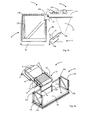
Fig. 2a illustrates the outmost end of the extendable conveyor with the platform in a top view; -
Fig. 2b illustrates the outmost end of the extendable conveyor with the platform in a side view; -
Fig. 3 illustrates the outmost end of the extendable conveyor with the platform in a three dimensional view; -
Fig. 4a illustrates in a side view the outmost end of the extendable conveyor with the platform in an operation position where the extendable conveyor is inclined and the platform is are horizontally aligned; -
Fig. 4b illustrates in a side view the outmost end of the extendable conveyor with the platform in an operation position where both the platform and the extendable conveyor are horizontally aligned; -
Fig. 5a illustrates side elements of the platform in an operating position; and -
Fig. 5b illustrates side elements of the platform in a parking position. -
Figs. 1a and 1b illustrate an embodiment of anextendable conveyor 1 in accordance with the present invention. Before presenting a detailed description of the preferred embodiments, some general explanations are made. - As mentioned in the outset, known extendable conveyors, typically have a base unit and multiple extendable conveyor sections which are nested within each other. The total length of the extendable conveyor can be adjusted by extending or retracting the nested extendable conveyor sections. The end of the extendable conveyor, i.e. the outmost extendable conveyor section, can move, for example, into a truck at a loading dock for loading or unloading goods. Such known extendable conveyors usually have a control panel at the front end (outmost end) of the extendable conveyor for controlling the conveyor.
- The control panel at the front end typically allows to control the extendable conveyor, in particular to start and stop conveying of articles, in order to load or unload articles, e.g. from a truck. Moreover, as mentioned in the outset, such a control typically allows to control the extension of the extendable conveyor.
- The inventors have recognized the benefit of a platform, such as a working platform, at the front end of the extendable conveyor such that personnel can stand on the platform for operating the extendable conveyor and/or for (un)loading articles.
- Due to the uncomfortable environment typically surrounding the working area of an extendable conveyor, it might also be difficult in future to attract people to work in the (un)loading zone at the extendable conveyor. Moreover, (un)loading zones are typically cramped and hazardous and, thus, the risk that personnel gets hurt is high.
- The inventors have also recognized that the comfort for personnel loading and unloading articles can be improved when the extendable conveyor includes at its end a platform on which personnel can stand, operate the extendable conveyor and/or (un)load articles.
- In the embodiments, an extendable conveyor for conveying articles comprises:
- a base unit,
- at least one mechanically extendable section, which is adjustably positionable incrementally between a fully nested position within the base unit and a fully extended position telescoped forwardly from the base unit, wherein one of the at least one mechanically extendable section is an outmost mechanically extendable section,
- a frame to which the base unit is connected and which is adapted to adjust an inclination of the base unit and of the at least one mechanically extendable section;
- a conveying surface for conveying articles extending at least partially on an upper side of the at least one mechanically extendable section;
- a platform, which is connected to the outmost mechanically extendable section; and
- an inclination adjuster adapted to adjust the inclination of the platform with respect to the inclination of the outmost mechanically extendable section.
- The base unit can be suspended in the frame. For example, a rear end of the base unit at which no mechanically extendable section is attached can be fix suspended at the frame, while a front end of the base being opposite to the rear end can be height adjustable suspended at the frame. Thereby, the height of the front end of the base unit can be adjusted. The rear end can be pivotable suspended at the frame, such that the rear end pivots when the height of the front end is adjusted. By adjusting the height of the front end of the base unit an inclination of the base unit and the at least one mechanically extendable section is adjusted.
- In some embodiments, the base unit and/or the frame is configured to be moveable on the floor in the direction of the mechanically extendable sections and/or transversely to this direction.
- The height of the front end of the base unit can be adjusted, for example, with a beam at which the front end of the base unit is suspended. The beam can be height adjusted, for example, with a hydraulic system, pneumatic system or the like as it is known to the skilled person.
- The conveying surface extends at least partially on an upper side of the at least one mechanically extendable section. In some embodiments the conveying surface also extends on the base unit. As known to the skilled person, the conveying surface can be formed by a belt or multiple rollers or the like. In the case of an extendable roller conveyor, in some embodiments, the conveyor is inclined during unloading such that articles are conveyed in the direction of the base unit due to gravitation force.
- In some embodiments, the extendable conveyor comprises two or more mechanically extendable sections, which are nested within each other and are disposed in a telescopic manner, such that they are adjustably positionable incrementally between a fully nested position within the base unit and a fully extended position telescoped forwardly from the base unit. The last mechanically extendable section at the end opposite to the base unit is also referred to as the outmost mechanically extendable section in the following (or briefly "outmost section"). The mechanically extendable sections between the base unit and the outmost mechanically extendable section are also referred to as intermediate mechanically extendable sections in the following (or briefly "intermediate section"). In embodiments where the extendable conveyor only comprises one mechanically extendable section, the "intermediate" and the "outmost" mechanically extendable section are the same.
- Typically, the mechanically extendable sections can be moved via a motor drive located in the base unit and, e.g. drive chains, interconnecting the sections with each other such that all mechanically extendable sections can perform a telescopic movement by driving the motor drive accordingly. The telescopic movement mechanic of an extendable conveyor is generally known to the skilled person.
- The platform can be pivotable connected to the outmost mechanically extendable section. For example, the outmost section can include a frame or the like to which the platform can be pivotable attached.
- The platform can include a bottom and, additionally, a front, and/or side elements, as also discussed below. It can be configured as a working platform for personnel.
- The inclination adjuster adapts the inclination of the platform with respect to the inclination of the outmost mechanically extendable section. For instance, the inclination of the platform can be such adjusted that the platform has the same inclination (or degree of inclination) independently from the inclination of the outmost section, such that, for example, the bottom of the platform is adjusted to be horizontal independent from the inclination of the outmost section to which the platform is connected. The platform can also have a predefined inclination with respect, for example, to the ground such that the predefined inclination is kept independent from the inclination of the outmost section.
- Hence, when the inclination of the base unit and the at least one mechanically extendable conveyor section is adjusted, the inclination adjuster also adjusts the inclination of the platform in accordance with a presetting, e.g. to keep the platform horizontal.
- In some embodiments, the adjustment of the inclination of the base unit and mechanically extendable conveyor sections and the adjustment of the inclination of the platform is (automatically) carried out simultaneously, such that the platform is hold at a predefined inclination (e.g. horizontal) during adjustment of the inclination of the base unit and mechanically extendable conveyor sections and the adjustment of the inclination of the platform.
- Hence, in some embodiments the inclination adjuster is adapted to adjust the inclination of the platform in (nearly) a horizontal orientation, irrespective which inclination the outmost section has. Thereby, personnel can safely stand on the platform also in cases where the extendable conveyor is inclined.
- The inclination adjuster can include an inclination sensor adapted to detect a deviation from a horizontal alignment of the platform and/or of the base unit and/or of at least one of the at least one mechanically extendable sections.
- The inclination sensor can include a gyro sensor and/or a tilt sensor or any other type of sensor which is capable of detecting an inclination.
- Generally, the inclination sensor can be located at any part of the extendable conveyor which is inclined in correspondence to the inclination of the base unit and the at least one mechanically extendable section, respectively. In some embodiments, the inclination sensor is located at the platform and, thus, can directly detect the inclination of the platform itself. In embodiments, where the inclination sensor is not located at the platform, the inclination of the platform can be indirectly determined, for example, on the basis of the knowledge of the angle between the platform and the outmost section to which the platform is mounted and the inclination detected by the inclination sensor.
- In some embodiments, the inclination adjuster includes a control which is located together with the inclination sensor in a housing at the platform. The control can include a processor (e.g. a microprocessor), and a memory. The control can be connected to the inclination sensor and receives and processes signals received from the inclination sensor in order to adjust the inclination of the platform accordingly.
- The inclination adjuster can include an actuator adapted to adjust an angle between the platform and the outmost mechanically extendable section. The actuator can include a linear actuator which can be driven electrically, hydraulically and/or pneumatically or the like.
- The actuator can be connected to the outmost section and the platform and it can be define an angle between the outmost section and the platform on the basis of its extension in a length direction. Thus, by adjusting the length of the actuator also the angle between the outmost section and the platform, and thereby the inclination of the platform can be adjusted.
- In some embodiments, the inclination adjuster (e.g. the control of the inclination adjuster) is adapted to control the actuator in response to the deviation from a horizontal alignment detected by the inclination sensor. The inclination sensor can output a respective inclination signal which directly or indirectly represents a deviation from a horizontal alignment. The inclination adjuster receives the inclination signal and controls the actuator such that, for example, the detected deviation is compensated and the platform is kept horizontally (or at a predefined inclination).
- In some embodiments, the platform includes at least one side element. The side element extends vertically from the bottom of the platform and, thus, builds a barrier for personnel standing on the platform hindering personnel from falling off the platform.
- The at least one side element can be pivotable from a working position into a parking position. In the working position it forms a side wall of the platform, while in the parking position it is, for example, parallel to a rear element of the platform, such that the sides of the platform are not limited by the side elements. Thereby, the bottom of the platform can be moved in places which have a height which is lower than the height of the side elements. Moreover, personnel can also enter the platform from the side, when the at least one side element is in its parking position.
- In some embodiments, the platform includes two side elements, wherein on each side of the platform one side element is located. The side elements define a working gap when being in the parking position. The working gap can be adapted to a width of the conveying surface. Thereby, the side elements do not hinder personnel (un)loading articles when the side elements are in its parking position. Moreover, the side elements typically have such a distance to each other that they can be pivoted from their operating to their parking position without being hindered by a worker standing on the platform.
- In some embodiments, the platform includes at least one storage bin. The storage bin can be attached to a rear wall of the platform and it can be adapted to receive tools or other items personnel uses/needs when working on the platform.
- In some embodiments, the outmost mechanically extendable section includes a (conveyor) control adapted to control the extension and/or the inclination of the base unit and the at least one mechanically extendable section. The control can be such located at the outmost mechanically extendable section that it can be operated from the platform, e.g. by personnel standing on the platform. Hence, personnel standing on the platform does not have to follow the movement of the extendable conveyor, but the platform moves together with the outmost section. As personnel can operate the extendable conveyor while standing on the platform there is also no risk that personnel is hurt by a movement of the extendable conveyor.
- In some embodiments, lights are located at the platform and/or at the outmost end in order to illuminate the platform.
- Returning to
Figs. 1a and 1b there is illustrated an embodiment of anextendable conveyor 1 in accordance with the present invention. Theextendable conveyor 1 has abase unit 2 and multiple mechanicallyextendable sections intermediate sections outmost section 4, which are mechanically extendable and which are nested within each other, as also explained above. A conveying surface in the form of abelt 6 extends over all mechanicallyextendable sections belt 6 is driven by a belt drive located in thebase unit 2. -
Fig. 1a illustrates theextendable conveyor 1 telescopically extended and in two different operating positions, whileFig. 1b illustrates theextendable conveyor 1 retracted and in a parking position. - The
base unit 2 is suspended in aframe 5. A rear end of thebase unit 2 is pivotable suspended in arear suspension 7a of the frame and a front end of thebase unit 2 is suspended in a front suspension 7b of the frame. The front suspension 7b is adapted to adjust the height such that it also adjusts the height of thebase unit 2 and, thus, also the inclination of theextendable conveyor 1, i.e. of thebase unit 2 and theintermediate sections outmost section 4. By adjusting the height of thebase unit 2, thebase unit 2 pivots around a horizontal axis at the suspension of therear suspension 7a of theframe 5. - An inclination adjustable platform, such as a
gyro platform 8 is attached at a pivot joint at theoutmost section 4 of theextendable conveyor 1. Thegyro platform 8 is kept in a horizontal orientation by aninclination adjuster 9, which will be described in further detail below. As can be taken fromFigs. 1a and 1b , thegyro platform 8 is kept horizontally independent from the inclination of thebase unit 2 and the intermediate 3a and 3b andoutmost sections 4. - As can also be taken from
Figs. 2a, 2b and3 , thegyro platform 8 has a bottom 8a and arear element 8b as well as twoside elements rear element 8b and theside elements rear element 8a is located adjacent to theoutmost end 4 and forms a "wall", i.e. a limitation at the rear end of thegyro platform 8. Hence, theside elements rear element 8a form a limitation at three sides of thegyro platform 8 in order to hinder personnel from falling off thegyro platform 8. Only the front side of thegyro platform 8 is open in this embodiment. However, in other embodiments, also the front side of thegyro platform 8 can be limited by respective (pivotable, removable) front elements. - Additionally, two
storage bins rear element 8b of thegyro platform 8. Personnel can put articles, tools or other items into thestorage bins 14 and 14b. - The
belt 6 does not extend to the outmost end of theoutmost section 4, but ends spaced apart therefrom. Next to the end of thebelt 6, a couple of pop-outrollers 16 are located, such that articles which are conveyed by thebelt 6 can roll over the pop-outrollers 16. - Moreover, on each side of the outmost section 4 a
sidepart 18 is provided which is adapted for controlling the extendable conveyor. Thesidepart 18 includes acontrol 15 which can have a keyboard, a navigation pad for controlling movement of thebelt 6 and of the wholeextendable conveyor 1 as well as elements for controlling other functions, such as switching on/off lights for illumination thegyro platform 8, etc. Thesideparts 18 with itscontrols 15 are mechanically connected to theoutmost section 4 and they are electrically connected to an internal electric and data bus system of theextendable conveyor 1, e.g. a modbus. - The
control 15 is such located that personnel on thegyro platform 8 can reach it and can control theextendable conveyor 1 while standing on thegyro platform 8. As thegyro platform 8 is kept horizontally by theinclination adjuster 9 independent from the inclination of thebase unit 2 and the intermediate 3a and 3b andoutmost sections 4, personnel can comfortable stand on thegyro platform 8. - As can also be taken from
Figs. 4a and4b , theinclination adjuster 9 has alinear actor 11 which is connected via a first pivot joint 19a to aframe 17 which is in turn mounted to the bottom ofoutmost section 4. At the opposite end,linear actor 11 is connected via a second pivot joint 19b at a lower portion of thegyro platform 8. Additionally, theinclination adjuster 9 has a control with an inclination sensor, such as a gyro sensor which are located in acommon housing 10 attached at therear element 8b of the gyro platform 8 (therefore, in the following the control and the gyro sensor are both denoted with reference sign "10"). Moreover, thegyro platform 8 is connected via a pivot joint 21 to the outmost end of theoutmost section 4. - The inclination adjuster 9 (i.e. its control 10) receives inclination signals from its
gyro sensor 10 and controls thelinear actuator 11 accordingly. The angle between thegyro platform 8 and theoutmost section 4 can be adjusted by adapting the length of thelinear actuator 11, as can also be taken fromFigs. 4a and4b . Hence, theinclination adjuster 9 provides an automatic and self-alignment of thegyro platform 8, such that thegyro platform 8 is kept horizontal (or at any other predefined inclination), as also discussed above. - In
Fig. 4a , theoutmost section 4 is inclined and thelinear actuator 11 has a longer extension compared to the situation ofFig. 4b where theoutmost section 4 is horizontal, and, thus, the angle between thegyro platform 8 and theoutmost section 4 is roughly 90°. Hence, by increasing the extension of thelinear actuator 11, the angle between thegyro platform 8 and theoutmost section 4 is increased and by decreasing the extension of thelinear actuator 11, the angle between thegyro platform 8 and theoutmost section 4 is decreased. Thus, by adapting the extension of thelinear actuator 11 in response to the inclination signal received from the gyro sensor, thecontrol 10 can keep thegyro platform 8 horizontally aligned. - For simplification reasons,
Fig. 4b showslinear actuator 11 in its nearly fully retracted position when theoutmost section 4 is horizontally aligned. Of course, the present invention is not limited in that regard and thelinear actuator 11 can be, for example, in its middle position (or any other position) when theoutmost section 4 is horizontally aligned, such that thelinear actuator 11 is able to further retract, for example, when theoutmost section 4 is raised, and, thus, the angle between thegyro platform 8 and theoutmost section 4 becomes smaller than 90°. Hence, in some embodiments, thelinear actuator 11 is adapted to hold thegyro platform 8, e.g. horizontally, in both cases that thebase unit 2, and, thus, theoutmost section 4 is lowered and raised. - As can also be taken from
Figs. 5a and5b , theside elements rear element 8b of thegyro platform 8. -
Fig. 5a shows theside elements gyro platform 8 and thereby limit the sides of thegyro platform 8. In the working position, theside elements biased bar - The
side elements Fig. 5b , in which they extend parallel to therear element 8b and, thus, do not form a limitation at the sides of thegyro platform 8.Magnets rear element 8 are such positioned that a vertical outer frame element of theside elements magnet 13 and 13b, respectively. Thereby,magnets side elements - When the
side elements gap 22 is provided between them which has a width which is similar to the width of the conveyingsurface 6. Hence, theside elements side elements - As is also shown in
Fig. 1b , as theside elements rear element 8b in the parking position, the bottom 8a of thegyro platform 8 needs less room than in the case that theside elements
Claims (15)
- An extendable conveyor for conveying articles, said conveyor comprising:a base unit (2);at least one mechanically extendable section (3a, 3b, 4), which is adjustably positionable incrementally between a fully nested position within the base unit (2) and a fully extended position telescoped forwardly from the base unit (2), wherein one of the at least one mechanically extendable section (3a, 3b, 4) is an outmost mechanically extendable section (4);a frame (5) to which the base unit (2) is connected and which is adapted to adjust an inclination of the base unit (2) and of the at least one mechanically extendable section (3a, 3b, 4);a conveying surface (6) for conveying articles extending at least partially on an upper side of the at least one mechanically extendable section (3a, 3b, 4);a platform (8), which is connected to the outmost mechanically extendable section (4); andan inclination adjuster (9) adapted to adjust the inclination of the platform (8) with respect to the inclination of the outmost mechanically extendable section (4).
- The extendable conveyor of claim 1, wherein the inclination adjuster (9) is adapted to adjust the inclination of the platform (8) in a horizontal orientation.
- The extendable conveyor of anyone of the preceding claims, wherein the inclination adjuster (9) includes an inclination sensor (10) adapted to detect a deviation from a horizontal alignment.
- The extendable conveyor of claim 3, wherein the inclination sensor (10) includes a gyro sensor.
- The extendable conveyor of claim 3 or 4, wherein the inclination sensor (10) is located at the platform (8).
- The extendable conveyor of claim 5, wherein the inclination adjuster (9) includes a control which is located together with the inclination sensor (10) in a housing at the platform (9).
- The extendable conveyor of anyone of the preceding claims, wherein the inclination adjuster (9) includes an actuator (11) adapted to adjust an angle between the platform (8) and the outmost mechanically extendable section (4).
- The extendable conveyor of anyone of claims 3 to 7, wherein the inclination adjuster (9) is adapted to control the actuator (11) in response to the deviation from a horizontal alignment detected by the inclination sensor (10).
- The extendable conveyor of anyone of the preceding claims, wherein the platform (8) includes at least one side element (12a, 12b).
- The extendable conveyor of claim 9, wherein the at least one side element (12a, 12b) is pivotable from a working position into a parking position.
- The extendable conveyor of claim 10, wherein the platform (8) includes two side elements (12a, 12b) defining a working gap (22) when being in the parking position.
- The extendable conveyor of claim 11, wherein the working gap (22) is adapted to a width of the conveying surface (6).
- The extendable conveyor of anyone of the preceding claims, wherein the platform (8) includes at least one storage bin (14a, 14b).
- The extendable conveyor of anyone of the preceding claims, wherein the outmost mechanically extendable section (4) includes a control (15) adapted to control the extension and/or the inclination of the base unit (2) and the at least one mechanically extendable section (3a, 3b, 4).
- The extendable conveyor of claim 14, wherein the control (15) is such located at the outmost mechanically extendable section (4) that it can be operated from the platform (8).
Priority Applications (2)
| Application Number | Priority Date | Filing Date | Title |
|---|---|---|---|
| EP14001979.5A EP2952457A1 (en) | 2014-06-06 | 2014-06-06 | Extendable conveyor comprising a work platform equipped with an inclination system |
| PCT/US2015/033281 WO2015187497A1 (en) | 2014-06-06 | 2015-05-29 | Extendable conveyors having a platform |
Applications Claiming Priority (1)
| Application Number | Priority Date | Filing Date | Title |
|---|---|---|---|
| EP14001979.5A EP2952457A1 (en) | 2014-06-06 | 2014-06-06 | Extendable conveyor comprising a work platform equipped with an inclination system |
Publications (1)
| Publication Number | Publication Date |
|---|---|
| EP2952457A1 true EP2952457A1 (en) | 2015-12-09 |
Family
ID=50942012
Family Applications (1)
| Application Number | Title | Priority Date | Filing Date |
|---|---|---|---|
| EP14001979.5A Withdrawn EP2952457A1 (en) | 2014-06-06 | 2014-06-06 | Extendable conveyor comprising a work platform equipped with an inclination system |
Country Status (2)
| Country | Link |
|---|---|
| EP (1) | EP2952457A1 (en) |
| WO (1) | WO2015187497A1 (en) |
Cited By (3)
| Publication number | Priority date | Publication date | Assignee | Title |
|---|---|---|---|---|
| GB2552025A (en) * | 2016-07-08 | 2018-01-10 | Sovex Ltd | Boom conveyor |
| GB2583037A (en) * | 2016-07-08 | 2020-10-14 | Sovex Ltd | Boom conveyor |
| US20240308777A1 (en) * | 2023-03-17 | 2024-09-19 | Fmh Conveyors Llc | Operator platform units for use with conveyors |
Citations (7)
| Publication number | Priority date | Publication date | Assignee | Title |
|---|---|---|---|---|
| WO1997039969A1 (en) * | 1996-04-24 | 1997-10-30 | Mannesmann Ag | Extendable trailer loader/unloader with user interface section |
| WO2002008098A2 (en) * | 2000-07-18 | 2002-01-31 | Siemens Aktiengesellschaft | Extendable gravity loader |
| JP2003221192A (en) * | 2002-01-30 | 2003-08-05 | Shin Meiwa Ind Co Ltd | Workbench horizontal control system for aerial work platforms |
| WO2006068443A1 (en) | 2004-12-22 | 2006-06-29 | Loteco, Inc. | Telescopic conveyor |
| EP1826154A1 (en) * | 2006-02-24 | 2007-08-29 | Gawronski GmbH Industrievertretungen | Conveyor belt for transporting articles |
| DE102010005267A1 (en) | 2010-01-20 | 2011-07-21 | nobab gmbh, 70825 | Conveying device for use with attachment device for packaged goods distribution system for packaged goods, has conveying head which has receiving area for manual placing of packaged goods |
| CN103802085A (en) * | 2014-03-01 | 2014-05-21 | 国家电网公司 | Multifunctional movable platform special for overhauling and maintaining and maintaining method |
-
2014
- 2014-06-06 EP EP14001979.5A patent/EP2952457A1/en not_active Withdrawn
-
2015
- 2015-05-29 WO PCT/US2015/033281 patent/WO2015187497A1/en not_active Ceased
Patent Citations (7)
| Publication number | Priority date | Publication date | Assignee | Title |
|---|---|---|---|---|
| WO1997039969A1 (en) * | 1996-04-24 | 1997-10-30 | Mannesmann Ag | Extendable trailer loader/unloader with user interface section |
| WO2002008098A2 (en) * | 2000-07-18 | 2002-01-31 | Siemens Aktiengesellschaft | Extendable gravity loader |
| JP2003221192A (en) * | 2002-01-30 | 2003-08-05 | Shin Meiwa Ind Co Ltd | Workbench horizontal control system for aerial work platforms |
| WO2006068443A1 (en) | 2004-12-22 | 2006-06-29 | Loteco, Inc. | Telescopic conveyor |
| EP1826154A1 (en) * | 2006-02-24 | 2007-08-29 | Gawronski GmbH Industrievertretungen | Conveyor belt for transporting articles |
| DE102010005267A1 (en) | 2010-01-20 | 2011-07-21 | nobab gmbh, 70825 | Conveying device for use with attachment device for packaged goods distribution system for packaged goods, has conveying head which has receiving area for manual placing of packaged goods |
| CN103802085A (en) * | 2014-03-01 | 2014-05-21 | 国家电网公司 | Multifunctional movable platform special for overhauling and maintaining and maintaining method |
Cited By (12)
| Publication number | Priority date | Publication date | Assignee | Title |
|---|---|---|---|---|
| GB2552025A (en) * | 2016-07-08 | 2018-01-10 | Sovex Ltd | Boom conveyor |
| WO2018007781A1 (en) * | 2016-07-08 | 2018-01-11 | Sovex Ltd | Boom conveyor |
| CN109476421A (en) * | 2016-07-08 | 2019-03-15 | 索维克斯有限公司 | Cantilever conveyer |
| US10669108B2 (en) | 2016-07-08 | 2020-06-02 | Transnorm System Gmbh | Boom conveyor |
| GB2552025B (en) * | 2016-07-08 | 2020-08-12 | Sovex Ltd | Boom conveyor |
| GB2583037A (en) * | 2016-07-08 | 2020-10-14 | Sovex Ltd | Boom conveyor |
| GB2583037B (en) * | 2016-07-08 | 2021-03-03 | Sovex Ltd | Boom conveyor |
| AU2017294130B2 (en) * | 2016-07-08 | 2022-10-06 | Honeywell Control Systems Ltd. | Boom conveyor |
| US11655109B2 (en) | 2016-07-08 | 2023-05-23 | Transnorm System Gmbh | Boom conveyor |
| US11685617B2 (en) | 2016-07-08 | 2023-06-27 | Transnorm System Gmbh | Boom conveyor |
| US20240308777A1 (en) * | 2023-03-17 | 2024-09-19 | Fmh Conveyors Llc | Operator platform units for use with conveyors |
| US12583685B2 (en) * | 2023-03-17 | 2026-03-24 | Fmh Conveyors Llc | Operator platform units for use with conveyors |
Also Published As
| Publication number | Publication date |
|---|---|
| WO2015187497A1 (en) | 2015-12-10 |
Similar Documents
| Publication | Publication Date | Title |
|---|---|---|
| EP2634117B1 (en) | Extendable conveyor with modular front end | |
| US9776511B2 (en) | Vehicle alignment systems for loading docks | |
| US9776801B2 (en) | System with telescopic conveyor and method therefor | |
| EP2563695B1 (en) | Telescopic belt conveyor | |
| EP1834922B1 (en) | Industrial truck with a mast | |
| KR101580528B1 (en) | Trolley For Structure Assembly | |
| WO2008147550A1 (en) | System and method for automated truck loading | |
| US20150314988A1 (en) | Lockable Lift Device and Method | |
| KR101934669B1 (en) | Mobile elevated work platform with outrigger | |
| CN109311609A (en) | Pedestrian vehicle warning system for loading docks | |
| US10421615B2 (en) | Workpiece singulator with adjustable stair depth | |
| CN106120517A (en) | There is the building machinery of the lifting device for charging process | |
| WO2015187497A1 (en) | Extendable conveyors having a platform | |
| US11414115B2 (en) | Multi-stage load adjustment type moving cart | |
| AU2017294130B2 (en) | Boom conveyor | |
| KR101478726B1 (en) | lifting device for truck | |
| KR20210142239A (en) | conveyor system | |
| KR20140140156A (en) | Lifting Apparatus for Ship | |
| EP2923976B1 (en) | Device and method for automatically loading objects | |
| JP7050429B2 (en) | Follow-up trolleys and trolleys | |
| US20240051449A1 (en) | Cargo decking elevation system | |
| KR101920441B1 (en) | Apparatus for protecting deflection of ball screw | |
| EP4446252A2 (en) | Load handling sensors for a material handling vehicle | |
| JP2019122203A (en) | Control panel assembly device | |
| US20210070555A1 (en) | Arrangement For Processing a Shipment |
Legal Events
| Date | Code | Title | Description |
|---|---|---|---|
| PUAI | Public reference made under article 153(3) epc to a published international application that has entered the european phase |
Free format text: ORIGINAL CODE: 0009012 |
|
| AK | Designated contracting states |
Kind code of ref document: A1 Designated state(s): AL AT BE BG CH CY CZ DE DK EE ES FI FR GB GR HR HU IE IS IT LI LT LU LV MC MK MT NL NO PL PT RO RS SE SI SK SM TR |
|
| AX | Request for extension of the european patent |
Extension state: BA ME |
|
| 17P | Request for examination filed |
Effective date: 20160407 |
|
| RBV | Designated contracting states (corrected) |
Designated state(s): AL AT BE BG CH CY CZ DE DK EE ES FI FR GB GR HR HU IE IS IT LI LT LU LV MC MK MT NL NO PL PT RO RS SE SI SK SM TR |
|
| TPAC | Observations filed by third parties |
Free format text: ORIGINAL CODE: EPIDOSNTIPA |
|
| STAA | Information on the status of an ep patent application or granted ep patent |
Free format text: STATUS: THE APPLICATION HAS BEEN WITHDRAWN |
|
| 18W | Application withdrawn |
Effective date: 20161017 |