EP2952394A1 - Gas generator - Google Patents
Gas generator Download PDFInfo
- Publication number
- EP2952394A1 EP2952394A1 EP14745469.8A EP14745469A EP2952394A1 EP 2952394 A1 EP2952394 A1 EP 2952394A1 EP 14745469 A EP14745469 A EP 14745469A EP 2952394 A1 EP2952394 A1 EP 2952394A1
- Authority
- EP
- European Patent Office
- Prior art keywords
- chamber housing
- ignition device
- gas
- base plate
- plate portion
- Prior art date
- Legal status (The legal status is an assumption and is not a legal conclusion. Google has not performed a legal analysis and makes no representation as to the accuracy of the status listed.)
- Granted
Links
Images

Classifications
-
- B—PERFORMING OPERATIONS; TRANSPORTING
- B60—VEHICLES IN GENERAL
- B60R—VEHICLES, VEHICLE FITTINGS, OR VEHICLE PARTS, NOT OTHERWISE PROVIDED FOR
- B60R21/00—Arrangements or fittings on vehicles for protecting or preventing injuries to occupants or pedestrians in case of accidents or other traffic risks
- B60R21/02—Occupant safety arrangements or fittings, e.g. crash pads
- B60R21/16—Inflatable occupant restraints or confinements designed to inflate upon impact or impending impact, e.g. air bags
- B60R21/26—Inflatable occupant restraints or confinements designed to inflate upon impact or impending impact, e.g. air bags characterised by the inflation fluid source or means to control inflation fluid flow
- B60R21/268—Inflatable occupant restraints or confinements designed to inflate upon impact or impending impact, e.g. air bags characterised by the inflation fluid source or means to control inflation fluid flow using instantaneous release of stored pressurised gas
- B60R21/272—Inflatable occupant restraints or confinements designed to inflate upon impact or impending impact, e.g. air bags characterised by the inflation fluid source or means to control inflation fluid flow using instantaneous release of stored pressurised gas with means for increasing the pressure of the gas just before or during liberation, e.g. hybrid inflators
-
- B—PERFORMING OPERATIONS; TRANSPORTING
- B01—PHYSICAL OR CHEMICAL PROCESSES OR APPARATUS IN GENERAL
- B01J—CHEMICAL OR PHYSICAL PROCESSES, e.g. CATALYSIS OR COLLOID CHEMISTRY; THEIR RELEVANT APPARATUS
- B01J7/00—Apparatus for generating gases
-
- B—PERFORMING OPERATIONS; TRANSPORTING
- B60—VEHICLES IN GENERAL
- B60R—VEHICLES, VEHICLE FITTINGS, OR VEHICLE PARTS, NOT OTHERWISE PROVIDED FOR
- B60R21/00—Arrangements or fittings on vehicles for protecting or preventing injuries to occupants or pedestrians in case of accidents or other traffic risks
- B60R21/02—Occupant safety arrangements or fittings, e.g. crash pads
- B60R21/16—Inflatable occupant restraints or confinements designed to inflate upon impact or impending impact, e.g. air bags
- B60R21/26—Inflatable occupant restraints or confinements designed to inflate upon impact or impending impact, e.g. air bags characterised by the inflation fluid source or means to control inflation fluid flow
- B60R21/268—Inflatable occupant restraints or confinements designed to inflate upon impact or impending impact, e.g. air bags characterised by the inflation fluid source or means to control inflation fluid flow using instantaneous release of stored pressurised gas
- B60R21/274—Inflatable occupant restraints or confinements designed to inflate upon impact or impending impact, e.g. air bags characterised by the inflation fluid source or means to control inflation fluid flow using instantaneous release of stored pressurised gas characterised by means to rupture or open the fluid source
Definitions
- the present invention relates to a gas generator used in a restraining device of an airbag system for a vehicle or the like.
- a gas generator that uses a pressurized gas generally employs a structure in which an opening portion of a bottle with the pressurized gas sealed therein is closed by a closing member and the pressurized gas is discharged by rupturing the closing member during activation.
- the gas generator employs such a structure that the time elapsed from activation (for example, when an ignition current flows in an electric igniter) until the start of gas discharge decreases as much as possible and the pressurized gas can be discharged quickly (a restraining device or the like is activated quickly).
- US-A No. 2006/037662 discloses a gas generator that uses a pressurized gas, in which an initiator 20 is attached to one end of a housing 16, and a projectile 22 is attached to a cylindrical body 82 filled with an ignition charge.
- a chamber 38 filled with a pressurized gas and the initiator 20 are separated from each other by a closure member 14, and the projectile 22 abuts against the closure member 14.
- US-B No. 7192052 discloses a gas generator that uses a pressurized gas, in which the gas filled in a bottle 14 is sealed by a burst disc 84 attached to an opening 82. Moreover, chamber opener assembly 90 is disposed in the burst disc 84.
- the opener assembly 90 has a needle 94 at a tip end thereof.
- an initiator 32 ignites to effect ignition of a gas generant pyrotechnic material 54
- the opener assembly 90 moves and the needle 94 passes through the burst disc 84.
- the tip end of the needle 94 is a hollow tubular member of which the periphery is inclined.
- the present invention provides a gas generator (10), including
- activation of the initiator 20 causes the projectile 22 to move and rupture the closure member 14, whereby the pressurized gas is discharged to the outside from a gas outlet 18.
- the time elapsed from activation (activation of the igniter 20) until the gas is discharged may become prolonged. In this regard, there is still room for further improvement.
- the present invention provides a gas generator capable of maintaining high performance during the service life of a vehicle and discharging gas in an earlier initial stage of activation without producing fragments of a closing member when applied to a restraining device of an airbag system of a vehicle or the like.
- the multifunctional member used in the gas generator according to the present invention functions to rupture the closing member, to hold the gas generating agent, and to secure the gas discharge path.
- the multifunctional member has the base plate portion and the cylindrical wall portion extended from one surface of the base plate portion. Moreover, an end of the cylindrical wall portion on an opposite side of the base plate portion is an opening portion having an inclined end surface.
- the presence of the multifunctional member enables to exhibit functions (I) and (II) below, and additionally a function (III).
- the pressurized gas chamber housing Before activation (before activation of an ignition device; the same applies hereinafter), the pressurized gas chamber housing is filled with a pressurized gas under high pressure.
- the multifunctional member (the base plate portion and the cylindrical wall portion having the inclined end surface) is moved in the axial direction (toward the closing member), whereby the closing member is ruptured by the inclined end surface of the opening portion of the cylindrical wall portion and the flow path for the pressurized gas is opened.
- the cylindrical wall portion Since the cylindrical wall portion has the inclined end surface on the opening portion thereof, the cylindrical wall portion has a longest portion and a shortest portion. Although the longest portion of the inclined end surface has a sharp tip end, the shortest portion does not have a sharp tip end. During activation, the closing member is ruptured by the tip end of the longest portion.
- the moving distance in the axial direction of the multifunctional member before and after activation is restricted by the movement restriction means such that the longest portion of the cylindrical wall portion passes through the closing member, but the shortest portion of the cylindrical wall portion does not pass through the closing member.
- the form of the closing member is not particularly limited as long as the closing member closes the space between the ignition device chamber housing and the pressurized gas chamber housing.
- the closing member can be a disc member (for example, a rupture plate 40 in Fig. 3 of JP-A No. 2003-226222 ) that is welded and fixed, from the pressurized gas chamber housing side, to an annular plate portion (an annular protrusion) that protrudes inward from one of the ignition device chamber housing and the pressurized gas chamber housing.
- a disc member for example, a rupture plate 40 in Fig. 3 of JP-A No. 2003-226222
- the disc member serving as the closing member is deformed in a bowl-like shape that protrudes toward the ignition device chamber housing by receiving pressure from the inside of the pressurized gas chamber housing.
- the multifunctional member is disposed so that the inclined end surface does not make contact with the closing member.
- the closing member can be also a bottom plate member (for example, a rupture plate 10 in Fig. 4 of JP-A No. 2010-018132 ) that is formed to be integrated with one of the ignition device chamber housing and the pressurized gas chamber housing such that a central portion thereof is ruptured during activation and a peripheral portion thereof remains in a state of being integrated with one of the ignition device chamber housing and the pressurized gas chamber housing (in the same form as the annular plate portion described above).
- a fragile portion may be formed in the central portion.
- the movement restriction means may be configured such that one or both of the base plate portion and the cylindrical wall portion of the multifunctional member makes contact with another member to stop movement of the multifunctional member.
- a protrusion may be formed on the base plate portion, the cylindrical wall portion and the ignition device chamber housing so that these protrusions make contact with each other to suppress movement of the multifunctional member.
- the base plate portion abuts against the inner wall surface of the ignition device chamber housing, and the cylindrical wall portion has an outer diameter smaller than an outer diameter of the base plate portion.
- the plenum chamber is formed.
- the cylindrical wall portion of the multifunctional member is positioned in the plenum chamber.
- the plenum chamber communicates with the gas generating agent charging chamber that is charged with the gas generating agent.
- a discharge path of the combustion gas generated in the gas generating agent charging chamber and a discharge path of the pressurized gas are secured.
- the gas generating agent charging chamber and the plenum chamber may communicate with each other before activation.
- the size of the communicating portion that makes communication between the gas generating agent charging chamber and the plenum chamber is set to such an opening area that the combustion gas generates a differential or a gradient in pressure between the gas generating agent charging chamber and the plenum chamber.
- an airbag can be inflated in a reliable and quick manner.
- the multifunctional member is moved by pressure by the combustion gas to rupture the closing member.
- the gas may flow directly into the plenum chamber through the gap between the shortest portion and the portion of the closing member turned up toward the pressurized gas chamber housing to be discharged from the gas discharge port.
- the function to hold the gas generating agent may be obtained by the multifunctional member used in the gas generator according to the present invention or may be obtained by another member.
- the function to hold the gas generating agent may be exhibited by the multifunctional member as follows:
- the gas generator When the gas generator is mounted on a vehicle, vibration is applied to the gas generator over a long period of time. If the gas generating agent is insufficiently fixed, the gas generating agents may rub against each other and become pulverized.
- the multifunctional member used in the gas generator of the present invention is preferably configured as follows:
- the gas generator of the present invention preferably includes at least one of the followings as the movement restriction means for the multifunctional member.
- Movement of the multifunctional member is restricted within the range of the first protrusion and the second protrusion, and the closing member is ruptured by the multifunctional member that has moved within this restricted range.
- the gas generator according to present invention maintains high performance during a service life of a vehicle when applied to a restraining device of an airbag system of the vehicle or the like.
- a gas generator 10 includes an ignition device chamber housing 20 and a pressurized gas chamber housing 40 which are joined to form an outer-shell container.
- a closing member 12 closes between the ignition device chamber housing 20 and the pressurized gas chamber housing 40.
- a circumference edge of the closing member 12 is welded and fixed, from the pressurized gas chamber housing 40, to an annular plate portion 13 that protrudes inward from an inner wall surface of the ignition device chamber housing 20.
- the annular plate portion 13 may be one that protrudes inward from the inner wall surface of the pressurized gas chamber housing 40.
- the closing member 12 may be one that is integrated with one of the ignition device chamber housing 20 and the pressurized gas chamber housing 40 (for example, a bottom plate member of any one of the housings).
- the closing member 12 has a disc shape (a flat-plate shape) before assembling, and is deformed in a bowl-like shape in response to pressure of a pressurized gas inside the pressurized gas chamber housing 40.
- An opening portion (the opening portion opposite to the closing member 12) of the ignition device chamber housing 20 is closed by an electric igniter 25 fixed thereto.
- the electric igniter 25 fixed to a collar is fixed by being held from both sides in the X-axis direction by an inward annular protrusion 21a formed on an circumferential wall portion 21 of the ignition device chamber housing 20 and an opening end portion 22 crimped inward.
- a multifunctional member 30 having the functions (I) to (III) described above is arranged in the ignition device chamber housing 20.
- the multifunctional member 30 has a base plate portion 31 and a cylindrical wall portion 32 extended from one surface of the base plate portion 31.
- the base plate portion 31 is movable and in contact with the inner wall surface (a circumferential wall portion) 21 of the ignition device chamber housing 20, and has a first through-hole 33 in a thickness direction thereof.
- the first through-hole 33 may be closed by an aluminum adhesive tape or the like that is readily broken.
- the first through-holes 33 are formed at the center of the base plate portion 31 to enable communication with the inner space (a plenum chamber 36) of the cylindrical wall portion 32.
- the first through-holes 33 may be formed near the peripheral edge of the base plate portion 31 to enable communication with the plenum chamber 36.
- the number of the first through-hole 33 is not particularly limited. Moreover, a recess may be formed in the peripheral edge of the base plate portion 31 to form a gap between the recess and the inner wall surface 21 of the ignition device chamber housing 20, so that the gap serves as the first through-hole.
- the cylindrical wall portion 32 has the same central axis X as the base plate portion 31, and an outer diameter of the cylindrical wall portion 32 is smaller than an outer diameter of the base plate portion 31.
- the cylindrical wall portion 32 has a plurality of second through-holes 34 in the thickness direction thereof.
- An annular end surface (an end surface close to the closing member 12) of the opening portion of the cylindrical wall portion 32 is configured as an inclined end surface 35 that is inclined with respect to the base plate portion 31.
- the cylindrical wall portion 32 having the inclined end surface 35 has the longest portion 35a and the shortest portion 35b, and a tip end portion including the longest portion 35a has a sharp edge.
- the length between the tip of the longest portion 35a and the base plate portion 31 is a largest length (Lmax).
- the length between the tip of the shortest portion 35b and the base plate portion 31 is a smallest length (Lmin).
- the ratio, Lmin/Lmax, of the length (Lmin) of the shortest portion 35b to the length (Lmax) of the longest portion 35a of the cylindrical wall portion 32 is between 20% and 75%.
- the inclined end surface 35 is a continuous inclined end surface (the cross-section of the end surface is an inclined straight line), a portion (one or multiple portions) between the longest portion 35a and the shortest portion 35b may be depressed toward the base plate portion 31.
- the inclined end surface 35 (the longest portion 35a) of the cylindrical wall portion 32 is not in contact with the closing member 12 before activation.
- a protrusion (a first protrusion) 21b is formed on the inner wall surface 21 of the ignition device chamber housing 20. Before activation, the base plate portion 31 of the multifunctional member 30 abuts against the protrusion (the first protrusion) 21b to prevent movement toward the igniter 25.
- the multifunctional member 30 is temporarily clamped by a temporary fixing means, so that the multifunctional member 30 does not move toward the closing member 12 before activation (that is, the multifunctional member 30 does not move in response to vibration from a vehicle to which the gas generator is attached) and that the multifunctional member 30 ruptures the closing member 12 by moving toward the closing member 12 in response to the pressure of the combustion gas during activation.
- An example of the temporary fixing means can be a protrusion which holds the base plate portion 31 together with the protrusion (the first protrusion) 21b in the thickness direction, in which the inwardly protruding length of the protrusion is smaller than the protrusion (the first protrusion) 21b and the width of the protrusion is smaller than the protrusion 21b.
- a shallow and narrow annular groove may be formed on the circumferential surface of the base plate portion 31, and a protrusion corresponding to the annular groove on the circumferential surface may be formed on the inner wall surface 21 so that a combination of the annular groove and the protrusion provides the temporary fixing function.
- a step (a second protrusion) 26 is arranged between the first protrusion 21b and the closing member 12.
- a combination of the first protrusion 21b and the step (the second protrusion) 26 forms a movement restriction means that restricts a moving distance (a moving range) of the multifunctional member 30 in the X-axis direction.
- the moving distance (r1 in (a) in Fig. 3 ) restricted by the combination of the protrusion (the first protrusion) 21b and the step (the second protrusion) 26 is set to such a distance that the longest portion 35a of the cylindrical wall portion 32 passes through the closing member 12, preferably, passes through a boundary surface 50 between the closing member 12 and the annular plate portion 13 (to move a distance of r2 or more) and that the shortest portion 35b of the cylindrical wall portion 32 does not pass through the boundary surface 50 (to move a distance equal to r3 or smaller).
- boundary surface 50 is an imaginary surface that passes through the boundary between the closing member 12 and the annular plate portion 13.
- r1, r2, and r3 satisfy a relation of r1>r2 and r1 ⁇ r3, and can be adjusted appropriately within such a range that the relation is satisfied.
- r1/r2 may be set between 1.3 and 4
- r3/r1 may be set between 1.3 and 4.
- a plurality of gas discharge ports 27 are formed, between the step 26 and the closing member 12, in the inner wall surface 21 of the ignition device chamber housing 20.
- the plurality of gas discharge ports 27 are closed from the inside by an aluminum adhesive tape or the like.
- the space enclosed by the base plate portion 31, the inner wall surface 21 and the closing member 12 is the plenum chamber 36 that forms the gas discharge path. Since the cylindrical wall portion 32 is positioned inside the plenum chamber 36, both the inside and the outside of the cylindrical wall portion 32 are the plenum chamber 36. The gas discharge port 27 faces the plenum chamber 36.
- the space enclosed by the base plate portion 31, the igniter 25 and the inner wall surface 21 is a gas generating agent charging chamber 37, and a molded article of known gas generating agent 38 is charged in the gas generating agent charging chamber 37.
- An amount of the molded article of the gas generating agent 38 used is determined appropriately according to the type of the gas generator.
- the pressurized gas chamber housing 40 is filled with a gas such as argon or helium under high pressure.
- the gas is filled from a gap between a pore and a pin 42 inserted into the pore on a bottom surface 41. After the gas is filled, the pore is closed by welding the bottom surface 41 and the pin 42.
- the igniter 25 When the igniter 25 is activated, the molded article of gas generating agent 38 in the gas generating agent charging chamber 37 is ignited and combusted to generate combustion gas.
- the generated combustion gas immediately enters the plenum chamber 36 inside the cylindrical wall portion 32 through the first through-hole 33 and enters the plenum chamber 36 outside the cylindrical wall portion 32 through the second through-hole 34 to break the moisture-proofing seal tape. After that, the gas is discharged from the gas discharge port 27 to inflate an airbag.
- the gas can be quickly discharged with the activation of the gas generator and the activation (deployment) of a restraining device such as an airbag can be quickly started.
- the base plate portion 31 stops after moving from the protrusion (the first protrusion) 21b to the step (the second protrusion) 26.
- the longest portion 35a having a sharp edge passes through the boundary surface 50, whereby the closing member 12 is ruptured and opened from the annular plate portion 13 (r1>r2 in (a) in Fig. 3 , and the inner diameter of the annular plate portion 13 is slightly larger than the outer diameter of the cylindrical wall portion 32).
- the shortest portion 35b also collides with the closing member 12, the shortest portion 35b does not pass through the boundary surface 50 (r1 ⁇ r3 in (a) in Fig. 3 ), preferably, does not pass through the closing member 12, the shortest portion 35b does not have a sharp edge, and therefore, the closing member 12 that the shortest portion 35b faces is not ruptured.
- the closing member 12 When the multifunctional member 30 collides with the closing member 12 and the pressure inside the plenum chamber 36 has increased, the closing member 12 is ruptured to be turned up toward the pressurized gas chamber housing 40 as illustrated in (b) in Fig. 3 . After that, since the gas inside the pressurized gas chamber housing 40 is discharged and the pressure decreases, the closing member 12 maintains this state.
- the moving distance (r3) of the shortest portion 35b may be adjusted so that the shortest portion 35b abuts against the opened and turned-up closing member 12, or the moving distance (r3) may be adjusted so that a gap serving as the gas discharge path is formed between the shortest portion 35b and the opened and turned-up closing member 12.
- the gas inside the pressurized gas chamber housing 40 passes through an opening formed by the ruptured closing member 12, the second through-hole 34 and the plenum chamber 36 outside the cylindrical wall portion 32, and is discharged from the gas discharge port 27 to inflate an airbag.
- the gas inside the pressurized gas chamber housing 40 can directly enter the plenum chamber 36 outside the cylindrical wall portion 32 and be discharged form the gas discharge port 27 to inflate the airbag.
- Fig. 4 is a perspective view of a multifunctional member 130 used in a gas generator.
- the multifunctional member 130 has the same functions and operations as the multifunctional member 30 in Fig. 1 except that the multifunctional member 30 has a shape different from the inclined end surface 135.
- the multifunctional member 130 has a base plate portion 131 and a cylindrical wall portion 132 extended from one surface of the base plate portion 131.
- the base plate portion 131 has a first through-hole similarly to the base plate portion 31 of Fig. 1 .
- the cylindrical wall portion 132 has an inclined end surface 135 that has a wavy convex and concave surface, and has a longest portion 135a and a shortest portion 135b. A convex portion is formed between the longest portion 135a and the shortest portion 135b.
- a concave portion of the inclined end surface 135 functions, together with the second through-hole 134, as a gas discharge path along which the gas is discharged from the pressurized gas chamber housing 40.
- Fig. 5 is a perspective view of a multifunctional member 230 used in a gas generator.
- the multifunctional member 230 has a base plate portion 231 and a cylindrical wall portion 232 extended from one surface of the base plate portion 231.
- the base plate portion 231 has a first through-hole similarly to the base plate portion 31 in Fig. 1 .
- the cylindrical wall portion 232 has an opening end surface that is configured as an inclined end surface 235 and has a longest portion 235a and a shortest portion 235b.
- the longest portion 235a has a smallest thickness and the shortest portion 235b has a largest thickness (Tmax).
- a tip end of the longest portion 235a having the smallest thickness has a sharp edge and functions to rupture the closing member 12 when the multifunctional member 230 is moved in the X-axis direction during activation.
- the shortest portion 235b having the largest thickness collides with the closing member 12 to restrict further movement of the multifunctional member 230 when the multifunctional member 230 is moved in the X-axis direction during activation.
- the step 26 that restricts the movement of the multifunctional member 230 may not be needed.
- Fig. 6 is a cross-sectional view in the axial direction of a multifunctional member 330 used in a gas generator.
- the multifunctional member 330 has a base plate portion 331 and a cylindrical wall portion 332 extended from one surface of the base plate portion 331.
- the base plate portion 331 has a first through-hole similarly to the base plate portion 31 in Fig. 1 .
- the cylindrical wall portion 332 has an opening end surface that is configured as an inclined end surface 335 and has a longest portion 335a and a shortest portion 335b.
- a protrusion 337 protruding outward is formed on an outer wall surface of the longest portion 335a of the cylindrical wall portion 332.
- the protrusion 337 collides with the annular plate portion 13 to which the closing member 12 is welded and fixed so as to restrict further movement of the multifunctional member 330 when the multifunctional member 330 is moved in the X-axis direction during activation.
- the step 26 that restricts the movement of the multifunctional member 330 may not be needed.
- a specific embodiment of the gas generator according to the present invention is not limited to the present embodiments as long as the problem described above can be solved.
- different embodiments can be adopted with respect to the shape of the multifunctional member, the annular protrusion and the step formed on the ignition device chamber housing, and the like in order to realize similar functions.
Landscapes
- Physics & Mathematics (AREA)
- Fluid Mechanics (AREA)
- Engineering & Computer Science (AREA)
- Mechanical Engineering (AREA)
- Chemical & Material Sciences (AREA)
- Organic Chemistry (AREA)
- Chemical Kinetics & Catalysis (AREA)
- Air Bags (AREA)
Abstract
Description
- The present invention relates to a gas generator used in a restraining device of an airbag system for a vehicle or the like.
- A gas generator that uses a pressurized gas generally employs a structure in which an opening portion of a bottle with the pressurized gas sealed therein is closed by a closing member and the pressurized gas is discharged by rupturing the closing member during activation.
- Furthermore, it is desirable that the gas generator employs such a structure that the time elapsed from activation (for example, when an ignition current flows in an electric igniter) until the start of gas discharge decreases as much as possible and the pressurized gas can be discharged quickly (a restraining device or the like is activated quickly).
-
US-A No. 2006/037662 discloses a gas generator that uses a pressurized gas, in which aninitiator 20 is attached to one end of a housing 16, and aprojectile 22 is attached to a cylindrical body 82 filled with an ignition charge. Achamber 38 filled with a pressurized gas and theinitiator 20 are separated from each other by a closure member 14, and theprojectile 22 abuts against the closure member 14. -
US-B No. 7192052 discloses a gas generator that uses a pressurized gas, in which the gas filled in a bottle 14 is sealed by a burst disc 84 attached to an opening 82. Moreover, chamber opener assembly 90 is disposed in the burst disc 84. - The opener assembly 90 has a needle 94 at a tip end thereof. When an
initiator 32 ignites to effect ignition of a gas generant pyrotechnic material 54, the opener assembly 90 moves and the needle 94 passes through the burst disc 84. The tip end of the needle 94 is a hollow tubular member of which the periphery is inclined. - The present invention provides a gas generator (10), including
- a cylindrical ignition device chamber housing (20) provided with a gas discharge port (27), accommodating an igniter(25) and a gas generating agent(38), a cylindrical pressurized gas chamber housing (40) filled with pressurized gas, the ignition device chamber housing (20) joining to the pressurized gas chamber housing (40) to form an outer container,
- a closing member(12) closing between the ignition device chamber housing (20) and the pressurized gas chamber housing (40),
- a multifunctional member(30), movable in the axial direction during activation, being disposed inside the ignition device chamber housing (20) together with the igniter(25) and the gas generating agent(38),
- the igniter(25) closing the opening portion of the ignition device chamber housing (20) and being fixed thereto,
- the multifunctional member(30) having a base plate portion (31) and a cylindrical wall portion (32) extending from one surface of the base plate portion (31), an annular end surface of the opening portion of the cylindrical wall portion (32) including an inclined end surface(35) inclined with respect to the base plate portion (31), the inclined end surface(35) being arranged not in contact with the closing member(12),
- a plenum chamber(36), being enclosed by the ignition device chamber housing (20), the base plate portion (31) and the closing member(12),
- the gas discharge port (27) formed in a circumferential wall portion, of the ignition device chamber housing (20), to face the plenum chamber(36),
- a gas generating agent charging chamber(37), charged with a gas generating agent(38), enclosed by the base plate portion (31), the igniter(25) and an inner wall surface(21) of the ignition device chamber housing, the plenum chamber(36) and the gas generating agent charging chamber(37) communicating with each other,
- the multifunctional member(30) moving in the axial direction by internal pressure increase due to combustion gas generated by combustion of the gas generating agent(38) in the gas generating agent charging chamber(37) to break the closing member(12) with the inclined end surface(35) of the cylindrical wall portion (32), and thereby, obtaining a gas discharge path, and
- a movement restriction means restricting a moving distance in the axial direction of the multifunctional member(30) before and after activation such that a longest portion of the cylindrical wall portion (32) passes through the closing member(12) but a shortest portion of the cylindrical wall portion (32) does not pass through the closing member(12).
- The present invention will become more fully understood from the detailed description given hereinbelow and the accompanying drawings which are given by way of illustration only, and thus are no limitative of the present invention and wherein:
-
- [
Fig. 1] Fig. 1 shows a cross-sectional view in the axial direction of a gas generator according to the present invention; - [
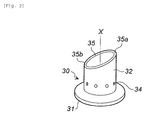
Fig. 2] Fig. 2 shows a perspective view of a multifunctional member ofFig. 1 ; - [
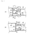
Fig. 3] Fig. 3 , in (a) and (b), shows a partial cross-sectional view illustrating an activation, before and after, of the gas generator ofFig. 1 ; - [
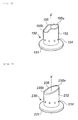
Fig. 4] Fig. 4 is a perspective view of a multifunctional member according to another embodiment; - [
Fig. 5] Fig. 5 is a perspective view of a multifunctional member according to still another embodiment; and - [
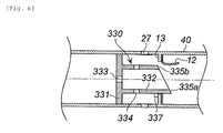
Fig. 6] Fig. 6 is a partial cross-sectional view illustrating an activated state of a multifunctional member according to still another embodiment. - In the gas generator disclosed in
US-A No. 2006/037662 , activation of theinitiator 20 causes theprojectile 22 to move and rupture the closure member 14, whereby the pressurized gas is discharged to the outside from a gas outlet 18. However, since the gas is not discharged unless the closure member 14 is ruptured, the time elapsed from activation (activation of the igniter 20) until the gas is discharged may become prolonged. In this regard, there is still room for further improvement. - In the gas generator disclosed in
US-B No. 7192052 , there is a possibility that, when the needle 94 passes through the burst disc 84, portions of the burst disc 84 through which the needle 94 passes may become fragments, and the fragments may flow outside the bottle 14 with the flow of the gas. - The present invention provides a gas generator capable of maintaining high performance during the service life of a vehicle and discharging gas in an earlier initial stage of activation without producing fragments of a closing member when applied to a restraining device of an airbag system of a vehicle or the like.
- The multifunctional member used in the gas generator according to the present invention functions to rupture the closing member, to hold the gas generating agent, and to secure the gas discharge path.
- The multifunctional member has the base plate portion and the cylindrical wall portion extended from one surface of the base plate portion. Moreover, an end of the cylindrical wall portion on an opposite side of the base plate portion is an opening portion having an inclined end surface.
- The presence of the multifunctional member enables to exhibit functions (I) and (II) below, and additionally a function (III).
- Before activation (before activation of an ignition device; the same applies hereinafter), the pressurized gas chamber housing is filled with a pressurized gas under high pressure.
- During activation, the multifunctional member (the base plate portion and the cylindrical wall portion having the inclined end surface) is moved in the axial direction (toward the closing member), whereby the closing member is ruptured by the inclined end surface of the opening portion of the cylindrical wall portion and the flow path for the pressurized gas is opened.
- Since the cylindrical wall portion has the inclined end surface on the opening portion thereof, the cylindrical wall portion has a longest portion and a shortest portion. Although the longest portion of the inclined end surface has a sharp tip end, the shortest portion does not have a sharp tip end. During activation, the closing member is ruptured by the tip end of the longest portion.
- In the gas generator of the present invention, the moving distance in the axial direction of the multifunctional member before and after activation is restricted by the movement restriction means such that the longest portion of the cylindrical wall portion passes through the closing member, but the shortest portion of the cylindrical wall portion does not pass through the closing member.
- Due to this, when the multifunctional member is moved so that the longest portion (the portion having the sharp tip end) of the inclined end surface collides with and passes through the closing member, the closing member is ruptured. However, since the shortest portion of the inclined end surface does not pass through the closing member, a portion of the closing member remains in a non-ruptured state.
- Thus, since the non-ruptured portion remains fixed to the closing member, the portions of the closing member ruptured by the sharp tip end remain in a state of being turned up toward the pressurized gas chamber housing.
- Due to this, there is no possibility that small fragments of the closing member scatter or the entire closing member is displaced to block the gas discharge path.
- The form of the closing member is not particularly limited as long as the closing member closes the space between the ignition device chamber housing and the pressurized gas chamber housing.
- The closing member can be a disc member (for example, a
rupture plate 40 inFig. 3 ofJP-A No. 2003-226222 - The disc member serving as the closing member is deformed in a bowl-like shape that protrudes toward the ignition device chamber housing by receiving pressure from the inside of the pressurized gas chamber housing. In this case, the multifunctional member is disposed so that the inclined end surface does not make contact with the closing member.
- The closing member can be also a bottom plate member (for example, a
rupture plate 10 inFig. 4 ofJP-A No. 2010-018132 - The movement restriction means may be configured such that one or both of the base plate portion and the cylindrical wall portion of the multifunctional member makes contact with another member to stop movement of the multifunctional member. For example, a protrusion may be formed on the base plate portion, the cylindrical wall portion and the ignition device chamber housing so that these protrusions make contact with each other to suppress movement of the multifunctional member.
- The base plate portion abuts against the inner wall surface of the ignition device chamber housing, and the cylindrical wall portion has an outer diameter smaller than an outer diameter of the base plate portion.
- By disposing such a multifunctional member in the ignition device chamber housing, the plenum chamber is formed. The cylindrical wall portion of the multifunctional member is positioned in the plenum chamber.
- The plenum chamber communicates with the gas generating agent charging chamber that is charged with the gas generating agent.
- During activation, a discharge path of the combustion gas generated in the gas generating agent charging chamber and a discharge path of the pressurized gas are secured. The gas generating agent charging chamber and the plenum chamber may communicate with each other before activation.
- The size of the communicating portion that makes communication between the gas generating agent charging chamber and the plenum chamber is set to such an opening area that the combustion gas generates a differential or a gradient in pressure between the gas generating agent charging chamber and the plenum chamber.
- Since the combustion gas is immediately discharged to the outside of the housing through the plenum chamber, an airbag can be inflated in a reliable and quick manner. At the same time, the multifunctional member is moved by pressure by the combustion gas to rupture the closing member.
- In the present invention, since the opening portion of the cylindrical wall portion of the multifunctional member has the inclined end surface, the gas may flow directly into the plenum chamber through the gap between the shortest portion and the portion of the closing member turned up toward the pressurized gas chamber housing to be discharged from the gas discharge port.
- The function to hold the gas generating agent may be obtained by the multifunctional member used in the gas generator according to the present invention or may be obtained by another member. The function to hold the gas generating agent may be exhibited by the multifunctional member as follows:
- Before activation, one surface of the gas generating agent charging chamber is formed by the base plate portion of the multifunctional member and the charged gas generating agent is supported and fixed.
- When the gas generator is mounted on a vehicle, vibration is applied to the gas generator over a long period of time. If the gas generating agent is insufficiently fixed, the gas generating agents may rub against each other and become pulverized.
- When the gas generating agent is pulverized in this manner, a designed combustion state is not obtained and the performance of the gas generator is also affected.
- In the present invention, when the gas generating agent is directly or indirectly supported and fixed by the multifunctional member, pulverization of the gas generating agent is prevented by the multifunctional member.
- In order to exhibit the functions (I) and (II), or in order that the annular end surface of the opening portion of the cylindrical wall portion (32) of the multifunctional member(30) is the inclined end surface(35) that is inclined with respect to the base plate portion (31), the multifunctional member used in the gas generator of the present invention is preferably configured as follows:
- the ratio between a smallest length (Lmin) to a largest length (Lmax) of the cylindrical wall portion is preferably in a range of 20% and 75%, and more preferably, in a range of 30% and 60%;
- part of the inclined end surface is depressed toward the base plate portion; or
- the inclined end surface has a wavy convex and concave surface.
- In order to exhibit the functions (I) and (II), the gas generator of the present invention preferably includes at least one of the followings as the movement restriction means for the multifunctional member.
- (1) The inner wall surface of the ignition device chamber housing has a first protrusion and a second protrusion formed at an interval in the axial direction so as to protrude inward,
before activation, the multifunctional member is disposed in the ignition device chamber housing so that the base plate portion abuts against the first protrusion,
during activation, movement of the base plate portion is restricted within a moving distance from the first protrusion to the second protrusion, - Movement of the multifunctional member is restricted within the range of the first protrusion and the second protrusion, and the closing member is ruptured by the multifunctional member that has moved within this restricted range.
- (2) The closing member that closes a boundary surface between the ignition device chamber housing and the pressurized gas chamber housing has or is attached to an annular plate portion that is integrated with an inner wall surface of either the ignition device chamber housing or the pressurized gas chamber housing,
the cylindrical wall portion has an inclined end surface on the opening portion, inclined with respect to the base plate portion,
a protrusion is formed on an outer wall surface of the longest portion of the cylindrical wall portion so as to protrude outward, and
the protrusion collides with an annular plate portion that protrudes inward from an inner wall surface of either the ignition device chamber housing or the pressurized gas chamber housing, so that movement of the multifunctional member in the axial direction is restricted. - (3) The closing member that closes a boundary surface between the ignition device chamber housing and the pressurized gas chamber housing is integrated with an inner wall surface of either the ignition device chamber housing or the pressurized gas chamber housing, a central portion of the closing member is ruptured and opened during activation, and an annular portion around the central portion remains in a state of being integrated with either the ignition device chamber housing or the pressurized gas chamber housing,
the cylindrical wall portion has an inclined end surface on the opening portion, inclined with respect to the base plate portion,
a protrusion is formed so as to protrude outward from an outer wall surface of the longest portion of the cylindrical wall portion, and
the protrusion collides with the remaining annular portion, so that movement of the multifunctional member in the axial direction is restricted. - By using a novel multifunctional member as a constituent component, the gas generator according to present invention maintains high performance during a service life of a vehicle when applied to a restraining device of an airbag system of the vehicle or the like.
- A
gas generator 10 includes an ignitiondevice chamber housing 20 and a pressurizedgas chamber housing 40 which are joined to form an outer-shell container. - A closing
member 12 closes between the ignitiondevice chamber housing 20 and the pressurizedgas chamber housing 40. - A circumference edge of the closing
member 12 is welded and fixed, from the pressurizedgas chamber housing 40, to anannular plate portion 13 that protrudes inward from an inner wall surface of the ignitiondevice chamber housing 20. Theannular plate portion 13 may be one that protrudes inward from the inner wall surface of the pressurizedgas chamber housing 40. - The closing
member 12 may be one that is integrated with one of the ignitiondevice chamber housing 20 and the pressurized gas chamber housing 40 (for example, a bottom plate member of any one of the housings). - The closing
member 12 has a disc shape (a flat-plate shape) before assembling, and is deformed in a bowl-like shape in response to pressure of a pressurized gas inside the pressurizedgas chamber housing 40. - An opening portion (the opening portion opposite to the closing member 12) of the ignition
device chamber housing 20 is closed by anelectric igniter 25 fixed thereto. - The
electric igniter 25 fixed to a collar is fixed by being held from both sides in the X-axis direction by an inwardannular protrusion 21a formed on ancircumferential wall portion 21 of the ignitiondevice chamber housing 20 and an openingend portion 22 crimped inward. - A
multifunctional member 30 having the functions (I) to (III) described above is arranged in the ignitiondevice chamber housing 20. - The
multifunctional member 30 has abase plate portion 31 and acylindrical wall portion 32 extended from one surface of thebase plate portion 31. - The
base plate portion 31 is movable and in contact with the inner wall surface (a circumferential wall portion) 21 of the ignitiondevice chamber housing 20, and has a first through-hole 33 in a thickness direction thereof. The first through-hole 33 may be closed by an aluminum adhesive tape or the like that is readily broken. - In
Fig. 1 , the first through-holes 33 are formed at the center of thebase plate portion 31 to enable communication with the inner space (a plenum chamber 36) of thecylindrical wall portion 32. However, the first through-holes 33 may be formed near the peripheral edge of thebase plate portion 31 to enable communication with theplenum chamber 36. - The number of the first through-
hole 33 is not particularly limited. Moreover, a recess may be formed in the peripheral edge of thebase plate portion 31 to form a gap between the recess and theinner wall surface 21 of the ignitiondevice chamber housing 20, so that the gap serves as the first through-hole. - The
cylindrical wall portion 32 has the same central axis X as thebase plate portion 31, and an outer diameter of thecylindrical wall portion 32 is smaller than an outer diameter of thebase plate portion 31. - The
cylindrical wall portion 32 has a plurality of second through-holes 34 in the thickness direction thereof. - An annular end surface (an end surface close to the closing member 12) of the opening portion of the
cylindrical wall portion 32 is configured as aninclined end surface 35 that is inclined with respect to thebase plate portion 31. - The
cylindrical wall portion 32 having theinclined end surface 35 has thelongest portion 35a and theshortest portion 35b, and a tip end portion including thelongest portion 35a has a sharp edge. - The length between the tip of the
longest portion 35a and thebase plate portion 31 is a largest length (Lmax). The length between the tip of theshortest portion 35b and thebase plate portion 31 is a smallest length (Lmin). - The ratio, Lmin/Lmax, of the length (Lmin) of the
shortest portion 35b to the length (Lmax) of thelongest portion 35a of thecylindrical wall portion 32 is between 20% and 75%. - In
Fig. 2 , although theinclined end surface 35 is a continuous inclined end surface (the cross-section of the end surface is an inclined straight line), a portion (one or multiple portions) between thelongest portion 35a and theshortest portion 35b may be depressed toward thebase plate portion 31. - The inclined end surface 35 (the
longest portion 35a) of thecylindrical wall portion 32 is not in contact with the closingmember 12 before activation. - A protrusion (a first protrusion) 21b is formed on the
inner wall surface 21 of the ignitiondevice chamber housing 20. Before activation, thebase plate portion 31 of themultifunctional member 30 abuts against the protrusion (the first protrusion) 21b to prevent movement toward theigniter 25. - Although not illustrated in the drawings, the
multifunctional member 30 is temporarily clamped by a temporary fixing means, so that themultifunctional member 30 does not move toward the closingmember 12 before activation (that is, themultifunctional member 30 does not move in response to vibration from a vehicle to which the gas generator is attached) and that themultifunctional member 30 ruptures the closingmember 12 by moving toward the closingmember 12 in response to the pressure of the combustion gas during activation. - An example of the temporary fixing means can be a protrusion which holds the
base plate portion 31 together with the protrusion (the first protrusion) 21b in the thickness direction, in which the inwardly protruding length of the protrusion is smaller than the protrusion (the first protrusion) 21b and the width of the protrusion is smaller than theprotrusion 21b. - In addition to this, a shallow and narrow annular groove may be formed on the circumferential surface of the
base plate portion 31, and a protrusion corresponding to the annular groove on the circumferential surface may be formed on theinner wall surface 21 so that a combination of the annular groove and the protrusion provides the temporary fixing function. - In a portion of the
inner wall surface 21 of the ignition device chamber housing, a step (a second protrusion) 26 is arranged between thefirst protrusion 21b and the closingmember 12. - A combination of the
first protrusion 21b and the step (the second protrusion) 26 forms a movement restriction means that restricts a moving distance (a moving range) of themultifunctional member 30 in the X-axis direction. - The moving distance (r1 in (a) in
Fig. 3 ) restricted by the combination of the protrusion (the first protrusion) 21b and the step (the second protrusion) 26 is set to such a distance that thelongest portion 35a of thecylindrical wall portion 32 passes through the closingmember 12, preferably, passes through aboundary surface 50 between the closingmember 12 and the annular plate portion 13 (to move a distance of r2 or more) and that theshortest portion 35b of thecylindrical wall portion 32 does not pass through the boundary surface 50 (to move a distance equal to r3 or smaller). - Here, the
boundary surface 50 is an imaginary surface that passes through the boundary between the closingmember 12 and theannular plate portion 13. - Here, r1, r2, and r3 satisfy a relation of r1>r2 and r1<r3, and can be adjusted appropriately within such a range that the relation is satisfied.
- For example, r1/r2 may be set between 1.3 and 4, and r3/r1 may be set between 1.3 and 4.
- A plurality of
gas discharge ports 27 are formed, between thestep 26 and the closingmember 12, in theinner wall surface 21 of the ignitiondevice chamber housing 20. For moisture-proofing, the plurality ofgas discharge ports 27 are closed from the inside by an aluminum adhesive tape or the like. - In the ignition
device chamber housing 20, the space enclosed by thebase plate portion 31, theinner wall surface 21 and the closingmember 12 is theplenum chamber 36 that forms the gas discharge path. Since thecylindrical wall portion 32 is positioned inside theplenum chamber 36, both the inside and the outside of thecylindrical wall portion 32 are theplenum chamber 36. Thegas discharge port 27 faces theplenum chamber 36. - The space enclosed by the
base plate portion 31, theigniter 25 and theinner wall surface 21 is a gas generatingagent charging chamber 37, and a molded article of knowngas generating agent 38 is charged in the gas generatingagent charging chamber 37. - An amount of the molded article of the
gas generating agent 38 used is determined appropriately according to the type of the gas generator. - The pressurized
gas chamber housing 40 is filled with a gas such as argon or helium under high pressure. - The gas is filled from a gap between a pore and a
pin 42 inserted into the pore on abottom surface 41. After the gas is filled, the pore is closed by welding thebottom surface 41 and thepin 42. - Operations of the gas generator (a hybrid-type gas generator) illustrated in
Fig. 1 used in a restraining device of an airbag system for a vehicle will be described below. - When the
igniter 25 is activated, the molded article ofgas generating agent 38 in the gas generatingagent charging chamber 37 is ignited and combusted to generate combustion gas. - The generated combustion gas immediately enters the
plenum chamber 36 inside thecylindrical wall portion 32 through the first through-hole 33 and enters theplenum chamber 36 outside thecylindrical wall portion 32 through the second through-hole 34 to break the moisture-proofing seal tape. After that, the gas is discharged from thegas discharge port 27 to inflate an airbag. - Therefore, the gas can be quickly discharged with the activation of the gas generator and the activation (deployment) of a restraining device such as an airbag can be quickly started.
- On the other hand, when the pressure in the gas generating
agent charging chamber 37 rises due to the generation of the combustion gas, thebase plate portion 31 of themultifunctional member 30 is pushed in the X-axis direction and thecylindrical wall portion 32 having theinclined end surface 35 is moved in the X-axis direction. - In this case, as illustrated in (a) and (b) in
Fig. 3 , thebase plate portion 31 stops after moving from the protrusion (the first protrusion) 21b to the step (the second protrusion) 26. As a result, thelongest portion 35a having a sharp edge passes through theboundary surface 50, whereby the closingmember 12 is ruptured and opened from the annular plate portion 13 (r1>r2 in (a) inFig. 3 , and the inner diameter of theannular plate portion 13 is slightly larger than the outer diameter of the cylindrical wall portion 32). - In this case, although the
shortest portion 35b also collides with the closingmember 12, theshortest portion 35b does not pass through the boundary surface 50 (r1<r3 in (a) inFig. 3 ), preferably, does not pass through the closingmember 12, theshortest portion 35b does not have a sharp edge, and therefore, the closingmember 12 that theshortest portion 35b faces is not ruptured. - When the
multifunctional member 30 collides with the closingmember 12 and the pressure inside theplenum chamber 36 has increased, the closingmember 12 is ruptured to be turned up toward the pressurizedgas chamber housing 40 as illustrated in (b) inFig. 3 . After that, since the gas inside the pressurizedgas chamber housing 40 is discharged and the pressure decreases, the closingmember 12 maintains this state. - The moving distance (r3) of the
shortest portion 35b may be adjusted so that theshortest portion 35b abuts against the opened and turned-up closingmember 12, or the moving distance (r3) may be adjusted so that a gap serving as the gas discharge path is formed between theshortest portion 35b and the opened and turned-up closingmember 12. - Moreover, when part (one or multiple portions) of the
inclined end surface 35 of thecylindrical wall portion 32 is depressed toward thebase plate portion 31, even if the moving distance (r3) is adjusted so that theshortest portion 35b abuts against the opened and turned-up closingmember 12, the depression functions as the gas discharge path together with the second through-hole 34. - The gas inside the pressurized
gas chamber housing 40 passes through an opening formed by the ruptured closingmember 12, the second through-hole 34 and theplenum chamber 36 outside thecylindrical wall portion 32, and is discharged from thegas discharge port 27 to inflate an airbag. - The gas inside the pressurized
gas chamber housing 40 can directly enter theplenum chamber 36 outside thecylindrical wall portion 32 and be discharged form thegas discharge port 27 to inflate the airbag. -
Fig. 4 is a perspective view of amultifunctional member 130 used in a gas generator. Themultifunctional member 130 has the same functions and operations as themultifunctional member 30 inFig. 1 except that themultifunctional member 30 has a shape different from theinclined end surface 135. - The
multifunctional member 130 has abase plate portion 131 and acylindrical wall portion 132 extended from one surface of thebase plate portion 131. - The
base plate portion 131 has a first through-hole similarly to thebase plate portion 31 ofFig. 1 . - The
cylindrical wall portion 132 has aninclined end surface 135 that has a wavy convex and concave surface, and has alongest portion 135a and ashortest portion 135b. A convex portion is formed between thelongest portion 135a and theshortest portion 135b. - A concave portion of the
inclined end surface 135 functions, together with the second through-hole 134, as a gas discharge path along which the gas is discharged from the pressurizedgas chamber housing 40. -
Fig. 5 is a perspective view of amultifunctional member 230 used in a gas generator. - The
multifunctional member 230 has abase plate portion 231 and acylindrical wall portion 232 extended from one surface of thebase plate portion 231. - The
base plate portion 231 has a first through-hole similarly to thebase plate portion 31 inFig. 1 . - The
cylindrical wall portion 232 has an opening end surface that is configured as aninclined end surface 235 and has alongest portion 235a and ashortest portion 235b. - In the
cylindrical wall portion 232, thelongest portion 235a has a smallest thickness and theshortest portion 235b has a largest thickness (Tmax). - A tip end of the
longest portion 235a having the smallest thickness has a sharp edge and functions to rupture the closingmember 12 when themultifunctional member 230 is moved in the X-axis direction during activation. - The
shortest portion 235b having the largest thickness collides with the closingmember 12 to restrict further movement of themultifunctional member 230 when themultifunctional member 230 is moved in the X-axis direction during activation. - Due to this, when the
multifunctional member 230 shown inFig. 5 is used in the gas generator inFig. 1 , thestep 26 that restricts the movement of themultifunctional member 230 may not be needed. -
Fig. 6 is a cross-sectional view in the axial direction of amultifunctional member 330 used in a gas generator. - The
multifunctional member 330 has abase plate portion 331 and acylindrical wall portion 332 extended from one surface of thebase plate portion 331. - The
base plate portion 331 has a first through-hole similarly to thebase plate portion 31 inFig. 1 . - The
cylindrical wall portion 332 has an opening end surface that is configured as an inclined end surface 335 and has alongest portion 335a and ashortest portion 335b. - A
protrusion 337 protruding outward is formed on an outer wall surface of thelongest portion 335a of thecylindrical wall portion 332. - The
protrusion 337 collides with theannular plate portion 13 to which the closingmember 12 is welded and fixed so as to restrict further movement of themultifunctional member 330 when themultifunctional member 330 is moved in the X-axis direction during activation. - Due to this, when the
multifunctional member 330 shown inFig. 6 is used in the gas generator inFig. 1 , thestep 26 that restricts the movement of themultifunctional member 330 may not be needed. - A specific embodiment of the gas generator according to the present invention is not limited to the present embodiments as long as the problem described above can be solved. For example, different embodiments can be adopted with respect to the shape of the multifunctional member, the annular protrusion and the step formed on the ignition device chamber housing, and the like in order to realize similar functions.
- The invention thus described, it will be obvious that the same may be varied in many ways. Such variations are not to be regarded as a departure from the spirit and scope of the invention, and all such modifications as would be obvious to one skilled in the art are intended to be included within the scope of the following claims.
the first protrusion is an inward protrusion formed in a circumferential wall portion of the ignition device chamber housing so as to be recessed from the outside, and the second protrusion is a step formed on the circumferential wall portion of the ignition device chamber housing facing the plenum chamber.
Claims (8)
- A gas generator (10), comprising
a cylindrical ignition device chamber housing (20) provided with a gas discharge port (27), accommodating an igniter(25) and a gas generating agent(38), a cylindrical pressurized gas chamber housing (40) filled with pressurized gas, the ignition device chamber housing (20) joining to the pressurized gas chamber housing (40) to form an outer container,
a closing member(12) closing between the ignition device chamber housing (20) and the pressurized gas chamber housing (40),
a multifunctional member(30), movable in the axial direction during activation, being disposed inside the ignition device chamber housing (20) together with the igniter(25) and the gas generating agent(38),
the igniter(25) closing the opening portion of the ignition device chamber housing (20) and being fixed thereto,
the multifunctional member(30) having a base plate portion (31) and a cylindrical wall portion (32) extending from one surface of the base plate portion (31), an annular end surface of the opening portion of the cylindrical wall portion (32) including an inclined end surface(35) inclined with respect to the base plate portion (31), the inclined end surface(35) being arranged not in contact with the closing member(12),
a plenum chamber(36), being enclosed by the ignition device chamber housing (20), the base plate portion (31) and the closing member(12),
the gas discharge port (27) formed in a circumferential wall portion, of the ignition device chamber housing (20), to face the plenum chamber(36),
a gas generating agent charging chamber(37), charged with a gas generating agent(38), enclosed by the base plate portion (31), the igniter(25) and an inner wall surface(21) of the ignition device chamber housing, the plenum chamber(36) and the gas generating agent charging chamber(37) communicating with each other,
the multifunctional member(30) moving in the axial direction by internal pressure increase due to combustion gas generated by combustion of the gas generating agent(38) in the gas generating agent charging chamber(37) to break the closing member(12) with the inclined end surface(35) of the cylindrical wall portion (32), and thereby, obtaining a gas discharge path, and
a movement restriction means restricting a moving distance in the axial direction of the multifunctional member(30) before and after activation such that a longest portion of the cylindrical wall portion (32) passes through the closing member(12) but a shortest portion of the cylindrical wall portion (32) does not pass through the closing member(12). - The gas generator (10) according to claim 1, wherein
the annular end surface of the opening portion of the cylindrical wall portion (32) of the multifunctional member(30) is the inclined end surface(35) that is inclined with respect to the base plate portion (31), and
the ratio between a smallest length (Lmin) to a largest length (Lmax) of the cylindrical wall portion (32) is in a range of 20% and 75%. - The gas generator (10) according to claim 1 or 2, wherein
the annular end surface of the opening portion of the cylindrical wall portion (32) of the multifunctional member(30) is the inclined end surface(35) that is inclined with respect to the base plate portion (31), and
part of the inclined end surface(35) is depressed toward the base plate portion (31). - The gas generator (10) according to claim 1 or 2, wherein
the annular end surface of the opening portion of the cylindrical wall portion (32) of the multifunctional member(30) is an inclined end surface(35) that is inclined with respect to the base plate portion (31), and
the inclined end surface (35) has a wavy convex and concave surface. - The gas generator according to any one of claims 1 to 4, wherein
the inner wall surface of the ignition device chamber housing (20) has a first protrusion (21b) and a second protrusion (26) formed at an interval in the axial direction so as to protrude inward,
before activation, the multifunctional member(30) is disposed in the ignition device chamber housing (20) so that the base plate portion (31) abuts against the first protrusion (21b),
during activation, movement of the base plate portion (31) is restricted within a moving distance from the first protrusion (21b) to the second protrusion (26). - The gas generator according to claim 5, wherein the first protrusion (21b) is an inward protrusion formed in a circumferential wall portion of the ignition device chamber housing (20) so as to be recessed from the outside, and
the second protrusion (26) is a step formed on the circumferential wall portion of the ignition device chamber housing (20) facing the plenum chamber(36). - The gas generator according to any one of claims 1 to 4, wherein
the closing member(12) that closes between the ignition device chamber housing (20) and the pressurized gas chamber housing (40) has or is attached to an annular plate portion (13) that is integrated with an inner wall surface of either the ignition device chamber housing (20) or the pressurized gas chamber housing (40),
the cylindrical wall portion (32) has an inclined end surface(35) on the opening portion, inclined with respect to the base plate portion (31),
a protrusion is formed on an outer wall surface of the longest portion of the cylindrical wall portion (32) so as to protrude outward, and
the protrusion collides with an annular plate portion (13) that protrudes inward from an inner wall surface of either the ignition device chamber housing (20) or the pressurized gas chamber housing (40), so that movement of the multifunctional member(30) in the axial direction is restricted. - The gas generator according to any one of claims 1 to 4, wherein
the closing member(12) that closes between the ignition device chamber housing (20) and the pressurized gas chamber housing (40) is integrated with an inner wall surface of either the ignition device chamber housing (20) or the pressurized gas chamber housing (40), a central portion of the closing member is ruptured and opened during activation, and an annular portion around the central portion remains in a state of being integrated with either the ignition device chamber housing (20) or the pressurized gas chamber housing (40),
the cylindrical wall portion (32) has an inclined end surface(35) on the opening portion, inclined with respect to the base plate portion (31),
a protrusion is formed so as to protrude outward from an outer wall surface of the longest portion of the cylindrical wall portion (32), and
the protrusion collides with the remaining annular portion, so that movement of the multifunctional member(30) in the axial direction is restricted.
Applications Claiming Priority (2)
| Application Number | Priority Date | Filing Date | Title |
|---|---|---|---|
| JP2013015406A JP6154147B2 (en) | 2013-01-30 | 2013-01-30 | Gas generator |
| PCT/JP2014/050488 WO2014119361A1 (en) | 2013-01-30 | 2014-01-15 | Gas generator |
Publications (3)
| Publication Number | Publication Date |
|---|---|
| EP2952394A1 true EP2952394A1 (en) | 2015-12-09 |
| EP2952394A4 EP2952394A4 (en) | 2016-08-24 |
| EP2952394B1 EP2952394B1 (en) | 2017-08-02 |
Family
ID=51221534
Family Applications (1)
| Application Number | Title | Priority Date | Filing Date |
|---|---|---|---|
| EP14745469.8A Active EP2952394B1 (en) | 2013-01-30 | 2014-01-15 | Gas generator |
Country Status (6)
| Country | Link |
|---|---|
| US (1) | US8870222B2 (en) |
| EP (1) | EP2952394B1 (en) |
| JP (1) | JP6154147B2 (en) |
| KR (1) | KR20150111914A (en) |
| CN (1) | CN104936832B (en) |
| WO (1) | WO2014119361A1 (en) |
Cited By (1)
| Publication number | Priority date | Publication date | Assignee | Title |
|---|---|---|---|---|
| US10336289B2 (en) * | 2016-02-12 | 2019-07-02 | Trw Airbag Systems Gmbh | Hybrid inflator, method of operating a hybrid inflator, airbag module and vehicle safety system |
Families Citing this family (17)
| Publication number | Priority date | Publication date | Assignee | Title |
|---|---|---|---|---|
| JP6095463B2 (en) * | 2013-04-22 | 2017-03-15 | 株式会社ダイセル | Gas generator |
| JP2015205661A (en) * | 2014-04-23 | 2015-11-19 | 株式会社ダイセル | Gas producer |
| JP6284420B2 (en) * | 2014-04-23 | 2018-02-28 | 株式会社ダイセル | Inflator |
| JP6312545B2 (en) * | 2014-07-24 | 2018-04-18 | 日本化薬株式会社 | Gas generator |
| JP6312571B2 (en) * | 2014-09-29 | 2018-04-18 | 株式会社ダイセル | Gas generator |
| JP6251662B2 (en) * | 2014-09-29 | 2017-12-20 | 株式会社ダイセル | Gas generator |
| GB201707283D0 (en) * | 2014-11-09 | 2017-06-21 | Hip Hope Tech Ltd | Air bag mechanism |
| CN107531209A (en) | 2015-05-22 | 2018-01-02 | 株式会社大赛璐 | Gas generator |
| JP2016222117A (en) * | 2015-05-29 | 2016-12-28 | 株式会社ダイセル | Gas generator |
| US9863442B2 (en) * | 2015-07-17 | 2018-01-09 | Goodrich Corporation | Collapsible/extendable aspirator system |
| JP6504963B2 (en) | 2015-08-05 | 2019-04-24 | 株式会社ダイセル | Closed structure of cylindrical housing opening and gas generator |
| JP6514067B2 (en) | 2015-08-19 | 2019-05-15 | 株式会社ダイセル | Rolling crimping tool and method of closing cylindrical member opening using the same |
| JP6543560B2 (en) * | 2015-11-26 | 2019-07-10 | 株式会社ダイセル | Gas generator |
| JP6813997B2 (en) * | 2016-09-02 | 2021-01-13 | 株式会社ダイセル | Small aircraft with airbag device |
| JP6876539B2 (en) * | 2017-06-20 | 2021-05-26 | 株式会社ダイセル | Pressure-resistant container |
| JP6880505B2 (en) * | 2017-07-14 | 2021-06-02 | 株式会社ダイセル | Discharger and gas generator |
| US12595991B2 (en) * | 2021-11-30 | 2026-04-07 | Daicel Corporation | Gas generator |
Family Cites Families (15)
| Publication number | Priority date | Publication date | Assignee | Title |
|---|---|---|---|---|
| DE19638838A1 (en) * | 1996-09-21 | 1998-03-26 | Dynamit Nobel Ag | Hybrid gas generator for an airbag with a mechanical opening mechanism for the storage chamber |
| US6010153A (en) * | 1997-02-21 | 2000-01-04 | Breed Automotive Technology, Inc. | Hybrid inflator for airbags |
| JPH10278724A (en) * | 1997-04-11 | 1998-10-20 | Matsushita Electric Ind Co Ltd | Gas generating method and device for airbag device |
| US6499764B2 (en) * | 1997-06-17 | 2002-12-31 | Dynamit Nobel Gmbh Explosivstoff-Und Systemtechnik | Gas generator |
| DE19725476A1 (en) * | 1997-06-17 | 1998-12-24 | Dynamit Nobel Ag | Gas generator |
| JP3060295U (en) * | 1998-12-09 | 1999-08-17 | 二三生 古川 | Emergency gas ejection device and human body airbag device |
| US6543806B1 (en) * | 2000-08-03 | 2003-04-08 | Nxgen Technologies Llc | Inflator for vehicle protection apparatus |
| US7159622B1 (en) | 2000-08-03 | 2007-01-09 | Delphi Technologies, Inc. | Inflator for vehicle protection apparatus |
| US7134689B2 (en) | 2001-11-30 | 2006-11-14 | Daicel Chemical Industries, Ltd. | Inflator |
| JP2003226222A (en) | 2001-11-30 | 2003-08-12 | Daicel Chem Ind Ltd | Inflator |
| US7192052B2 (en) | 2003-09-24 | 2007-03-20 | Autoliv Asp, Inc. | Inflation assembly with extended filling capability |
| FR2876968B1 (en) * | 2004-10-26 | 2007-01-12 | Livbag Soc Par Actions Simplif | GAS GENERATOR EQUIPPED WITH PRESSURE CONTROL MEANS AND SAFETY DEVICE PROVIDED THEREIN. |
| FR2894658B1 (en) * | 2005-12-13 | 2010-11-12 | Livbag | HYBRID TYPE GAS GENERATOR, COMPRISING A METAL LOAD. |
| JP5242268B2 (en) | 2008-07-10 | 2013-07-24 | 株式会社ダイセル | Inflator assembly method |
| CN201506324U (en) * | 2009-06-26 | 2010-06-16 | 比亚迪股份有限公司 | Hybrid Gas Generator |
-
2013
- 2013-01-30 JP JP2013015406A patent/JP6154147B2/en active Active
-
2014
- 2014-01-15 EP EP14745469.8A patent/EP2952394B1/en active Active
- 2014-01-15 KR KR1020157019395A patent/KR20150111914A/en not_active Withdrawn
- 2014-01-15 CN CN201480005941.2A patent/CN104936832B/en active Active
- 2014-01-15 WO PCT/JP2014/050488 patent/WO2014119361A1/en not_active Ceased
- 2014-01-29 US US14/167,701 patent/US8870222B2/en active Active
Cited By (1)
| Publication number | Priority date | Publication date | Assignee | Title |
|---|---|---|---|---|
| US10336289B2 (en) * | 2016-02-12 | 2019-07-02 | Trw Airbag Systems Gmbh | Hybrid inflator, method of operating a hybrid inflator, airbag module and vehicle safety system |
Also Published As
| Publication number | Publication date |
|---|---|
| WO2014119361A1 (en) | 2014-08-07 |
| KR20150111914A (en) | 2015-10-06 |
| EP2952394B1 (en) | 2017-08-02 |
| US8870222B2 (en) | 2014-10-28 |
| CN104936832B (en) | 2017-05-10 |
| EP2952394A4 (en) | 2016-08-24 |
| JP6154147B2 (en) | 2017-06-28 |
| CN104936832A (en) | 2015-09-23 |
| US20140208975A1 (en) | 2014-07-31 |
| JP2014144736A (en) | 2014-08-14 |
Similar Documents
| Publication | Publication Date | Title |
|---|---|---|
| EP2952394B1 (en) | Gas generator | |
| CN104755328B (en) | Gas generator | |
| US7637535B2 (en) | Inflator for an air bag | |
| US10981534B2 (en) | Gas generator | |
| CN105339215A (en) | Gas generator for occupant restraining device | |
| CN1938180A (en) | Gas generator | |
| US11555613B2 (en) | Gas generator | |
| EP1927519B1 (en) | Inflator | |
| US20060249938A1 (en) | Gas generator for air bag | |
| JP2001347916A (en) | Inflator and air bag device | |
| EP2987685B1 (en) | Gas generator | |
| US20050189750A1 (en) | Hybrid inflator | |
| EP1375265B1 (en) | Gas generating apparatus for air bag apparatus | |
| JP4576282B2 (en) | Gas generator for airbag | |
| EP1559621A2 (en) | Hybrid inflator | |
| JP2024046153A (en) | Gas generator | |
| EP1604873A2 (en) | Inflator for an airbag | |
| JP2009179100A (en) | Gas generator |
Legal Events
| Date | Code | Title | Description |
|---|---|---|---|
| PUAI | Public reference made under article 153(3) epc to a published international application that has entered the european phase |
Free format text: ORIGINAL CODE: 0009012 |
|
| 17P | Request for examination filed |
Effective date: 20150723 |
|
| AK | Designated contracting states |
Kind code of ref document: A1 Designated state(s): AL AT BE BG CH CY CZ DE DK EE ES FI FR GB GR HR HU IE IS IT LI LT LU LV MC MK MT NL NO PL PT RO RS SE SI SK SM TR |
|
| AX | Request for extension of the european patent |
Extension state: BA ME |
|
| RAP3 | Party data changed (applicant data changed or rights of an application transferred) |
Owner name: DAICEL CORPORATION |
|
| DAX | Request for extension of the european patent (deleted) | ||
| A4 | Supplementary search report drawn up and despatched |
Effective date: 20160721 |
|
| RIC1 | Information provided on ipc code assigned before grant |
Ipc: B60R 21/272 20060101AFI20160715BHEP Ipc: B01J 7/00 20060101ALI20160715BHEP |
|
| GRAP | Despatch of communication of intention to grant a patent |
Free format text: ORIGINAL CODE: EPIDOSNIGR1 |
|
| INTG | Intention to grant announced |
Effective date: 20170224 |
|
| GRAS | Grant fee paid |
Free format text: ORIGINAL CODE: EPIDOSNIGR3 |
|
| GRAA | (expected) grant |
Free format text: ORIGINAL CODE: 0009210 |
|
| AK | Designated contracting states |
Kind code of ref document: B1 Designated state(s): AL AT BE BG CH CY CZ DE DK EE ES FI FR GB GR HR HU IE IS IT LI LT LU LV MC MK MT NL NO PL PT RO RS SE SI SK SM TR |
|
| REG | Reference to a national code |
Ref country code: CH Ref legal event code: EP Ref country code: AT Ref legal event code: REF Ref document number: 914074 Country of ref document: AT Kind code of ref document: T Effective date: 20170815 |
|
| REG | Reference to a national code |
Ref country code: IE Ref legal event code: FG4D |
|
| REG | Reference to a national code |
Ref country code: DE Ref legal event code: R096 Ref document number: 602014012607 Country of ref document: DE |
|
| REG | Reference to a national code |
Ref country code: NL Ref legal event code: MP Effective date: 20170802 |
|
| REG | Reference to a national code |
Ref country code: AT Ref legal event code: MK05 Ref document number: 914074 Country of ref document: AT Kind code of ref document: T Effective date: 20170802 |
|
| REG | Reference to a national code |
Ref country code: LT Ref legal event code: MG4D |
|
| PG25 | Lapsed in a contracting state [announced via postgrant information from national office to epo] |
Ref country code: SE Free format text: LAPSE BECAUSE OF FAILURE TO SUBMIT A TRANSLATION OF THE DESCRIPTION OR TO PAY THE FEE WITHIN THE PRESCRIBED TIME-LIMIT Effective date: 20170802 Ref country code: AT Free format text: LAPSE BECAUSE OF FAILURE TO SUBMIT A TRANSLATION OF THE DESCRIPTION OR TO PAY THE FEE WITHIN THE PRESCRIBED TIME-LIMIT Effective date: 20170802 Ref country code: NL Free format text: LAPSE BECAUSE OF FAILURE TO SUBMIT A TRANSLATION OF THE DESCRIPTION OR TO PAY THE FEE WITHIN THE PRESCRIBED TIME-LIMIT Effective date: 20170802 Ref country code: LT Free format text: LAPSE BECAUSE OF FAILURE TO SUBMIT A TRANSLATION OF THE DESCRIPTION OR TO PAY THE FEE WITHIN THE PRESCRIBED TIME-LIMIT Effective date: 20170802 Ref country code: FI Free format text: LAPSE BECAUSE OF FAILURE TO SUBMIT A TRANSLATION OF THE DESCRIPTION OR TO PAY THE FEE WITHIN THE PRESCRIBED TIME-LIMIT Effective date: 20170802 Ref country code: HR Free format text: LAPSE BECAUSE OF FAILURE TO SUBMIT A TRANSLATION OF THE DESCRIPTION OR TO PAY THE FEE WITHIN THE PRESCRIBED TIME-LIMIT Effective date: 20170802 Ref country code: NO Free format text: LAPSE BECAUSE OF FAILURE TO SUBMIT A TRANSLATION OF THE DESCRIPTION OR TO PAY THE FEE WITHIN THE PRESCRIBED TIME-LIMIT Effective date: 20171102 |
|
| PG25 | Lapsed in a contracting state [announced via postgrant information from national office to epo] |
Ref country code: RS Free format text: LAPSE BECAUSE OF FAILURE TO SUBMIT A TRANSLATION OF THE DESCRIPTION OR TO PAY THE FEE WITHIN THE PRESCRIBED TIME-LIMIT Effective date: 20170802 Ref country code: LV Free format text: LAPSE BECAUSE OF FAILURE TO SUBMIT A TRANSLATION OF THE DESCRIPTION OR TO PAY THE FEE WITHIN THE PRESCRIBED TIME-LIMIT Effective date: 20170802 Ref country code: PL Free format text: LAPSE BECAUSE OF FAILURE TO SUBMIT A TRANSLATION OF THE DESCRIPTION OR TO PAY THE FEE WITHIN THE PRESCRIBED TIME-LIMIT Effective date: 20170802 Ref country code: BG Free format text: LAPSE BECAUSE OF FAILURE TO SUBMIT A TRANSLATION OF THE DESCRIPTION OR TO PAY THE FEE WITHIN THE PRESCRIBED TIME-LIMIT Effective date: 20171102 Ref country code: ES Free format text: LAPSE BECAUSE OF FAILURE TO SUBMIT A TRANSLATION OF THE DESCRIPTION OR TO PAY THE FEE WITHIN THE PRESCRIBED TIME-LIMIT Effective date: 20170802 Ref country code: GR Free format text: LAPSE BECAUSE OF FAILURE TO SUBMIT A TRANSLATION OF THE DESCRIPTION OR TO PAY THE FEE WITHIN THE PRESCRIBED TIME-LIMIT Effective date: 20171103 Ref country code: IS Free format text: LAPSE BECAUSE OF FAILURE TO SUBMIT A TRANSLATION OF THE DESCRIPTION OR TO PAY THE FEE WITHIN THE PRESCRIBED TIME-LIMIT Effective date: 20171202 |
|
| PG25 | Lapsed in a contracting state [announced via postgrant information from national office to epo] |
Ref country code: DK Free format text: LAPSE BECAUSE OF FAILURE TO SUBMIT A TRANSLATION OF THE DESCRIPTION OR TO PAY THE FEE WITHIN THE PRESCRIBED TIME-LIMIT Effective date: 20170802 Ref country code: RO Free format text: LAPSE BECAUSE OF FAILURE TO SUBMIT A TRANSLATION OF THE DESCRIPTION OR TO PAY THE FEE WITHIN THE PRESCRIBED TIME-LIMIT Effective date: 20170802 Ref country code: CZ Free format text: LAPSE BECAUSE OF FAILURE TO SUBMIT A TRANSLATION OF THE DESCRIPTION OR TO PAY THE FEE WITHIN THE PRESCRIBED TIME-LIMIT Effective date: 20170802 |
|
| REG | Reference to a national code |
Ref country code: DE Ref legal event code: R097 Ref document number: 602014012607 Country of ref document: DE |
|
| PG25 | Lapsed in a contracting state [announced via postgrant information from national office to epo] |
Ref country code: EE Free format text: LAPSE BECAUSE OF FAILURE TO SUBMIT A TRANSLATION OF THE DESCRIPTION OR TO PAY THE FEE WITHIN THE PRESCRIBED TIME-LIMIT Effective date: 20170802 Ref country code: SM Free format text: LAPSE BECAUSE OF FAILURE TO SUBMIT A TRANSLATION OF THE DESCRIPTION OR TO PAY THE FEE WITHIN THE PRESCRIBED TIME-LIMIT Effective date: 20170802 Ref country code: SK Free format text: LAPSE BECAUSE OF FAILURE TO SUBMIT A TRANSLATION OF THE DESCRIPTION OR TO PAY THE FEE WITHIN THE PRESCRIBED TIME-LIMIT Effective date: 20170802 Ref country code: IT Free format text: LAPSE BECAUSE OF FAILURE TO SUBMIT A TRANSLATION OF THE DESCRIPTION OR TO PAY THE FEE WITHIN THE PRESCRIBED TIME-LIMIT Effective date: 20170802 |
|
| PLBE | No opposition filed within time limit |
Free format text: ORIGINAL CODE: 0009261 |
|
| STAA | Information on the status of an ep patent application or granted ep patent |
Free format text: STATUS: NO OPPOSITION FILED WITHIN TIME LIMIT |
|
| 26N | No opposition filed |
Effective date: 20180503 |
|
| PG25 | Lapsed in a contracting state [announced via postgrant information from national office to epo] |
Ref country code: SI Free format text: LAPSE BECAUSE OF FAILURE TO SUBMIT A TRANSLATION OF THE DESCRIPTION OR TO PAY THE FEE WITHIN THE PRESCRIBED TIME-LIMIT Effective date: 20170802 |
|
| REG | Reference to a national code |
Ref country code: CH Ref legal event code: PL |
|
| GBPC | Gb: european patent ceased through non-payment of renewal fee |
Effective date: 20180115 |
|
| PG25 | Lapsed in a contracting state [announced via postgrant information from national office to epo] |
Ref country code: FR Free format text: LAPSE BECAUSE OF NON-PAYMENT OF DUE FEES Effective date: 20180131 Ref country code: LU Free format text: LAPSE BECAUSE OF NON-PAYMENT OF DUE FEES Effective date: 20180115 |
|
| REG | Reference to a national code |
Ref country code: IE Ref legal event code: MM4A |
|
| REG | Reference to a national code |
Ref country code: FR Ref legal event code: ST Effective date: 20180928 |
|
| REG | Reference to a national code |
Ref country code: BE Ref legal event code: MM Effective date: 20180131 |
|
| PG25 | Lapsed in a contracting state [announced via postgrant information from national office to epo] |
Ref country code: CH Free format text: LAPSE BECAUSE OF NON-PAYMENT OF DUE FEES Effective date: 20180131 Ref country code: LI Free format text: LAPSE BECAUSE OF NON-PAYMENT OF DUE FEES Effective date: 20180131 Ref country code: BE Free format text: LAPSE BECAUSE OF NON-PAYMENT OF DUE FEES Effective date: 20180131 Ref country code: GB Free format text: LAPSE BECAUSE OF NON-PAYMENT OF DUE FEES Effective date: 20180115 |
|
| PG25 | Lapsed in a contracting state [announced via postgrant information from national office to epo] |
Ref country code: IE Free format text: LAPSE BECAUSE OF NON-PAYMENT OF DUE FEES Effective date: 20180115 |
|
| PG25 | Lapsed in a contracting state [announced via postgrant information from national office to epo] |
Ref country code: MC Free format text: LAPSE BECAUSE OF FAILURE TO SUBMIT A TRANSLATION OF THE DESCRIPTION OR TO PAY THE FEE WITHIN THE PRESCRIBED TIME-LIMIT Effective date: 20170802 |
|
| PG25 | Lapsed in a contracting state [announced via postgrant information from national office to epo] |
Ref country code: MT Free format text: LAPSE BECAUSE OF NON-PAYMENT OF DUE FEES Effective date: 20180115 |
|
| PG25 | Lapsed in a contracting state [announced via postgrant information from national office to epo] |
Ref country code: TR Free format text: LAPSE BECAUSE OF FAILURE TO SUBMIT A TRANSLATION OF THE DESCRIPTION OR TO PAY THE FEE WITHIN THE PRESCRIBED TIME-LIMIT Effective date: 20170802 |
|
| PG25 | Lapsed in a contracting state [announced via postgrant information from national office to epo] |
Ref country code: PT Free format text: LAPSE BECAUSE OF FAILURE TO SUBMIT A TRANSLATION OF THE DESCRIPTION OR TO PAY THE FEE WITHIN THE PRESCRIBED TIME-LIMIT Effective date: 20170802 |
|
| PG25 | Lapsed in a contracting state [announced via postgrant information from national office to epo] |
Ref country code: CY Free format text: LAPSE BECAUSE OF FAILURE TO SUBMIT A TRANSLATION OF THE DESCRIPTION OR TO PAY THE FEE WITHIN THE PRESCRIBED TIME-LIMIT Effective date: 20170802 Ref country code: MK Free format text: LAPSE BECAUSE OF NON-PAYMENT OF DUE FEES Effective date: 20170802 Ref country code: HU Free format text: LAPSE BECAUSE OF FAILURE TO SUBMIT A TRANSLATION OF THE DESCRIPTION OR TO PAY THE FEE WITHIN THE PRESCRIBED TIME-LIMIT; INVALID AB INITIO Effective date: 20140115 |
|
| PG25 | Lapsed in a contracting state [announced via postgrant information from national office to epo] |
Ref country code: AL Free format text: LAPSE BECAUSE OF FAILURE TO SUBMIT A TRANSLATION OF THE DESCRIPTION OR TO PAY THE FEE WITHIN THE PRESCRIBED TIME-LIMIT Effective date: 20170802 |
|
| PGFP | Annual fee paid to national office [announced via postgrant information from national office to epo] |
Ref country code: DE Payment date: 20260121 Year of fee payment: 13 |