EP2952341A1 - Blade outer air seal and method of manufacture - Google Patents
Blade outer air seal and method of manufacture Download PDFInfo
- Publication number
- EP2952341A1 EP2952341A1 EP15170438.4A EP15170438A EP2952341A1 EP 2952341 A1 EP2952341 A1 EP 2952341A1 EP 15170438 A EP15170438 A EP 15170438A EP 2952341 A1 EP2952341 A1 EP 2952341A1
- Authority
- EP
- European Patent Office
- Prior art keywords
- retention interface
- substrate
- turbine engine
- gas turbine
- engine component
- Prior art date
- Legal status (The legal status is an assumption and is not a legal conclusion. Google has not performed a legal analysis and makes no representation as to the accuracy of the status listed.)
- Withdrawn
Links
Images


Classifications
-
- F—MECHANICAL ENGINEERING; LIGHTING; HEATING; WEAPONS; BLASTING
- F01—MACHINES OR ENGINES IN GENERAL; ENGINE PLANTS IN GENERAL; STEAM ENGINES
- F01D—NON-POSITIVE DISPLACEMENT MACHINES OR ENGINES, e.g. STEAM TURBINES
- F01D11/00—Preventing or minimising internal leakage of working-fluid, e.g. between stages
- F01D11/08—Preventing or minimising internal leakage of working-fluid, e.g. between stages for sealing space between rotor blade tips and stator
- F01D11/12—Preventing or minimising internal leakage of working-fluid, e.g. between stages for sealing space between rotor blade tips and stator using a rubstrip, e.g. erodible. deformable or resiliently-biased part
- F01D11/122—Preventing or minimising internal leakage of working-fluid, e.g. between stages for sealing space between rotor blade tips and stator using a rubstrip, e.g. erodible. deformable or resiliently-biased part with erodable or abradable material
-
- B—PERFORMING OPERATIONS; TRANSPORTING
- B22—CASTING; POWDER METALLURGY
- B22F—WORKING METALLIC POWDER; MANUFACTURE OF ARTICLES FROM METALLIC POWDER; MAKING METALLIC POWDER; APPARATUS OR DEVICES SPECIALLY ADAPTED FOR METALLIC POWDER
- B22F10/00—Additive manufacturing of workpieces or articles from metallic powder
- B22F10/20—Direct sintering or melting
- B22F10/25—Direct deposition of metal particles, e.g. direct metal deposition [DMD] or laser engineered net shaping [LENS]
-
- B—PERFORMING OPERATIONS; TRANSPORTING
- B22—CASTING; POWDER METALLURGY
- B22F—WORKING METALLIC POWDER; MANUFACTURE OF ARTICLES FROM METALLIC POWDER; MAKING METALLIC POWDER; APPARATUS OR DEVICES SPECIALLY ADAPTED FOR METALLIC POWDER
- B22F10/00—Additive manufacturing of workpieces or articles from metallic powder
- B22F10/20—Direct sintering or melting
- B22F10/28—Powder bed fusion, e.g. selective laser melting [SLM] or electron beam melting [EBM]
-
- B—PERFORMING OPERATIONS; TRANSPORTING
- B22—CASTING; POWDER METALLURGY
- B22F—WORKING METALLIC POWDER; MANUFACTURE OF ARTICLES FROM METALLIC POWDER; MAKING METALLIC POWDER; APPARATUS OR DEVICES SPECIALLY ADAPTED FOR METALLIC POWDER
- B22F3/00—Manufacture of workpieces or articles from metallic powder characterised by the manner of compacting or sintering; Apparatus specially adapted therefor ; Presses and furnaces
- B22F3/10—Sintering only
- B22F3/105—Sintering only by using electric current other than for infrared radiant energy, laser radiation or plasma ; by ultrasonic bonding
-
- B—PERFORMING OPERATIONS; TRANSPORTING
- B22—CASTING; POWDER METALLURGY
- B22F—WORKING METALLIC POWDER; MANUFACTURE OF ARTICLES FROM METALLIC POWDER; MAKING METALLIC POWDER; APPARATUS OR DEVICES SPECIALLY ADAPTED FOR METALLIC POWDER
- B22F5/00—Manufacture of workpieces or articles from metallic powder characterised by the special shape of the product
- B22F5/009—Manufacture of workpieces or articles from metallic powder characterised by the special shape of the product of turbine components other than turbine blades
-
- F—MECHANICAL ENGINEERING; LIGHTING; HEATING; WEAPONS; BLASTING
- F01—MACHINES OR ENGINES IN GENERAL; ENGINE PLANTS IN GENERAL; STEAM ENGINES
- F01D—NON-POSITIVE DISPLACEMENT MACHINES OR ENGINES, e.g. STEAM TURBINES
- F01D11/00—Preventing or minimising internal leakage of working-fluid, e.g. between stages
- F01D11/001—Preventing or minimising internal leakage of working-fluid, e.g. between stages for sealing space between stator blade and rotor
-
- F—MECHANICAL ENGINEERING; LIGHTING; HEATING; WEAPONS; BLASTING
- F01—MACHINES OR ENGINES IN GENERAL; ENGINE PLANTS IN GENERAL; STEAM ENGINES
- F01D—NON-POSITIVE DISPLACEMENT MACHINES OR ENGINES, e.g. STEAM TURBINES
- F01D25/00—Component parts, details, or accessories, not provided for in, or of interest apart from, other groups
- F01D25/08—Cooling; Heating; Heat-insulation
- F01D25/14—Casings modified therefor
- F01D25/145—Thermally insulated casings
-
- F—MECHANICAL ENGINEERING; LIGHTING; HEATING; WEAPONS; BLASTING
- F01—MACHINES OR ENGINES IN GENERAL; ENGINE PLANTS IN GENERAL; STEAM ENGINES
- F01D—NON-POSITIVE DISPLACEMENT MACHINES OR ENGINES, e.g. STEAM TURBINES
- F01D25/00—Component parts, details, or accessories, not provided for in, or of interest apart from, other groups
- F01D25/24—Casings; Casing parts, e.g. diaphragms, casing fastenings
-
- F—MECHANICAL ENGINEERING; LIGHTING; HEATING; WEAPONS; BLASTING
- F01—MACHINES OR ENGINES IN GENERAL; ENGINE PLANTS IN GENERAL; STEAM ENGINES
- F01D—NON-POSITIVE DISPLACEMENT MACHINES OR ENGINES, e.g. STEAM TURBINES
- F01D5/00—Blades; Blade-carrying members; Heating, heat-insulating, cooling or antivibration means on the blades or the members
- F01D5/12—Blades
- F01D5/14—Form or construction
- F01D5/20—Specially-shaped blade tips to seal space between tips and stator
-
- F—MECHANICAL ENGINEERING; LIGHTING; HEATING; WEAPONS; BLASTING
- F01—MACHINES OR ENGINES IN GENERAL; ENGINE PLANTS IN GENERAL; STEAM ENGINES
- F01D—NON-POSITIVE DISPLACEMENT MACHINES OR ENGINES, e.g. STEAM TURBINES
- F01D9/00—Stators
- F01D9/02—Nozzles; Nozzle boxes; Stator blades; Guide conduits, e.g. individual nozzles
-
- B—PERFORMING OPERATIONS; TRANSPORTING
- B22—CASTING; POWDER METALLURGY
- B22F—WORKING METALLIC POWDER; MANUFACTURE OF ARTICLES FROM METALLIC POWDER; MAKING METALLIC POWDER; APPARATUS OR DEVICES SPECIALLY ADAPTED FOR METALLIC POWDER
- B22F3/00—Manufacture of workpieces or articles from metallic powder characterised by the manner of compacting or sintering; Apparatus specially adapted therefor ; Presses and furnaces
- B22F3/115—Manufacture of workpieces or articles from metallic powder characterised by the manner of compacting or sintering; Apparatus specially adapted therefor ; Presses and furnaces by spraying molten metal, i.e. spray sintering, spray casting
-
- F—MECHANICAL ENGINEERING; LIGHTING; HEATING; WEAPONS; BLASTING
- F05—INDEXING SCHEMES RELATING TO ENGINES OR PUMPS IN VARIOUS SUBCLASSES OF CLASSES F01-F04
- F05D—INDEXING SCHEME FOR ASPECTS RELATING TO NON-POSITIVE-DISPLACEMENT MACHINES OR ENGINES, GAS-TURBINES OR JET-PROPULSION PLANTS
- F05D2220/00—Application
- F05D2220/30—Application in turbines
- F05D2220/32—Application in turbines in gas turbines
-
- F—MECHANICAL ENGINEERING; LIGHTING; HEATING; WEAPONS; BLASTING
- F05—INDEXING SCHEMES RELATING TO ENGINES OR PUMPS IN VARIOUS SUBCLASSES OF CLASSES F01-F04
- F05D—INDEXING SCHEME FOR ASPECTS RELATING TO NON-POSITIVE-DISPLACEMENT MACHINES OR ENGINES, GAS-TURBINES OR JET-PROPULSION PLANTS
- F05D2230/00—Manufacture
- F05D2230/10—Manufacture by removing material
- F05D2230/13—Manufacture by removing material using lasers
-
- F—MECHANICAL ENGINEERING; LIGHTING; HEATING; WEAPONS; BLASTING
- F05—INDEXING SCHEMES RELATING TO ENGINES OR PUMPS IN VARIOUS SUBCLASSES OF CLASSES F01-F04
- F05D—INDEXING SCHEME FOR ASPECTS RELATING TO NON-POSITIVE-DISPLACEMENT MACHINES OR ENGINES, GAS-TURBINES OR JET-PROPULSION PLANTS
- F05D2230/00—Manufacture
- F05D2230/20—Manufacture essentially without removing material
- F05D2230/22—Manufacture essentially without removing material by sintering
-
- F—MECHANICAL ENGINEERING; LIGHTING; HEATING; WEAPONS; BLASTING
- F05—INDEXING SCHEMES RELATING TO ENGINES OR PUMPS IN VARIOUS SUBCLASSES OF CLASSES F01-F04
- F05D—INDEXING SCHEME FOR ASPECTS RELATING TO NON-POSITIVE-DISPLACEMENT MACHINES OR ENGINES, GAS-TURBINES OR JET-PROPULSION PLANTS
- F05D2230/00—Manufacture
- F05D2230/30—Manufacture with deposition of material
-
- F—MECHANICAL ENGINEERING; LIGHTING; HEATING; WEAPONS; BLASTING
- F05—INDEXING SCHEMES RELATING TO ENGINES OR PUMPS IN VARIOUS SUBCLASSES OF CLASSES F01-F04
- F05D—INDEXING SCHEME FOR ASPECTS RELATING TO NON-POSITIVE-DISPLACEMENT MACHINES OR ENGINES, GAS-TURBINES OR JET-PROPULSION PLANTS
- F05D2230/00—Manufacture
- F05D2230/30—Manufacture with deposition of material
- F05D2230/31—Layer deposition
-
- F—MECHANICAL ENGINEERING; LIGHTING; HEATING; WEAPONS; BLASTING
- F05—INDEXING SCHEMES RELATING TO ENGINES OR PUMPS IN VARIOUS SUBCLASSES OF CLASSES F01-F04
- F05D—INDEXING SCHEME FOR ASPECTS RELATING TO NON-POSITIVE-DISPLACEMENT MACHINES OR ENGINES, GAS-TURBINES OR JET-PROPULSION PLANTS
- F05D2230/00—Manufacture
- F05D2230/90—Coating; Surface treatment
-
- F—MECHANICAL ENGINEERING; LIGHTING; HEATING; WEAPONS; BLASTING
- F05—INDEXING SCHEMES RELATING TO ENGINES OR PUMPS IN VARIOUS SUBCLASSES OF CLASSES F01-F04
- F05D—INDEXING SCHEME FOR ASPECTS RELATING TO NON-POSITIVE-DISPLACEMENT MACHINES OR ENGINES, GAS-TURBINES OR JET-PROPULSION PLANTS
- F05D2240/00—Components
- F05D2240/10—Stators
- F05D2240/11—Shroud seal segments
-
- F—MECHANICAL ENGINEERING; LIGHTING; HEATING; WEAPONS; BLASTING
- F05—INDEXING SCHEMES RELATING TO ENGINES OR PUMPS IN VARIOUS SUBCLASSES OF CLASSES F01-F04
- F05D—INDEXING SCHEME FOR ASPECTS RELATING TO NON-POSITIVE-DISPLACEMENT MACHINES OR ENGINES, GAS-TURBINES OR JET-PROPULSION PLANTS
- F05D2250/00—Geometry
- F05D2250/10—Two-dimensional
- F05D2250/18—Two-dimensional patterned
- F05D2250/182—Two-dimensional patterned crenellated, notched
-
- F—MECHANICAL ENGINEERING; LIGHTING; HEATING; WEAPONS; BLASTING
- F05—INDEXING SCHEMES RELATING TO ENGINES OR PUMPS IN VARIOUS SUBCLASSES OF CLASSES F01-F04
- F05D—INDEXING SCHEME FOR ASPECTS RELATING TO NON-POSITIVE-DISPLACEMENT MACHINES OR ENGINES, GAS-TURBINES OR JET-PROPULSION PLANTS
- F05D2260/00—Function
- F05D2260/20—Heat transfer, e.g. cooling
- F05D2260/231—Preventing heat transfer
-
- F—MECHANICAL ENGINEERING; LIGHTING; HEATING; WEAPONS; BLASTING
- F05—INDEXING SCHEMES RELATING TO ENGINES OR PUMPS IN VARIOUS SUBCLASSES OF CLASSES F01-F04
- F05D—INDEXING SCHEME FOR ASPECTS RELATING TO NON-POSITIVE-DISPLACEMENT MACHINES OR ENGINES, GAS-TURBINES OR JET-PROPULSION PLANTS
- F05D2300/00—Materials; Properties thereof
- F05D2300/10—Metals, alloys or intermetallic compounds
- F05D2300/17—Alloys
-
- F—MECHANICAL ENGINEERING; LIGHTING; HEATING; WEAPONS; BLASTING
- F05—INDEXING SCHEMES RELATING TO ENGINES OR PUMPS IN VARIOUS SUBCLASSES OF CLASSES F01-F04
- F05D—INDEXING SCHEME FOR ASPECTS RELATING TO NON-POSITIVE-DISPLACEMENT MACHINES OR ENGINES, GAS-TURBINES OR JET-PROPULSION PLANTS
- F05D2300/00—Materials; Properties thereof
- F05D2300/20—Oxide or non-oxide ceramics
- F05D2300/21—Oxide ceramics
- F05D2300/2118—Zirconium oxides
-
- Y—GENERAL TAGGING OF NEW TECHNOLOGICAL DEVELOPMENTS; GENERAL TAGGING OF CROSS-SECTIONAL TECHNOLOGIES SPANNING OVER SEVERAL SECTIONS OF THE IPC; TECHNICAL SUBJECTS COVERED BY FORMER USPC CROSS-REFERENCE ART COLLECTIONS [XRACs] AND DIGESTS
- Y02—TECHNOLOGIES OR APPLICATIONS FOR MITIGATION OR ADAPTATION AGAINST CLIMATE CHANGE
- Y02P—CLIMATE CHANGE MITIGATION TECHNOLOGIES IN THE PRODUCTION OR PROCESSING OF GOODS
- Y02P10/00—Technologies related to metal processing
- Y02P10/25—Process efficiency
-
- Y—GENERAL TAGGING OF NEW TECHNOLOGICAL DEVELOPMENTS; GENERAL TAGGING OF CROSS-SECTIONAL TECHNOLOGIES SPANNING OVER SEVERAL SECTIONS OF THE IPC; TECHNICAL SUBJECTS COVERED BY FORMER USPC CROSS-REFERENCE ART COLLECTIONS [XRACs] AND DIGESTS
- Y02—TECHNOLOGIES OR APPLICATIONS FOR MITIGATION OR ADAPTATION AGAINST CLIMATE CHANGE
- Y02T—CLIMATE CHANGE MITIGATION TECHNOLOGIES RELATED TO TRANSPORTATION
- Y02T50/00—Aeronautics or air transport
- Y02T50/60—Efficient propulsion technologies, e.g. for aircraft
Definitions
- Gas turbine engines particularly those used in aircraft, operate at high rotational speeds and high temperatures for increased performance and efficiency.
- the turbine of a modern gas turbine engine is typically of an axial flow design and includes a plurality of axial flow stages.
- Each axial flow stage can include a plurality of blades mounted radially at the periphery of a disk which is secured to a shaft.
- a plurality of duct segments surround the stages to limit the leakage of gas flow around the tips of the blades.
- These duct segments are located on the inner surface of a static housing or casing. The incorporation of the duct segments improves thermal efficiency because more work may be extracted from gas flowing through the stages as opposed to leaking around the blade tips.
- a method for forming a blade outer air seal includes forming a retention interface on a surface of a blade outer air seal.
- a retention interface may be formed by an additive manufacturing process. The retention interface may be formed to include a divot pattern.
- retention interface 110 and thermal layer 115 may relate to a protective coating applied to a gas turbine engine component, such as a blade outer air seal.
- portions of inner radial surface 116 of substrate 105 may not include retention interface 110 and thermal layer 115 .
- retention interface 110 and thermal layer 115 may be applied to areas of a blade outer air seal 100 that experience high thermal stress.
- portions of substrate 105 may not be covered by retention interface 110 .
- retention interface 110 may be formed or applied to one or more portions of substrate 105.
- Retention interface 350 includes a uniform thickness divot pattern formed on base layer 370 .
- Divot 360 may have a width 380 and a height 345 above base layer 370 .
- Divot 360 may be formed with a ligament thickness 380 which may be of a uniform thickness.
- Retention interface thickness, divot depth 345 , divot spacing 385 , and ligament thickness 380 may be altered to aid in reducing heat and wear of a blade outer air seal.
- the transition between regions where the retention interface 300 is applied and the substrate 305 may be at least one of a planar and non-planar transition.
- Thermal layer 365 may be formed to retention interface 350 and may have a uniform or varying layer thickness 375 .
- FIG. 5B depicts a graphical representation of a transition between retention interface region 510 and substrate 505 .
- transition 535 may be one of planar and non-planar, wherein the retention interface and thermal barrier is applied in build direction 540 .
Landscapes
- Engineering & Computer Science (AREA)
- Mechanical Engineering (AREA)
- General Engineering & Computer Science (AREA)
- Manufacturing & Machinery (AREA)
- Chemical & Material Sciences (AREA)
- Materials Engineering (AREA)
- Physics & Mathematics (AREA)
- Plasma & Fusion (AREA)
- Optics & Photonics (AREA)
- Turbine Rotor Nozzle Sealing (AREA)
Abstract
Description
- The present disclosure relates to components for a gas turbine engine and, more particularly, relates to gas turbine engine components having a retention interface formed by an additive manufacturing process.
- Gas turbine engines, particularly those used in aircraft, operate at high rotational speeds and high temperatures for increased performance and efficiency. The turbine of a modern gas turbine engine is typically of an axial flow design and includes a plurality of axial flow stages. Each axial flow stage can include a plurality of blades mounted radially at the periphery of a disk which is secured to a shaft. A plurality of duct segments surround the stages to limit the leakage of gas flow around the tips of the blades. These duct segments are located on the inner surface of a static housing or casing. The incorporation of the duct segments improves thermal efficiency because more work may be extracted from gas flowing through the stages as opposed to leaking around the blade tips.
- Although the duct segments limit gas flow leakage around blade tips, these segments do not completely eliminate gas flow leakage. Minor amounts of gas flow around the blade tips detrimentally affect turbine efficiency. Thus, gas turbine engine designers proceed to great lengths to devise effective sealing structures to provide a radial surface along the flow path of the engine and seal the structure and increase turbine efficiency. However, any structure within the gas turbine engine may develop hot spots.
- Current processes for manufacturing a blade outer air seal retention interface can be improved in effectiveness, and cost. Known processes may apply a thick metallic interface and may drill a large number of small holes into the interface. These holes are drilled into the interface in a uniform shape and depth.
- Accordingly, there exists a need for a blade outer air seal and manufacturing process which is more cost effective and maintains turbine efficiency. In addition, there exists a need to manufacture a blade outer air seal retention interface where the pattern can be varied to aid in reducing heat and wear of a blade outer air seal and aid in maintaining turbine engine efficiency.
- Disclosed and claimed herein are gas turbine engine components and methods for manufacturing. One embodiment is directed to gas turbine engine component including a substrate, and a retention interface formed on a surface of the substrate, wherein the retention interface is formed by an additive manufacturing process to include a pattern. The gas turbine engine component also includes a thermal barrier layer formed to the retention interface.
- In one embodiment, the gas turbine engine component is at least one of a blade outer air seal, vane, turbine frame, and casing.
- In one embodiment, the substrate is one or more structural layers or elements of the gas turbine engine component.
- In one embodiment, the retention interface is formed by at least one of direct metal laser sintering, laser spray metal deposition, laser processing and metal deposition.
- In one embodiment, the retention interface has a thickness within the range of 1 to 50 µm.
- In one embodiment, the retention interface is applied to the entirety of the substrate.
- In one embodiment, the retention interface is applied to one or more discrete sections of the substrate.
- In one embodiment, the pattern includes a base layer and a plurality of divots formed on the base layer.
- In one embodiment, a ligament thickness of each divot is one of a uniform thickness and a tapered thickness.
- In one embodiment, the gas turbine engine component includes a transition between regions where the retention interface is applied and the substrate, wherein the transition is at least one of a planar, and non-planar transition.
- Another embodiment is directed to a method of manufacturing a gas turbine engine component. The method including forming a retention interface to a substrate, wherein the retention interface is formed by an additive manufacturing process to include a pattern and forming a thermal barrier layer on the retention interface.
- In one embodiment, the substrate is one or more structural layers or elements of at least one of a blade outer air seal, vane, turbine frame, and casing.
- In one embodiment, the method includes forming the retention interface to a substrate by at least one of direct metal laser sintering, laser spray metal deposition, laser processing and metal deposition.
- In one embodiment, the method includes forming the retention interface to a substrate with a thickness within the range of 1 to 50 µm.
- In one embodiment, the method includes forming the retention interface to a substrate is applied to the entirety of the substrate.
- In one embodiment, the method includes forming the retention interface to a substrate is applied to one or more discrete sections of the substrate.
- In one embodiment, the method includes forming the retention interface to a substrate is built by a computer controlled at least one of direct metal laser sintering, laser spray metal deposition, laser processing and metal deposition general.
- In one embodiment, the method includes forming the retention interface to a substrate by building in at least one direction a single layer at a time and each additional layer is built onto the previous constructed layer.
- In one embodiment, the method includes forming the retention interface to a substrate includes forming a ligament thickness for each divot having one of a uniform thickness and a tapered thickness.
- In one embodiment, the method includes forming a transition between regions where the retention interface is applied and the substrate, wherein the transition is at least one of a planar and non-planar transition.
- Other aspects, features, and techniques will be apparent to one skilled in the relevant art in view of the following detailed description of the embodiments.
- The features, objects, and advantages of the present disclosure will become more apparent from the detailed description set forth below when taken in conjunction with the drawings in which like reference characters identify correspondingly throughout and wherein:
-
FIG. 1 depicts a graphical representation of a blade outer air seal according to one or more embodiments; -
FIGs. 2A-2C depict graphical representations of a retention interface according to one or more embodiments; -
FIGs. 3A-3B depict graphical representations of a retention interface according to one or more embodiments; -
FIG. 4 depicts a process for manufacturing a blade outer air seal according to one or more embodiments; and -
FIGs. 5A-5B depict graphical representations of blade outer air seal according to one or more other embodiments. - One aspect of this disclosure relates to components, such as components for a gas turbine engine. In one embodiment, a retention interface is provided for components, such as one or more of blade outer air seals, vanes, turbine frames, casing, etc. In one embodiment, a blade outer air seal is a shroud portion or a section of a gas turbine engine between blades and an outer engine case. In one embodiment, a blade outer air seal may be formed by a plurality of body segments. As used herein, blade outer air seal may refer to an entire shroud, and/or segments of a shroud. According to another embodiment, a retention interface is provided for a blade outer air seal to allow for retention of a thermal barrier layer to surfaces of the blade outer air seal.
- Another aspect of the disclosure relates to manufacturing gas turbine engine components, such as a blade outer air seal. In one embodiment, methods are provided for applying coatings to a blade outer air seal, such as a thermal barrier layer. In another embodiment, a method for forming a blade outer air seal includes forming a retention interface on a surface of a blade outer air seal. According to another embodiment, a retention interface may be formed by an additive manufacturing process. The retention interface may be formed to include a divot pattern.
- As used herein, the terms "a" or "an" shall mean one or more than one. The term "plurality" shall mean two or more than two. The term "another" is defined as a second or more. The terms "including" and/or "having" are open ended (e.g., comprising). The term "or" as used herein is to be interpreted as inclusive or meaning any one or any combination. Therefore, "A, B or C" means "any of the following: A; B; C; A and B; A and C; B and C; A, B and C". An exception to this definition will occur only when a combination of elements, functions, steps or acts are in some way inherently mutually exclusive.
- Reference throughout this document to "one embodiment," "certain embodiments," "an embodiment," or similar term means that a particular feature, structure, or characteristic described in connection with the embodiment is included in at least one embodiment. Thus, the appearances of such phrases in various places throughout this specification are not necessarily all referring to the same embodiment. Furthermore, the particular features, structures, or characteristics may be combined in any suitable manner on one or more embodiments without limitation.
- Referring now to the figures,
FIG. 1 depicts a graphical representation of a gas turbine engine component, and in particular, a blade outer air seal according to one or more embodiments. In one embodiment, bladeouter air seal 100 represents a portion of an engine shroud. In another embodiment, bladeouter air seal 100 represents a portion or a section of a gas turbine engine between blades (e.g., fan, turbine, etc.) and an outer engine case. Bladeouter air seal 100 can represent one of a plurality of body segments that form an engine shroud. Bladeouter air seal 100 may relate to a segment of a segmented blade outer air seal that included a plurality of segments extending around the circumference of engine blades configured to limit air leakage between blades and the engine case. Bladeouter air seal 100 may be employed for gas turbine engines, generators, etc. - In
FIG. 1 , a side representation is depicted of bladeouter air seal 100. As shown, bladeouter air seal 100 may be one or a plurality of segments. It should also be appreciated that bladeouter air seal 100 can relate to a particular stage or stages of a gas turbine engine. By way of example, bladeouter air seal 100 may be part of a turbine or hot section of a gas turbine engine. According to one embodiment, bladeouter air seal 100 includessubstrate 105,retention interface 110, andthermal barrier layer 115. -
Substrate 105 is one or more structural layers or elements of a gas turbine engine component.Substrate 105 may be a structural element of a gas turbine engine, such as a shroud that is a metal or metal alloy structure. In one embodiment,retention interface 110 is applied tosubstrate 105.Retention interface 110 may be applied to portions ofsubstrate 105 which receive athermal barrier layer 115. By way of example,retention interface 110 may be applied and/or formed to an inner radial surface, shown as 116, ofsubstrate 105. Innerradial surface 116 of bladeouter air seal 100 may be a circumferential surface ofblade element 100 that faces blades of a turbine engine. - In one embodiment,
retention interface 110 andthermal layer 115 may relate to a protective coating applied to a gas turbine engine component, such as a blade outer air seal. In certain embodiments, portions of innerradial surface 116 ofsubstrate 105 may not includeretention interface 110 andthermal layer 115. By way of example,retention interface 110 andthermal layer 115 may be applied to areas of a bladeouter air seal 100 that experience high thermal stress. In some embodiments, portions ofsubstrate 105 may not be covered byretention interface 110. For example,retention interface 110 may be formed or applied to one or more portions ofsubstrate 105. - According to one or more embodiments,
retention interface 110 may be applied to a substrate without requiring drilling or removal of bonding material to form divots. According to a further embodiment, application ofretention interface 110 may allow for the formation of a geometric pattern or divot pattern that allows for improved adhesion of a thermal layer (e.g., thermal layer 115). - According to one embodiment,
retention interface 110 may be applied tosubstrate 105 by an additive manufacturing technique. As such,retention interface 110 may be formed to include a pattern of one or more divots (e.g., raised features) that allow for better adhesion ofthermal layer 115. According to another embodiment,retention interface 110 may include one or more of abase layer 125 and raised portions shown as 130 and 135.Divots retention interface 110 is shown as 120 inFIG. 1 for the purpose of illustration.Base layer 125 may be applied tosubstrate 105.Divots base layer 125. In certain embodiments,base layer 125 may be optional. According to another embodiment, the dimensions, placement, orientation and configuration of a pattern or divots included inretention interface 110 may allow for improved bonding and resilience ofthermal layer 115. As shown inFIG. 1 ,divets 130 extend outwardly and diagonally frombase layer 125 and may be raised stacks of columns of material. According to one embodiment, by manufacturingdivots retention interface 110.Divot 135 relates to a divot having a particular width and depth. -
Thermal layer 115 may be a barrier layer to provide increased heat tolerance for sections of the bladeouter air seal 100 and may be formed of Yttria-Stabilized Zirconia, or other elements.Substrate 105 may be formed of a cobalt or nickel alloy. -
FIGs. 2A-2C depict top-down graphical representations of a retention interface, such as retention interface may be formed by an additive manufacturing process to include a divot pattern, according to one or more embodiments. InFIG. 2A , a top-down view is shown of a pattern, or divot pattern, according to one or more embodiments.Divot pattern 200 includes baseretention interface layer 205 and a plurality of divots, such asdivot 210. According to one embodiment, a divot pattern may be the position, orientation, size and distribution of divots (e.g., retention interface material) that extend from a base retention interface layer. According to one embodiment, divots, such asdivot 210, may be formed with equal size and equal spacing. Baseretention interface layer 205 may be applied to at least a portion of an inner radial surface of a blade outer air seal (e.g., blade outer air seal 100).Divot pattern 200 may be formed as a retention interface by an additive manufacturing process to include a divot pattern wherein the divots, such asdivot 210, uniformly applied to the entirety of the baseretention interface layer 205. A cross-sectional view of divots inFIG. 2A are shown inFIGs. 3A and3B . - In
FIG. 2B ,divot pattern 220 includes baseretention interface layer 205 and a plurality of divots, such asdivot 225. According to one embodiment,divot pattern 220 is distributed only along a portion of base retention interface layer 205 (e.g., not formed along the entire base retention interface layer 205). The retention interface ofFIG. 2B is formed by an additive manufacturing process to includedivot pattern 220 applied to sections of a blade outer air seal.Divot pattern 220 may be constructed uniformly or non-uniformly to discrete sections of the substrate. - In
FIG. 2C ,divot pattern 250 includes baseretention interface layer 205 and a plurality of divots, such asdivot 210 anddivot 255, whereindivot 255 is larger thandivot 210. The retention interface ofFIG. 2C is formed by an additive manufacturing process to includedivot pattern 250 applied to a blade outer air seal.Divot pattern 250 may be formed to include a nonuniform divot pattern wherein each divot may vary in size, shape, and depth etc. - According to one or more embodiments, a retention interface may be applied to a substrate of a blade outer air seal (e.g., blade outer air seal 100) and/or other components to include one or more abradable features that does not require drilling or removal of retention interface material. According to a further embodiment, application and/or formation of a retention interface (e.g., retention interface 110) may allow for the formation of divots extending above a base retention layer.
-
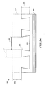
FIGs. 3A-3B depict graphical representations of a retention interface according to one or more embodiments. InFIG. 3A , a cross section ofretention interface 200 ofFIG. 2A is depicted along the line AA according to one embodiment.Retention interface 300 is formed to substrate 305 (e.g., substrate 105) and includes a pattern having a plurality of divots (e.g., divot 210). Theretention interface 300 is formed by an additive manufacturing process to include divots, such as divot 315 (e.g., divot 210).Thermal layer 320 is shown inFIG. 3A for illustration. According to one embodiment,thermal layer 320 may be built abovedivot 315 to aheight 330 which may be with in the range of 1 to 0.50 cm. -
Retention interface 300 includes a tapered divot pattern formed onbase layer 325.Divot 315 may have awidth 335 and aheight 345 abovebase layer 325.Divot 315 may be formed with aligament thickness 335 which may be tapered at the base ofdivot 335. Retention interface thickness,divot depth 345, divot spacing 340, andligament thickness 335 may be altered to aid in reducing heat and wear of a blade outer air seal. In certain embodiments, the transition between regions where theretention interface 300 is applied and thesubstrate 305 may be at least one of a planar and non-planar transition.Thermal layer 320 may be formed toretention interface 300 and may have a uniform or varyinglayer thickness 330. -
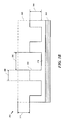
FIG. 3B depicts a cross section ofretention interface 200 ofFIG. 2A along the line AA according to another embodiment.Retention interface 350 is formed to substrate 305 (e.g., substrate 105) and includes plurality of divots (e.g., divot 210). Theretention interface 350 is formed by an additive manufacturing process to include divots, such as divot 360 (e.g., divot 210).Thermal layer 365 is shown inFIG. 3B for illustration. According to one embodiment,thermal layer 365 may be built abovedivot 360 by a height of 375 which may be with in the range of 1 to 0.5 cm. -
Retention interface 350 includes a uniform thickness divot pattern formed onbase layer 370.Divot 360 may have awidth 380 and aheight 345 abovebase layer 370.Divot 360 may be formed with aligament thickness 380 which may be of a uniform thickness. Retention interface thickness,divot depth 345, divot spacing 385, andligament thickness 380 may be altered to aid in reducing heat and wear of a blade outer air seal. In certain embodiments, the transition between regions where theretention interface 300 is applied and thesubstrate 305 may be at least one of a planar and non-planar transition.Thermal layer 365 may be formed toretention interface 350 and may have a uniform or varyinglayer thickness 375. -
FIG. 4 depicts a process for manufacturing a gas turbine engine component, such as a blade outer air seal, according to one or more embodiments.Process 400 may be employed during manufacture of a blade outer air seal segment (e.g., blade outer air seal 100). In certain embodiments, blade out air seals may be may be manufactured as segments to simplify manufacture and coating of parts.Process 400 may be initiated by forming a retention interface atblock 405. In one embodiment, the retention interface (e.g., retention interface 110) is formed by an additive manufacturing process to include a divot pattern atblock 405. The divot pattern may be formed on a surface of a substrate atblock 405 by at least one of direct metal laser sintering, laser spray metal deposition, laser processing and metal deposition general. In one embodiment, the retention interface is formed to a substrate with a thickness within the range of 1 to 50 µm. According to another embodiment, forming the retention interface to a substrate atblock 405 includes formation of the retention interface to the entirety of the substrate. Alternatively, the retention interface to a substrate may be applied to discrete sections of the substrate. - According to another embodiment, forming the retention interface to a substrate at
block 405 includes building divots by computer to control at least one of direct metal laser sintering, laser spray metal deposition, laser processing and metal deposition general. The retention interface may be formed to a substrate by building a single layer at a time in at least one direction and each additional layer is built onto the previous constructed layer. Formation atblock 405 may include forming a ligament thickness of each divot to one of a uniform thickness and a tapered thickness. In certain embodiments, a substrate of a blade outer air seal may include a transition between regions where the retention interface is applied and the substrate. The transition may be at least one of a planar, and non-planar transition. - At
block 410, a thermal barrier may be formed on the retention interface. The thermal barrier may be formed of Yttria-Stabilized Zirconia, or other elements. -
FIGs. 5A-5B depict graphical representations of blade outer air seal according to one or more other embodiments. -
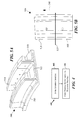
FIG. 5A depicts a blade outer air seal duct segment wherein a retention interface is formed on one or more discrete sections of the substrate according to one or more embodiments. Bladeouter air seal 500 includessubstrate 505 andduct segments 510 including a retention interface and thermal barrier layer. In that fashion, a retention interface may be applied to one or more discrete sections of bladeouter air seal 500.Retention regions 510 may be juxtaposed tonon-retention regions 505. In certain embodiments, the transition betweenretention regions 510 andnon-retention regions 505 may be at least one of a planar and non-planar transition.FIG. 5A depicts bladeouter air seal 500 as shrouded. -
FIG. 5B depicts a graphical representation of a transition betweenretention interface region 510 andsubstrate 505. According to one embodiment,transition 535 may be one of planar and non-planar, wherein the retention interface and thermal barrier is applied inbuild direction 540. - While this disclosure has been particularly shown and described with references to exemplary embodiments thereof, it will be understood by those skilled in the art that various changes in form and details may be made therein without departing from the scope of the claimed embodiments.
Claims (14)
- A gas turbine engine component (100) comprising:a substrate (105;305);a retention interface (110;205;300;350) formed on a surface of the substrate (105;300), wherein the retention interface (110;205;300;350) is formed by an additive manufacturing process to include a pattern; anda thermal barrier layer (116;365) formed to the retention interface (110;205;300;350).
- A method of manufacturing a turbine engine component comprising:forming a retention interface (110;205;300;350) to a substrate (105;300), wherein the retention interface (110;205;300;350) is formed by an additive manufacturing process to include a pattern; andforming a thermal barrier layer (116;365) on the retention interface (110;205;300;350).
- The gas turbine engine component or method of claim 1 or 2, wherein the gas turbine engine component (100) is at least one of a blade outer air seal, vane, turbine frame, and casing.
- The gas turbine engine component or method of any preceding claim, wherein the substrate (105;305) is one or more structural layers or elements of the gas turbine engine component.
- The gas turbine engine component or method of any preceding claim, wherein the retention interface (110;205;300;350) is formed by at least one of direct metal laser sintering, laser spray metal deposition, laser processing and metal deposition.
- The gas turbine engine component or method of any preceding claim, wherein the retention interface (110;205;300;350) has a thickness within the range of 1 to 50 µm.
- The gas turbine engine component or method of any preceding claim, wherein the retention interface (110;205;300;350) is applied to the entirety of the substrate.
- The gas turbine engine component or method of any preceding claim, wherein the retention interface (110;205;300;350) is applied to one or more discrete sections of the substrate (105;300).
- The gas turbine engine component or method of any preceding claim, wherein the pattern includes a base layer (125;205;325) and a plurality of divots (130; 135;225;315) formed on the base layer (125;205;325).
- The gas turbine engine component or method of claim 9, wherein a ligament thickness (335;380) of each divot is one of a uniform thickness and a tapered thickness.
- The gas turbine engine component or method of any preceding claim, further comprising (forming) a transition between regions where the retention interface is applied and the substrate, wherein the transition is at least one of a planar, and non-planar transition.
- The method of any of claims 2 to 11, including forming the retention interface (110;205;300;350) to a substrate (105;300) is built by a computer controlled at least one of direct metal laser sintering, laser spray metal deposition, laser processing and metal deposition general.
- The method of any of claims 2 to 12, including forming the retention interface (110;205;300;350) to a substrate (105;300) by building in at least one direction a single layer at a time and each additional layer is built onto the previous constructed layer.
- The method of any of claims 2 to 13, including forming the retention interface (110;205;300;350) to a substrate (105;300) includes forming a ligament thickness for each divot having one of a uniform thickness and a tapered thickness.
Applications Claiming Priority (1)
| Application Number | Priority Date | Filing Date | Title |
|---|---|---|---|
| US201462008173P | 2014-06-05 | 2014-06-05 |
Publications (1)
| Publication Number | Publication Date |
|---|---|
| EP2952341A1 true EP2952341A1 (en) | 2015-12-09 |
Family
ID=53546500
Family Applications (1)
| Application Number | Title | Priority Date | Filing Date |
|---|---|---|---|
| EP15170438.4A Withdrawn EP2952341A1 (en) | 2014-06-05 | 2015-06-03 | Blade outer air seal and method of manufacture |
Country Status (2)
| Country | Link |
|---|---|
| US (1) | US20150354406A1 (en) |
| EP (1) | EP2952341A1 (en) |
Cited By (1)
| Publication number | Priority date | Publication date | Assignee | Title |
|---|---|---|---|---|
| US10995620B2 (en) | 2018-06-21 | 2021-05-04 | General Electric Company | Turbomachine component with coating-capturing feature for thermal insulation |
Families Citing this family (3)
| Publication number | Priority date | Publication date | Assignee | Title |
|---|---|---|---|---|
| US10247106B2 (en) | 2016-06-15 | 2019-04-02 | General Electric Company | Method and system for rotating air seal with integral flexible heat shield |
| DE102017211316A1 (en) | 2017-07-04 | 2019-01-10 | MTU Aero Engines AG | Turbomachinery sealing ring |
| US10801353B2 (en) * | 2019-02-08 | 2020-10-13 | Raytheon Technologies Corporation | Divot pattern for thermal barrier coating |
Citations (6)
| Publication number | Priority date | Publication date | Assignee | Title |
|---|---|---|---|---|
| US5419971A (en) * | 1993-03-03 | 1995-05-30 | General Electric Company | Enhanced thermal barrier coating system |
| US20050158590A1 (en) * | 2004-01-16 | 2005-07-21 | Honeywell International Inc. | Atomic layer deposition for turbine components |
| US20090017260A1 (en) * | 2001-08-02 | 2009-01-15 | Kulkarni Anand A | Segmented thermal barrier coating |
| US20130101761A1 (en) * | 2011-10-21 | 2013-04-25 | General Electric Company | Components with laser cladding and methods of manufacture |
| DE102013110381A1 (en) * | 2012-09-28 | 2014-04-03 | General Electric Company | Layer arrangement, hot gas path component and method for producing a layer arrangement |
| WO2014144152A1 (en) * | 2013-03-15 | 2014-09-18 | Rolls-Royce Corporation | Improved coating interface |
Family Cites Families (6)
| Publication number | Priority date | Publication date | Assignee | Title |
|---|---|---|---|---|
| US6224963B1 (en) * | 1997-05-14 | 2001-05-01 | Alliedsignal Inc. | Laser segmented thick thermal barrier coatings for turbine shrouds |
| US8852720B2 (en) * | 2009-07-17 | 2014-10-07 | Rolls-Royce Corporation | Substrate features for mitigating stress |
| US8506243B2 (en) * | 2009-11-19 | 2013-08-13 | United Technologies Corporation | Segmented thermally insulating coating |
| US9272365B2 (en) * | 2012-09-12 | 2016-03-01 | Siemens Energy, Inc. | Superalloy laser cladding with surface topology energy transfer compensation |
| US20160032766A1 (en) * | 2013-03-14 | 2016-02-04 | General Electric Company | Components with micro cooled laser deposited material layer and methods of manufacture |
| US9151175B2 (en) * | 2014-02-25 | 2015-10-06 | Siemens Aktiengesellschaft | Turbine abradable layer with progressive wear zone multi level ridge arrays |
-
2015
- 2015-05-08 US US14/707,800 patent/US20150354406A1/en not_active Abandoned
- 2015-06-03 EP EP15170438.4A patent/EP2952341A1/en not_active Withdrawn
Patent Citations (6)
| Publication number | Priority date | Publication date | Assignee | Title |
|---|---|---|---|---|
| US5419971A (en) * | 1993-03-03 | 1995-05-30 | General Electric Company | Enhanced thermal barrier coating system |
| US20090017260A1 (en) * | 2001-08-02 | 2009-01-15 | Kulkarni Anand A | Segmented thermal barrier coating |
| US20050158590A1 (en) * | 2004-01-16 | 2005-07-21 | Honeywell International Inc. | Atomic layer deposition for turbine components |
| US20130101761A1 (en) * | 2011-10-21 | 2013-04-25 | General Electric Company | Components with laser cladding and methods of manufacture |
| DE102013110381A1 (en) * | 2012-09-28 | 2014-04-03 | General Electric Company | Layer arrangement, hot gas path component and method for producing a layer arrangement |
| WO2014144152A1 (en) * | 2013-03-15 | 2014-09-18 | Rolls-Royce Corporation | Improved coating interface |
Cited By (1)
| Publication number | Priority date | Publication date | Assignee | Title |
|---|---|---|---|---|
| US10995620B2 (en) | 2018-06-21 | 2021-05-04 | General Electric Company | Turbomachine component with coating-capturing feature for thermal insulation |
Also Published As
| Publication number | Publication date |
|---|---|
| US20150354406A1 (en) | 2015-12-10 |
Similar Documents
| Publication | Publication Date | Title |
|---|---|---|
| US10563517B2 (en) | Gas turbine engine v-shaped film cooling hole | |
| JP5728017B2 (en) | Machine and method with wearable ridges | |
| EP2841710B2 (en) | Gas turbine engine core providing exterior airfoil portion | |
| EP2841703B1 (en) | Gas turbine engine airfoil geometries and cores for manufacturing process | |
| US10815827B2 (en) | Variable thickness core for gas turbine engine component | |
| US9644489B1 (en) | Additive manufacturing of abradable mesh structure on ring segment surface | |
| US20130280092A1 (en) | Airfoil cooling enhancement and method of making the same | |
| CN102913290A (en) | System and method for passively controlling clearance in a gas turbine engine | |
| EP1878876A2 (en) | Gas turbine abradable seal | |
| US10215033B2 (en) | Stator seal for turbine rub avoidance | |
| US20160341051A1 (en) | Gas turbine engine component with an abrasive coating | |
| EP2859976A1 (en) | Machining tool and method for abradable coating pattern | |
| EP2952341A1 (en) | Blade outer air seal and method of manufacture | |
| JP6961043B2 (en) | How to manufacture turbo machine components, turbo machine components, and turbo machines | |
| US7665961B2 (en) | Turbine outer air seal | |
| US20210254475A1 (en) | Additive supports with integral film cooling | |
| EP2955327B1 (en) | A blade tip sealing assembly | |
| JP6947851B2 (en) | Turbine blades with skiler tips and high density oxide dispersion reinforcement layers | |
| US20190195080A1 (en) | Ceramic coating system and method | |
| US10544699B2 (en) | System and method for minimizing the turbine blade to vane platform overlap gap | |
| US10702964B2 (en) | Blade outer air seal surface | |
| GB2627749A (en) | A ring segment for a gas turbine, a method to operate a gas turbine and computer-implemented method to design and/or manufacture said ring segments | |
| JP2010203309A (en) | Steam turbine moving blade and method for manufacturing the same |
Legal Events
| Date | Code | Title | Description |
|---|---|---|---|
| PUAI | Public reference made under article 153(3) epc to a published international application that has entered the european phase |
Free format text: ORIGINAL CODE: 0009012 |
|
| AK | Designated contracting states |
Kind code of ref document: A1 Designated state(s): AL AT BE BG CH CY CZ DE DK EE ES FI FR GB GR HR HU IE IS IT LI LT LU LV MC MK MT NL NO PL PT RO RS SE SI SK SM TR |
|
| AX | Request for extension of the european patent |
Extension state: BA ME |
|
| 17P | Request for examination filed |
Effective date: 20160607 |
|
| RBV | Designated contracting states (corrected) |
Designated state(s): AL AT BE BG CH CY CZ DE DK EE ES FI FR GB GR HR HU IE IS IT LI LT LU LV MC MK MT NL NO PL PT RO RS SE SI SK SM TR |
|
| RAP1 | Party data changed (applicant data changed or rights of an application transferred) |
Owner name: UNITED TECHNOLOGIES CORPORATION |
|
| STAA | Information on the status of an ep patent application or granted ep patent |
Free format text: STATUS: EXAMINATION IS IN PROGRESS |
|
| 17Q | First examination report despatched |
Effective date: 20181210 |
|
| RAP1 | Party data changed (applicant data changed or rights of an application transferred) |
Owner name: RAYTHEON TECHNOLOGIES CORPORATION |
|
| STAA | Information on the status of an ep patent application or granted ep patent |
Free format text: STATUS: THE APPLICATION IS DEEMED TO BE WITHDRAWN |
|
| 18D | Application deemed to be withdrawn |
Effective date: 20210323 |