EP2952244A1 - Carbon capture system and method for capturing carbon dioxide - Google Patents
Carbon capture system and method for capturing carbon dioxide Download PDFInfo
- Publication number
- EP2952244A1 EP2952244A1 EP14170724.0A EP14170724A EP2952244A1 EP 2952244 A1 EP2952244 A1 EP 2952244A1 EP 14170724 A EP14170724 A EP 14170724A EP 2952244 A1 EP2952244 A1 EP 2952244A1
- Authority
- EP
- European Patent Office
- Prior art keywords
- carbon dioxide
- sorbent
- calciner
- carbonator
- furnace
- Prior art date
- Legal status (The legal status is an assumption and is not a legal conclusion. Google has not performed a legal analysis and makes no representation as to the accuracy of the status listed.)
- Granted
Links
Images

Classifications
-
- B—PERFORMING OPERATIONS; TRANSPORTING
- B01—PHYSICAL OR CHEMICAL PROCESSES OR APPARATUS IN GENERAL
- B01D—SEPARATION
- B01D53/00—Separation of gases or vapours; Recovering vapours of volatile solvents from gases; Chemical or biological purification of waste gases, e.g. engine exhaust gases, smoke, fumes, flue gases, aerosols
- B01D53/34—Chemical or biological purification of waste gases
- B01D53/46—Removing components of defined structure
- B01D53/62—Carbon oxides
-
- B—PERFORMING OPERATIONS; TRANSPORTING
- B01—PHYSICAL OR CHEMICAL PROCESSES OR APPARATUS IN GENERAL
- B01D—SEPARATION
- B01D53/00—Separation of gases or vapours; Recovering vapours of volatile solvents from gases; Chemical or biological purification of waste gases, e.g. engine exhaust gases, smoke, fumes, flue gases, aerosols
- B01D53/34—Chemical or biological purification of waste gases
- B01D53/73—After-treatment of removed components
-
- B—PERFORMING OPERATIONS; TRANSPORTING
- B01—PHYSICAL OR CHEMICAL PROCESSES OR APPARATUS IN GENERAL
- B01D—SEPARATION
- B01D53/00—Separation of gases or vapours; Recovering vapours of volatile solvents from gases; Chemical or biological purification of waste gases, e.g. engine exhaust gases, smoke, fumes, flue gases, aerosols
- B01D53/34—Chemical or biological purification of waste gases
- B01D53/74—General processes for purification of waste gases; Apparatus or devices specially adapted therefor
- B01D53/81—Solid phase processes
-
- B—PERFORMING OPERATIONS; TRANSPORTING
- B01—PHYSICAL OR CHEMICAL PROCESSES OR APPARATUS IN GENERAL
- B01D—SEPARATION
- B01D53/00—Separation of gases or vapours; Recovering vapours of volatile solvents from gases; Chemical or biological purification of waste gases, e.g. engine exhaust gases, smoke, fumes, flue gases, aerosols
- B01D53/34—Chemical or biological purification of waste gases
- B01D53/74—General processes for purification of waste gases; Apparatus or devices specially adapted therefor
- B01D53/81—Solid phase processes
- B01D53/83—Solid phase processes with moving reactants
-
- C—CHEMISTRY; METALLURGY
- C04—CEMENTS; CONCRETE; ARTIFICIAL STONE; CERAMICS; REFRACTORIES
- C04B—LIME, MAGNESIA; SLAG; CEMENTS; COMPOSITIONS THEREOF, e.g. MORTARS, CONCRETE OR LIKE BUILDING MATERIALS; ARTIFICIAL STONE; CERAMICS; REFRACTORIES; TREATMENT OF NATURAL STONE
- C04B7/00—Hydraulic cements
- C04B7/36—Manufacture of hydraulic cements in general
- C04B7/364—Avoiding environmental pollution during cement-manufacturing
- C04B7/367—Avoiding or minimising carbon dioxide emissions
-
- B—PERFORMING OPERATIONS; TRANSPORTING
- B01—PHYSICAL OR CHEMICAL PROCESSES OR APPARATUS IN GENERAL
- B01D—SEPARATION
- B01D2251/00—Reactants
- B01D2251/40—Alkaline earth metal or magnesium compounds
- B01D2251/404—Alkaline earth metal or magnesium compounds of calcium
-
- B—PERFORMING OPERATIONS; TRANSPORTING
- B01—PHYSICAL OR CHEMICAL PROCESSES OR APPARATUS IN GENERAL
- B01D—SEPARATION
- B01D2251/00—Reactants
- B01D2251/60—Inorganic bases or salts
- B01D2251/602—Oxides
-
- B—PERFORMING OPERATIONS; TRANSPORTING
- B01—PHYSICAL OR CHEMICAL PROCESSES OR APPARATUS IN GENERAL
- B01D—SEPARATION
- B01D2257/00—Components to be removed
- B01D2257/50—Carbon oxides
- B01D2257/504—Carbon dioxide
-
- B—PERFORMING OPERATIONS; TRANSPORTING
- B01—PHYSICAL OR CHEMICAL PROCESSES OR APPARATUS IN GENERAL
- B01D—SEPARATION
- B01D2258/00—Sources of waste gases
- B01D2258/02—Other waste gases
- B01D2258/0283—Flue gases
-
- B—PERFORMING OPERATIONS; TRANSPORTING
- B01—PHYSICAL OR CHEMICAL PROCESSES OR APPARATUS IN GENERAL
- B01D—SEPARATION
- B01D2259/00—Type of treatment
- B01D2259/65—Employing advanced heat integration, e.g. Pinch technology
-
- B—PERFORMING OPERATIONS; TRANSPORTING
- B01—PHYSICAL OR CHEMICAL PROCESSES OR APPARATUS IN GENERAL
- B01D—SEPARATION
- B01D53/00—Separation of gases or vapours; Recovering vapours of volatile solvents from gases; Chemical or biological purification of waste gases, e.g. engine exhaust gases, smoke, fumes, flue gases, aerosols
- B01D53/02—Separation of gases or vapours; Recovering vapours of volatile solvents from gases; Chemical or biological purification of waste gases, e.g. engine exhaust gases, smoke, fumes, flue gases, aerosols by adsorption, e.g. preparative gas chromatography
- B01D53/06—Separation of gases or vapours; Recovering vapours of volatile solvents from gases; Chemical or biological purification of waste gases, e.g. engine exhaust gases, smoke, fumes, flue gases, aerosols by adsorption, e.g. preparative gas chromatography with moving adsorbents, e.g. rotating beds
- B01D53/08—Separation of gases or vapours; Recovering vapours of volatile solvents from gases; Chemical or biological purification of waste gases, e.g. engine exhaust gases, smoke, fumes, flue gases, aerosols by adsorption, e.g. preparative gas chromatography with moving adsorbents, e.g. rotating beds according to the "moving bed" method
-
- B—PERFORMING OPERATIONS; TRANSPORTING
- B01—PHYSICAL OR CHEMICAL PROCESSES OR APPARATUS IN GENERAL
- B01D—SEPARATION
- B01D53/00—Separation of gases or vapours; Recovering vapours of volatile solvents from gases; Chemical or biological purification of waste gases, e.g. engine exhaust gases, smoke, fumes, flue gases, aerosols
- B01D53/34—Chemical or biological purification of waste gases
- B01D53/96—Regeneration, reactivation or recycling of reactants
-
- Y—GENERAL TAGGING OF NEW TECHNOLOGICAL DEVELOPMENTS; GENERAL TAGGING OF CROSS-SECTIONAL TECHNOLOGIES SPANNING OVER SEVERAL SECTIONS OF THE IPC; TECHNICAL SUBJECTS COVERED BY FORMER USPC CROSS-REFERENCE ART COLLECTIONS [XRACs] AND DIGESTS
- Y02—TECHNOLOGIES OR APPLICATIONS FOR MITIGATION OR ADAPTATION AGAINST CLIMATE CHANGE
- Y02C—CAPTURE, STORAGE, SEQUESTRATION OR DISPOSAL OF GREENHOUSE GASES [GHG]
- Y02C20/00—Capture or disposal of greenhouse gases
- Y02C20/40—Capture or disposal of greenhouse gases of CO2
-
- Y—GENERAL TAGGING OF NEW TECHNOLOGICAL DEVELOPMENTS; GENERAL TAGGING OF CROSS-SECTIONAL TECHNOLOGIES SPANNING OVER SEVERAL SECTIONS OF THE IPC; TECHNICAL SUBJECTS COVERED BY FORMER USPC CROSS-REFERENCE ART COLLECTIONS [XRACs] AND DIGESTS
- Y02—TECHNOLOGIES OR APPLICATIONS FOR MITIGATION OR ADAPTATION AGAINST CLIMATE CHANGE
- Y02P—CLIMATE CHANGE MITIGATION TECHNOLOGIES IN THE PRODUCTION OR PROCESSING OF GOODS
- Y02P40/00—Technologies relating to the processing of minerals
- Y02P40/10—Production of cement, e.g. improving or optimising the production methods; Cement grinding
- Y02P40/18—Carbon capture and storage [CCS]
Definitions
- the present invention relates to a carbon capture system and method for capturing carbon dioxide.
- Cement production occurs by clinkering a raw material typically including limestone CaCO 3 (as a source of calcium oxide CaO), and clay, marl or shale (as source of SiO 2 , Al 2 O 3 , Fe 2 O 3 ) and typically also other materials such as sand.
- limestone CaCO 3 as a source of calcium oxide CaO
- clay marl or shale
- SiO 2 , Al 2 O 3 , Fe 2 O 3 typically also other materials such as sand.
- a coupled carbon capture and cement production occurs over the following steps:
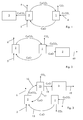
- Figure 1 shows a simplified block flow diagram representing a state of the art process scheme for cement production coupled with a carbon dioxide capture process. It includes a Calciner 1, a Carbonator 2 and a kiln 3.
- Raw material containing limestone CaCO 3 is supplied from a raw material supply 4 into the Calciner 1 where the make-up sorbent (mainly CaCO 3 ) is calcined (decomposed by heat) along with CaCO 3 from the Carbonator according to the reaction CaCO 3 ⁇ CaO + CO 2 generating carbon dioxide CO 2 and carbon dioxide lean sorbent CaO.
- the lean sorbent CaO is supplied to the Carbonator 2 where carbon dioxide CO 2 is captured from flue gas 5 according to the carbonation reaction CaO + CO 2 ⁇ CaCO 3 .
- Gas 6 deprived from carbon dioxide CO 2 is discharged from the Carbonator 2.
- the calcium carbonate CaCO 3 generated at the Carbonator 2 is supplied back into the Calciner 1 allowing the release of captured Carbon dioxide and sorbent regeneration.
- the carbon containing flue gas 5 may be attributed to a variety of thermally driven processes, such as power generation but a quantity of the flue gas will always be attributed to the cement process.
- flue gas is generated by combustion of a fuel with air; in addition carbon dioxide CO 2 is released during the clinkering reactions due to the residual carbon content of the feed material leaving the Carbonator 2 on route to the Kiln 3.
- Figure 6 shows that after some adsorption/desorption cycles, the calcium oxide CaO loses its capacity to adsorb carbon dioxide CO 2; for this reason it must be purged.
- purging is made by discharging calcined raw material containing calcium carbonate CaCO 3 from the Carbonator 2 and supplying it to the kiln 3 for calcination and thus clinkering.
- Figure 2 shows a second simplified block flow diagram representing a state of the art process scheme for cement production. It is similar to the scheme of figure 1 and same numbers indicates same or similar components.
- the scheme of figure 2 differs from the scheme of figure 1 in that purging is made by discharging raw material containing calcium oxide CaO from the Calciner 1 and supplying it to the kiln 3.
- This second scheme reduces the amount of circulating carbon dioxide, because a reduced amount of carbon dioxide is released at the kiln (because additional calcination of CaCO 3 associated with carbon dioxide captured from the flue gas is avoided); nevertheless fresh and highly active calcium oxide CaO (sorbent) that can be most efficiently used for carbon capture is purged unselectively together with deactivated or spent sorbent (i.e. sorbent that has a reduced capacity to adsorb carbon dioxide).
- An aspect of the invention includes providing a system and a method that improve sorbent activity by avoiding or at lest reducing unselectively purging of fresh and highly active sorbent and at the same time limit the circulation of carbon dioxide.
- FIG 3 shows a carbon capture system comprising a first Calciner 1 and a Carbonator 2.
- the Carbonator 2 is for adsorbing carbon dioxide from flue gas by employing a lean sorbent in order to generate a more rich sorbent.
- composition of the lean and rich sorbent is dependent on system design and system operational parameters (such as the ratio of make-up flow to recirculation flow) in addition to the deactivation characteristic of the material.
- the mole fraction of CO 2 bound to available Ca in the particle is typically less than 0.2 (corresponding to between 10 and 20 sorbent cycles in figure 8.
- lean and rich solvent are not made of only CaO and CaCO 3 but they are mixtures including mainly CaO or CaCO 3 and other materials; for example the lean sorbent has CaO as the main component, but may also contain CaCO 3 and similarly the rich sorbent may also contain CaO.
- the first Calciner 1 is for desorbing the carbon dioxide rich sorbent CaCO 3 from the carbon dioxide CO 2 generating the carbon dioxide lean sorbent CaO.
- the first Calciner 1 has a supply 4 of raw material to be calcined and a connection 13 between the first Calciner 1 and the Carbonator 2 for transferring the calcined raw material including the carbon dioxide lean sorbent CaO to the Carbonator 2.
- the system has a second Calciner 15 for desorbing a carbon dioxide rich sorbent CaCO 3 from carbon dioxide CO 2 generating a carbon dioxide lean sorbent CaO, and connections 16 and 17 between the Carbonator 2 and the second Calciner 15.
- connection 16 between the Carbonator 2 and the second Calciner 15 is for transferring the carbon dioxide rich sorbent CaCO 3 to the second Calciner 15, and the connection 17 between the second Calciner 15 and the Carbonator 2 is for transferring carbon dioxide lean sorbent CaO back to the Carbonator 2 for renewed capture of carbon dioxide CO 2 .
- the system can be used in a number of different applications, for this reason the Carbonator 2 can be supplied with flue gas containing carbon dioxide CO 2 to be captured and separated from the flue gas.
- the system is used in a cement production plant; for this reason there are also provided a kiln 3 for cement production and a connection 18 between the second Calciner 15 and the kiln 3 for transferring carbon dioxide lean sorbent CaO to the kiln 3.
- Ratio Moles of CaO obtained by calcining the make-up sorbent (mainly CaCO 3 ) / Moles of sorbent (mostly CaO) required to capture CO 2 from a given flue gas.
- the ratio is typically above 1 for the schemes described in Figure 1-3 , and is well below 1 typically less than 0.05) for post combustion carbon dioxide capture (for example in power plants or industrial applications). Anyhow, the system provides benefits also for applications to industrially generated flue gas or flue gas from power generation.
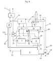
- Figures 4 shows the system more in detail; this system can for example be applied as a carbon capture retrofit solution for an existing cement plant; when describing this figure reference to CaO and CaCO 3 is made as one of the main components used in cement production and as the preferred sorbent. It is clear that in applications different from cement production the sorbent can be any appropriate sorbent known in the art of natural or synthetic origin.
- Figure 4 shows a raw material supply 4 (for e.g. raw meal containing CaCO 3 ) connected to one or more preheaters 21, 22; for example the preheater 21 represents a number of preheaters (for example four or five preheaters from an existing cement plant) for the raw material to be calcined.
- the preheater 21 heats the raw material by cooling a mixture of carbon dioxide rich flue gas originating from the kiln 3 via a line 23 and carbon dioxide lean flue gas from the Carbonator 2 via a line 24.
- the kiln gas is bypassed to the preheater 21 of the existing plant to ensure the required operating pressure (under atmospheric pressure, vacuum conditions).
- the preheater 22 heats the raw material by cooling the carbon dioxide discharged from the first and second Calciners 1 and 15 via the lines 29, 30.
- the preheater 22 is connected to the first Calciner 1 for supplying the raw material (preheated raw material).
- a solid/solid heat exchanger 31 is provided, for heating the carbon dioxide rich sorbent CaCO 3 moving from the Carbonator 2 to the second Calciner 15 by cooling the carbon dioxide lean sorbent CaO moving from the first Calciner 1 and/or the second Calciner 15 to the Carbonator 2.
- the second Calciner 15 is connected with the kiln 3 via the connection 32 and with the Carbonator 2 via the connection 33.
- a separator 34 is provided connected on the line 23, between the kiln 3 and the preheater 21; the separator 34 separates the solid particles possibly contained in the flue gas from the kiln 3 and forwards them back to the kiln 3 via a line 52.
- a furnace 35 for example air fired furnace
- the furnace 35 heats solids that are circulated via connection lines 36 between the furnace 35 and the first Calciner 1 and via connection lines 38 between the furnace 35 and the second Calciner 15.
- connection lines 36 between the furnace 35 and the first Calciner 1 and via connection lines 38 between the furnace 35 and the second Calciner 15.
- each Calciner 1, 15 can have a furnace or indirect heat transfer schemes without solids circulation, or direct fired (oxy-fuel) calcination can be implemented.
- a connection 39 is provided between the furnace 35 and the Carbonator 2, for supplying flue gas generated in the furnace 35 by combusting a fuel into the Carbonator 2.
- a heat exchanger 40 is provided on the connection 39, for preheating the air (or oxidizer) supplied into the furnace 35 via a line 42 by cooling flue gas discharged from the furnace 35 via the line 39; an additional line 43 can be provided to supply preheated air (or oxidizer, generated from cooling clinker exiting the kiln 3) to the furnace 35, bypassing the heat exchanger 40.
- a heat exchanger 45 is also preferentially provided in addition to or in place of the heat exchanger 40, in order to preheat solids supplied via a line 46 to the furnace 35 by cooling the flue gas discharged from the furnace 35 via the line 39.
- the preheater 45 functions in a counter current manner heating the hot solids which enter at the top via line 46 and fall via gravity through the rising cooling flue gas from furnace 35.
- the line 46 can originate from the line 36 forwarding solids from the Calciner 1 into the furnace 35 and/or from the line 38 forwarding the solids from the calciner 15 into the furnace 35.
- the kiln 3 is connected to a heat exchanger 48 for cooling the clinker 49 discharged from the kiln 3 by heating the fresh oxidizer such as air; the heat exchanger 48 is then connected via the connections 42, 43 to the furnace 35 for supplying the heated air (or oxidizer) into the furnace 35, and via a connection 50 to a fuel drying system, for drying solid fuel such as coal.
- the fuel drying system is then connected to the furnace 35 and kiln 3 in order to supply the required fuels.
- Raw material supply 4 supplies raw material to the preheaters 21 and 22 where it is heated and then supplied to the first Calciner 1.
- raw material is calcined (for example raw meal for cement production, it can be different for different applications). Since the raw material supplied to the first Calciner is fresh raw material additional time is required to calcine the sorbent.
- the Calciner 1 is designed accordingly so that the conversion CaCO 3 into CaO is almost complete (i.e. almost all CaCO 3 is converted into CaO). This conversion occurs according to the calcination reaction CaCO 3 ⁇ CaO + CO 2 usually at a temperature above 900°C, preferably about slightly above 900°C.
- the CaO is supplied to the Carbonator 2 where it adsorbs carbon dioxide from the flue gas coming from the furnace 35 (and possibly from flu gas generated in an industrial application or power plant); adsorption takes place according to the reaction CaO + CO 2 ⁇ CaCO 3 usually at a temperature between about 600-750°C. at the heat exchanger 31 CaO moving from the first Calciner 1 to the Carbonator 2 is cooled against rich sorbent CaCO 3 moving from the Carbonator 2 to the second Calciner 15; Rich sorbent CaCO 3 is thus forwarded to the second Calciner 15.
- CaO is thus supplied to the kiln 3 via the line 32 and partly to the Carbonator 2 via the line 33.
- Figure 6 shows the cycles that the CaO has undergone in a system according to figure 2 (curve A) and according to figures 3 and 4 (curve B). This figure shows that according to the invention ( figures 3 and 4 ) the CaO supplied to the Carbonator 2 undergoes less calcination / carbonation cycles and is therefore more reactive.
- the method of the invention provides an increased active fraction of circulating sorbent for the same sorbent molar flow (molar flow of CaO and CaCO 3 ).
- the method shown in figure 3 increases sorbent activity (mol CaCO 3 / mol CaO and CaCO 3 in the sorbent) by between 5 to 20%, typically above 10%. Ultimately this translates into a lower required sorbent circulation rate or smaller equipment.
- the furnace 35 combusts a fuel and generates hot solids that are circulated via lines 36 and 38 between the furnace 35 and the first and second Calciners 1 and 15.
- a part of the cooled solids returning from the Calciners (1 or 15) is diverted via the line 46 to be heated against flue gas discharged from the furnace 35 in the heat exchanger 45.
- the flue gas discharged from the furnace 35 is supplied into the Carbonator 2 (for carbon dioxide capture) after cooling via the heat exchangers 45 and 40.
- the carbon dioxide rich flue gas from the kiln 3 is supplied to the separator 34 via the line 23, where solid particles are separated from the gas and forwarded back to the kiln 3 via the line 52.
- the present invention also refers to a method for capturing carbon dioxide.
- the method comprises supplying a raw material containing a carbon dioxide rich sorbent such as CaCO 3 (but other sorbents are possible, CaCO 3 is preferably used when the method is implemented in connection with a kiln for cement production) into a first Calciner 1.
- a carbon dioxide rich sorbent such as CaCO 3
- CaCO 3 is preferably used when the method is implemented in connection with a kiln for cement production
- the raw material is calcined according to the calcination (decarbonation reaction) CaCO 3 ⁇ CaO + CO 2 that usually takes place at a temperature above 900°C, preferably about slightly above 900°C.
- the calcined raw material containing the carbon dioxide lean sorbent CaO is supplied to the Carbonator 2.
- flue gas is supplied into the Carbonator 2; the flue gas comes from the furnace 35, but in other applications can also come from an industrial process or a furnace of a power plant for electricity production.
- carbon dioxide from flue gas is adsorbed by the carbon dioxide lean sorbent CaO according to the carbonation reaction CaO + CO 2 ⁇ CaCO 3 that takes place at a temperature between about 600-750°C.
- the raw material containing carbon dioxide rich sorbent, namely CaCO 3 is in turn supplied to the second Calciner 15.
- the raw material containing carbon dioxide rich sorbent CaCO 3 is calcined according to the calcination (decarbonation reaction) CaCO 3 ⁇ CaO + CO 2 that usually takes place at a temperature above 900°C, preferably about slightly above 900°C.
- a part of the calcined raw material containing carbon dioxide lean sorbent CaO is supplied to the Carbonator 2.
- the additional Calciner 15 provides increased flexibility to consider increased calcination times ensuring complete calcination of make-up sorbent and ultimately increasing the sorbent activity (quantity CO 2 / quantity sorbent).
Landscapes
- Engineering & Computer Science (AREA)
- Chemical & Material Sciences (AREA)
- Environmental & Geological Engineering (AREA)
- Chemical Kinetics & Catalysis (AREA)
- Health & Medical Sciences (AREA)
- Oil, Petroleum & Natural Gas (AREA)
- General Chemical & Material Sciences (AREA)
- Analytical Chemistry (AREA)
- Biomedical Technology (AREA)
- Ceramic Engineering (AREA)
- Public Health (AREA)
- Materials Engineering (AREA)
- Structural Engineering (AREA)
- Organic Chemistry (AREA)
- Environmental Sciences (AREA)
- Ecology (AREA)
- Biodiversity & Conservation Biology (AREA)
- Life Sciences & Earth Sciences (AREA)
- Treating Waste Gases (AREA)
- Solid-Sorbent Or Filter-Aiding Compositions (AREA)
Abstract
Description
- The present invention relates to a carbon capture system and method for capturing carbon dioxide.
- Several systems and methods have been described previously which detail the capture of CO2 from flue gas. These systems and methods can be integrated into different applications, such as into an industrial application or into a power plant to capture carbon dioxide from flue gas. Due to the rapid deactivation of natural sorbent materials, such as limestone, a preferred and particularly advantageous application of the present system and method are in connection with the production of low carbon content feed material for downstream cement clinker production, such as in a rotary kiln. While in the following description particular advantage of the proposed scheme for cement production is made, it is anyhow clear that the application of the system and method are not limited to cement production.
- Cement production occurs by clinkering a raw material typically including limestone CaCO3 (as a source of calcium oxide CaO), and clay, marl or shale (as source of SiO2, Al2O3, Fe2O3) and typically also other materials such as sand.
- A coupled carbon capture and cement production occurs over the following steps:
- 1) Sorbent preparation; material milling and heat-treatment, such as the calcination of limestone to produce CaO (allowing capture of the chemically associated CO2 during calcination in the Calciner reactor);
- 2) Exposure of the sorbent powder to flue gas (possibly generated for the above mentioned heat treatment but also possibly from an external process) in order to convert CaO to CaCO3 by lowering the concentration of CO2 in the combustion flue gas through gas solid contact in the Carbonator reactor;
- 3) Regeneration of the sorbent materials, in particular the restoration of the CO2 capture capacity (quantity CO2 / quantity sorbent);
- 4) A sorbent purge to close the material balance of the cycle and remove deactivated sorbent from the system which is utilized for cement production.
- Considering the above steps,
Figure 1 shows a simplified block flow diagram representing a state of the art process scheme for cement production coupled with a carbon dioxide capture process. It includes a Calciner 1, aCarbonator 2 and akiln 3. Raw material containing limestone CaCO3 is supplied from araw material supply 4 into the Calciner 1 where the make-up sorbent (mainly CaCO3) is calcined (decomposed by heat) along with CaCO3 from the Carbonator according to the reaction
CaCO3 → CaO + CO2
generating carbon dioxide CO2 and carbon dioxide lean sorbent CaO. The lean sorbent CaO is supplied to theCarbonator 2 where carbon dioxide CO2 is captured fromflue gas 5 according to the carbonation reaction
CaO + CO2 → CaCO3.
-
Gas 6 deprived from carbon dioxide CO2 is discharged from theCarbonator 2. The calcium carbonate CaCO3 generated at theCarbonator 2 is supplied back into the Calciner 1 allowing the release of captured Carbon dioxide and sorbent regeneration. - The carbon containing
flue gas 5 may be attributed to a variety of thermally driven processes, such as power generation but a quantity of the flue gas will always be attributed to the cement process. At thekiln 3 flue gas is generated by combustion of a fuel with air; in addition carbon dioxide CO2 is released during the clinkering reactions due to the residual carbon content of the feed material leaving theCarbonator 2 on route to the Kiln 3. -
Figure 6 shows that after some adsorption/desorption cycles, the calcium oxide CaO loses its capacity to adsorb carbon dioxide CO2; for this reason it must be purged. - According to the scheme of
figure 1 , purging is made by discharging calcined raw material containing calcium carbonate CaCO3 from theCarbonator 2 and supplying it to thekiln 3 for calcination and thus clinkering. - As mentioned this scheme has the drawback that calcium carbonate CaCO3 formed in the Carbonator is calcined at the
kiln 3 which requires additional fuel combustion and produces additional CO2 associated with the chemically bound CO2 captured from the flue gas at theCarbonator 2. This causes an unnecessary carbon dioxide circulation between the Kiln and the Carbonator and consequently increased energy consumption and equipment dimensions and costs. -
Figure 2 shows a second simplified block flow diagram representing a state of the art process scheme for cement production. It is similar to the scheme offigure 1 and same numbers indicates same or similar components. The scheme offigure 2 differs from the scheme offigure 1 in that purging is made by discharging raw material containing calcium oxide CaO from theCalciner 1 and supplying it to thekiln 3. - This second scheme reduces the amount of circulating carbon dioxide, because a reduced amount of carbon dioxide is released at the kiln (because additional calcination of CaCO3 associated with carbon dioxide captured from the flue gas is avoided); nevertheless fresh and highly active calcium oxide CaO (sorbent) that can be most efficiently used for carbon capture is purged unselectively together with deactivated or spent sorbent (i.e. sorbent that has a reduced capacity to adsorb carbon dioxide).
- An aspect of the invention includes providing a system and a method that improve sorbent activity by avoiding or at lest reducing unselectively purging of fresh and highly active sorbent and at the same time limit the circulation of carbon dioxide.
- These and further aspects are attained by providing a system and a method in accordance with the accompanying claims.
- Further characteristics and advantages will be more apparent from the description of a preferred but non-exclusive embodiment of the system and method, illustrated by way of non-limiting example in the accompanying drawings, in which:
-
Figures 1 and 2 show examples of state of the art process schemes for Carbon capture coupled with cement production; -
Figure 3 shows a simplified block flow diagram representing a process scheme for carbon capture coupled with cement production according to the invention; -
Figure 4 shows a more detailed block flow diagram of an integrated carbon capture solution for cement production; -
Figure 5 is diagram showing the fraction of sorbent in the system having completed a given number of calcination and recarbonation cycles.Figure 5 represents the situation for the plant schemes offigure 2 (curve A) andfigure 3 (curve B) considering the material flows required to decarbonize cement production using the above mentioned methods; -
Figure 6 is a diagram showing the reduction of sorbent activity with an increasing number of calcination and recarbonation cycles. - With reference to
figure 3 , it shows a carbon capture system comprising afirst Calciner 1 and aCarbonator 2. - The
Carbonator 2 is for adsorbing carbon dioxide from flue gas by employing a lean sorbent in order to generate a more rich sorbent. - The composition of the lean and rich sorbent is dependent on system design and system operational parameters (such as the ratio of make-up flow to recirculation flow) in addition to the deactivation characteristic of the material. For deactivated rich sorbent the mole fraction of CO2 bound to available Ca in the particle is typically less than 0.2 (corresponding to between 10 and 20 sorbent cycles in figure 8.
- In the following reference to CaO as the carbon dioxide lean sorbent and CaCO3 as the carbon dioxide rich sorbent is made; other lean/rich sorbent can anyway be used. In addition it is clear that lean and rich solvent are not made of only CaO and CaCO3 but they are mixtures including mainly CaO or CaCO3 and other materials; for example the lean sorbent has CaO as the main component, but may also contain CaCO3 and similarly the rich sorbent may also contain CaO.
- The first Calciner 1 is for desorbing the carbon dioxide rich sorbent CaCO3 from the carbon dioxide CO2 generating the carbon dioxide lean sorbent CaO.
- The first Calciner 1 has a
supply 4 of raw material to be calcined and aconnection 13 between the first Calciner 1 and theCarbonator 2 for transferring the calcined raw material including the carbon dioxide lean sorbent CaO to theCarbonator 2. - In addition, the system has a second Calciner 15 for desorbing a carbon dioxide rich sorbent CaCO3 from carbon dioxide CO2 generating a carbon dioxide lean sorbent CaO, and
connections Carbonator 2 and the second Calciner 15. - The
connection 16 between theCarbonator 2 and the second Calciner 15 is for transferring the carbon dioxide rich sorbent CaCO3 to the second Calciner 15, and theconnection 17 between the second Calciner 15 and theCarbonator 2 is for transferring carbon dioxide lean sorbent CaO back to theCarbonator 2 for renewed capture of carbon dioxide CO2. - The system can be used in a number of different applications, for this reason the
Carbonator 2 can be supplied with flue gas containing carbon dioxide CO2 to be captured and separated from the flue gas. - Preferably, the system is used in a cement production plant; for this reason there are also provided a
kiln 3 for cement production and aconnection 18 between the second Calciner 15 and thekiln 3 for transferring carbon dioxide lean sorbent CaO to thekiln 3. - Application of the system in a plant for cement production is particularly advantageous because in this case the amount of make-up CaCO3 (supplied with fresh raw material) is very high compared to the amount of purged CaO (forwarded to the kiln). This can be shown with reference to the ratio of make-up molar sorbent flow to the molar sorbent circulation rate, defined by
- Ratio = Moles of CaO obtained by calcining the make-up sorbent (mainly CaCO3) / Moles of sorbent (mostly CaO) required to capture CO2 from a given flue gas.
- The ratio is typically above 1 for the schemes described in
Figure 1-3 , and is well below 1 typically less than 0.05) for post combustion carbon dioxide capture (for example in power plants or industrial applications). Anyhow, the system provides benefits also for applications to industrially generated flue gas or flue gas from power generation. -
Figures 4 shows the system more in detail; this system can for example be applied as a carbon capture retrofit solution for an existing cement plant; when describing this figure reference to CaO and CaCO3 is made as one of the main components used in cement production and as the preferred sorbent. It is clear that in applications different from cement production the sorbent can be any appropriate sorbent known in the art of natural or synthetic origin. -
Figure 4 shows a raw material supply 4 (for e.g. raw meal containing CaCO3) connected to one ormore preheaters preheater 21 represents a number of preheaters (for example four or five preheaters from an existing cement plant) for the raw material to be calcined. The preheater 21 heats the raw material by cooling a mixture of carbon dioxide rich flue gas originating from thekiln 3 via aline 23 and carbon dioxide lean flue gas from theCarbonator 2 via aline 24. For example the kiln gas is bypassed to thepreheater 21 of the existing plant to ensure the required operating pressure (under atmospheric pressure, vacuum conditions). - The preheater 22 heats the raw material by cooling the carbon dioxide discharged from the first and second Calciners 1 and 15 via the
lines - The
preheater 22 is connected to thefirst Calciner 1 for supplying the raw material (preheated raw material). - Between the first Calciner 1 and the
Carbonator 2, a solid/solid heat exchanger 31 is provided, for heating the carbon dioxide rich sorbent CaCO3 moving from theCarbonator 2 to thesecond Calciner 15 by cooling the carbon dioxide lean sorbent CaO moving from the first Calciner 1 and/or thesecond Calciner 15 to theCarbonator 2. - The
second Calciner 15 is connected with thekiln 3 via theconnection 32 and with theCarbonator 2 via theconnection 33. - In addition, preferably a
separator 34 is provided connected on theline 23, between thekiln 3 and thepreheater 21; theseparator 34 separates the solid particles possibly contained in the flue gas from thekiln 3 and forwards them back to thekiln 3 via aline 52. - In order to heat the first and second Calciners 1 and 15, a furnace 35 (for example air fired furnace) is provided; the
furnace 35 heats solids that are circulated viaconnection lines 36 between thefurnace 35 and the first Calciner 1 and viaconnection lines 38 between thefurnace 35 and thesecond Calciner 15. Naturally also different schemes are possible for heating theCalciners Calciner - A
connection 39 is provided between thefurnace 35 and theCarbonator 2, for supplying flue gas generated in thefurnace 35 by combusting a fuel into theCarbonator 2. Preferably, aheat exchanger 40 is provided on theconnection 39, for preheating the air (or oxidizer) supplied into thefurnace 35 via aline 42 by cooling flue gas discharged from thefurnace 35 via theline 39; anadditional line 43 can be provided to supply preheated air (or oxidizer, generated from cooling clinker exiting the kiln 3) to thefurnace 35, bypassing theheat exchanger 40. - A
heat exchanger 45 is also preferentially provided in addition to or in place of theheat exchanger 40, in order to preheat solids supplied via aline 46 to thefurnace 35 by cooling the flue gas discharged from thefurnace 35 via theline 39. Thepreheater 45 functions in a counter current manner heating the hot solids which enter at the top vialine 46 and fall via gravity through the rising cooling flue gas fromfurnace 35. Theline 46 can originate from theline 36 forwarding solids from theCalciner 1 into thefurnace 35 and/or from theline 38 forwarding the solids from thecalciner 15 into thefurnace 35. - The
kiln 3 is connected to aheat exchanger 48 for cooling theclinker 49 discharged from thekiln 3 by heating the fresh oxidizer such as air; theheat exchanger 48 is then connected via theconnections furnace 35 for supplying the heated air (or oxidizer) into thefurnace 35, and via aconnection 50 to a fuel drying system, for drying solid fuel such as coal. The fuel drying system is then connected to thefurnace 35 andkiln 3 in order to supply the required fuels. - The operation of the system is apparent from that described and illustrated and is substantially the following.
-
Raw material supply 4 supplies raw material to thepreheaters first Calciner 1. At thefirst Calciner 1 raw material is calcined (for example raw meal for cement production, it can be different for different applications). Since the raw material supplied to the first Calciner is fresh raw material additional time is required to calcine the sorbent. TheCalciner 1 is designed accordingly so that the conversion CaCO3 into CaO is almost complete (i.e. almost all CaCO3 is converted into CaO). This conversion occurs according to the calcination reaction
CaCO3 → CaO + CO2
usually at a temperature above 900°C, preferably about slightly above 900°C. - The CaO is supplied to the
Carbonator 2 where it adsorbs carbon dioxide from the flue gas coming from the furnace 35 (and possibly from flu gas generated in an industrial application or power plant); adsorption takes place according to the reaction
CaO + CO2 → CaCO3
usually at a temperature between about 600-750°C.
at theheat exchanger 31 CaO moving from thefirst Calciner 1 to theCarbonator 2 is cooled against rich sorbent CaCO3 moving from theCarbonator 2 to thesecond Calciner 15; Rich sorbent CaCO3 is thus forwarded to thesecond Calciner 15. - At the
second Calciner 15 carbon dioxide is released by thermal decomposition according to the calcination reaction
CaCO3 → CaO + CO2
usually at a temperature above 900°C, preferably about slightly above 900°C. - CaO is thus supplied to the
kiln 3 via theline 32 and partly to theCarbonator 2 via theline 33. - Since at the
Carbonator 2 there is a large amount of CaO coming from the first Calciner 1 (this is fresh CaO) and the amount of CaO from thesecond Calciner 15 is limited (because CaO is only purged from the second Calciner 15), the carbonation reaction at theCarbonator 2 is very efficient and the CaO can adsorb a large amount of carbon dioxide. -
Figure 6 shows the cycles that the CaO has undergone in a system according tofigure 2 (curve A) and according tofigures 3 and4 (curve B). This figure shows that according to the invention (figures 3 and4 ) the CaO supplied to theCarbonator 2 undergoes less calcination / carbonation cycles and is therefore more reactive. - Considering the decline in the activity of the sorbent according to
figure 6 , the method of the invention provides an increased active fraction of circulating sorbent for the same sorbent molar flow (molar flow of CaO and CaCO3). Considering the make-up rate of fresh sorbent (required for cement production), the method shown infigure 3 increases sorbent activity (mol CaCO3/ mol CaO and CaCO3 in the sorbent) by between 5 to 20%, typically above 10%. Ultimately this translates into a lower required sorbent circulation rate or smaller equipment. - The
furnace 35 combusts a fuel and generates hot solids that are circulated vialines furnace 35 and the first and second Calciners 1 and 15. Preferably a part of the cooled solids returning from the Calciners (1 or 15) is diverted via theline 46 to be heated against flue gas discharged from thefurnace 35 in theheat exchanger 45. The flue gas discharged from thefurnace 35 is supplied into the Carbonator 2 (for carbon dioxide capture) after cooling via theheat exchangers - The carbon dioxide rich flue gas from the
kiln 3 is supplied to theseparator 34 via theline 23, where solid particles are separated from the gas and forwarded back to thekiln 3 via theline 52. - The present invention also refers to a method for capturing carbon dioxide.
- The method comprises supplying a raw material containing a carbon dioxide rich sorbent such as CaCO3 (but other sorbents are possible, CaCO3 is preferably used when the method is implemented in connection with a kiln for cement production) into a
first Calciner 1. At thefirst Calciner 1, the raw material is calcined according to the calcination (decarbonation reaction)
CaCO3 → CaO + CO2
that usually takes place at a temperature above 900°C, preferably about slightly above 900°C. - Following the calcination reaction, a calcined raw material containing a carbon dioxide lean sorbent CaO is generated; in addition, also carbon dioxide is generated.
- The calcined raw material containing the carbon dioxide lean sorbent CaO is supplied to the
Carbonator 2. In addition, also flue gas is supplied into theCarbonator 2; the flue gas comes from thefurnace 35, but in other applications can also come from an industrial process or a furnace of a power plant for electricity production. - At the
Carbonator 2, carbon dioxide from flue gas is adsorbed by the carbon dioxide lean sorbent CaO according to the carbonation reaction
CaO + CO2 → CaCO3
that takes place at a temperature between about 600-750°C. - Following the carbonation reaction, a raw material containing a carbon dioxide rich sorbent CaCO3 is generated.
- The raw material containing carbon dioxide rich sorbent, namely CaCO3, is in turn supplied to the
second Calciner 15. - At the
second Calciner 15, the raw material containing carbon dioxide rich sorbent CaCO3 is calcined according to the calcination (decarbonation reaction)
CaCO3 → CaO + CO2
that usually takes place at a temperature above 900°C, preferably about slightly above 900°C. - Following the calcination reaction, calcined raw material containing carbon dioxide lean sorbent CaO and carbon dioxide are generated.
- A part of the calcined raw material containing carbon dioxide lean sorbent CaO is supplied to the
Carbonator 2. - When the method is used in connection with a kiln for cement production (preferred application) a part of the calcined raw material containing carbon dioxide lean sorbent CaO is transferred from the
second Calciner 15 to thekiln 3 for cement production. - The
additional Calciner 15 provides increased flexibility to consider increased calcination times ensuring complete calcination of make-up sorbent and ultimately increasing the sorbent activity (quantity CO2 / quantity sorbent). - Naturally the features described may be independently provided from one another.
- In practice the materials used and the dimensions can be chosen at will according to requirements and to the state of the art.
-
- 1
- Calciner
- 2
- Carbonator
- 3
- kiln
- 4
- raw material supply
- 5
- flue gas
- 6
- gas deprived from carbon dioxide
- 13
- connection
- 15
- second Calciner
- 16
- connection
- 17
- connection
- 18
- connection
- 21
- preheater
- 22
- preheater
- 23
- line
- 24
- line
- 29
- line
- 30
- line
- 31
- heat exchanger
- 32
- connection
- 33
- connection
- 34
- separator
- 35
- furnace
- 36
- connection line
- 38
- connection line
- 39
- connection
- 40
- heat exchanger
- 42
- line
- 43
- line
- 45
- heat exchanger
- 46
- line
- 48
- heat exchanger
- 49
- clinker
- 50
- connection
- 52
- line
- A
- cycles that the CaO has undergone in a system according to
figure 2 - B
- cycles that the CaO has undergone in a system according to
figures 3 and4
Claims (11)
- A carbon capture system comprising
a Carbonator (2) for adsorbing carbon dioxide with a carbon dioxide lean sorbent generating a carbon dioxide rich sorbent,
a first Calciner (1) for thermally decomposing a carbon dioxide rich sorbent into a carbon dioxide lean sorbent and carbon dioxide,
a supply of raw material (4) to be calcined into the first Calciner (1), the raw material containing a carbon dioxide rich sorbent,
a connection (13) between the first Calciner (1) and the Carbonator (2) for transferring at least the carbon dioxide lean sorbent to the Carbonator (2), characterised by further comprising
a second Calciner (15) for thermally decomposing a carbon dioxide rich sorbent into a carbon dioxide lean sorbent and carbon dioxide,
a connection (16) between the Carbonator (2) and the second Calciner (15) for transferring at least carbon dioxide rich sorbent to the second Calciner (15),
a connection (17) between the second Calciner (15) and the Carbonator (2) for transferring carbon dioxide lean sorbent (CaO) to the Carbonator (2). - A carbon capture system of claim 1, characterised by further comprising
a kiln (3) for cement production,
a connection (18) between the second Calciner (15) and the kiln (3) for transferring carbon dioxide lean sorbent to the Carbonator (2). - A carbon capture system of claim 1, characterised by further comprising a preheater (21, 22) for the raw material to be calcined.
- A carbon capture system of claim 1, characterised by further comprising a solid/solid heat exchanger (31) for heating the carbon dioxide rich sorbent moving from the Carbonator (2) to the second Calciner (15) by cooling the carbon dioxide lean sorbent moving from the first Calciner (1) and the second Calciner (15) to the Carbonator (2).
- A carbon capture system of claim 1, characterised by further comprising a furnace (35) for heating solids, and connection lines (36, 38) between the furnace (35) and the first and/or the second Calciner (1, 15), for circulating the solids between the first and second Calciner (1, 15) and the furnace (35).
- A carbon capture system of claim 5, characterised by further comprising a connection (39) between the furnace (35) and the Carbonator (2), for supplying flue gas generated in the furnace (35) by combusting a fuel into the Carbonator (2).
- A carbon capture system of claim 1, further comprising a heat exchanger (48) for cooling clinker discharged from the kiln (3) by heating fresh oxidizer, and at least a connection (42, 43) of the heat exchanger (48) to at least one of:- the furnace (35), for supplying the heated oxidizer into the furnace (35),- a fuel drying system.
- A carbon capture system of claim 7, wherein at least one of the at least a connection (42) to the furnace (35) is provided with a heat exchanger (40) for preheating the oxidizer supplied into the furnace (35) by cooling flue gas discharged from the furnace (35).
- A method for capturing carbon dioxide comprising supplying a raw material containing a carbon dioxide rich sorbent into a first Calciner (1),
at the first Calciner (1), thermally decomposing the carbon dioxide rich sorbent into a carbon dioxide lean sorbent and carbon dioxide,
supplying the calcined raw material containing the carbon dioxide lean sorbent to a Carbonator (2),
at the Carbonator (2), adsorbing carbon dioxide from flue gas generating a raw material containing a carbon dioxide rich sorbent,
characterised by
supplying the raw material containing the carbon dioxide rich sorbent into a second Calciner (15),
at the second Calciner (15), thermally decomposing the carbon dioxide rich sorbent into carbon dioxide lean sorbent and carbon dioxide,
transferring at least a part of the calcined raw material containing carbon dioxide lean sorbent to the Carbonator (2). - The method of claim 9, characterised in that the carbon dioxide rich sorbent includes and the carbon dioxide lean sorbent includes CaO.
- The method of claim 9, characterised by transferring at least a part of the calcined raw material containing carbon dioxide lean sorbent from the second Calciner (15) to a kiln (3) for cement production.
Priority Applications (6)
| Application Number | Priority Date | Filing Date | Title |
|---|---|---|---|
| EP14170724.0A EP2952244B1 (en) | 2014-06-02 | 2014-06-02 | Carbon capture system and method for capturing carbon dioxide |
| AU2015202289A AU2015202289A1 (en) | 2014-06-02 | 2015-05-01 | Carbon capture system and method for capturing carbon dioxide |
| CA2892062A CA2892062A1 (en) | 2014-06-02 | 2015-05-20 | Carbon capture system and method for capturing carbon dioxide |
| US14/726,916 US9808759B2 (en) | 2014-06-02 | 2015-06-01 | Carbon capture system and method for capturing carbon dioxide |
| CN201510294605.0A CN105126599B (en) | 2014-06-02 | 2015-06-02 | Carbon capture systems and methods of capturing carbon dioxide |
| US15/727,809 US10434469B2 (en) | 2014-06-02 | 2017-10-09 | Method for capturing carbon dioxide |
Applications Claiming Priority (1)
| Application Number | Priority Date | Filing Date | Title |
|---|---|---|---|
| EP14170724.0A EP2952244B1 (en) | 2014-06-02 | 2014-06-02 | Carbon capture system and method for capturing carbon dioxide |
Publications (2)
| Publication Number | Publication Date |
|---|---|
| EP2952244A1 true EP2952244A1 (en) | 2015-12-09 |
| EP2952244B1 EP2952244B1 (en) | 2018-08-22 |
Family
ID=50842141
Family Applications (1)
| Application Number | Title | Priority Date | Filing Date |
|---|---|---|---|
| EP14170724.0A Active EP2952244B1 (en) | 2014-06-02 | 2014-06-02 | Carbon capture system and method for capturing carbon dioxide |
Country Status (5)
| Country | Link |
|---|---|
| US (2) | US9808759B2 (en) |
| EP (1) | EP2952244B1 (en) |
| CN (1) | CN105126599B (en) |
| AU (1) | AU2015202289A1 (en) |
| CA (1) | CA2892062A1 (en) |
Cited By (3)
| Publication number | Priority date | Publication date | Assignee | Title |
|---|---|---|---|---|
| WO2019211196A1 (en) * | 2018-04-30 | 2019-11-07 | Thyssenkrupp Industrial Solutions Ag | Oxyfuel clinker production without recirculation of the preheater exhaust gases |
| EP3594597A1 (en) * | 2018-07-10 | 2020-01-15 | Universität Stuttgart | Method for controlling a sulphur, halogen and/or alkaline circuit and device for producing cement clinkers from a calcined raw meal |
| EP3865801A1 (en) * | 2020-02-17 | 2021-08-18 | Alite GmbH | Apparatus and method for manufacturing cement clinker |
Families Citing this family (54)
| Publication number | Priority date | Publication date | Assignee | Title |
|---|---|---|---|---|
| US9956517B2 (en) * | 2016-05-23 | 2018-05-01 | General Electric Company Gmbh | System and method for reducing carbon dioxide emissions from a flue gas generated via combusting a fossil fuel |
| US10155190B2 (en) * | 2016-10-20 | 2018-12-18 | General Electric Technology Gmbh | System and method for reducing carbon dioxide emissions from a flue gas |
| EP3532445A4 (en) * | 2016-10-26 | 2020-06-17 | The Regents of The University of California | EFFICIENT INTEGRATION OF THE PRODUCTION OF AN UPCYCLING CONCRETE PRODUCT IN POWER PLANTS |
| US11247940B2 (en) | 2016-10-26 | 2022-02-15 | The Regents Of The University Of California | Efficient integration of manufacturing of upcycled concrete product into power plants |
| GB2560347B (en) * | 2017-03-08 | 2021-11-17 | Fjell Biodry As | Gas capture system |
| EP3592451A4 (en) | 2017-03-09 | 2020-12-30 | Hot Lime Labs Limited | Improved method and apparatus for carbon dioxide capture and release |
| US11230473B2 (en) | 2017-06-30 | 2022-01-25 | The Regents Of The University Of California | CO2 mineralization in produced and industrial effluent water by pH-swing carbonation |
| EP3668820A4 (en) | 2017-08-14 | 2021-05-05 | The Regents of the University of California, A California Corporation | Mitigation of alkali-silica reaction in concrete using readily-soluble chemical additives |
| CN110801730A (en) * | 2018-08-06 | 2020-02-18 | 黄有进 | Carbon dioxide adsorption system |
| CN113302168A (en) | 2019-01-16 | 2021-08-24 | 麻省理工学院 | Reaction schemes involving acids and bases; a reactor comprising a spatially varying chemical composition gradient; and related systems and methods |
| US10549232B1 (en) * | 2019-01-31 | 2020-02-04 | The Florida International University Board Of Trustees | Methods for carbon dioxide capture |
| CN113692397A (en) | 2019-03-14 | 2021-11-23 | 麻省理工学院 | Chemical reaction apparatus involving acids and/or bases, and related systems and methods |
| US11384029B2 (en) | 2019-03-18 | 2022-07-12 | The Regents Of The University Of California | Formulations and processing of cementitious components to meet target strength and CO2 uptake criteria |
| US12291982B2 (en) | 2020-11-30 | 2025-05-06 | Rondo Energy, Inc. | Thermal energy storage systems for use in material processing |
| KR20220005074A (en) | 2019-05-03 | 2022-01-12 | 8 리버스 캐피탈, 엘엘씨 | Systems and methods for carbon capture |
| KR102641240B1 (en) | 2019-10-08 | 2024-02-29 | 한국전자통신연구원 | Apparatus and Method for Artificial Intelligence Inference |
| SE2050076A1 (en) * | 2020-01-28 | 2021-07-29 | Saltx Tech Ab | System and method for transportable energy storage and carbon capture |
| CN116348412A (en) | 2020-06-09 | 2023-06-27 | 全球温控营运有限责任公司 | Continuous Motion Direct Air Capture System |
| CN111729470B (en) * | 2020-07-03 | 2021-12-31 | 东北大学 | CO for purifying metallurgical waste gas2Cyclic capture system and method |
| US11913362B2 (en) | 2020-11-30 | 2024-02-27 | Rondo Energy, Inc. | Thermal energy storage system coupled with steam cracking system |
| MA71196B1 (en) | 2020-11-30 | 2025-04-30 | Rondo Energy, Inc. | ENERGY STORAGE SYSTEM AND APPLICATIONS |
| US12359591B1 (en) | 2020-11-30 | 2025-07-15 | Rondo Energy, Inc. | Thermal energy storage systems for repowering existing power plants for improving efficiency and safety |
| US12018596B2 (en) | 2020-11-30 | 2024-06-25 | Rondo Energy, Inc. | Thermal energy storage system coupled with thermal power cycle systems |
| US12146424B2 (en) | 2020-11-30 | 2024-11-19 | Rondo Energy, Inc. | Thermal energy storage system coupled with a solid oxide electrolysis system |
| US11913361B2 (en) | 2020-11-30 | 2024-02-27 | Rondo Energy, Inc. | Energy storage system and alumina calcination applications |
| CN118201696A (en) * | 2021-03-02 | 2024-06-14 | 纽约市哥伦比亚大学理事会 | Systems and methods for enhanced weathering and calcination for removing CO2 from air |
| EP4313906A4 (en) | 2021-03-22 | 2025-02-19 | Sublime Systems, Inc. | DECARBURIZED CEMENT MIXTURES |
| CN117751005A (en) * | 2021-05-10 | 2024-03-22 | 禄伟思研究与发展股份有限公司 | Method and apparatus for producing lime or calcined dolomite |
| IT202100019547A1 (en) | 2021-07-22 | 2023-01-22 | Milano Politecnico | Assembly to reduce CO2 emissions in clinker production plants |
| WO2023069370A1 (en) | 2021-10-18 | 2023-04-27 | The Regents Of The University Of California | Integration of direct air capture system into co2 mineralizaton process of concretes and aggregates |
| US20230192543A1 (en) * | 2021-12-20 | 2023-06-22 | Heirloom Carbon Technologies, Inc. | Systems and methods of carbon capture from cement production process |
| AU2022419599B2 (en) | 2021-12-23 | 2025-08-21 | Graymont Western Canada Inc. | Lime-based cement extender compositions, and associated systems and methods |
| CN116550120A (en) * | 2022-01-30 | 2023-08-08 | 中国华能集团清洁能源技术研究院有限公司 | Carbon dioxide capturing system |
| WO2023158879A1 (en) | 2022-02-21 | 2023-08-24 | Carbonbuilt | Methods and systems for biomass-derived co 2 sequestration in concrete and aggregates |
| EP4508020A1 (en) | 2022-04-12 | 2025-02-19 | CarbonBuilt | Process for production of hydraulic-carbonating binder systems through mechanochemical activation of minerals |
| CN115228258B (en) * | 2022-05-12 | 2024-08-06 | 国网河北省电力有限公司营销服务中心 | Carbon dioxide capturing device and system |
| JP2025518138A (en) | 2022-05-27 | 2025-06-12 | ゼロ カーボン システムズ インコーポレイテッド | High Throughput Moving Panel Direct Air Capture System |
| US12203184B2 (en) | 2022-07-18 | 2025-01-21 | The Regents Of The University Of California | Multi-chambered electrochemical cell for carbon dioxide removal |
| CA3276560A1 (en) | 2022-12-20 | 2024-06-27 | Graymont Western Canada Inc. | Systems and methods for storing and mineralizing carbon dioxide with lime |
| DE102023101332A1 (en) | 2023-01-19 | 2024-07-25 | Thyssenkrupp Ag | Energy-efficient capture of carbon dioxide from an exhaust gas stream using a calcium carbonate cycle |
| LU103060B1 (en) | 2023-01-19 | 2024-07-19 | Thyssenkrupp Ind Solutions Ag | Modular system for carbon dioxide capture, storage and transport |
| LU103061B1 (en) | 2023-01-19 | 2024-07-19 | Thyssenkrupp Ag | Energy-efficient capture of carbon dioxide from an exhaust gas stream using a calcium carbonate cycle |
| EP4444449B1 (en) | 2023-01-19 | 2025-03-19 | thyssenkrupp Polysius GmbH | Modular system for separating out, storing and transporting carbon dioxide |
| WO2024153579A1 (en) | 2023-01-19 | 2024-07-25 | thyssenkrupp Polysius GmbH | Energy-efficient separation of carbon dioxide from an exhaust flow by means of a calcium carbonate cycle |
| DE102023101316A1 (en) | 2023-01-19 | 2024-07-25 | Thyssenkrupp Ag | Modular system for carbon dioxide capture, storage and transport |
| TW202432895A (en) | 2023-01-31 | 2024-08-16 | 美國加利福尼亞大學董事會 | Oxygen-selective anodes |
| IE20250101U1 (en) | 2023-04-14 | 2025-10-22 | Rondo Energy Inc | Thermal energy storage blocks and associated support structures |
| DE102023114354A1 (en) * | 2023-06-01 | 2024-12-05 | Rheinkalk Gmbh | Device and method for producing lime |
| DE102024109181A1 (en) * | 2024-04-02 | 2025-10-02 | Technische Universität Darmstadt, Körperschaft des öffentlichen Rechts | Apparatus and method for producing lime and cement |
| WO2025226989A2 (en) | 2024-04-24 | 2025-10-30 | Rondo Energy, Inc. | Thermal energy storage system for simple and combined cycle power generation |
| WO2025245498A1 (en) | 2024-05-24 | 2025-11-27 | Rondo Energy, Inc. | Thermal energy storage system with high efficiency heater control |
| US12566034B1 (en) | 2024-07-02 | 2026-03-03 | Rondo Energy, Inc. | Thermal energy storage system coupled to a heat exchanger with thermal protection |
| US12607170B2 (en) | 2024-07-12 | 2026-04-21 | Rondo Energy, Inc. | Thermal energy storage system for use with a low temperature heat source and a thermal power cycle system |
| WO2026024210A1 (en) * | 2024-07-21 | 2026-01-29 | King Abdullah University Of Science And Technology | Method and apparatus for treating liquid feed in separation system |
Citations (4)
| Publication number | Priority date | Publication date | Assignee | Title |
|---|---|---|---|---|
| US20070032380A1 (en) * | 2003-11-14 | 2007-02-08 | Anthony Edward J | Reactivation of lime-based sorbents by co2 |
| US20090255444A1 (en) * | 2008-04-11 | 2009-10-15 | Enrique Ramon Martinez Vera | Method for capturing co2 produced by cement plants by using the calcium cycle |
| US20100086456A1 (en) * | 2008-10-08 | 2010-04-08 | Bernd Epple | Method and arrangement for separation of CO2 from combustion flue gas |
| US20110158874A1 (en) * | 2008-06-05 | 2011-06-30 | Stuart Smedley | Gas Separation Process |
Family Cites Families (9)
| Publication number | Priority date | Publication date | Assignee | Title |
|---|---|---|---|---|
| US6554061B2 (en) | 2000-12-18 | 2003-04-29 | Alstom (Switzerland) Ltd | Recuperative and conductive heat transfer system |
| ES2365199T3 (en) * | 2003-11-14 | 2011-09-26 | Her Majesty The Queen In Right Of Canada As Represented By The Minister Of Natural Resources | PRE-TREATMENT OF CAL-BASED ABSORBENTS USING HYDRATION. |
| CN101249377B (en) * | 2008-04-03 | 2010-11-10 | 东南大学 | Modification method of calcium-based ascarite |
| CN101269320A (en) * | 2008-05-16 | 2008-09-24 | 东南大学 | Preparation method of calcium-based carbon dioxide adsorbent |
| CN101539037B (en) * | 2009-04-03 | 2011-05-04 | 东南大学 | Method for catching carbon dioxide by pressurized fluidized bed combustion combined recycled generating system |
| PL2461892T3 (en) * | 2009-08-04 | 2015-08-31 | Cemex Res Group Ag | Method for capturing co2 produced by cement plants by using the calcium cycle |
| CN102549119A (en) * | 2009-09-18 | 2012-07-04 | 沃姆瑟能源解决方案公司 | Systems, devices and methods for calcium looping |
| FR2975094B1 (en) | 2011-05-12 | 2013-05-03 | Lafarge Sa | DECARBONATION PROCESS |
| EP2559472A1 (en) * | 2011-08-15 | 2013-02-20 | Alstom Technology Ltd. | Integrated carbon dioxide capture for cement plants |
-
2014
- 2014-06-02 EP EP14170724.0A patent/EP2952244B1/en active Active
-
2015
- 2015-05-01 AU AU2015202289A patent/AU2015202289A1/en not_active Abandoned
- 2015-05-20 CA CA2892062A patent/CA2892062A1/en not_active Abandoned
- 2015-06-01 US US14/726,916 patent/US9808759B2/en active Active
- 2015-06-02 CN CN201510294605.0A patent/CN105126599B/en not_active Expired - Fee Related
-
2017
- 2017-10-09 US US15/727,809 patent/US10434469B2/en active Active
Patent Citations (4)
| Publication number | Priority date | Publication date | Assignee | Title |
|---|---|---|---|---|
| US20070032380A1 (en) * | 2003-11-14 | 2007-02-08 | Anthony Edward J | Reactivation of lime-based sorbents by co2 |
| US20090255444A1 (en) * | 2008-04-11 | 2009-10-15 | Enrique Ramon Martinez Vera | Method for capturing co2 produced by cement plants by using the calcium cycle |
| US20110158874A1 (en) * | 2008-06-05 | 2011-06-30 | Stuart Smedley | Gas Separation Process |
| US20100086456A1 (en) * | 2008-10-08 | 2010-04-08 | Bernd Epple | Method and arrangement for separation of CO2 from combustion flue gas |
Cited By (6)
| Publication number | Priority date | Publication date | Assignee | Title |
|---|---|---|---|---|
| WO2019211196A1 (en) * | 2018-04-30 | 2019-11-07 | Thyssenkrupp Industrial Solutions Ag | Oxyfuel clinker production without recirculation of the preheater exhaust gases |
| CN113167531A (en) * | 2018-04-30 | 2021-07-23 | 蒂森克虏伯工业解决方案股份公司 | Pre-heater free exhaust gas recirculation oxy-fuel clinker production |
| CN113167531B (en) * | 2018-04-30 | 2023-05-05 | 蒂森克虏伯工业解决方案股份公司 | Oxy-fuel clinker production without preheater exhaust gas recirculation |
| US11820718B2 (en) | 2018-04-30 | 2023-11-21 | Thyssenkrupp Industrial Solutions Ag | Oxyfuel clinker production without recirculation of the preheater exhaust gases |
| EP3594597A1 (en) * | 2018-07-10 | 2020-01-15 | Universität Stuttgart | Method for controlling a sulphur, halogen and/or alkaline circuit and device for producing cement clinkers from a calcined raw meal |
| EP3865801A1 (en) * | 2020-02-17 | 2021-08-18 | Alite GmbH | Apparatus and method for manufacturing cement clinker |
Also Published As
| Publication number | Publication date |
|---|---|
| CA2892062A1 (en) | 2015-12-02 |
| US20180028967A1 (en) | 2018-02-01 |
| EP2952244B1 (en) | 2018-08-22 |
| CN105126599B (en) | 2020-04-03 |
| CN105126599A (en) | 2015-12-09 |
| US10434469B2 (en) | 2019-10-08 |
| US20150343373A1 (en) | 2015-12-03 |
| AU2015202289A1 (en) | 2015-12-17 |
| US9808759B2 (en) | 2017-11-07 |
Similar Documents
| Publication | Publication Date | Title |
|---|---|---|
| US10434469B2 (en) | Method for capturing carbon dioxide | |
| US9028249B2 (en) | Methods and systems for recovery of CO2 gas in cement-manufacturing facilities, and processes for manufacturing cement | |
| US10829413B2 (en) | Process and apparatus for manufacture of calcined compounds for the production of calcined products | |
| RU2535855C2 (en) | Method and installation for cement clinker production | |
| EP2559472A1 (en) | Integrated carbon dioxide capture for cement plants | |
| US9914663B2 (en) | Manufacturing facility for quicklime, and manufacturing facility and manufacturing process for slaked lime | |
| US20240417322A1 (en) | Process for decarbonation of carbonated materials and hydration thereof and device thereof | |
| JP4730394B2 (en) | CO2 gas recovery method and recovery facility in cement manufacturing facility | |
| JP4747285B2 (en) | CO2 gas recovery method and recovery facility in cement manufacturing facility | |
| JP2009269784A (en) | Recovery method and recovery equipment of co2 gas in cement manufacturing facility | |
| US20250171355A1 (en) | Process for decarbonation of carbonated materials and hydration thereof and device thereof | |
| JP2009292715A (en) | Method and apparatus for recovering co2 gas in cement production equipment | |
| Hornberger | Calcium looping CO2 capture for clinker manufacturing | |
| JP2011106719A (en) | Mixing/calcining furnace |
Legal Events
| Date | Code | Title | Description |
|---|---|---|---|
| PUAI | Public reference made under article 153(3) epc to a published international application that has entered the european phase |
Free format text: ORIGINAL CODE: 0009012 |
|
| 17P | Request for examination filed |
Effective date: 20140602 |
|
| AK | Designated contracting states |
Kind code of ref document: A1 Designated state(s): AL AT BE BG CH CY CZ DE DK EE ES FI FR GB GR HR HU IE IS IT LI LT LU LV MC MK MT NL NO PL PT RO RS SE SI SK SM TR |
|
| AX | Request for extension of the european patent |
Extension state: BA ME |
|
| RAP1 | Party data changed (applicant data changed or rights of an application transferred) |
Owner name: GENERAL ELECTRIC TECHNOLOGY GMBH |
|
| GRAP | Despatch of communication of intention to grant a patent |
Free format text: ORIGINAL CODE: EPIDOSNIGR1 |
|
| STAA | Information on the status of an ep patent application or granted ep patent |
Free format text: STATUS: GRANT OF PATENT IS INTENDED |
|
| INTG | Intention to grant announced |
Effective date: 20180320 |
|
| GRAS | Grant fee paid |
Free format text: ORIGINAL CODE: EPIDOSNIGR3 |
|
| GRAA | (expected) grant |
Free format text: ORIGINAL CODE: 0009210 |
|
| STAA | Information on the status of an ep patent application or granted ep patent |
Free format text: STATUS: THE PATENT HAS BEEN GRANTED |
|
| AK | Designated contracting states |
Kind code of ref document: B1 Designated state(s): AL AT BE BG CH CY CZ DE DK EE ES FI FR GB GR HR HU IE IS IT LI LT LU LV MC MK MT NL NO PL PT RO RS SE SI SK SM TR |
|
| REG | Reference to a national code |
Ref country code: GB Ref legal event code: FG4D |
|
| REG | Reference to a national code |
Ref country code: CH Ref legal event code: EP |
|
| REG | Reference to a national code |
Ref country code: AT Ref legal event code: REF Ref document number: 1031811 Country of ref document: AT Kind code of ref document: T Effective date: 20180915 |
|
| REG | Reference to a national code |
Ref country code: IE Ref legal event code: FG4D |
|
| REG | Reference to a national code |
Ref country code: DE Ref legal event code: R096 Ref document number: 602014030739 Country of ref document: DE |
|
| REG | Reference to a national code |
Ref country code: NO Ref legal event code: T2 Effective date: 20180822 |
|
| REG | Reference to a national code |
Ref country code: NL Ref legal event code: MP Effective date: 20180822 |
|
| REG | Reference to a national code |
Ref country code: LT Ref legal event code: MG4D |
|
| PG25 | Lapsed in a contracting state [announced via postgrant information from national office to epo] |
Ref country code: NL Free format text: LAPSE BECAUSE OF FAILURE TO SUBMIT A TRANSLATION OF THE DESCRIPTION OR TO PAY THE FEE WITHIN THE PRESCRIBED TIME-LIMIT Effective date: 20180822 Ref country code: IS Free format text: LAPSE BECAUSE OF FAILURE TO SUBMIT A TRANSLATION OF THE DESCRIPTION OR TO PAY THE FEE WITHIN THE PRESCRIBED TIME-LIMIT Effective date: 20181222 Ref country code: LT Free format text: LAPSE BECAUSE OF FAILURE TO SUBMIT A TRANSLATION OF THE DESCRIPTION OR TO PAY THE FEE WITHIN THE PRESCRIBED TIME-LIMIT Effective date: 20180822 Ref country code: RS Free format text: LAPSE BECAUSE OF FAILURE TO SUBMIT A TRANSLATION OF THE DESCRIPTION OR TO PAY THE FEE WITHIN THE PRESCRIBED TIME-LIMIT Effective date: 20180822 Ref country code: GR Free format text: LAPSE BECAUSE OF FAILURE TO SUBMIT A TRANSLATION OF THE DESCRIPTION OR TO PAY THE FEE WITHIN THE PRESCRIBED TIME-LIMIT Effective date: 20181123 Ref country code: BG Free format text: LAPSE BECAUSE OF FAILURE TO SUBMIT A TRANSLATION OF THE DESCRIPTION OR TO PAY THE FEE WITHIN THE PRESCRIBED TIME-LIMIT Effective date: 20181122 Ref country code: FI Free format text: LAPSE BECAUSE OF FAILURE TO SUBMIT A TRANSLATION OF THE DESCRIPTION OR TO PAY THE FEE WITHIN THE PRESCRIBED TIME-LIMIT Effective date: 20180822 Ref country code: SE Free format text: LAPSE BECAUSE OF FAILURE TO SUBMIT A TRANSLATION OF THE DESCRIPTION OR TO PAY THE FEE WITHIN THE PRESCRIBED TIME-LIMIT Effective date: 20180822 |
|
| REG | Reference to a national code |
Ref country code: AT Ref legal event code: MK05 Ref document number: 1031811 Country of ref document: AT Kind code of ref document: T Effective date: 20180822 |
|
| PG25 | Lapsed in a contracting state [announced via postgrant information from national office to epo] |
Ref country code: LV Free format text: LAPSE BECAUSE OF FAILURE TO SUBMIT A TRANSLATION OF THE DESCRIPTION OR TO PAY THE FEE WITHIN THE PRESCRIBED TIME-LIMIT Effective date: 20180822 Ref country code: AL Free format text: LAPSE BECAUSE OF FAILURE TO SUBMIT A TRANSLATION OF THE DESCRIPTION OR TO PAY THE FEE WITHIN THE PRESCRIBED TIME-LIMIT Effective date: 20180822 Ref country code: HR Free format text: LAPSE BECAUSE OF FAILURE TO SUBMIT A TRANSLATION OF THE DESCRIPTION OR TO PAY THE FEE WITHIN THE PRESCRIBED TIME-LIMIT Effective date: 20180822 |
|
| PG25 | Lapsed in a contracting state [announced via postgrant information from national office to epo] |
Ref country code: IT Free format text: LAPSE BECAUSE OF FAILURE TO SUBMIT A TRANSLATION OF THE DESCRIPTION OR TO PAY THE FEE WITHIN THE PRESCRIBED TIME-LIMIT Effective date: 20180822 Ref country code: ES Free format text: LAPSE BECAUSE OF FAILURE TO SUBMIT A TRANSLATION OF THE DESCRIPTION OR TO PAY THE FEE WITHIN THE PRESCRIBED TIME-LIMIT Effective date: 20180822 Ref country code: AT Free format text: LAPSE BECAUSE OF FAILURE TO SUBMIT A TRANSLATION OF THE DESCRIPTION OR TO PAY THE FEE WITHIN THE PRESCRIBED TIME-LIMIT Effective date: 20180822 Ref country code: PL Free format text: LAPSE BECAUSE OF FAILURE TO SUBMIT A TRANSLATION OF THE DESCRIPTION OR TO PAY THE FEE WITHIN THE PRESCRIBED TIME-LIMIT Effective date: 20180822 Ref country code: EE Free format text: LAPSE BECAUSE OF FAILURE TO SUBMIT A TRANSLATION OF THE DESCRIPTION OR TO PAY THE FEE WITHIN THE PRESCRIBED TIME-LIMIT Effective date: 20180822 Ref country code: CZ Free format text: LAPSE BECAUSE OF FAILURE TO SUBMIT A TRANSLATION OF THE DESCRIPTION OR TO PAY THE FEE WITHIN THE PRESCRIBED TIME-LIMIT Effective date: 20180822 Ref country code: RO Free format text: LAPSE BECAUSE OF FAILURE TO SUBMIT A TRANSLATION OF THE DESCRIPTION OR TO PAY THE FEE WITHIN THE PRESCRIBED TIME-LIMIT Effective date: 20180822 |
|
| REG | Reference to a national code |
Ref country code: DE Ref legal event code: R097 Ref document number: 602014030739 Country of ref document: DE |
|
| PG25 | Lapsed in a contracting state [announced via postgrant information from national office to epo] |
Ref country code: DK Free format text: LAPSE BECAUSE OF FAILURE TO SUBMIT A TRANSLATION OF THE DESCRIPTION OR TO PAY THE FEE WITHIN THE PRESCRIBED TIME-LIMIT Effective date: 20180822 Ref country code: SM Free format text: LAPSE BECAUSE OF FAILURE TO SUBMIT A TRANSLATION OF THE DESCRIPTION OR TO PAY THE FEE WITHIN THE PRESCRIBED TIME-LIMIT Effective date: 20180822 Ref country code: SK Free format text: LAPSE BECAUSE OF FAILURE TO SUBMIT A TRANSLATION OF THE DESCRIPTION OR TO PAY THE FEE WITHIN THE PRESCRIBED TIME-LIMIT Effective date: 20180822 |
|
| PLBE | No opposition filed within time limit |
Free format text: ORIGINAL CODE: 0009261 |
|
| STAA | Information on the status of an ep patent application or granted ep patent |
Free format text: STATUS: NO OPPOSITION FILED WITHIN TIME LIMIT |
|
| 26N | No opposition filed |
Effective date: 20190523 |
|
| PG25 | Lapsed in a contracting state [announced via postgrant information from national office to epo] |
Ref country code: SI Free format text: LAPSE BECAUSE OF FAILURE TO SUBMIT A TRANSLATION OF THE DESCRIPTION OR TO PAY THE FEE WITHIN THE PRESCRIBED TIME-LIMIT Effective date: 20180822 |
|
| PG25 | Lapsed in a contracting state [announced via postgrant information from national office to epo] |
Ref country code: MC Free format text: LAPSE BECAUSE OF FAILURE TO SUBMIT A TRANSLATION OF THE DESCRIPTION OR TO PAY THE FEE WITHIN THE PRESCRIBED TIME-LIMIT Effective date: 20180822 |
|
| REG | Reference to a national code |
Ref country code: CH Ref legal event code: PL |
|
| GBPC | Gb: european patent ceased through non-payment of renewal fee |
Effective date: 20190602 |
|
| REG | Reference to a national code |
Ref country code: BE Ref legal event code: MM Effective date: 20190630 |
|
| PG25 | Lapsed in a contracting state [announced via postgrant information from national office to epo] |
Ref country code: TR Free format text: LAPSE BECAUSE OF FAILURE TO SUBMIT A TRANSLATION OF THE DESCRIPTION OR TO PAY THE FEE WITHIN THE PRESCRIBED TIME-LIMIT Effective date: 20180822 |
|
| PG25 | Lapsed in a contracting state [announced via postgrant information from national office to epo] |
Ref country code: IE Free format text: LAPSE BECAUSE OF NON-PAYMENT OF DUE FEES Effective date: 20190602 Ref country code: GB Free format text: LAPSE BECAUSE OF NON-PAYMENT OF DUE FEES Effective date: 20190602 |
|
| PG25 | Lapsed in a contracting state [announced via postgrant information from national office to epo] |
Ref country code: BE Free format text: LAPSE BECAUSE OF NON-PAYMENT OF DUE FEES Effective date: 20190630 Ref country code: CH Free format text: LAPSE BECAUSE OF NON-PAYMENT OF DUE FEES Effective date: 20190630 Ref country code: LI Free format text: LAPSE BECAUSE OF NON-PAYMENT OF DUE FEES Effective date: 20190630 Ref country code: LU Free format text: LAPSE BECAUSE OF NON-PAYMENT OF DUE FEES Effective date: 20190602 |
|
| PG25 | Lapsed in a contracting state [announced via postgrant information from national office to epo] |
Ref country code: PT Free format text: LAPSE BECAUSE OF FAILURE TO SUBMIT A TRANSLATION OF THE DESCRIPTION OR TO PAY THE FEE WITHIN THE PRESCRIBED TIME-LIMIT Effective date: 20181222 Ref country code: FR Free format text: LAPSE BECAUSE OF NON-PAYMENT OF DUE FEES Effective date: 20190630 |
|
| PG25 | Lapsed in a contracting state [announced via postgrant information from national office to epo] |
Ref country code: CY Free format text: LAPSE BECAUSE OF FAILURE TO SUBMIT A TRANSLATION OF THE DESCRIPTION OR TO PAY THE FEE WITHIN THE PRESCRIBED TIME-LIMIT Effective date: 20180822 |
|
| PG25 | Lapsed in a contracting state [announced via postgrant information from national office to epo] |
Ref country code: HU Free format text: LAPSE BECAUSE OF FAILURE TO SUBMIT A TRANSLATION OF THE DESCRIPTION OR TO PAY THE FEE WITHIN THE PRESCRIBED TIME-LIMIT; INVALID AB INITIO Effective date: 20140602 Ref country code: MT Free format text: LAPSE BECAUSE OF FAILURE TO SUBMIT A TRANSLATION OF THE DESCRIPTION OR TO PAY THE FEE WITHIN THE PRESCRIBED TIME-LIMIT Effective date: 20180822 |
|
| PG25 | Lapsed in a contracting state [announced via postgrant information from national office to epo] |
Ref country code: MK Free format text: LAPSE BECAUSE OF FAILURE TO SUBMIT A TRANSLATION OF THE DESCRIPTION OR TO PAY THE FEE WITHIN THE PRESCRIBED TIME-LIMIT Effective date: 20180822 |
|
| PGFP | Annual fee paid to national office [announced via postgrant information from national office to epo] |
Ref country code: DE Payment date: 20250520 Year of fee payment: 12 |
|
| PGFP | Annual fee paid to national office [announced via postgrant information from national office to epo] |
Ref country code: NO Payment date: 20250522 Year of fee payment: 12 |