EP2952147A1 - Negative pressure tissue debridement devices and systems - Google Patents
Negative pressure tissue debridement devices and systems Download PDFInfo
- Publication number
- EP2952147A1 EP2952147A1 EP15170632.2A EP15170632A EP2952147A1 EP 2952147 A1 EP2952147 A1 EP 2952147A1 EP 15170632 A EP15170632 A EP 15170632A EP 2952147 A1 EP2952147 A1 EP 2952147A1
- Authority
- EP
- European Patent Office
- Prior art keywords
- debridement
- impeller
- head
- pressure
- reduced
- Prior art date
- Legal status (The legal status is an assumption and is not a legal conclusion. Google has not performed a legal analysis and makes no representation as to the accuracy of the status listed.)
- Granted
Links
Images



Classifications
-
- A—HUMAN NECESSITIES
- A61—MEDICAL OR VETERINARY SCIENCE; HYGIENE
- A61B—DIAGNOSIS; SURGERY; IDENTIFICATION
- A61B17/00—Surgical instruments, devices or methods
- A61B17/32—Surgical cutting instruments
- A61B17/3205—Excision instruments
-
- A—HUMAN NECESSITIES
- A61—MEDICAL OR VETERINARY SCIENCE; HYGIENE
- A61B—DIAGNOSIS; SURGERY; IDENTIFICATION
- A61B17/00—Surgical instruments, devices or methods
- A61B17/54—Chiropodists' instruments, e.g. pedicure
-
- A—HUMAN NECESSITIES
- A61—MEDICAL OR VETERINARY SCIENCE; HYGIENE
- A61B—DIAGNOSIS; SURGERY; IDENTIFICATION
- A61B17/00—Surgical instruments, devices or methods
- A61B2017/00535—Surgical instruments, devices or methods pneumatically or hydraulically operated
- A61B2017/00544—Surgical instruments, devices or methods pneumatically or hydraulically operated pneumatically
-
- A—HUMAN NECESSITIES
- A61—MEDICAL OR VETERINARY SCIENCE; HYGIENE
- A61B—DIAGNOSIS; SURGERY; IDENTIFICATION
- A61B17/00—Surgical instruments, devices or methods
- A61B2017/00535—Surgical instruments, devices or methods pneumatically or hydraulically operated
- A61B2017/00553—Surgical instruments, devices or methods pneumatically or hydraulically operated using a turbine
-
- A—HUMAN NECESSITIES
- A61—MEDICAL OR VETERINARY SCIENCE; HYGIENE
- A61B—DIAGNOSIS; SURGERY; IDENTIFICATION
- A61B17/00—Surgical instruments, devices or methods
- A61B2017/00535—Surgical instruments, devices or methods pneumatically or hydraulically operated
- A61B2017/00561—Surgical instruments, devices or methods pneumatically or hydraulically operated creating a vacuum
-
- A—HUMAN NECESSITIES
- A61—MEDICAL OR VETERINARY SCIENCE; HYGIENE
- A61B—DIAGNOSIS; SURGERY; IDENTIFICATION
- A61B17/00—Surgical instruments, devices or methods
- A61B2017/00743—Type of operation; Specification of treatment sites
- A61B2017/00747—Dermatology
- A61B2017/00761—Removing layer of skin tissue, e.g. wrinkles, scars or cancerous tissue
-
- A—HUMAN NECESSITIES
- A61—MEDICAL OR VETERINARY SCIENCE; HYGIENE
- A61B—DIAGNOSIS; SURGERY; IDENTIFICATION
- A61B17/00—Surgical instruments, devices or methods
- A61B17/32—Surgical cutting instruments
- A61B2017/320004—Surgical cutting instruments abrasive
-
- A—HUMAN NECESSITIES
- A61—MEDICAL OR VETERINARY SCIENCE; HYGIENE
- A61B—DIAGNOSIS; SURGERY; IDENTIFICATION
- A61B17/00—Surgical instruments, devices or methods
- A61B17/32—Surgical cutting instruments
- A61B2017/320004—Surgical cutting instruments abrasive
- A61B2017/320012—Brushes
-
- A—HUMAN NECESSITIES
- A61—MEDICAL OR VETERINARY SCIENCE; HYGIENE
- A61B—DIAGNOSIS; SURGERY; IDENTIFICATION
- A61B2217/00—General characteristics of surgical instruments
- A61B2217/002—Auxiliary appliance
- A61B2217/005—Auxiliary appliance with suction drainage system
Definitions
- This disclosure relates generally to medical treatment systems and, more particularly, but not by way of limitation, to debridement devices, systems, and methods suitable for debriding a tissue site.
- Debridement may refer to a process for removing dead, damaged, or infected tissue from a tissue site for improving the healing potential of healthy tissue remaining at the tissue site.
- Several factors may make proper debridement difficult, such as challenging wound locations, immobile patients, and environmental constraints. Further, training in the proper use of debridement tools may be time consuming, thereby presenting additional challenges. For example, the action of cutting or abrading away dislodged eschar or necrotic tissue may be difficult to perform with conventional debridement tools, which may be capable of causing damage to healthy tissue and extensive bleeding. Thus, specialized training may be required in proper debridement techniques for performing thorough debridement of a tissue site while minimizing damage to healthy tissue. Therefore, improvements to debridement tools, systems, and methods that may reduce the amount of training and risk of damage to healthy tissue associated with conventional methodologies may be desirable.
- a debridement tool for debriding tissue from a tissue site may include a housing, a reduced-pressure lumen, a debridement head, an impeller, and a drive system.
- the housing may have an interior space.
- the reduced-pressure lumen may be adapted to communicate reduced pressure.
- the debridement head may be moveable relative to the housing.
- the impeller may be moveable relative to the housing and positioned in fluid communication with the reduced-pressure lumen.
- the drive system may be coupled between the impeller and the debridement head. Further, the drive system may be configured to impart movement from the impeller to the debridement head.
- a debridement tool for debriding tissue from a tissue site may include a housing, a reduced-pressure lumen, a debridement head, an impeller, and a drive system.
- the housing may include an interior space and a working surface.
- the working surface may be adapted to face the tissue site, and a working surface port may be disposed through the working surface.
- the reduced-pressure lumen may be adapted to communicate reduced pressure and may be in fluid communication with the working surface through the working surface port.
- the debridement head may be moveable relative to the housing.
- the impeller may be moveable relative to the housing and positioned in fluid communication with the reduced-pressure lumen.
- the drive system may be coupled between the impeller and the debridement head. Further, the drive system may be configured to impart movement from the impeller to the debridement head.
- a debridement tool for debriding tissue from a tissue site may include a housing, a handle, a reduced-pressure lumen, a feedback pressure lumen, a debridement head, an impeller, and a drive system.
- the housing may include an interior space and a working surface.
- the working surface may be adapted to face a tissue site and may have a working surface port disposed through the working surface. Further, the working surface may be in fluid communication with the interior space through the working surface port.
- the handle may be coupled to the housing.
- the reduced-pressure lumen may be in fluid communication with the working surface port and may be adapted to communicate reduced pressure. Further, the reduced-pressure lumen may be in fluid communication with the interior space through the handle.
- the feedback pressure lumen may be in fluid communication with the interior space and may be adapted to communicate reduced pressure. Further, the feedback pressure lumen may be in fluid communication with the interior space through the handle.
- the debridement head may be moveable relative to the housing and may have an exterior surface rotatable about a debridement head axis. The exterior surface of the debridement head may comprise an abrasive portion. Further, the debridement head may be positioned within the interior space, and at least a portion of the exterior surface of the debridement head may be adapted to protrude through the working surface port.
- the impeller may be moveable relative to the housing and may be positioned in fluid communication with the reduced-pressure lumen.
- the impeller may include a plurality of impeller vanes rotatable about an impeller axis and may be adapted to rotate by operation of reduced pressure being applied to the impeller vanes. Further, the impeller may be positioned in fluid communication with the interior space.
- the drive system may be coupled between the impeller and the debridement head.
- the drive system may include an impeller pulley, a debridement head pulley, and a drive belt.
- the impeller pulley may be coupled to the impeller and rotatable about the impeller axis.
- the debridement head pulley may be coupled to the debridement head and rotatable about the debridement head axis.
- the drive belt may be positioned about the impeller pulley and the debridement head pulley such that the drive system may be configured to impart movement from the impeller to the debridement head.
- system for debriding tissue from a tissue site may include a debridement tool and a reduced-pressure source.
- the debridement tool may include a housing, a reduced-pressure lumen, a debridement head, an impeller, and a drive system.
- the housing may have an interior space.
- the reduced-pressure lumen may be adapted to communicate reduced pressure.
- the debridement head may be moveable relative to the housing.
- the impeller may be moveable relative to the housing and positioned in fluid communication with the reduced-pressure lumen.
- the drive system may be coupled between the impeller and the debridement head. Further, the drive system may be configured to impart movement from the impeller to the debridement head.
- the reduced-pressure source may be in fluid communication with the impeller through the reduced-pressure lumen.
- a method for debriding tissue at a tissue site may include providing a debridement tool.
- the debridement tool may include a housing, a debridement head, an impeller, and a drive system.
- the housing may include a working surface, and the debridement head may be moveable relative to the working surface.
- the drive system may be coupled between the impeller and the debridement head.
- the method may further include communicating reduced pressure to the working surface, and communicating reduced pressure to the impeller.
- the impeller may be configured to rotate by operation of reduced pressure being applied thereto.
- the method may further include moving the debridement head relative to the working surface with the drive system, and positioning the debridement head in contact with the tissue site.
- the drive system may be operable to impart movement from the impeller to the debridement head.
- a system for debriding tissue from a tissue site may include a debridement tool, a therapy device, and a multi-lumen conduit.
- the debridement tool may include a housing, a handle, a reduced-pressure lumen, a feedback pressure lumen, a debridement head, an impeller, and a drive system.
- the housing may include an interior space and a working surface.
- the working surface may be adapted to face a tissue site and may have a working surface port disposed through the working surface. Further, the working surface may be in fluid communication with the interior space through the working surface port.
- the handle may be coupled to the housing.
- the reduced-pressure lumen may be in fluid communication with the working surface port and may be adapted to communicate reduced pressure.
- the reduced-pressure lumen may be in fluid communication with the interior space through the handle.
- the feedback pressure lumen may be in fluid communication with the interior space and may be adapted to communicate reduced pressure. Further, the feedback pressure lumen may be in fluid communication with the interior space through the handle.
- the debridement head may be moveable relative to the housing and may have an exterior surface rotatable about a debridement head axis. The exterior surface of the debridement head may comprise an abrasive portion. Further, the debridement head may be positioned within the interior space, and at least a portion of the exterior surface of the debridement head may be adapted to protrude through the working surface port.
- the impeller may be moveable relative to the housing and may be positioned in fluid communication with the reduced-pressure lumen.
- the impeller may include a plurality of impeller vanes rotatable about an impeller axis and may be adapted to rotate by operation of reduced pressure being applied to the impeller vanes. Further, the impeller may be positioned in fluid communication with the interior space.
- the drive system may be coupled between the impeller and the debridement head.
- the drive system may include an impeller pulley, a debridement head pulley, and a drive belt.
- the impeller pulley may be coupled to the impeller and rotatable about the impeller axis.
- the debridement head pulley may be coupled to the debridement head and rotatable about the debridement head axis.
- the drive belt may be positioned about the impeller pulley and the debridement head pulley such that the drive system may be configured to impart movement from the impeller to the debridement head.
- the therapy device may include a reduced-pressure source, a pressure sensor, and a canister.
- the reduced-pressure source may be in fluid communication with the impeller and the working surface port. Further, the reduced-pressure source may be in fluid communication with the reduced-pressure lumen through the canister, and the feedback pressure lumen may be in fluid communication with the pressure sensor.
- the multi-lumen conduit may be coupled in fluid communication between the debridement tool and the therapy device.
- the multi-lumen conduit may include a primary lumen and a secondary lumen. The primary lumen may be in fluid communication with the reduced-pressure lumen, and the secondary lumen may be in fluid communication with the feedback pressure lumen.
- FIG. 1 depicts an illustrative embodiment of a system 102 for debriding tissue from a tissue site 104 of a patient.
- the tissue site 104 may extend through or otherwise involve an epidermis 106, a dermis 108, and a subcutaneous tissue 110.
- the tissue site 104 may be a sub-surface tissue site as depicted in FIG. 1 that extends below the surface of the epidermis 106.
- the tissue site 104 may be a surface tissue site (not shown) that predominantly resides on the surface of the epidermis 106, such as, for example, an incision.
- the system 102 may also be utilized without limitation at other tissue sites.
- the tissue site 104 may be the bodily tissue of any human, animal, or other organism, including bone tissue, adipose tissue, muscle tissue, dermal tissue, vascular tissue, connective tissue, cartilage, tendons, ligaments, or any other tissue.
- Debriding tissue from the tissue site 104 may include the removal of fluids, such as exudate or ascites, and the removal of necrotic tissue 112 from the tissue site 104 in effort to promote the healing of healthy tissue 114.
- tissue may refer to dead, damaged, or infected tissue.
- the disclosed embodiments may also be used to debride necrotic tissue without requiring any such incisions or cuts.
- the system 102 may include a therapy device 120 and a debridement tool 124.
- the therapy device 120 may include a reduced-pressure source 128, a pressure sensor 132, and a canister 136.
- Components of the system 102 may be omitted, added, or modified as described herein in other embodiments. Further, components of the system 102 may be provided integrally or separate where applicable.
- the reduced-pressure source 128, the pressure sensor 132, and the canister 136 may be provided integrally as part of the therapy device 120 as shown in FIG. 1 , or as separate components.
- the reduced-pressure source 128 may provide reduced pressure to the debridement tool 124 and the tissue site 104.
- the canister 136 may be in fluid communication between the reduced-pressure source 128 and the debridement tool 124 for collecting fluids and other matter, such as exudate, dislodged necrotic tissue, and waste, from the tissue site 104.
- reduced pressure may be communicated to the debridement tool 124 through the canister 136, whereby such fluids can be drawn through the debridement tool 124 and communicated to the canister 136 by operation of the reduced pressure being applied.
- the canister 136 may be any suitable containment device having a sealed internal volume capable of retaining the fluids and other matter described above.
- the reduced-pressure source 128 maybe any suitable device for providing reduced pressure, such as, for example, a vacuum pump, wall suction, hand pump, or other source.
- the reduced-pressure source 128 may be capable of delivering a flow rate between about 5 liters per minute to about 10 liters per minute. In other embodiments, the flow rate may be between about 6 liters per minute to about 8 liters per minute.
- the reduced-pressure source 128 may be provided as a component of an InfoV.A.C.® therapy unit or a V.A.C. Ulta® therapy unit available from Kinetic Concepts, Inc. of San Antonio, Texas.
- the term "reduced pressure” may refer to a pressure less than the ambient pressure at a tissue site being treated or debrided. In some embodiments, the reduced pressure may be less than the atmospheric pressure. In some embodiments, the reduced pressure may be less than a hydrostatic pressure at a tissue site. Unless otherwise indicated, values of pressure stated herein are gauge pressures. While the amount and nature of reduced pressure applied to a tissue site may vary according to the application, the reduced pressure may be between about 0 mm Hg to about -500 mm Hg. In some embodiments, the reduced pressure may be between about -75 mm Hg to about -200 mm Hg.
- the reduced pressure delivered may be constant, varied, patterned, or random, and may be delivered continuously or intermittently.
- vacuum and “negative pressure” maybe used to describe the pressure applied to the debridement tool 124 and the tissue site 104, the actual pressure may be more than the pressure normally associated with a complete vacuum.
- an increase in reduced pressure may correspond to a reduction in pressure (more negative relative to ambient pressure), and a decrease in reduced pressure may correspond to an increase in pressure (less negative relative to ambient pressure).
- the debridement tool 124 may include a housing 144, a reduced-pressure lumen 148, a debridement head 152, an impeller 156, and a drive system 160.
- the housing 144 may include an interior space 162 and a working surface 164.
- the working surface 164 may be adapted to face the tissue site 104, and may have a working surface port 166 disposed through the working surface 164.
- the working surface 164 may be in fluid communication with the interior space 162 through the working surface port 166.
- the reduced-pressure source 128 may be in fluid communication with the working surface 164 through the working surface port 166.
- a handle 168 may be coupled to the housing 144 to provide a user with an ergonomic grip for the debridement tool 124.
- Components of the debridement tool 124 may be coupled to or otherwise associated with the housing 144 in any suitable manner consistent with the operational parameters described herein.
- the housing 144 of the debridement tool 124 may comprise a medical-grade polymer, metal, or other suitable material.
- the housing 144 may be formed from polyurethane, polyethylene, polyvinyl chloride (PVC), fluorosilicone, ethylenepropylene, ABS, or similar material.
- the housing 144 may be molded from DEHP-free PVC, ABS or other suitable medical grade polymer.
- the housing 144 maybe formed in any suitable manner such as by molding, casting, machining, or extruding. Further, the housing 144 may be formed as an integral unit or as individual components.
- the reduced-pressure lumen 148 maybe in fluid communication with the working surface 164 through the working surface port 166 for communicating reduced pressure.
- the reduced-pressure lumen 148 may be in fluid communication with the interior space 162 through the handle 168.
- the reduced-pressure source 128 may be in fluid communication with the reduced-pressure lumen 148 through the canister 136.
- a feedback pressure lumen 170 may be in fluid communication with the interior space 162 of the housing 144.
- the feedback pressure lumen 170 may be in fluid communication with the interior space 162 through the handle 168.
- the feedback pressure lumen 170 may be fluidly isolated from the reduced-pressure lumen 148 along the length of the handle 168.
- the feedback pressure lumen 170 may be in fluid communication with the pressure sensor 132.
- the feedback pressure lumen 170 may be adapted to communicate reduced pressure, such as a reduced pressure feedback signal, from the debridement tool 124 and/or the tissue site 104 to the pressure sensor 132.
- the feedback pressure lumen 170 and the reduced-pressure lumen 148 may be in fluid communication with the interior space 162
- the feedback pressure lumen 170 and the reduced-pressure lumen 148 may be physically separate from one another.
- the debridement head 152 may be moveable relative to the housing 144 and may be cylindrical in shape. In some embodiments, the debridement head 152 may have an exterior surface 172 rotatable about a debridement head axis 174. As shown in FIGS. 2-4 , the exterior surface 172 of the debridement head 152 may comprise an abrasive portion 176. In some embodiments, the exterior surface 172 of the debridement head 152 may comprise the abrasive portion 176 and an optional non-abrasive portion 178.
- the debridement head 152 may be positioned within the interior space 162, and at least a portion of the exterior surface 172 of the debridement head 152 may be adapted to protrude through the working surface port 166. In some embodiments, the exterior surface 172 of the debridement head 152 may be adapted to protrude through the working surface port 166 and beyond the working surface 164 by a debridement depth 180 between about 0.5 millimeters to about 2.0 millimeters.
- the exterior surface 172 of the debridement head 152 may comprise a plurality of the abrasive portions 176 and a plurality of the non-abrasive portions 178.
- the abrasive portions 176 may be positioned between the non-abrasive portions 178 about a circumference of the exterior surface 172 of the debridement head 152.
- Such a configuration alternating the abrasive portions 176 and the non-abrasive portions 178 may enhance the ability of the debridement head 152 to rotate in contact with the tissue site 104 without becoming bound against the tissue site 104.
- the abrasive portions 176 may comprise any suitable abrasive material such as, for example, a coarse grade sandpaper, a coating of grit, crushed media, or similar material.
- the abrasive portions 176 may comprise without limitation protruding polymer bristles, metal wire, fibers, or cutting teeth.
- a variety of interchangeable debridement heads 152 having different combinations of abrasives as described above may be provided in a kit with the debridement tool 124.
- the impeller 156 may be moveable relative to the housing 144 and be positioned in fluid communication with the reduced-pressure lumen 148.
- the impeller 156 may include a plurality of impeller vanes 184 rotatable about an impeller axis 186.
- the impeller 156 may be adapted to rotate by operation of reduced pressure being applied to the impeller vanes 184.
- the impeller 156 may be positioned within the interior space 162 and/or in fluid communication with the interior space 162 in the path of reduced pressure being communicated therethrough.
- the reduced-pressure source 128 may be in fluid communication with the impeller 156 through the reduced-pressure lumen 148.
- the drive system 160 may be coupled to or between the impeller 156 and the debridement head 152.
- the drive system 160 may include an impeller pulley 188, a debridement head pulley 190, and a drive belt 192.
- the impeller pulley 188 may be coupled to the impeller 156 and be rotatable with the impeller 156 about the impeller axis 186.
- the debridement head pulley 190 may be coupled to the debridement head 152 and be rotatable with the debridement head 152 about the debridement head axis 174.
- the drive belt 192 may be positioned about the impeller pulley 188 and the debridement head pulley 190 such that the drive system 160 may be configured to impart movement from the impeller 156 to the debridement head 152.
- FIG. 3 depicts the drive system 160 positioned at each opposing end of the debridement head axis 174 and the impeller axis 186, other embodiments may use the drive system 160 at only one end of the debridement head axis 174 and the impeller axis 186.
- the housing 144 may have, for example, brackets, pins, axles, bearings and other such devices for coupling or associating the impeller 156, the debridement head 152, the drive system 160, and other components of the debridement tool 124 with the housing 144 as described herein.
- the debridement tool 124 may be coupled in fluid communication with the therapy device 120, or individual components of the therapy device 120 set forth above.
- the reduced-pressure lumen 148 of the debridement tool 124 may be in fluid communication with the reduced-pressure source 128, and the feedback pressure lumen 170 of the debridement tool 124 may be in fluid communication with the pressure sensor 132.
- the reduced-pressure source 128 maybe in fluid communication with the impeller 156 and the working surface port 166. Further, in some embodiments, the reduced-pressure source 128 may be in fluid communication with the impeller 156 through the reduced-pressure lumen 148. Even further, in some embodiments, the reduced-pressure source 128 may be in fluid communication with the reduced-pressure lumen 148 through the canister 136.
- a multi-lumen conduit 194 maybe coupled in fluid communication between the debridement tool 124 and the therapy device 120.
- the multi-lumen conduit 194 may include multiple lumens, such as a primary lumen 196 and a secondary lumen 198.
- the reduced-pressure lumen 148 may be coupled in fluid communication with the primary lumen 196 for providing fluid communication with the reduced-pressure source 128.
- the feedback pressure lumen 170 may be coupled in fluid communication with the secondary lumen 198 for providing fluid communication with the pressure sensor 132.
- the primary lumen 196 may be substantially isolated from fluid communication with the secondary lumen 198 along the length of the multi-lumen conduit 194.
- the multi-lumen conduit 194 may have any shape to suit a particular application. Further, the multi-lumen conduit 194 may comprise, for example, a flexible polymer. Each distal end of the multi-lumen conduit 194 may include a connector 199 for coupling the multi-lumen conduit 194 in fluid communication between the therapy device 120 and the debridement tool 124.
- the working surface 164 of the debridement tool 124 may be positioned proximate to or in contact with the necrotic tissue 112 at the tissue site 104.
- the external surface 172 of the debridement head 152 may be positioned in contact with the necrotic tissue 112, and the working surface port 166 may be positioned in fluid communication with the tissue site 104.
- Reduced pressure may be communicated from the reduced-pressure source 128 to the impeller 156 of the debridement tool 124 and to the tissue site 104 through the working surface port 166. Reduced pressure may induce fluid flow across the impeller vanes 184 of the impeller 156 to impart movement or rotation on the impeller 156.
- Rotation of the impeller 156 and the impeller pulley 188 coupled to the impeller 156 may be operable to impart rotation on the debridement head 152 in a corresponding manner.
- the drive belt 192 that may be coupled between the impeller pulley 188 and the debridement head pulley 190 may impart rotational movement from the impeller 156 to the debridement head 152.
- Such movement of the debridement head 152 while being positioned in contact with the necrotic tissue 112 may operate to debride or otherwise dislodge the necrotic tissue 112 from the tissue site 104.
- a saline or water solution may be added at the tissue site 104 to assist with dislodging the necrotic tissue 112, preventing blockages, and reducing pain for the patient.
- Reduced pressure being applied to the tissue site 104 may extract the dislodged necrotic tissue 112, fluids, wound exudate, or other waste material from the tissue site 104 without disturbing the healthy tissue 114 that may surround and/or underlie the necrotic tissue 112.
- the working surface 166 may operate as a guard or guide for the debridement operation.
- the working surface 166 may substantially preclude the debridement head 152 from entering or engaging the tissue site 104 at a depth beyond the prescribed debridement depth 180, which may damage or disrupt the healthy tissue 114.
- the debridement tool 124 may provide enhanced control for the user and safety for the patient, which may also reduce the amount oftraining required for use of the debridement tool 124. Further, since the debridement tool 124 is mechanical in operation by virtue of reduced pressure incident on the impeller 156, the debridement tool 124 may provide the user with a low cost, disposable option for performing debridement.
- the therapy device 120 may be configured to control the amount of reduced pressure from the reduced-pressure source 128 being applied to the debridement tool 124 and the tissue site 104 according to a user input and/or reduced-pressure feedback signal.
- the reduced-pressure feedback signal may be communicated from the feedback pressure lumen 170 of the debridement tool 124 to the pressure sensor 132.
- the therapy device 120 and the system 102 may include additional control circuitry, processors, and sensors as necessary for processing and monitoring the reduced pressure being applied to the debridement tool 124 and the tissue site 104.
- a processor (not shown) including a control algorithm may be associated with the pressure sensor 132 in any suitable manner for controlling the output from the reduced-pressure source 128 according to the reduced-pressure feedback signal and/or user input.
- a feedback reduced pressure less than about -5 mm Hg and decreasing to about 0 mm Hg may be measured at the working surface 164 and/or the tissue site 104 through the feedback pressure lumen 170 in normal operation of the system 102. If the reduced pressure output measured at the reduced-pressure source 128 reaches a maximum reduced pressure, such as between about -300 mm Hg to about -400 mm Hg, while the feedback reduced pressure is less than about -5mm Hg, or about 0 mm Hg, then a debridement tubing blockage alarm may be reported. The debridement tubing blockage alarm may indicate a blockage in the reduced-pressure lumen 148. In other embodiments, the maximum reduced pressure may be between about -300 mm Hg to about -380 mm Hg.
- a partial head-blockage alarm may be reported.
- the partial head-blockage alarm may indicate a partial blockage in the debridement tool 124, such as, for example, at or among the interior space 162 of the housing 144, the debridement head 152, the working surface 164, or the working surface port 166.
- the partial head-blockage alarm may serve as an alert to the user that the debridement tool 124 requires cleaning or replacement, but the system 102 may otherwise remain operable during a partial head-blockage alarm.
- the reduced-pressure source 128 may increase the reduced pressure output to the maximum reduced pressure set forth above for a set time period to remediate the blockage. If the feedback reduced pressure does not decrease or otherwise move toward normal operational levels, such as about 0 mm Hg, after the set time period, then a full head blockage alarm may be reported and the system 102 may shut down.
- the system 102 can detect blockages in the debridement tool 124 that may prevent components of the debridement tool 124 from rotating, such as the debridement head 152. Further, the system 102 maybe configured to detect if the debridement tool 124 has become sealed against the tissue site 104, restricting flow and causing an increase in reduced pressure at the tissue site 104. The system 102 may take the steps described above to alert a user and shut down the reduced-pressure source 128 as necessary.
- a method for debriding the tissue site 104 may include providing the debridement tool 124.
- the debridement tool 124 may include the housing 144, the debridement head 152, the impeller 156, and the drive system 160.
- the housing 144 may include the interior space 162 and the working surface 164.
- the working surface port 166 may be disposed through the working surface 164 and in fluid communication with the interior space 162.
- the debridement head 152 may be moveable relative to the housing 144, and the drive system 160 may be coupled between the impeller 156 and the debridement head 152.
- the method may further include communicating reduced pressure to the working surface 164 and communicating reduced pressure to the impeller 156.
- the reduced pressure may be communicated to the working surface 164 through the working surface port 166.
- the reduced pressure may be communicated to the working surface 164 and/or the tissue site 104, for example, by a lumen or conduit (not shown) that may be separate from, integral with, or attached to the debridement tool 124.
- the impeller 156 may be configured to rotate by operation of reduced pressure being applied to the impeller 156.
- the method may include moving the debridement head 152 relative to the housing 144 with the drive system 160, and positioning the debridement head 152 in contact with the tissue site 104.
- the working surface 164 may be positioned in contact with the tissue site 104 along with the debridement head 152.
- the drive system 160 may be operable to impart movement from the impeller 156 to the debridement head 152.
- the method may further include dislodging the necrotic tissue 112 from the tissue site 104 by moving the debridement head 152 relative to the tissue site 104 when the debridement head 152 is in contact with the tissue site 104 and reduced pressure is being communicated to the impeller 156.
- the method may further include removing dislodged necrotic tissue 112 from the tissue site 104 by operation of reduced pressure being communicated to the working surface 164.
- the method may further include communicating dislodged necrotic tissue 112 into the canister 136 by operation of the reduced pressure being applied to the working surface 164.
- the method may further include comparing a reduced pressure output being communicated to the working surface 164 with a feedback reduced pressure measured within the interior space 162 of the housing 144. In some embodiments, the method may further include signaling a debridement tubing blockage alarm if the reduced pressure output is at a maximum reduced pressure and the feedback reduced pressure is substantially zero, or between about 0 mm Hg to about -5 mm Hg. In some embodiments, the method may further include signaling a partial head-blockage alarm if the feedback reduced pressure is between about -5 mm Hg to about -100 mm Hg.
- the method may further include: increasing the reduced pressure output to a maximum pressure for a set time period if the feedback reduced pressure is greater than -100 mm Hg; signaling a full head blockage alarm if the feedback reduced pressure is greater than -100 mm Hg after the set time period; and shutting off the reduced pressure output if the feedback reduced pressure is greater than -100 mm Hg after the set time period.
Landscapes
- Health & Medical Sciences (AREA)
- Life Sciences & Earth Sciences (AREA)
- Surgery (AREA)
- Heart & Thoracic Surgery (AREA)
- Engineering & Computer Science (AREA)
- Biomedical Technology (AREA)
- Nuclear Medicine, Radiotherapy & Molecular Imaging (AREA)
- Medical Informatics (AREA)
- Molecular Biology (AREA)
- Animal Behavior & Ethology (AREA)
- General Health & Medical Sciences (AREA)
- Public Health (AREA)
- Veterinary Medicine (AREA)
- Surgical Instruments (AREA)
Abstract
Description
- This disclosure relates generally to medical treatment systems and, more particularly, but not by way of limitation, to debridement devices, systems, and methods suitable for debriding a tissue site.
- Debridement may refer to a process for removing dead, damaged, or infected tissue from a tissue site for improving the healing potential of healthy tissue remaining at the tissue site. Several factors may make proper debridement difficult, such as challenging wound locations, immobile patients, and environmental constraints. Further, training in the proper use of debridement tools may be time consuming, thereby presenting additional challenges. For example, the action of cutting or abrading away dislodged eschar or necrotic tissue may be difficult to perform with conventional debridement tools, which may be capable of causing damage to healthy tissue and extensive bleeding. Thus, specialized training may be required in proper debridement techniques for performing thorough debridement of a tissue site while minimizing damage to healthy tissue. Therefore, improvements to debridement tools, systems, and methods that may reduce the amount of training and risk of damage to healthy tissue associated with conventional methodologies may be desirable.
- Shortcomings with certain aspects of tissue debridement tools, systems, and methods are addressed as shown and described in a variety of illustrative, non-limiting embodiments herein.
- In some embodiments, a debridement tool for debriding tissue from a tissue site may include a housing, a reduced-pressure lumen, a debridement head, an impeller, and a drive system. The housing may have an interior space. The reduced-pressure lumen may be adapted to communicate reduced pressure. The debridement head may be moveable relative to the housing. The impeller may be moveable relative to the housing and positioned in fluid communication with the reduced-pressure lumen. The drive system may be coupled between the impeller and the debridement head. Further, the drive system may be configured to impart movement from the impeller to the debridement head.
- In other embodiments, a debridement tool for debriding tissue from a tissue site may include a housing, a reduced-pressure lumen, a debridement head, an impeller, and a drive system. The housing may include an interior space and a working surface. The working surface may be adapted to face the tissue site, and a working surface port may be disposed through the working surface. The reduced-pressure lumen may be adapted to communicate reduced pressure and may be in fluid communication with the working surface through the working surface port. The debridement head may be moveable relative to the housing. The impeller may be moveable relative to the housing and positioned in fluid communication with the reduced-pressure lumen. The drive system may be coupled between the impeller and the debridement head. Further, the drive system may be configured to impart movement from the impeller to the debridement head.
- In other embodiments, a debridement tool for debriding tissue from a tissue site may include a housing, a handle, a reduced-pressure lumen, a feedback pressure lumen, a debridement head, an impeller, and a drive system. The housing may include an interior space and a working surface. The working surface may be adapted to face a tissue site and may have a working surface port disposed through the working surface. Further, the working surface may be in fluid communication with the interior space through the working surface port. The handle may be coupled to the housing. The reduced-pressure lumen may be in fluid communication with the working surface port and may be adapted to communicate reduced pressure. Further, the reduced-pressure lumen may be in fluid communication with the interior space through the handle. The feedback pressure lumen may be in fluid communication with the interior space and may be adapted to communicate reduced pressure. Further, the feedback pressure lumen may be in fluid communication with the interior space through the handle. The debridement head may be moveable relative to the housing and may have an exterior surface rotatable about a debridement head axis. The exterior surface of the debridement head may comprise an abrasive portion. Further, the debridement head may be positioned within the interior space, and at least a portion of the exterior surface of the debridement head may be adapted to protrude through the working surface port. The impeller may be moveable relative to the housing and may be positioned in fluid communication with the reduced-pressure lumen. The impeller may include a plurality of impeller vanes rotatable about an impeller axis and may be adapted to rotate by operation of reduced pressure being applied to the impeller vanes. Further, the impeller may be positioned in fluid communication with the interior space. The drive system may be coupled between the impeller and the debridement head. The drive system may include an impeller pulley, a debridement head pulley, and a drive belt. The impeller pulley may be coupled to the impeller and rotatable about the impeller axis. The debridement head pulley may be coupled to the debridement head and rotatable about the debridement head axis. The drive belt may be positioned about the impeller pulley and the debridement head pulley such that the drive system may be configured to impart movement from the impeller to the debridement head.
- In some embodiments, system for debriding tissue from a tissue site may include a debridement tool and a reduced-pressure source. The debridement tool may include a housing, a reduced-pressure lumen, a debridement head, an impeller, and a drive system. The housing may have an interior space. The reduced-pressure lumen may be adapted to communicate reduced pressure. The debridement head may be moveable relative to the housing. The impeller may be moveable relative to the housing and positioned in fluid communication with the reduced-pressure lumen. The drive system may be coupled between the impeller and the debridement head. Further, the drive system may be configured to impart movement from the impeller to the debridement head. The reduced-pressure source may be in fluid communication with the impeller through the reduced-pressure lumen.
- In some embodiments, a method for debriding tissue at a tissue site may include providing a debridement tool. The debridement tool may include a housing, a debridement head, an impeller, and a drive system. The housing may include a working surface, and the debridement head may be moveable relative to the working surface. The drive system may be coupled between the impeller and the debridement head. The method may further include communicating reduced pressure to the working surface, and communicating reduced pressure to the impeller. The impeller may be configured to rotate by operation of reduced pressure being applied thereto. The method may further include moving the debridement head relative to the working surface with the drive system, and positioning the debridement head in contact with the tissue site. The drive system may be operable to impart movement from the impeller to the debridement head.
- In other embodiments, a system for debriding tissue from a tissue site may include a debridement tool, a therapy device, and a multi-lumen conduit. The debridement tool may include a housing, a handle, a reduced-pressure lumen, a feedback pressure lumen, a debridement head, an impeller, and a drive system. The housing may include an interior space and a working surface. The working surface may be adapted to face a tissue site and may have a working surface port disposed through the working surface. Further, the working surface may be in fluid communication with the interior space through the working surface port. The handle may be coupled to the housing. The reduced-pressure lumen may be in fluid communication with the working surface port and may be adapted to communicate reduced pressure. Further, the reduced-pressure lumen may be in fluid communication with the interior space through the handle. The feedback pressure lumen may be in fluid communication with the interior space and may be adapted to communicate reduced pressure. Further, the feedback pressure lumen may be in fluid communication with the interior space through the handle. The debridement head may be moveable relative to the housing and may have an exterior surface rotatable about a debridement head axis. The exterior surface of the debridement head may comprise an abrasive portion. Further, the debridement head may be positioned within the interior space, and at least a portion of the exterior surface of the debridement head may be adapted to protrude through the working surface port. The impeller may be moveable relative to the housing and may be positioned in fluid communication with the reduced-pressure lumen. The impeller may include a plurality of impeller vanes rotatable about an impeller axis and may be adapted to rotate by operation of reduced pressure being applied to the impeller vanes. Further, the impeller may be positioned in fluid communication with the interior space. The drive system may be coupled between the impeller and the debridement head. The drive system may include an impeller pulley, a debridement head pulley, and a drive belt. The impeller pulley may be coupled to the impeller and rotatable about the impeller axis. The debridement head pulley may be coupled to the debridement head and rotatable about the debridement head axis. The drive belt may be positioned about the impeller pulley and the debridement head pulley such that the drive system may be configured to impart movement from the impeller to the debridement head.
- The therapy device may include a reduced-pressure source, a pressure sensor, and a canister. The reduced-pressure source may be in fluid communication with the impeller and the working surface port. Further, the reduced-pressure source may be in fluid communication with the reduced-pressure lumen through the canister, and the feedback pressure lumen may be in fluid communication with the pressure sensor. The multi-lumen conduit may be coupled in fluid communication between the debridement tool and the therapy device. The multi-lumen conduit may include a primary lumen and a secondary lumen. The primary lumen may be in fluid communication with the reduced-pressure lumen, and the secondary lumen may be in fluid communication with the feedback pressure lumen.
- Other aspects, features, and advantages of the illustrative embodiments will become apparent with reference to the drawings and detailed description that follow.
-
-
FIG. 1 is a cut-away view of an illustrative embodiment of a system for debriding a tissue site, depicting an illustrative embodiment of a debridement tool deployed at the tissue site; -
FIG. 2 is a perspective, cut-away view of the debridement tool ofFIG. 1 ; -
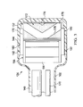
FIG. 3 is a top, cut-away view of the debridement tool ofFIG. 1 ; and -
FIG. 4 is a bottom view of the debridement tool ofFIG. 1 , depicting an illustrative embodiment of a working surface and a working surface port. - In the following detailed description of non-limiting, illustrative embodiments, reference is made to the accompanying drawings that form a part hereof. Other embodiments may be utilized, and logical, structural, mechanical, electrical, and chemical changes may be made without departing from the scope of the appended claims. To avoid detail not necessary to enable those skilled in the art to practice the embodiments described herein, the description may omit certain information known to those skilled in the art. Thus, the following detailed description is non-limiting with the scope of the illustrative embodiments being defined by the appended claims. As used herein, unless otherwise indicated, the use of "or" does not require mutual exclusivity.
- Referring to the drawings,
FIG. 1 depicts an illustrative embodiment of asystem 102 for debriding tissue from atissue site 104 of a patient. Thetissue site 104 may extend through or otherwise involve anepidermis 106, adermis 108, and asubcutaneous tissue 110. Thetissue site 104 may be a sub-surface tissue site as depicted inFIG. 1 that extends below the surface of theepidermis 106. Further, thetissue site 104 may be a surface tissue site (not shown) that predominantly resides on the surface of theepidermis 106, such as, for example, an incision. Thesystem 102 may also be utilized without limitation at other tissue sites. - The
tissue site 104 may be the bodily tissue of any human, animal, or other organism, including bone tissue, adipose tissue, muscle tissue, dermal tissue, vascular tissue, connective tissue, cartilage, tendons, ligaments, or any other tissue. Debriding tissue from thetissue site 104 may include the removal of fluids, such as exudate or ascites, and the removal ofnecrotic tissue 112 from thetissue site 104 in effort to promote the healing ofhealthy tissue 114. - The terms "debride", "debriding", and "debridement" as used herein may refer to the removal of the
necrotic tissue 112 to improve the healing potential of the remaininghealthy tissue 114, but is not limited to removing only necrotic tissue. The term "necrotic tissue" as used herein may refer to dead, damaged, or infected tissue. Although in some embodiments the debridement of necrotic tissue may involve an incision or cut to be made at a tissue site, the disclosed embodiments may also be used to debride necrotic tissue without requiring any such incisions or cuts. - Referring to the illustrative embodiments of
FIG. 1 , thesystem 102 may include atherapy device 120 and adebridement tool 124. Thetherapy device 120 may include a reduced-pressure source 128, apressure sensor 132, and acanister 136. Components of thesystem 102 may be omitted, added, or modified as described herein in other embodiments. Further, components of thesystem 102 may be provided integrally or separate where applicable. For example, the reduced-pressure source 128, thepressure sensor 132, and thecanister 136 may be provided integrally as part of thetherapy device 120 as shown inFIG. 1 , or as separate components. - The reduced-
pressure source 128 may provide reduced pressure to thedebridement tool 124 and thetissue site 104. In some embodiments, thecanister 136 may be in fluid communication between the reduced-pressure source 128 and thedebridement tool 124 for collecting fluids and other matter, such as exudate, dislodged necrotic tissue, and waste, from thetissue site 104. For example, reduced pressure may be communicated to thedebridement tool 124 through thecanister 136, whereby such fluids can be drawn through thedebridement tool 124 and communicated to thecanister 136 by operation of the reduced pressure being applied. Thecanister 136 may be any suitable containment device having a sealed internal volume capable of retaining the fluids and other matter described above. - The reduced-
pressure source 128 maybe any suitable device for providing reduced pressure, such as, for example, a vacuum pump, wall suction, hand pump, or other source. In some embodiments, the reduced-pressure source 128 may be capable of delivering a flow rate between about 5 liters per minute to about 10 liters per minute. In other embodiments, the flow rate may be between about 6 liters per minute to about 8 liters per minute. As an additional example, the reduced-pressure source 128 may be provided as a component of an InfoV.A.C.® therapy unit or a V.A.C. Ulta® therapy unit available from Kinetic Concepts, Inc. of San Antonio, Texas. - As used herein, the term "reduced pressure" may refer to a pressure less than the ambient pressure at a tissue site being treated or debrided. In some embodiments, the reduced pressure may be less than the atmospheric pressure. In some embodiments, the reduced pressure may be less than a hydrostatic pressure at a tissue site. Unless otherwise indicated, values of pressure stated herein are gauge pressures. While the amount and nature of reduced pressure applied to a tissue site may vary according to the application, the reduced pressure may be between about 0 mm Hg to about -500 mm Hg. In some embodiments, the reduced pressure may be between about -75 mm Hg to about -200 mm Hg.
- The reduced pressure delivered may be constant, varied, patterned, or random, and may be delivered continuously or intermittently. Although the terms "vacuum" and "negative pressure" maybe used to describe the pressure applied to the
debridement tool 124 and thetissue site 104, the actual pressure may be more than the pressure normally associated with a complete vacuum. Further, an increase in reduced pressure may correspond to a reduction in pressure (more negative relative to ambient pressure), and a decrease in reduced pressure may correspond to an increase in pressure (less negative relative to ambient pressure). - Referring to
FIGS. 1-4 , thedebridement tool 124 may include ahousing 144, a reduced-pressure lumen 148, adebridement head 152, animpeller 156, and adrive system 160. Thehousing 144 may include aninterior space 162 and a workingsurface 164. The workingsurface 164 may be adapted to face thetissue site 104, and may have a workingsurface port 166 disposed through the workingsurface 164. The workingsurface 164 may be in fluid communication with theinterior space 162 through the workingsurface port 166. Further, the reduced-pressure source 128 may be in fluid communication with the workingsurface 164 through the workingsurface port 166. In some embodiments, ahandle 168 may be coupled to thehousing 144 to provide a user with an ergonomic grip for thedebridement tool 124. Components of thedebridement tool 124 may be coupled to or otherwise associated with thehousing 144 in any suitable manner consistent with the operational parameters described herein. - The
housing 144 of thedebridement tool 124 may comprise a medical-grade polymer, metal, or other suitable material. As non-limiting examples, thehousing 144 may be formed from polyurethane, polyethylene, polyvinyl chloride (PVC), fluorosilicone, ethylenepropylene, ABS, or similar material. In some illustrative, non-limiting embodiments, thehousing 144 may be molded from DEHP-free PVC, ABS or other suitable medical grade polymer. Thehousing 144 maybe formed in any suitable manner such as by molding, casting, machining, or extruding. Further, thehousing 144 may be formed as an integral unit or as individual components. - The reduced-
pressure lumen 148 maybe in fluid communication with the workingsurface 164 through the workingsurface port 166 for communicating reduced pressure. In some embodiments, the reduced-pressure lumen 148 may be in fluid communication with theinterior space 162 through thehandle 168. Further, the reduced-pressure source 128 may be in fluid communication with the reduced-pressure lumen 148 through thecanister 136. - In some embodiments, a
feedback pressure lumen 170 may be in fluid communication with theinterior space 162 of thehousing 144. For example, thefeedback pressure lumen 170 may be in fluid communication with theinterior space 162 through thehandle 168. Further, thefeedback pressure lumen 170 may be fluidly isolated from the reduced-pressure lumen 148 along the length of thehandle 168. In some embodiments, thefeedback pressure lumen 170 may be in fluid communication with thepressure sensor 132. For example, thefeedback pressure lumen 170 may be adapted to communicate reduced pressure, such as a reduced pressure feedback signal, from thedebridement tool 124 and/or thetissue site 104 to thepressure sensor 132. Thus, although in some embodiments thefeedback pressure lumen 170 and the reduced-pressure lumen 148 may be in fluid communication with theinterior space 162, thefeedback pressure lumen 170 and the reduced-pressure lumen 148 may be physically separate from one another. - The
debridement head 152 may be moveable relative to thehousing 144 and may be cylindrical in shape. In some embodiments, thedebridement head 152 may have anexterior surface 172 rotatable about adebridement head axis 174. As shown inFIGS. 2-4 , theexterior surface 172 of thedebridement head 152 may comprise anabrasive portion 176. In some embodiments, theexterior surface 172 of thedebridement head 152 may comprise theabrasive portion 176 and an optionalnon-abrasive portion 178. Thedebridement head 152 may be positioned within theinterior space 162, and at least a portion of theexterior surface 172 of thedebridement head 152 may be adapted to protrude through the workingsurface port 166. In some embodiments, theexterior surface 172 of thedebridement head 152 may be adapted to protrude through the workingsurface port 166 and beyond the workingsurface 164 by adebridement depth 180 between about 0.5 millimeters to about 2.0 millimeters. - Referring to
FIGS. 2-3 , in some embodiments, theexterior surface 172 of thedebridement head 152 may comprise a plurality of theabrasive portions 176 and a plurality of thenon-abrasive portions 178. Theabrasive portions 176 may be positioned between thenon-abrasive portions 178 about a circumference of theexterior surface 172 of thedebridement head 152. Such a configuration alternating theabrasive portions 176 and thenon-abrasive portions 178 may enhance the ability of thedebridement head 152 to rotate in contact with thetissue site 104 without becoming bound against thetissue site 104. Theabrasive portions 176 may comprise any suitable abrasive material such as, for example, a coarse grade sandpaper, a coating of grit, crushed media, or similar material. In some embodiments, theabrasive portions 176 may comprise without limitation protruding polymer bristles, metal wire, fibers, or cutting teeth. Further, a variety of interchangeable debridement heads 152 having different combinations of abrasives as described above may be provided in a kit with thedebridement tool 124. - Continuing with
FIGS. 2-3 , theimpeller 156 may be moveable relative to thehousing 144 and be positioned in fluid communication with the reduced-pressure lumen 148. In some embodiments, theimpeller 156 may include a plurality ofimpeller vanes 184 rotatable about animpeller axis 186. Theimpeller 156 may be adapted to rotate by operation of reduced pressure being applied to theimpeller vanes 184. For example, theimpeller 156 may be positioned within theinterior space 162 and/or in fluid communication with theinterior space 162 in the path of reduced pressure being communicated therethrough. In some embodiments, the reduced-pressure source 128 may be in fluid communication with theimpeller 156 through the reduced-pressure lumen 148. - Referring to
FIGS. 1-3 , thedrive system 160 may be coupled to or between theimpeller 156 and thedebridement head 152. In some embodiments, thedrive system 160 may include animpeller pulley 188, adebridement head pulley 190, and adrive belt 192. Theimpeller pulley 188 may be coupled to theimpeller 156 and be rotatable with theimpeller 156 about theimpeller axis 186. Thedebridement head pulley 190 may be coupled to thedebridement head 152 and be rotatable with thedebridement head 152 about thedebridement head axis 174. Thedrive belt 192 may be positioned about theimpeller pulley 188 and thedebridement head pulley 190 such that thedrive system 160 may be configured to impart movement from theimpeller 156 to thedebridement head 152. AlthoughFIG. 3 depicts thedrive system 160 positioned at each opposing end of thedebridement head axis 174 and theimpeller axis 186, other embodiments may use thedrive system 160 at only one end of thedebridement head axis 174 and theimpeller axis 186. Further, although not explicitly shown in the drawings, thehousing 144 may have, for example, brackets, pins, axles, bearings and other such devices for coupling or associating theimpeller 156, thedebridement head 152, thedrive system 160, and other components of thedebridement tool 124 with thehousing 144 as described herein. - Referring to
FIG. 1 , thedebridement tool 124 may be coupled in fluid communication with thetherapy device 120, or individual components of thetherapy device 120 set forth above. For example, the reduced-pressure lumen 148 of thedebridement tool 124 may be in fluid communication with the reduced-pressure source 128, and thefeedback pressure lumen 170 of thedebridement tool 124 may be in fluid communication with thepressure sensor 132. In some embodiments, the reduced-pressure source 128 maybe in fluid communication with theimpeller 156 and the workingsurface port 166. Further, in some embodiments, the reduced-pressure source 128 may be in fluid communication with theimpeller 156 through the reduced-pressure lumen 148. Even further, in some embodiments, the reduced-pressure source 128 may be in fluid communication with the reduced-pressure lumen 148 through thecanister 136. - Continuing with
FIG. 1 , in some embodiments, amulti-lumen conduit 194 maybe coupled in fluid communication between thedebridement tool 124 and thetherapy device 120. Themulti-lumen conduit 194 may include multiple lumens, such as aprimary lumen 196 and asecondary lumen 198. The reduced-pressure lumen 148 may be coupled in fluid communication with theprimary lumen 196 for providing fluid communication with the reduced-pressure source 128. Further, thefeedback pressure lumen 170 may be coupled in fluid communication with thesecondary lumen 198 for providing fluid communication with thepressure sensor 132. Theprimary lumen 196 may be substantially isolated from fluid communication with thesecondary lumen 198 along the length of themulti-lumen conduit 194. Although shown inFIG. 1 as having a substantially circular cross-section, themulti-lumen conduit 194 may have any shape to suit a particular application. Further, themulti-lumen conduit 194 may comprise, for example, a flexible polymer. Each distal end of themulti-lumen conduit 194 may include aconnector 199 for coupling themulti-lumen conduit 194 in fluid communication between thetherapy device 120 and thedebridement tool 124. - Referring to
FIGS. 1-4 , in an illustrative embodiment of operation, the workingsurface 164 of thedebridement tool 124 may be positioned proximate to or in contact with thenecrotic tissue 112 at thetissue site 104. Theexternal surface 172 of thedebridement head 152 may be positioned in contact with thenecrotic tissue 112, and the workingsurface port 166 may be positioned in fluid communication with thetissue site 104. Reduced pressure may be communicated from the reduced-pressure source 128 to theimpeller 156 of thedebridement tool 124 and to thetissue site 104 through the workingsurface port 166. Reduced pressure may induce fluid flow across theimpeller vanes 184 of theimpeller 156 to impart movement or rotation on theimpeller 156. Rotation of theimpeller 156 and theimpeller pulley 188 coupled to theimpeller 156 may be operable to impart rotation on thedebridement head 152 in a corresponding manner. For example, thedrive belt 192 that may be coupled between theimpeller pulley 188 and thedebridement head pulley 190 may impart rotational movement from theimpeller 156 to thedebridement head 152. Such movement of thedebridement head 152 while being positioned in contact with thenecrotic tissue 112 may operate to debride or otherwise dislodge thenecrotic tissue 112 from thetissue site 104. A saline or water solution may be added at thetissue site 104 to assist with dislodging thenecrotic tissue 112, preventing blockages, and reducing pain for the patient. - Reduced pressure being applied to the
tissue site 104 may extract the dislodgednecrotic tissue 112, fluids, wound exudate, or other waste material from thetissue site 104 without disturbing thehealthy tissue 114 that may surround and/or underlie thenecrotic tissue 112. Further, since theexternal surface 172 of thedebridement head 152 may protrude through the workingsurface port 166, the workingsurface 166 may operate as a guard or guide for the debridement operation. For example, the workingsurface 166 may substantially preclude thedebridement head 152 from entering or engaging thetissue site 104 at a depth beyond theprescribed debridement depth 180, which may damage or disrupt thehealthy tissue 114. In this manner, thedebridement tool 124 according to this disclosure may provide enhanced control for the user and safety for the patient, which may also reduce the amount oftraining required for use of thedebridement tool 124. Further, since thedebridement tool 124 is mechanical in operation by virtue of reduced pressure incident on theimpeller 156, thedebridement tool 124 may provide the user with a low cost, disposable option for performing debridement. - Further, the
therapy device 120 may be configured to control the amount of reduced pressure from the reduced-pressure source 128 being applied to thedebridement tool 124 and thetissue site 104 according to a user input and/or reduced-pressure feedback signal. For example, the reduced-pressure feedback signal may be communicated from thefeedback pressure lumen 170 of thedebridement tool 124 to thepressure sensor 132. Thetherapy device 120 and thesystem 102 may include additional control circuitry, processors, and sensors as necessary for processing and monitoring the reduced pressure being applied to thedebridement tool 124 and thetissue site 104. For example, a processor (not shown) including a control algorithm may be associated with thepressure sensor 132 in any suitable manner for controlling the output from the reduced-pressure source 128 according to the reduced-pressure feedback signal and/or user input. - In some embodiments, a feedback reduced pressure less than about -5 mm Hg and decreasing to about 0 mm Hg may be measured at the working
surface 164 and/or thetissue site 104 through thefeedback pressure lumen 170 in normal operation of thesystem 102. If the reduced pressure output measured at the reduced-pressure source 128 reaches a maximum reduced pressure, such as between about -300 mm Hg to about -400 mm Hg, while the feedback reduced pressure is less than about -5mm Hg, or about 0 mm Hg, then a debridement tubing blockage alarm may be reported. The debridement tubing blockage alarm may indicate a blockage in the reduced-pressure lumen 148. In other embodiments, the maximum reduced pressure may be between about -300 mm Hg to about -380 mm Hg. - In some embodiments, if the feedback reduced pressure is between about -5 mm Hg to about -100 mm Hg, then a partial head-blockage alarm may be reported. The partial head-blockage alarm may indicate a partial blockage in the
debridement tool 124, such as, for example, at or among theinterior space 162 of thehousing 144, thedebridement head 152, the workingsurface 164, or the workingsurface port 166. The partial head-blockage alarm may serve as an alert to the user that thedebridement tool 124 requires cleaning or replacement, but thesystem 102 may otherwise remain operable during a partial head-blockage alarm. - In some embodiments, if the feedback reduced pressure is greater than about -100 mm Hg, then the reduced-
pressure source 128 may increase the reduced pressure output to the maximum reduced pressure set forth above for a set time period to remediate the blockage. If the feedback reduced pressure does not decrease or otherwise move toward normal operational levels, such as about 0 mm Hg, after the set time period, then a full head blockage alarm may be reported and thesystem 102 may shut down. - Based on the above operational and control parameters, the
system 102 can detect blockages in thedebridement tool 124 that may prevent components of thedebridement tool 124 from rotating, such as thedebridement head 152. Further, thesystem 102 maybe configured to detect if thedebridement tool 124 has become sealed against thetissue site 104, restricting flow and causing an increase in reduced pressure at thetissue site 104. Thesystem 102 may take the steps described above to alert a user and shut down the reduced-pressure source 128 as necessary. - In some illustrative embodiments, a method for debriding the
tissue site 104 may include providing thedebridement tool 124. In some embodiments, thedebridement tool 124 may include thehousing 144, thedebridement head 152, theimpeller 156, and thedrive system 160. Thehousing 144 may include theinterior space 162 and the workingsurface 164. The workingsurface port 166 may be disposed through the workingsurface 164 and in fluid communication with theinterior space 162. Thedebridement head 152 may be moveable relative to thehousing 144, and thedrive system 160 may be coupled between theimpeller 156 and thedebridement head 152. - The method may further include communicating reduced pressure to the working
surface 164 and communicating reduced pressure to theimpeller 156. In some embodiments, the reduced pressure may be communicated to the workingsurface 164 through the workingsurface port 166. In other embodiments, the reduced pressure may be communicated to the workingsurface 164 and/or thetissue site 104, for example, by a lumen or conduit (not shown) that may be separate from, integral with, or attached to thedebridement tool 124. Theimpeller 156 may be configured to rotate by operation of reduced pressure being applied to theimpeller 156. Further, the method may include moving thedebridement head 152 relative to thehousing 144 with thedrive system 160, and positioning thedebridement head 152 in contact with thetissue site 104. In some embodiments, the workingsurface 164 may be positioned in contact with thetissue site 104 along with thedebridement head 152. Thedrive system 160 may be operable to impart movement from theimpeller 156 to thedebridement head 152. - In some embodiments, the method may further include dislodging the
necrotic tissue 112 from thetissue site 104 by moving thedebridement head 152 relative to thetissue site 104 when thedebridement head 152 is in contact with thetissue site 104 and reduced pressure is being communicated to theimpeller 156. In some embodiments, the method may further include removing dislodgednecrotic tissue 112 from thetissue site 104 by operation of reduced pressure being communicated to the workingsurface 164. In some embodiments, the method may further include communicating dislodgednecrotic tissue 112 into thecanister 136 by operation of the reduced pressure being applied to the workingsurface 164. - In some embodiments, the method may further include comparing a reduced pressure output being communicated to the working
surface 164 with a feedback reduced pressure measured within theinterior space 162 of thehousing 144. In some embodiments, the method may further include signaling a debridement tubing blockage alarm if the reduced pressure output is at a maximum reduced pressure and the feedback reduced pressure is substantially zero, or between about 0 mm Hg to about -5 mm Hg. In some embodiments, the method may further include signaling a partial head-blockage alarm if the feedback reduced pressure is between about -5 mm Hg to about -100 mm Hg. - In some embodiments, the method may further include: increasing the reduced pressure output to a maximum pressure for a set time period if the feedback reduced pressure is greater than -100 mm Hg; signaling a full head blockage alarm if the feedback reduced pressure is greater than -100 mm Hg after the set time period; and shutting off the reduced pressure output if the feedback reduced pressure is greater than -100 mm Hg after the set time period.
- Although this specification discloses advantages in the context of certain illustrative, non-limiting embodiments, various changes, substitutions, permutations, and alterations may be made without departing from the scope of the appended claims. Further, any feature described in connection with any one embodiment may also be applicable to any other embodiment.
Claims (15)
- A debridement tool for debriding tissue from a tissue site, comprising:a housing (164) comprising an interior space (162);a reduced-pressure lumen (148) adapted to communicate reduced pressure (162);a debridement head (152) moveable relative to the housing (164);an impeller (156) moveable relative to the housing (164) and positioned in fluid communication with the reduced-pressure lumen (148); anda drive system (160) coupled between the impeller (156) and the debridement head (152), the drive system (160) being configured to impart movement from the impeller (156) to the debridement head (152).
- The debridement tool of claim 1, further comprising a working surface (164) adapted to face the tissue site, and a working surface port (166) disposed through the working surface (164).
- The debridement tool of claim 1 or claim 2, wherein the reduced-pressure lumen (148) is in fluid communication with the interior space (162).
- The debridement tool of any preceding claim, further comprising a feedback pressure lumen (170) adapted to communicate reduced pressure and being positioned in fluid communication with the interior space (162).
- The debridement tool of any preceding claim, wherein the debridement head (152) comprises a debridement head axis (174) and an exterior surface (172) rotatable about the debridement head axis (174), the exterior surface (172) of the debridement head (152) comprising an abrasive portion .
- The debridement tool of claim 5, wherein the exterior surface of the debridement head is cylindrical.
- The debridement tool of claim 5 or claim 6, wherein the exterior surface of the debridement head further comprises a non-abrasive portion (176).
- The debridement tool of any of claims 5 to 7, wherein the abrasive portion (176) is a plurality of abrasive portions, the exterior surface (172) of the debridement head (152) further comprising a plurality of non-abrasive portions (178), the abrasive portions (176) being positioned between the non-abrasive portions (178) about the exterior surface (172) of the debridement head (152).
- The debridement tool of any of claims 5 to 7, wherein the abrasive portion (176)_comprises at least one of at least one cutting tooth, a coating of grit; protruding bristles; and protruding wires.
- The debridement tool of claim 1, wherein the housing (164) further comprises a working surface (164) adapted to face the tissue site, and a working surface port (166) disposed through the working surface (164), at least a portion of the exterior surface (172) of the debridement head (152) being adapted to protrude through the working surface port (166).
- The debridement tool of claim 10, wherein the exterior surface (172)_of the debridement head (152) is adapted to protrude through the working surface port (166) and beyond the working surface (164) between about 0.5 millimeters to about 2.0 millimeters.
- The debridement tool of any preceding claim, wherein the impeller (156) comprises an impeller axis (186) and a plurality of impeller vanes (184) rotatable about the impeller axis (186).
- The debridement tool of any preceding claim, wherein the drive system (160 comprises an impeller pulley (168), a debridement head pulley (190), and a drive belt (192), the impeller pulley (168) being coupled to the impeller (156) and moveable with the impeller (156), the debridement head pulley (190) being coupled to the debridement head (152) and moveable with the debridement head (152), the drive belt (192) being positioned about the impeller pulley (168) and the debridement head pulley (190).
- A system for debriding tissue from a tissue site, comprising:a debridement tool according to any preceding claim, anda reduced-pressure source (128) in fluid communication with the impeller (156) through the reduced-pressure lumen (148).
- The system of claim 14 when dependent on claim 4, further comprising a pressure sensor in fluid communication with the feedback pressure lumen.
Applications Claiming Priority (3)
| Application Number | Priority Date | Filing Date | Title |
|---|---|---|---|
| US201462007775P | 2014-06-04 | 2014-06-04 | |
| US201462007790P | 2014-06-04 | 2014-06-04 | |
| US14/689,842 US10335184B2 (en) | 2014-06-04 | 2015-04-17 | Negative pressure tissue debridement devices, systems, and methods |
Publications (2)
| Publication Number | Publication Date |
|---|---|
| EP2952147A1 true EP2952147A1 (en) | 2015-12-09 |
| EP2952147B1 EP2952147B1 (en) | 2017-03-08 |
Family
ID=53757955
Family Applications (1)
| Application Number | Title | Priority Date | Filing Date |
|---|---|---|---|
| EP15170632.2A Active EP2952147B1 (en) | 2014-06-04 | 2015-06-04 | Negative pressure tissue debridement devices and systems |
Country Status (2)
| Country | Link |
|---|---|
| US (2) | US10335184B2 (en) |
| EP (1) | EP2952147B1 (en) |
Cited By (1)
| Publication number | Priority date | Publication date | Assignee | Title |
|---|---|---|---|---|
| CN111867534A (en) * | 2018-03-13 | 2020-10-30 | Bsn医疗有限公司 | Mechanical wound cleaning device |
Families Citing this family (4)
| Publication number | Priority date | Publication date | Assignee | Title |
|---|---|---|---|---|
| USD825756S1 (en) * | 2016-12-23 | 2018-08-14 | Derek T. Denton | Manual debridement implement |
| TWD201425S (en) * | 2019-02-26 | 2019-12-11 | 威視國際有限公司 | foot grinder |
| US11707292B2 (en) | 2021-02-01 | 2023-07-25 | Mazor Robotics Ltd. | Disc cleaning surgical tool |
| CN115531114B (en) * | 2022-09-20 | 2025-01-24 | 中国人民解放军空军军医大学 | A debridement vehicle |
Citations (8)
| Publication number | Priority date | Publication date | Assignee | Title |
|---|---|---|---|---|
| US2049874A (en) * | 1933-08-21 | 1936-08-04 | Miami Abrasive Products Inc | Slotted abrasive wheel |
| US6185781B1 (en) * | 1999-06-24 | 2001-02-13 | The Hoover Company | Hand scrub tool with interchangeable scrub drives |
| US6500183B1 (en) * | 1999-11-12 | 2002-12-31 | Altair Instruments, Inc | Microdermabrasion device |
| WO2004002339A1 (en) * | 2002-06-27 | 2004-01-08 | Cipolla Maria Luisa | Apparatus for removing corns and callosities from the skin |
| US20040010268A1 (en) * | 2002-07-11 | 2004-01-15 | Gabehart Michael A. | Dermabrasion/microdermabrasion apparatus |
| WO2007080020A1 (en) * | 2005-12-29 | 2007-07-19 | Robert Bosch Gmbh | Portable power tool having a turbine unit |
| EP1815942A1 (en) * | 2006-02-02 | 2007-08-08 | M.B.H. Developpement | Transportable equipment intended for grinding, sanding, surfacing, including a device that works by depression |
| DE202011104490U1 (en) * | 2010-09-21 | 2011-11-16 | Renè Merz | Device for removing dead skin structures and skin particles |
Family Cites Families (130)
| Publication number | Priority date | Publication date | Assignee | Title |
|---|---|---|---|---|
| US500415A (en) * | 1893-06-27 | Lewis p | ||
| US1355846A (en) | 1920-02-06 | 1920-10-19 | David A Rannells | Medical appliance |
| US2547758A (en) | 1949-01-05 | 1951-04-03 | Wilmer B Keeling | Instrument for treating the male urethra |
| US2632443A (en) | 1949-04-18 | 1953-03-24 | Eleanor P Lesher | Surgical dressing |
| GB692578A (en) | 1949-09-13 | 1953-06-10 | Minnesota Mining & Mfg | Improvements in or relating to drape sheets for surgical use |
| US2682873A (en) | 1952-07-30 | 1954-07-06 | Johnson & Johnson | General purpose protective dressing |
| US2812155A (en) * | 1952-11-18 | 1957-11-05 | Harold B Pearson | Venetian blind cleaner |
| NL189176B (en) | 1956-07-13 | 1900-01-01 | Hisamitsu Pharmaceutical Co | PLASTER BASED ON A SYNTHETIC RUBBER. |
| US2969057A (en) | 1957-11-04 | 1961-01-24 | Brady Co W H | Nematodic swab |
| US3066672A (en) | 1960-09-27 | 1962-12-04 | Jr William H Crosby | Method and apparatus for serial sampling of intestinal juice |
| US3367332A (en) | 1965-08-27 | 1968-02-06 | Gen Electric | Product and process for establishing a sterile area of skin |
| US3520300A (en) | 1967-03-15 | 1970-07-14 | Amp Inc | Surgical sponge and suction device |
| US3568675A (en) | 1968-08-30 | 1971-03-09 | Clyde B Harvey | Fistula and penetrating wound dressing |
| US3682180A (en) | 1970-06-08 | 1972-08-08 | Coilform Co Inc | Drain clip for surgical drain |
| BE789293Q (en) | 1970-12-07 | 1973-01-15 | Parke Davis & Co | MEDICO-SURGICAL DRESSING FOR BURNS AND SIMILAR LESIONS |
| US3826254A (en) | 1973-02-26 | 1974-07-30 | Verco Ind | Needle or catheter retaining appliance |
| DE2527706A1 (en) | 1975-06-21 | 1976-12-30 | Hanfried Dr Med Weigand | DEVICE FOR THE INTRODUCTION OF CONTRAST AGENTS INTO AN ARTIFICIAL INTESTINAL OUTLET |
| DE2640413C3 (en) | 1976-09-08 | 1980-03-27 | Richard Wolf Gmbh, 7134 Knittlingen | Catheter monitor |
| NL7710909A (en) | 1976-10-08 | 1978-04-11 | Smith & Nephew | COMPOSITE STRAPS. |
| GB1562244A (en) | 1976-11-11 | 1980-03-05 | Lock P M | Wound dressing materials |
| US4080970A (en) | 1976-11-17 | 1978-03-28 | Miller Thomas J | Post-operative combination dressing and internal drain tube with external shield and tube connector |
| US4139004A (en) | 1977-02-17 | 1979-02-13 | Gonzalez Jr Harry | Bandage apparatus for treating burns |
| US4184510A (en) | 1977-03-15 | 1980-01-22 | Fibra-Sonics, Inc. | Valued device for controlling vacuum in surgery |
| US4165748A (en) | 1977-11-07 | 1979-08-28 | Johnson Melissa C | Catheter tube holder |
| US4256109A (en) | 1978-07-10 | 1981-03-17 | Nichols Robert L | Shut off valve for medical suction apparatus |
| SE414994B (en) | 1978-11-28 | 1980-09-01 | Landstingens Inkopscentral | VENKATETERFORBAND |
| WO1980001139A1 (en) | 1978-12-06 | 1980-06-12 | Svedman Paul | Device for treating tissues,for example skin |
| US4266545A (en) | 1979-04-06 | 1981-05-12 | Moss James P | Portable suction device for collecting fluids from a closed wound |
| US4284079A (en) | 1979-06-28 | 1981-08-18 | Adair Edwin Lloyd | Method for applying a male incontinence device |
| US4261363A (en) | 1979-11-09 | 1981-04-14 | C. R. Bard, Inc. | Retention clips for body fluid drains |
| US4569348A (en) | 1980-02-22 | 1986-02-11 | Velcro Usa Inc. | Catheter tube holder strap |
| ATE14835T1 (en) | 1980-03-11 | 1985-08-15 | Schmid Eduard | SKIN GRAFT PRESSURE BANDAGE. |
| US4297995A (en) | 1980-06-03 | 1981-11-03 | Key Pharmaceuticals, Inc. | Bandage containing attachment post |
| US4294595A (en) * | 1980-07-18 | 1981-10-13 | Electrolux Corporation | Vacuum cleaner including automatic shutoff device |
| US4333468A (en) | 1980-08-18 | 1982-06-08 | Geist Robert W | Mesentery tube holder apparatus |
| US4465485A (en) | 1981-03-06 | 1984-08-14 | Becton, Dickinson And Company | Suction canister with unitary shut-off valve and filter features |
| US4392853A (en) | 1981-03-16 | 1983-07-12 | Rudolph Muto | Sterile assembly for protecting and fastening an indwelling device |
| US4373519A (en) | 1981-06-26 | 1983-02-15 | Minnesota Mining And Manufacturing Company | Composite wound dressing |
| US4392858A (en) | 1981-07-16 | 1983-07-12 | Sherwood Medical Company | Wound drainage device |
| US4419097A (en) | 1981-07-31 | 1983-12-06 | Rexar Industries, Inc. | Attachment for catheter tube |
| AU550575B2 (en) | 1981-08-07 | 1986-03-27 | Richard Christian Wright | Wound drainage device |
| SE429197B (en) | 1981-10-14 | 1983-08-22 | Frese Nielsen | SAR TREATMENT DEVICE |
| DE3146266A1 (en) | 1981-11-21 | 1983-06-01 | B. Braun Melsungen Ag, 3508 Melsungen | COMBINED DEVICE FOR A MEDICAL SUCTION DRAINAGE |
| US4551139A (en) | 1982-02-08 | 1985-11-05 | Marion Laboratories, Inc. | Method and apparatus for burn wound treatment |
| US4475909A (en) | 1982-05-06 | 1984-10-09 | Eisenberg Melvin I | Male urinary device and method for applying the device |
| EP0100148B1 (en) | 1982-07-06 | 1986-01-08 | Dow Corning Limited | Medical-surgical dressing and a process for the production thereof |
| NZ206837A (en) | 1983-01-27 | 1986-08-08 | Johnson & Johnson Prod Inc | Thin film adhesive dressing:backing material in three sections |
| US4548202A (en) | 1983-06-20 | 1985-10-22 | Ethicon, Inc. | Mesh tissue fasteners |
| US4540412A (en) | 1983-07-14 | 1985-09-10 | The Kendall Company | Device for moist heat therapy |
| US4543100A (en) | 1983-11-01 | 1985-09-24 | Brodsky Stuart A | Catheter and drain tube retainer |
| US4525374A (en) | 1984-02-27 | 1985-06-25 | Manresa, Inc. | Treating hydrophobic filters to render them hydrophilic |
| CA1286177C (en) | 1984-05-03 | 1991-07-16 | Smith And Nephew Associated Companies Plc | Adhesive wound dressing |
| US4897081A (en) | 1984-05-25 | 1990-01-30 | Thermedics Inc. | Percutaneous access device |
| US5215522A (en) | 1984-07-23 | 1993-06-01 | Ballard Medical Products | Single use medical aspirating device and method |
| GB8419745D0 (en) | 1984-08-02 | 1984-09-05 | Smith & Nephew Ass | Wound dressing |
| US4872450A (en) | 1984-08-17 | 1989-10-10 | Austad Eric D | Wound dressing and method of forming same |
| US4655754A (en) | 1984-11-09 | 1987-04-07 | Stryker Corporation | Vacuum wound drainage system and lipids baffle therefor |
| US4826494A (en) | 1984-11-09 | 1989-05-02 | Stryker Corporation | Vacuum wound drainage system |
| US4605399A (en) | 1984-12-04 | 1986-08-12 | Complex, Inc. | Transdermal infusion device |
| US5037397A (en) | 1985-05-03 | 1991-08-06 | Medical Distributors, Inc. | Universal clamp |
| US4640688A (en) | 1985-08-23 | 1987-02-03 | Mentor Corporation | Urine collection catheter |
| US4710165A (en) | 1985-09-16 | 1987-12-01 | Mcneil Charles B | Wearable, variable rate suction/collection device |
| US4758220A (en) | 1985-09-26 | 1988-07-19 | Alcon Laboratories, Inc. | Surgical cassette proximity sensing and latching apparatus |
| US4733659A (en) | 1986-01-17 | 1988-03-29 | Seton Company | Foam bandage |
| WO1987004626A1 (en) | 1986-01-31 | 1987-08-13 | Osmond, Roger, L., W. | Suction system for wound and gastro-intestinal drainage |
| US4838883A (en) | 1986-03-07 | 1989-06-13 | Nissho Corporation | Urine-collecting device |
| JPS62281965A (en) | 1986-05-29 | 1987-12-07 | テルモ株式会社 | Catheter and catheter fixing member |
| GB8621884D0 (en) | 1986-09-11 | 1986-10-15 | Bard Ltd | Catheter applicator |
| GB2195255B (en) | 1986-09-30 | 1991-05-01 | Vacutec Uk Limited | Apparatus for vacuum treatment of an epidermal surface |
| US4743232A (en) | 1986-10-06 | 1988-05-10 | The Clinipad Corporation | Package assembly for plastic film bandage |
| DE3634569A1 (en) | 1986-10-10 | 1988-04-21 | Sachse Hans E | CONDOM CATHETER, A URINE TUBE CATHETER FOR PREVENTING RISING INFECTIONS |
| JPS63135179A (en) | 1986-11-26 | 1988-06-07 | 立花 俊郎 | Subcataneous drug administration set |
| GB8628564D0 (en) | 1986-11-28 | 1987-01-07 | Smiths Industries Plc | Anti-foaming agent suction apparatus |
| GB8706116D0 (en) | 1987-03-14 | 1987-04-15 | Smith & Nephew Ass | Adhesive dressings |
| US4787888A (en) | 1987-06-01 | 1988-11-29 | University Of Connecticut | Disposable piezoelectric polymer bandage for percutaneous delivery of drugs and method for such percutaneous delivery (a) |
| US4863449A (en) | 1987-07-06 | 1989-09-05 | Hollister Incorporated | Adhesive-lined elastic condom cathether |
| US5176663A (en) | 1987-12-02 | 1993-01-05 | Pal Svedman | Dressing having pad with compressibility limiting elements |
| US4906240A (en) | 1988-02-01 | 1990-03-06 | Matrix Medica, Inc. | Adhesive-faced porous absorbent sheet and method of making same |
| US4985019A (en) | 1988-03-11 | 1991-01-15 | Michelson Gary K | X-ray marker |
| GB8812803D0 (en) | 1988-05-28 | 1988-06-29 | Smiths Industries Plc | Medico-surgical containers |
| US4919654A (en) | 1988-08-03 | 1990-04-24 | Kalt Medical Corporation | IV clamp with membrane |
| US5000741A (en) | 1988-08-22 | 1991-03-19 | Kalt Medical Corporation | Transparent tracheostomy tube dressing |
| DE69017479T2 (en) | 1989-01-16 | 1995-07-13 | Roussel Uclaf | Azabicyclohepten derivatives and their salts, processes for their preparation, their use as medicaments and preparations containing them. |
| GB8906100D0 (en) | 1989-03-16 | 1989-04-26 | Smith & Nephew | Laminates |
| US5100396A (en) | 1989-04-03 | 1992-03-31 | Zamierowski David S | Fluidic connection system and method |
| US5527293A (en) | 1989-04-03 | 1996-06-18 | Kinetic Concepts, Inc. | Fastening system and method |
| US4969880A (en) | 1989-04-03 | 1990-11-13 | Zamierowski David S | Wound dressing and treatment method |
| US5261893A (en) | 1989-04-03 | 1993-11-16 | Zamierowski David S | Fastening system and method |
| JP2719671B2 (en) | 1989-07-11 | 1998-02-25 | 日本ゼオン株式会社 | Wound dressing |
| US5358494A (en) | 1989-07-11 | 1994-10-25 | Svedman Paul | Irrigation dressing |
| US5232453A (en) | 1989-07-14 | 1993-08-03 | E. R. Squibb & Sons, Inc. | Catheter holder |
| GB2235877A (en) | 1989-09-18 | 1991-03-20 | Antonio Talluri | Closed wound suction apparatus |
| US5134994A (en) | 1990-02-12 | 1992-08-04 | Say Sam L | Field aspirator in a soft pack with externally mounted container |
| US5092858A (en) | 1990-03-20 | 1992-03-03 | Becton, Dickinson And Company | Liquid gelling agent distributor device |
| US5149331A (en) | 1991-05-03 | 1992-09-22 | Ariel Ferdman | Method and device for wound closure |
| US5278100A (en) | 1991-11-08 | 1994-01-11 | Micron Technology, Inc. | Chemical vapor deposition technique for depositing titanium silicide on semiconductor wafers |
| US5645081A (en) | 1991-11-14 | 1997-07-08 | Wake Forest University | Method of treating tissue damage and apparatus for same |
| US5636643A (en) | 1991-11-14 | 1997-06-10 | Wake Forest University | Wound treatment employing reduced pressure |
| US5279550A (en) | 1991-12-19 | 1994-01-18 | Gish Biomedical, Inc. | Orthopedic autotransfusion system |
| US5167613A (en) | 1992-03-23 | 1992-12-01 | The Kendall Company | Composite vented wound dressing |
| FR2690617B1 (en) | 1992-04-29 | 1994-06-24 | Cbh Textile | TRANSPARENT ADHESIVE DRESSING. |
| US5388302A (en) * | 1993-01-08 | 1995-02-14 | Black & Decker Inc. | Vacuum cleaner housing and airflow chamber |
| DE4306478A1 (en) | 1993-03-02 | 1994-09-08 | Wolfgang Dr Wagner | Drainage device, in particular pleural drainage device, and drainage method |
| US5342376A (en) | 1993-05-03 | 1994-08-30 | Dermagraphics, Inc. | Inserting device for a barbed tissue connector |
| US6241747B1 (en) | 1993-05-03 | 2001-06-05 | Quill Medical, Inc. | Barbed Bodily tissue connector |
| US5344415A (en) | 1993-06-15 | 1994-09-06 | Deroyal Industries, Inc. | Sterile system for dressing vascular access site |
| US5437651A (en) | 1993-09-01 | 1995-08-01 | Research Medical, Inc. | Medical suction apparatus |
| US5549584A (en) | 1994-02-14 | 1996-08-27 | The Kendall Company | Apparatus for removing fluid from a wound |
| US5607388A (en) | 1994-06-16 | 1997-03-04 | Hercules Incorporated | Multi-purpose wound dressing |
| US5556375A (en) | 1994-06-16 | 1996-09-17 | Hercules Incorporated | Wound dressing having a fenestrated base layer |
| US5664270A (en) | 1994-07-19 | 1997-09-09 | Kinetic Concepts, Inc. | Patient interface system |
| DK1219311T3 (en) | 1994-08-22 | 2004-08-30 | Kci Licensing Inc | Container |
| DE29504378U1 (en) | 1995-03-15 | 1995-09-14 | MTG Medizinisch, technische Gerätebau GmbH, 66299 Friedrichsthal | Electronically controlled low-vacuum pump for chest and wound drainage |
| GB9523253D0 (en) | 1995-11-14 | 1996-01-17 | Mediscus Prod Ltd | Portable wound treatment apparatus |
| US6135116A (en) | 1997-07-28 | 2000-10-24 | Kci Licensing, Inc. | Therapeutic method for treating ulcers |
| GB9719520D0 (en) | 1997-09-12 | 1997-11-19 | Kci Medical Ltd | Surgical drape and suction heads for wound treatment |
| AU755496B2 (en) | 1997-09-12 | 2002-12-12 | Kci Licensing, Inc. | Surgical drape and suction head for wound treatment |
| US6071267A (en) | 1998-02-06 | 2000-06-06 | Kinetic Concepts, Inc. | Medical patient fluid management interface system and method |
| US6488643B1 (en) | 1998-10-08 | 2002-12-03 | Kci Licensing, Inc. | Wound healing foot wrap |
| US6287316B1 (en) | 1999-03-26 | 2001-09-11 | Ethicon, Inc. | Knitted surgical mesh |
| US6856821B2 (en) | 2000-05-26 | 2005-02-15 | Kci Licensing, Inc. | System for combined transcutaneous blood gas monitoring and vacuum assisted wound closure |
| US7799004B2 (en) | 2001-03-05 | 2010-09-21 | Kci Licensing, Inc. | Negative pressure wound treatment apparatus and infection identification system and method |
| US6991643B2 (en) | 2000-12-20 | 2006-01-31 | Usgi Medical Inc. | Multi-barbed device for retaining tissue in apposition and methods of use |
| WO2001062328A1 (en) | 2000-02-24 | 2001-08-30 | Venetec International, Inc. | Universal catheter anchoring system |
| DE10042665C5 (en) * | 2000-08-31 | 2010-06-24 | Düpro AG | Vacuum cleaning tool with a discharge ramp |
| US6471712B2 (en) * | 2000-10-05 | 2002-10-29 | Steven A. Burres | Dermabrasion and skin care apparatus |
| US6540705B2 (en) | 2001-02-22 | 2003-04-01 | Core Products International, Inc. | Ankle brace providing upper and lower ankle adjustment |
| US20050148910A1 (en) * | 2003-12-24 | 2005-07-07 | Gregory Skover | Apparatus having a skin-contactable element containing an agent |
| US20070010828A1 (en) * | 2005-06-23 | 2007-01-11 | Michael Eknoian | Material for mechanical skin resurfacing techniques |
| US9801513B2 (en) * | 2011-11-24 | 2017-10-31 | Omachron Intellectual Property Inc. | Turbo brush |
-
2015
- 2015-04-17 US US14/689,842 patent/US10335184B2/en active Active
- 2015-06-04 EP EP15170632.2A patent/EP2952147B1/en active Active
-
2019
- 2019-05-17 US US16/415,691 patent/US20190269432A1/en not_active Abandoned
Patent Citations (8)
| Publication number | Priority date | Publication date | Assignee | Title |
|---|---|---|---|---|
| US2049874A (en) * | 1933-08-21 | 1936-08-04 | Miami Abrasive Products Inc | Slotted abrasive wheel |
| US6185781B1 (en) * | 1999-06-24 | 2001-02-13 | The Hoover Company | Hand scrub tool with interchangeable scrub drives |
| US6500183B1 (en) * | 1999-11-12 | 2002-12-31 | Altair Instruments, Inc | Microdermabrasion device |
| WO2004002339A1 (en) * | 2002-06-27 | 2004-01-08 | Cipolla Maria Luisa | Apparatus for removing corns and callosities from the skin |
| US20040010268A1 (en) * | 2002-07-11 | 2004-01-15 | Gabehart Michael A. | Dermabrasion/microdermabrasion apparatus |
| WO2007080020A1 (en) * | 2005-12-29 | 2007-07-19 | Robert Bosch Gmbh | Portable power tool having a turbine unit |
| EP1815942A1 (en) * | 2006-02-02 | 2007-08-08 | M.B.H. Developpement | Transportable equipment intended for grinding, sanding, surfacing, including a device that works by depression |
| DE202011104490U1 (en) * | 2010-09-21 | 2011-11-16 | Renè Merz | Device for removing dead skin structures and skin particles |
Cited By (2)
| Publication number | Priority date | Publication date | Assignee | Title |
|---|---|---|---|---|
| CN111867534A (en) * | 2018-03-13 | 2020-10-30 | Bsn医疗有限公司 | Mechanical wound cleaning device |
| CN111867534B (en) * | 2018-03-13 | 2022-06-03 | Bsn医疗有限公司 | Mechanical wound cleaning device |
Also Published As
| Publication number | Publication date |
|---|---|
| US10335184B2 (en) | 2019-07-02 |
| US20190269432A1 (en) | 2019-09-05 |
| US20150351785A1 (en) | 2015-12-10 |
| EP2952147B1 (en) | 2017-03-08 |
Similar Documents
| Publication | Publication Date | Title |
|---|---|---|
| US20190269432A1 (en) | Negative Pressure Tissue Debridement Devices, Systems, And Methods | |
| US11490911B2 (en) | Catheter assembly for blood clot removal | |
| US4735605A (en) | Lipectomy device having round cutting edges | |
| US11931058B2 (en) | Atherectomy motor control system with tactile feedback | |
| JP6854353B2 (en) | Atherectomy medical device | |
| US4792327A (en) | Lipectomy cannula | |
| AU2007303132B2 (en) | Interventional catheters | |
| US20230047964A1 (en) | Atherectomy motor control system | |
| US11090079B2 (en) | Atherectomy motor control system with haptic feedback | |
| US20170143882A1 (en) | Suction device and dressing | |
| JP2013530774A5 (en) | ||
| JP2018504190A (en) | System and method for administering decompression therapy | |
| US20220339342A1 (en) | Systems, methods and handheld pulsatile aspiration and injection devices | |
| US11446049B2 (en) | Wound cleaning tool with fluid delivery and removal capabilities | |
| US12053193B2 (en) | Aspiration pump for removal of fluids, blood clots and other materials from human body | |
| CN211356991U (en) | Negative pressure drainage and cleaning system for suture-free closed skin wound | |
| US20210212715A1 (en) | Water jet surgical device | |
| US20260137857A1 (en) | System, devices and methods for removing a hematoma from a body space | |
| KR200306712Y1 (en) | The device for peeling a thin skin | |
| RO126083B1 (en) | Equipment for controlled cerebral ventricular active lavage | |
| HK1135302B (en) | Interventional catheters |
Legal Events
| Date | Code | Title | Description |
|---|---|---|---|
| PUAI | Public reference made under article 153(3) epc to a published international application that has entered the european phase |
Free format text: ORIGINAL CODE: 0009012 |
|
| AK | Designated contracting states |
Kind code of ref document: A1 Designated state(s): AL AT BE BG CH CY CZ DE DK EE ES FI FR GB GR HR HU IE IS IT LI LT LU LV MC MK MT NL NO PL PT RO RS SE SI SK SM TR |
|
| AX | Request for extension of the european patent |
Extension state: BA ME |
|
| 17P | Request for examination filed |
Effective date: 20160429 |
|
| RBV | Designated contracting states (corrected) |
Designated state(s): AL AT BE BG CH CY CZ DE DK EE ES FI FR GB GR HR HU IE IS IT LI LT LU LV MC MK MT NL NO PL PT RO RS SE SI SK SM TR |
|
| GRAP | Despatch of communication of intention to grant a patent |
Free format text: ORIGINAL CODE: EPIDOSNIGR1 |
|
| INTG | Intention to grant announced |
Effective date: 20161005 |
|
| RAP1 | Party data changed (applicant data changed or rights of an application transferred) |
Owner name: KCI LICENSING, INC. |
|
| RAP1 | Party data changed (applicant data changed or rights of an application transferred) |
Owner name: KCI LICENSING, INC. |
|
| GRAS | Grant fee paid |
Free format text: ORIGINAL CODE: EPIDOSNIGR3 |
|
| GRAA | (expected) grant |
Free format text: ORIGINAL CODE: 0009210 |
|
| AK | Designated contracting states |
Kind code of ref document: B1 Designated state(s): AL AT BE BG CH CY CZ DE DK EE ES FI FR GB GR HR HU IE IS IT LI LT LU LV MC MK MT NL NO PL PT RO RS SE SI SK SM TR |
|
| REG | Reference to a national code |
Ref country code: GB Ref legal event code: FG4D |
|
| REG | Reference to a national code |
Ref country code: CH Ref legal event code: EP Ref country code: AT Ref legal event code: REF Ref document number: 872815 Country of ref document: AT Kind code of ref document: T Effective date: 20170315 |
|
| REG | Reference to a national code |
Ref country code: IE Ref legal event code: FG4D |
|
| REG | Reference to a national code |
Ref country code: DE Ref legal event code: R096 Ref document number: 602015001722 Country of ref document: DE |
|
| REG | Reference to a national code |
Ref country code: LT Ref legal event code: MG4D |
|
| REG | Reference to a national code |
Ref country code: NL Ref legal event code: MP Effective date: 20170308 |
|
| PG25 | Lapsed in a contracting state [announced via postgrant information from national office to epo] |
Ref country code: HR Free format text: LAPSE BECAUSE OF FAILURE TO SUBMIT A TRANSLATION OF THE DESCRIPTION OR TO PAY THE FEE WITHIN THE PRESCRIBED TIME-LIMIT Effective date: 20170308 Ref country code: LT Free format text: LAPSE BECAUSE OF FAILURE TO SUBMIT A TRANSLATION OF THE DESCRIPTION OR TO PAY THE FEE WITHIN THE PRESCRIBED TIME-LIMIT Effective date: 20170308 Ref country code: NO Free format text: LAPSE BECAUSE OF FAILURE TO SUBMIT A TRANSLATION OF THE DESCRIPTION OR TO PAY THE FEE WITHIN THE PRESCRIBED TIME-LIMIT Effective date: 20170608 Ref country code: GR Free format text: LAPSE BECAUSE OF FAILURE TO SUBMIT A TRANSLATION OF THE DESCRIPTION OR TO PAY THE FEE WITHIN THE PRESCRIBED TIME-LIMIT Effective date: 20170609 Ref country code: FI Free format text: LAPSE BECAUSE OF FAILURE TO SUBMIT A TRANSLATION OF THE DESCRIPTION OR TO PAY THE FEE WITHIN THE PRESCRIBED TIME-LIMIT Effective date: 20170308 |
|
| RAP2 | Party data changed (patent owner data changed or rights of a patent transferred) |
Owner name: KCI LICENSING, INC. |
|
| REG | Reference to a national code |
Ref country code: AT Ref legal event code: MK05 Ref document number: 872815 Country of ref document: AT Kind code of ref document: T Effective date: 20170308 |
|
| PG25 | Lapsed in a contracting state [announced via postgrant information from national office to epo] |
Ref country code: SE Free format text: LAPSE BECAUSE OF FAILURE TO SUBMIT A TRANSLATION OF THE DESCRIPTION OR TO PAY THE FEE WITHIN THE PRESCRIBED TIME-LIMIT Effective date: 20170308 Ref country code: LV Free format text: LAPSE BECAUSE OF FAILURE TO SUBMIT A TRANSLATION OF THE DESCRIPTION OR TO PAY THE FEE WITHIN THE PRESCRIBED TIME-LIMIT Effective date: 20170308 Ref country code: BG Free format text: LAPSE BECAUSE OF FAILURE TO SUBMIT A TRANSLATION OF THE DESCRIPTION OR TO PAY THE FEE WITHIN THE PRESCRIBED TIME-LIMIT Effective date: 20170608 Ref country code: ES Free format text: LAPSE BECAUSE OF FAILURE TO SUBMIT A TRANSLATION OF THE DESCRIPTION OR TO PAY THE FEE WITHIN THE PRESCRIBED TIME-LIMIT Effective date: 20170308 Ref country code: RS Free format text: LAPSE BECAUSE OF FAILURE TO SUBMIT A TRANSLATION OF THE DESCRIPTION OR TO PAY THE FEE WITHIN THE PRESCRIBED TIME-LIMIT Effective date: 20170308 |
|
| PG25 | Lapsed in a contracting state [announced via postgrant information from national office to epo] |
Ref country code: NL Free format text: LAPSE BECAUSE OF FAILURE TO SUBMIT A TRANSLATION OF THE DESCRIPTION OR TO PAY THE FEE WITHIN THE PRESCRIBED TIME-LIMIT Effective date: 20170308 |
|
| PG25 | Lapsed in a contracting state [announced via postgrant information from national office to epo] |
Ref country code: IT Free format text: LAPSE BECAUSE OF FAILURE TO SUBMIT A TRANSLATION OF THE DESCRIPTION OR TO PAY THE FEE WITHIN THE PRESCRIBED TIME-LIMIT Effective date: 20170308 Ref country code: CZ Free format text: LAPSE BECAUSE OF FAILURE TO SUBMIT A TRANSLATION OF THE DESCRIPTION OR TO PAY THE FEE WITHIN THE PRESCRIBED TIME-LIMIT Effective date: 20170308 Ref country code: RO Free format text: LAPSE BECAUSE OF FAILURE TO SUBMIT A TRANSLATION OF THE DESCRIPTION OR TO PAY THE FEE WITHIN THE PRESCRIBED TIME-LIMIT Effective date: 20170308 Ref country code: AT Free format text: LAPSE BECAUSE OF FAILURE TO SUBMIT A TRANSLATION OF THE DESCRIPTION OR TO PAY THE FEE WITHIN THE PRESCRIBED TIME-LIMIT Effective date: 20170308 Ref country code: EE Free format text: LAPSE BECAUSE OF FAILURE TO SUBMIT A TRANSLATION OF THE DESCRIPTION OR TO PAY THE FEE WITHIN THE PRESCRIBED TIME-LIMIT Effective date: 20170308 Ref country code: SK Free format text: LAPSE BECAUSE OF FAILURE TO SUBMIT A TRANSLATION OF THE DESCRIPTION OR TO PAY THE FEE WITHIN THE PRESCRIBED TIME-LIMIT Effective date: 20170308 |
|
| PG25 | Lapsed in a contracting state [announced via postgrant information from national office to epo] |
Ref country code: IS Free format text: LAPSE BECAUSE OF FAILURE TO SUBMIT A TRANSLATION OF THE DESCRIPTION OR TO PAY THE FEE WITHIN THE PRESCRIBED TIME-LIMIT Effective date: 20170708 Ref country code: PL Free format text: LAPSE BECAUSE OF FAILURE TO SUBMIT A TRANSLATION OF THE DESCRIPTION OR TO PAY THE FEE WITHIN THE PRESCRIBED TIME-LIMIT Effective date: 20170308 Ref country code: SM Free format text: LAPSE BECAUSE OF FAILURE TO SUBMIT A TRANSLATION OF THE DESCRIPTION OR TO PAY THE FEE WITHIN THE PRESCRIBED TIME-LIMIT Effective date: 20170308 Ref country code: PT Free format text: LAPSE BECAUSE OF FAILURE TO SUBMIT A TRANSLATION OF THE DESCRIPTION OR TO PAY THE FEE WITHIN THE PRESCRIBED TIME-LIMIT Effective date: 20170710 |
|
| REG | Reference to a national code |
Ref country code: DE Ref legal event code: R097 Ref document number: 602015001722 Country of ref document: DE |
|
| PLBE | No opposition filed within time limit |
Free format text: ORIGINAL CODE: 0009261 |
|
| STAA | Information on the status of an ep patent application or granted ep patent |
Free format text: STATUS: NO OPPOSITION FILED WITHIN TIME LIMIT |
|
| PG25 | Lapsed in a contracting state [announced via postgrant information from national office to epo] |
Ref country code: MC Free format text: LAPSE BECAUSE OF FAILURE TO SUBMIT A TRANSLATION OF THE DESCRIPTION OR TO PAY THE FEE WITHIN THE PRESCRIBED TIME-LIMIT Effective date: 20170308 Ref country code: DK Free format text: LAPSE BECAUSE OF FAILURE TO SUBMIT A TRANSLATION OF THE DESCRIPTION OR TO PAY THE FEE WITHIN THE PRESCRIBED TIME-LIMIT Effective date: 20170308 |
|
| 26N | No opposition filed |
Effective date: 20171211 |
|
| PG25 | Lapsed in a contracting state [announced via postgrant information from national office to epo] |
Ref country code: SI Free format text: LAPSE BECAUSE OF FAILURE TO SUBMIT A TRANSLATION OF THE DESCRIPTION OR TO PAY THE FEE WITHIN THE PRESCRIBED TIME-LIMIT Effective date: 20170308 |
|
| REG | Reference to a national code |
Ref country code: IE Ref legal event code: MM4A |
|
| REG | Reference to a national code |
Ref country code: FR Ref legal event code: ST Effective date: 20180228 |
|
| PG25 | Lapsed in a contracting state [announced via postgrant information from national office to epo] |
Ref country code: IE Free format text: LAPSE BECAUSE OF NON-PAYMENT OF DUE FEES Effective date: 20170604 Ref country code: LU Free format text: LAPSE BECAUSE OF NON-PAYMENT OF DUE FEES Effective date: 20170604 |
|
| REG | Reference to a national code |
Ref country code: BE Ref legal event code: MM Effective date: 20170630 |
|
| PG25 | Lapsed in a contracting state [announced via postgrant information from national office to epo] |
Ref country code: FR Free format text: LAPSE BECAUSE OF NON-PAYMENT OF DUE FEES Effective date: 20170630 |
|
| REG | Reference to a national code |
Ref country code: DE Ref legal event code: R082 Ref document number: 602015001722 Country of ref document: DE Representative=s name: SIMMONS & SIMMONS LLP, DE |
|
| PG25 | Lapsed in a contracting state [announced via postgrant information from national office to epo] |
Ref country code: BE Free format text: LAPSE BECAUSE OF NON-PAYMENT OF DUE FEES Effective date: 20170630 |
|
| PG25 | Lapsed in a contracting state [announced via postgrant information from national office to epo] |
Ref country code: MT Free format text: LAPSE BECAUSE OF NON-PAYMENT OF DUE FEES Effective date: 20170604 |
|
| REG | Reference to a national code |
Ref country code: CH Ref legal event code: PL |
|
| PG25 | Lapsed in a contracting state [announced via postgrant information from national office to epo] |
Ref country code: LI Free format text: LAPSE BECAUSE OF NON-PAYMENT OF DUE FEES Effective date: 20180630 Ref country code: CH Free format text: LAPSE BECAUSE OF NON-PAYMENT OF DUE FEES Effective date: 20180630 |
|
| PG25 | Lapsed in a contracting state [announced via postgrant information from national office to epo] |
Ref country code: HU Free format text: LAPSE BECAUSE OF FAILURE TO SUBMIT A TRANSLATION OF THE DESCRIPTION OR TO PAY THE FEE WITHIN THE PRESCRIBED TIME-LIMIT; INVALID AB INITIO Effective date: 20150604 |
|
| PG25 | Lapsed in a contracting state [announced via postgrant information from national office to epo] |
Ref country code: CY Free format text: LAPSE BECAUSE OF FAILURE TO SUBMIT A TRANSLATION OF THE DESCRIPTION OR TO PAY THE FEE WITHIN THE PRESCRIBED TIME-LIMIT Effective date: 20170308 |
|
| PG25 | Lapsed in a contracting state [announced via postgrant information from national office to epo] |
Ref country code: MK Free format text: LAPSE BECAUSE OF FAILURE TO SUBMIT A TRANSLATION OF THE DESCRIPTION OR TO PAY THE FEE WITHIN THE PRESCRIBED TIME-LIMIT Effective date: 20170308 |
|
| PG25 | Lapsed in a contracting state [announced via postgrant information from national office to epo] |
Ref country code: TR Free format text: LAPSE BECAUSE OF FAILURE TO SUBMIT A TRANSLATION OF THE DESCRIPTION OR TO PAY THE FEE WITHIN THE PRESCRIBED TIME-LIMIT Effective date: 20170308 |
|
| PG25 | Lapsed in a contracting state [announced via postgrant information from national office to epo] |
Ref country code: AL Free format text: LAPSE BECAUSE OF FAILURE TO SUBMIT A TRANSLATION OF THE DESCRIPTION OR TO PAY THE FEE WITHIN THE PRESCRIBED TIME-LIMIT Effective date: 20170308 |
|
| REG | Reference to a national code |
Ref country code: DE Ref legal event code: R081 Ref document number: 602015001722 Country of ref document: DE Owner name: SOLVENTUM INTELLECTUAL PROPERTIES CO. (N.D.GES, US Free format text: FORMER OWNER: KCI LICENSING, INC., SAN ANTONIO, TEX., US Ref country code: DE Ref legal event code: R082 Ref document number: 602015001722 Country of ref document: DE Representative=s name: SIMMONS & SIMMONS LLP, DE Ref country code: DE Ref legal event code: R081 Ref document number: 602015001722 Country of ref document: DE Owner name: 3M INNOVATIVE PROPERTIES COMPANY, ST. PAUL, US Free format text: FORMER OWNER: KCI LICENSING, INC., SAN ANTONIO, TEX., US |
|
| REG | Reference to a national code |
Ref country code: GB Ref legal event code: 732E Free format text: REGISTERED BETWEEN 20230817 AND 20230823 |
|
| REG | Reference to a national code |
Ref country code: GB Ref legal event code: 732E Free format text: REGISTERED BETWEEN 20240208 AND 20240214 |
|
| REG | Reference to a national code |
Ref country code: DE Ref legal event code: R081 Ref document number: 602015001722 Country of ref document: DE Owner name: SOLVENTUM INTELLECTUAL PROPERTIES CO. (N.D.GES, US Free format text: FORMER OWNER: 3M INNOVATIVE PROPERTIES COMPANY, ST. PAUL, MN, US |
|
| PGFP | Annual fee paid to national office [announced via postgrant information from national office to epo] |
Ref country code: DE Payment date: 20250520 Year of fee payment: 11 |
|
| PGFP | Annual fee paid to national office [announced via postgrant information from national office to epo] |
Ref country code: GB Payment date: 20250520 Year of fee payment: 11 |