EP2951627B1 - Asymmetric optical fiber coupler - Google Patents
Asymmetric optical fiber coupler Download PDFInfo
- Publication number
- EP2951627B1 EP2951627B1 EP14746519.9A EP14746519A EP2951627B1 EP 2951627 B1 EP2951627 B1 EP 2951627B1 EP 14746519 A EP14746519 A EP 14746519A EP 2951627 B1 EP2951627 B1 EP 2951627B1
- Authority
- EP
- European Patent Office
- Prior art keywords
- optical fiber
- cross
- fiber
- mode
- talk
- Prior art date
- Legal status (The legal status is an assumption and is not a legal conclusion. Google has not performed a legal analysis and makes no representation as to the accuracy of the status listed.)
- Active
Links
Images






Classifications
-
- G—PHYSICS
- G02—OPTICS
- G02B—OPTICAL ELEMENTS, SYSTEMS OR APPARATUS
- G02B6/00—Light guides; Structural details of arrangements comprising light guides and other optical elements, e.g. couplings
- G02B6/24—Coupling light guides
- G02B6/26—Optical coupling means
- G02B6/28—Optical coupling means having data bus means, i.e. plural waveguides interconnected and providing an inherently bidirectional system by mixing and splitting signals
- G02B6/2804—Optical coupling means having data bus means, i.e. plural waveguides interconnected and providing an inherently bidirectional system by mixing and splitting signals forming multipart couplers without wavelength selective elements, e.g. "T" couplers, star couplers
- G02B6/2821—Optical coupling means having data bus means, i.e. plural waveguides interconnected and providing an inherently bidirectional system by mixing and splitting signals forming multipart couplers without wavelength selective elements, e.g. "T" couplers, star couplers using lateral coupling between contiguous fibres to split or combine optical signals
- G02B6/2835—Optical coupling means having data bus means, i.e. plural waveguides interconnected and providing an inherently bidirectional system by mixing and splitting signals forming multipart couplers without wavelength selective elements, e.g. "T" couplers, star couplers using lateral coupling between contiguous fibres to split or combine optical signals formed or shaped by thermal treatment, e.g. couplers
-
- G—PHYSICS
- G02—OPTICS
- G02B—OPTICAL ELEMENTS, SYSTEMS OR APPARATUS
- G02B6/00—Light guides; Structural details of arrangements comprising light guides and other optical elements, e.g. couplings
- G02B6/24—Coupling light guides
- G02B6/245—Removing protective coverings of light guides before coupling
-
- G—PHYSICS
- G02—OPTICS
- G02B—OPTICAL ELEMENTS, SYSTEMS OR APPARATUS
- G02B6/00—Light guides; Structural details of arrangements comprising light guides and other optical elements, e.g. couplings
- G02B6/24—Coupling light guides
- G02B6/26—Optical coupling means
- G02B6/28—Optical coupling means having data bus means, i.e. plural waveguides interconnected and providing an inherently bidirectional system by mixing and splitting signals
- G02B6/2804—Optical coupling means having data bus means, i.e. plural waveguides interconnected and providing an inherently bidirectional system by mixing and splitting signals forming multipart couplers without wavelength selective elements, e.g. "T" couplers, star couplers
- G02B6/2856—Optical coupling means having data bus means, i.e. plural waveguides interconnected and providing an inherently bidirectional system by mixing and splitting signals forming multipart couplers without wavelength selective elements, e.g. "T" couplers, star couplers formed or shaped by thermal heating means, e.g. splitting, branching and/or combining elements
Definitions
- the present invention relates to the field of optical couplers and more particularly, to such couplers for endoscopy, optical coherence tomography, confocal microscopy and confocal endomicroscopy.
- Optical fiber couplers are used in many types of imaging and sensing systems with one or more input fibers and one or several output fibers. Such couplers can be fabricated in different ways, for example by thermally fusing fibers so that their cores get into intimate contact.
- illumination is provided at a first port of the coupler via a laser source
- sampling of an output signal occurs at a second port of the coupler via a scanning device
- detection can occur at both the first port and a third port of the coupler.
- US2012/0154783 , US2010/0183261 and WO2010/057288 describe various optical fiber couplers.
- optical couplers of the prior art are limited by the theoretical equipartition limit of multi-modal transmission of 50 %, as the first and second fibers was characterized by the same dimension and the same structure (see U.S. Patent Application No. 2012/0190928 , the contents of which are hereby incorporated by reference).
- the highest multi-modal transmission for such optical couplers was found to be 43 %.
- near the theoretical equipartition limit of 50 % achieving near or above 43 % was found to be challenging.
- a multiple-clad optical fiber having a single-mode core guiding a single-mode signal and at least one inner multi-mode cladding guiding multiple modes (also referred to as a multi-mode signal).
- the multiple-clad fiber can be optically coupled with a second fiber of a different etendue along a coupling region to create an optical fiber coupler having enhanced optical transfer functions bidirectionally between the multiple-clad fiber and the second fiber.
- the different etendue can be provided by at least one of a different cross-section area and a different numerical aperture.
- an optical fiber coupler as claimed in claim 1.
- the optical fiber coupler can achieve a multi-modal transmission above 50 %, preferably above 60 % and most preferably above 70 %.
- an optical fiber coupler which can be characterized by an etendue ratio above 1.5, preferably above 2, and most preferably above 10.
- an optical fiber coupler comprising: a first optical fiber having a first cross-talk portion located between a first end and a second end, and having a first single-mode core, at least one inner multi-mode cladding, and a first outer cladding, the first cross-talk portion having a first etendue; a second optical fiber having a second cross-talk portion located between a third end and a fourth end, the second cross-talk portion having a second etendue, the second etendue forming an etendue ratio differing from one relative to the first etendue; and a coupling region where the first cross-talk portion is optically coupled to the second cross-talk portion; wherein the etendue ratio is indicative of a transmission of a multi-mode signal between the second end of the first optical fiber and the third end of the second optical fiber.
- An optical coupler as described herein can be used in an imaging system for interferometric detection, endoscopy, multimodal endoscopy, confocal endomicroscopy, confocal microscopy, nonlinear microscopy, nonlinear endomicroscopy, optical coherence tomography, and other applications, as will be described in more detail below.
- the fused region allows nearly lossless transmission of the single-mode signal along the single-mode core, from the first port to the second port, and vice-versa. More specifically, there is provided an optical fiber coupler which can achieve a mono-modal transmission above 85 %, preferably above 90 % and most preferably above 95 %.
- more than 70% of the multi-mode signal can be extracted from the second port to the third port of the optical coupler. More specifically, more than 50 % of the multi-mode signal can be extracted from the at least one inner cladding of the multiple-clad fiber to the second fiber. In some other embodiments, extraction of the multiple-mode signal from the second port to the third port can be comprised between about 60% and about 70%. In some embodiments, extraction of the multiple modes is greater than 50 %.
- optical coupler that can be used in a therapeutic system based on laser ablation, thermal therapy and/or coagulation.
- optical fiber couplers are used to launch an imaging laser through the single-mode core of the multiple-clad fiber and to launch a therapeutic laser in the at least one inner cladding of the multiple-clad fiber through the third port of the fiber coupler.
- more than 50% of the multi-mode signal can be injected from the third port to the second port of the optical coupler. More specifically, more than 50 % of the multi-mode signal can be injected from the second fiber to the at least one inner cladding of the multiple-clad fiber.
- the first core of the first fiber is adiabatically transformed into a fundamental mode of a reduced first inner cladding by the pre-tapering, and the reduced inner cladding is transformed into a single-mode guiding region.
- the fused region is limited to either a down-tapered or an up-tapered portion of the first and the second fibers.
- Figure 1 is a graph showing examples of the transmission of a multi-mode signal from a first optical fiber to a second optical fiber as a function of an etendue ratio for an optical coupler of the prior art 100.
- the new theoretical model for asymmetrical optical fiber couplers is represented by the solid line of Figure 1 . More specifically, Figure 1 shows multi-modal transmissions of 53 %, 75 %, 80 % and 91 % for, respectively, asymmetrical optical couplers 300, 400, 500 and 600 as a function of their asymmetry, or their etendue ratio.
- asymmetrical optical fiber couplers are illustrated respectively in Figs. 3 , 4 , 5 , and 6 .
- other possible configurations for the asymmetrical coupler are presented in Figs. 2 to 12 .
- Figure 2 is a schematic diagram of an optical fiber coupler 200 having asymmetrical geometry and optical transfer functions.
- a first optical fiber 202 is fused with a second optical fiber 204 at a coupling region 206 (or fused region).
- the fibers can be fused side by side at high temperature, for example using a micro-torch as a heat source.
- the coupling region 206 is then pulled and tapered such that its cross-section is reduced, inducing coupling of the light from one fiber to the other.
- the first optical fiber 202 has a first cross-talk portion 208 between a first end 210 and a second end 212.
- the first optical fiber 202 also has a first single-mode core 214, a first inner multi-mode cladding 216 and a first outer cladding 218.
- the second optical fiber 204 has a second cross-talk portion 220 between a third end 222 and a fourth end 224.
- the multi-modal transmission enhancement can be provided by the difference in etendue between the first cross-talk portion 208 of the first optical fiber 202 and the second cross-talk portion 220 of the second optical fiber 204 (and also by optically coupling the cross-talk portions one to one another along only a portion of their lengths, which can increase and/and amplify the multi-modal transmission, see Figure 6 ).
- This in turn provides asymmetrical optical transfer functions by maintaining a single-mode signal in the single-mode core 214 of the first fiber 202 and transmitting at least part of a multi-mode signal from at least one inner cladding 216 of the first fiber 202 to the second fiber 204.
- the first optical fiber is illustrated as a double-clad fiber (DCF) in Fig. 2
- the first optical fiber can be another form of multiple-clad fiber, such as a triple or perhaps even a quadruple inner clad fiber for instance (see Figure 12 ).
- the coupling region 206 is composed of the cross-talk portion 208 of the first fiber 202 fused to the cross-talk portion 220 of the second fiber 204. In the coupling region 206, the single-mode cores of fibers remain separate.
- the first cross-talk portion 208 has a first down-stream section 226 (or a first diameter transition section), a first constant diameter section 228, and a first up-stream section 230 (or a second diameter transition section).
- the second cross-talk portion 220 has a second down-stream section 232, a second constant diameter section 234, and a second up-stream section 236.
- the first and second down-stream sections 226, 232 are down-tapers of the coupling region 206 and the first and second up-stream sections 230, 236 are up-tapers of the coupling region 206.
- the coupling region 206 has a predetermined taper ratio.
- the predetermined taper ratio may vary between about 0.1 and about 0.6.
- Figure 3 illustrates an embodiment for the optical coupler 300 whereby the first optical fiber 302 is a double-clad fiber fused with the second optical fiber 304 which is also a double-clad fiber.
- the second double-clad fiber comprises a second single-mode core 338 that supports a single guiding mode and a second inner multi-mode cladding 340, surrounded by a second outer cladding 342, that guides a multi-mode signal.
- the first double-clad fiber 302 and the second double-clad fiber 304 may be identical or may have slight differences in terms of dimensions.
- the first double-clad fiber 304 is tapered to reduce its dimensions while the second double-clad fiber 304 is not, thereby creating the geometrical asymmetry or an etendue difference (which can lead to an etendue ratio above or below one).
- the first double-clad fiber 302 may be pre-tapered by a factor of about 2 and then fused to a pristine double-clad fiber 304.
- the structure may be further tapered.
- the resulting coupler has an etendue difference and may exhibit coupling of the multi-mode portion due to the different diameters of the inner-claddings 316 and 340.
- the first double-clad fiber and the second double-clad fiber may differ in size in their pristine state.
- the asymmetry may be provided using various techniques.
- the cross-talk portions of the fibers may differ in dimensions and/or structure from their initial construction.
- at least one of the two fibers may be transformed post-fabrication and pre-fusion. Transformation may occur using pre-tapering, thus reducing an initial diameter of a fiber. Transformation may also occur using chemical etching, whereby an outer material of one or both fibers is removed.
- Figure 4 is an exemplary embodiment illustrating an optical coupler 400 having a double-clad fiber 402 where a portion of an outer cladding 418 has been chemically etched at least along the coupling region 406 and then fused to the second coreless fiber 404.
- chemical etching is performed by inserting a fiber segment into a solution of 20% hydrofluoric acid.
- Other acids may also be used to remove part of the outer cladding.
- Other processes may be used to remove part of the outer cladding, such as plasma etching or polishing.
- An example optical fiber coupler 400 having a general construction as described above with reference to Fig. 4 , with a first optical fiber being a DCF Nufern 9 ⁇ m(0.12 NA)/105 ⁇ m(0.20 NA)/125 ⁇ m and the second optical fiber being a coreless fiber of 200 ⁇ m (0.22 NA), characterized with an etendue ratio of 3.6, has reached a multi-modal transmission of 75 %.
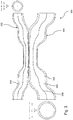
- Figure 5 is an exemplary embodiment illustrating an optical coupler 500 having the second coreless fiber 504 fused with a first optical fiber 502 having a first inner single-mode cladding. Moreover, it is tapered in such a way that the fundamental mode of the single-mode core of the DCF is transformed adiabatically, therefore without loss, into the fundamental mode of the reduced inner-cladding.
- an inner one of the claddings is tapered to form an inner single-mode cladding enabling the single-mode signal propagating along the single-mode core to propagate substantially losslessly (or adiabatically) along the inner single-mode cladding of the first optical fiber.
- the inner-cladding is itself rendered a single-mode guiding region owing to its reduction in diameter.
- the tapered DCF is then fused to another fiber.
- a 9/50/125 double-clad fiber is pre-tapered with a ratio of approximately 5.
- the first tapered and adiabatically transformed double-clad fiber 502 is then fused to the multi-mode fiber.
- the multi-mode fiber may be of standard size or over-sized, and the double-clad fiber may have various ranges of diameters and may be pre-tapered to a different ratio. It has been demonstrated that such an optical fiber coupler can achieve a multi-modal transmission of 80 % with an etendue ratio of 100.
- An example optical fiber coupler 500 having a general construction as described above with reference to Fig. 5 , with a first optical fiber being a DCF 4.1 ⁇ m (0.11 NA)/25.8 ⁇ m (0.19 NA)/125 ⁇ m, the second optical fiber being a coreless fiber of 125 ⁇ m (0.5 NA) and a DCF fiber being tapered by 0.1 ITR characterized with an etendue ratio of 100, has reached a multi-modal transmission of 80 %.
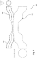
- the optical coupler 600 whereby the first optical fiber 602 is a double-clad fiber and the second optical fiber 604 is a coreless fiber.
- the first double-clad fiber 602 is tapered and adiabatically transformed before being fused to the coreless fiber 604.
- both fibers multiple modes are trapped by the glass/air interface.
- the fused structure allows complete mixing of the multiple modes and a distribution of power proportional to the guiding areas.
- the structure can be fabricated such that the down-tapers 626, 632 of the double-clad fiber 602 is fused to the coreless fiber 604, but not the up-tapers 630, 636.
- This is illustrated in Figure 6 in combination with the coreless fiber, but may be provided with any of the other first optical fiber/second optical fiber configurations described herein.
- This produces an asymmetry about a transverse axis Y, which is centered in the coupling region 606, but can also be provided at various positions upstream and downstream within the coupling region 606.
- the coupling region thus comprises a fused portion and a non-fused portion. This feature minimizes the back-coupling into the cladding of the double-clad fiber.
- the double-clad fiber has dimensions of 9/50/125 that has been tapered with a ratio of approximately 5 and the coreless fiber is a coreless -//125 fiber.
- the ratio of areas being 25, the structure allows a 4/96% multi-mode coupling ratio, where the greater portion is extracted out of the double-clad fiber.
- the coreless -//125 fiber may be end-fused to a -/200/220 multi-mode fiber at end to avoid losses caused by the polymer jacket present over the fiber outside the coupling region.
- Other exemplary dimensions for the double-clad fiber are 4.5/105/125 and 4.5/30/125.
- the asymmetric optical fiber coupler described herein may thus be composed of a double-clad fiber in combination with anyone of a coreless fiber, a single-mode fiber, a multi-mode fiber, and a double-clad fiber.
- asymmetry is created by having the respective cross-sections of the fibers differ in dimensions.
- the respective cross-sections of the fibers will differ in structure in view of the different types of fibers fused together. These configurations may also have cross-sections that differ in dimensions in addition to structure.
- the optical fiber coupler may have double asymmetry, such as that illustrated in Figures 6 and 9 .
- An example optical fiber coupler 600 having a general construction as described above with reference to Fig. 6 , with a first optical fiber being a custom DCF 9 ⁇ m (0.12 NA)/105 ⁇ m (0.19 NA)/125 ⁇ m, the second optical fiber being a coreless fiber of 250 ⁇ m (0.5 NA) and a DCF fiber being tapered by 0.5 ITR characterized with an etendue ratio of 156, has reached a multi-modal transmission of 91 %.
- FIG 7 illustrates an optical coupler 700 having first optical fiber 702 having a single-mode core 714 that guides the single-mode signal.
- the double-clad fiber may be fused with different optical fibers in order to create the asymmetric coupler.
- Some exemplary materials for the double-clad fiber are various polymer and glass types, such as silica (pure or doped).
- the second optical fiber 704 is a multi-mode fiber.
- the larger core 744 supports multi-mode signals and is surrounded by a cladding.
- the multi-mode fiber may have a step-index profile or a graded-index profile. Post-fusion stretching of the structure to reduce the original dimensions by a factor comprised between about 2 and about 3 will allow the light in the core 714 of the double-clad fiber 702 to remain in the single-mode core 714 while allowing the light in the larger inner cladding 716 to escape in part to the multi-mode fiber 704.
- the double-clad fiber may have diameters D1/D2/D3 of 9/105/125 while the multi-mode fiber may have diameters D5/D6 of 220/240.
- This particular combination allows an approximate 23/77% multi-mode coupling ratio, the larger portion coming out of the multi-mode fiber.
- the diameter D1 of the core may vary between about 3.0 ⁇ m and about 10.0 ⁇ m, +/- 20%.
- the diameter D3 of the outer cladding may vary between about 80 ⁇ m and about 200 ⁇ m, +/- 20%.
- the diameter D2 of the inner cladding may also vary.
- the spacing may be about 10.0 ⁇ m or greater while being limited by the diameter D3 of the outer cladding.
- the diameters D5/D6 of the multi-mode fiber may be 125/250, 110/140, 165/190, 430/530, or other possible combinations, provided the desired asymmetry is obtained for the optical coupler.
- the double-clad fiber may be pre-tapered or pristine.
- the reduction in size of the diameters D1/D2/D3 may allow it to be fused with a multi-mode fiber of a smaller size than if the double-clad fiber is not pre-tapered.
- the optical coupler may be obtained using a computer-controlled fusion and tapering setup.
- this setup consists of a traveling oxygen-propane micro-torch on a three-axis motorized stage and of two linear stages for stretching. Other setups may also be used.
- various fabrication techniques may be used to create the optical coupler without starting from commercially available segments.
- Figure 8 illustrates an embodiment whereby an optical coupler 800 having a second optical fiber 804 that is a single-mode fiber is fused with the double-clad fiber 802.
- the single-mode fiber comprises a core 846.
- the asymmetry can be harnessed to maximize the injection of a multi-mode signal from the third port of the second optical fiber into the inner cladding of a multiple-clad fiber, while preserving the core light in the multiple-clad fiber with negligible loss.
- the second optical fiber may be a multi-mode fiber.
- Figure 9 shows an exemplary embodiment 900 where the first optical fiber 902 is a double-clad fiber that has been chemically etched so as to remove the outer cladding 918 along the coupling region 906, and the second optical fiber 904 is a multi-mode fiber that has been pre-tapered, and both cross-talk regions 908 and 920 have been fused only along a given portion of their lengths.
- the double asymmetry thus obtained provides favorable transmission of a multi-mode signal guided from the multi-mode fiber 104 into the inner cladding of the double-clad fiber.
- a 9/105/125 double-clad fiber is fused to a 25/125 multi-mode fiber, pre-tapered by a ratio of 8 before fusion with the double-clad fiber.
- the etendue ratio when injecting a multi-mode signal from the third end of the second optical fiber to the second end of the first optical fiber, the etendue ratio can be 1/2704 while when extracting a multi-mode signal from the second end of the first optical fiber to the third end of the second optical fiber, the etendue ratio can be 2704.
- An example optical fiber coupler 900 having a general construction as described above with reference to Fig. 9 , with a first optical fiber being a custom DCF 9 ⁇ m (0.12 NA)/105 ⁇ m, the second optical fiber being a multimodal fiber of 25.8 ⁇ m (0.19 NA) and the multimodal fiber being tapered by 0.5 ITR characterized with an etendue ratio of 1/2704, has reached a multi-modal injection of 66 %.
- Figure 10 shows an exemplary embodiment of the optical coupler 1000 where the multi-mode fiber 1004 has been pre-tapered prior to fusion with the double-clad fiber 1002.
- the tapered portion of the multi-mode fiber is made longer than the fused portion.
- light escapes from the large core 1044 into the outer cladding.
- a multi-mode signal is preferably guided in the larger double-clad fiber, therefore providing more than 50% of bidirectional transmission from the multi-mode fiber to the inner cladding of the double-clad fiber.
- Figure 11 shows an exemplary embodiment of the optical coupler 1100 where the double-clad fiber 1102 has been chemically etched so as to remove the outer cladding 1118, and the multi-mode fiber 1104 has been pre-tapered. Removal of the outer cladding 1118 of the double-clad fiber 1102 facilitates transfer of the multi-mode signal into its inner cladding 1116.
- the fabrication process begins by stripping the cross-talk portions of the first optical fiber and second optical fiber from their coating and cleaning them with acetone.
- the cross-talk portions fibers are pressed together by holding clamps containing V-shaped grooves and inspected with a microscope mounted over the setup.
- the first optical fiber is spliced with a single-mode fiber (SMF) on both ends and connected respectively to a broadband source and to an optical spectrum analyzer.
- SMF single-mode fiber
- the two fibers are fused side-by-side with a micro-torch traveling over 4-8 mm along the fibers for approximately 2 minutes.
- the coupling region is then stretched, at a slightly lower flame temperature, at a stretching rate of 0.1 mm/s, with the micro-torch traveling back-and-forth along a constant 8 mm length.
- the device may be packaged on a quartz substrate while still under tension on the setup and then inserted in a stainless steel tube.
- Core signal transmission of the exemplary double-clad fiber coupler (DCFC) may be monitored during fabrication with a conventional broadband source and an optical spectrum analyzer.
- Figure 12 shows an exemplary embodiment of the optical coupler 1200 where the first optical fiber 1202 is a triple-clad fiber and the second optical fiber 1204 is a multimode fiber.
- the first triple-clad fiber 1204 has a single-mode core 1214, first inner multi-mode claddings 1216a and 1216b, and a first outer cladding 1218.
- the multi-mode signal can be transmitted from the larger core 1244 of the second optical fiber 1204 to the larger one of the first inner multi-mode claddings 1216a and 1216b.
- the first inner multi-mode cladding 1216a can be large enough to guide the multimode signal.
- the etendue of the first optical fiber can be calculated based on the NA of the conducting first inner multi-mode cladding, for instance.
- the asymmetric optical couplers illustrated heretofore harness the asymmetry to maximize the extraction of a multi-mode signal from a multiple-clad fiber.
- This allows the assembly of biomedical imaging systems (such as endoscopy, confocal endomicroscopy, spectroscopy) operating at the theoretically minimal amount of signal loss for both the single-mode and the multi-mode portions. It also supports the combination of modalities.
- the design is capable of collecting >70% of light from the inner cladding area, while still transmitting nearly all the single-mode signal over a wide spectral region (1250 nm to 1350 nm).
- the asymmetric optical coupler may also be implemented in a spectral endoscopy (SEE) setup, which allows the acquisition of speckle-free images (1000x1000 pixels) at 30 frames per second. Three-dimensional reconstructions may be created by coupling the core signal to an interferometer.
- Figure 13 is an exemplary embodiment of a setup for single fiber endoscopy using the asymmetric optical coupler 1300, for instance.
- a laser 1348 provides illumination at port 1 of the coupler 1300.
- a scanner 1350 samples the signal output from port 2.
- Three-dimensional interferometric detection 1352 occurs via port 1 through the circulator 1354 and through line delay 1356.
- Multimodal endoscopic detection 1362 may be performed via port 3 of the coupler 1300.
- the asymmetric optical coupler 1300 removes speckle from the detection performed at both ports 1 and 3.
- Figure 14 is an exemplary embodiment of a setup for confocal microendoscopy/microscopy using the asymmetric optical coupler 1400.
- a laser 1448 provides illumination at port 1 of the coupler 1400.
- a scanner 1450 with a tapered end 1458 samples the signal output from port 2.
- Endoscopic detection 1460 occurs via port 1 through the circulator 1454.
- Multimodal confocal detection 1464 fluorescence, Raman, Spectroscopy
- the asymmetric optical coupler again removes speckle from the detection performed at both ports 1 and 3.
- Figure 15 is an exemplary embodiment of a setup for optical coherence tomography (OCT) and multimodal detection using the asymmetric optical coupler 1500.
- a first laser 1548 provides illumination at port 1 of the coupler 1500 for the OCT.
- a scanner 1550 samples the signal output from port 2.
- OCT detection 1566 occurs via port 1 through the circulator 1554 and through line delay 1556.
- a second laser 1568 provides illumination at port 1 for multimodal detection 1570 (fluorescence, Raman, Spectroscopy) performed via port 3 of the coupler 1500.
- Figure 16 also illustrates an example of an image guided therapeutic system for laser ablation using the asymmetric optical coupler 1600, thermal therapy and/or coagulation.
- a therapeutic laser 1672 can be injected into the port 3 of the second optical fiber.
- the asymmetric optical coupler 1600 can therefore propagate a therapeutic beam from port 3 to port 2, where it can be provided to a sample using a therapeutic beam provider 1674.
- the asymmetric optical couplers presented in Figures 2 to 8 can be used, However, the optical couplers presented in Figures 9 , 10 and 11 are preferred.
- the double-clad fiber may be replaced by a multiple-clad fiber containing a core, multiple inner claddings, and an outer cladding, wherein any two consecutive regions have different refractive indices.
Landscapes
- Physics & Mathematics (AREA)
- General Physics & Mathematics (AREA)
- Optics & Photonics (AREA)
- Optical Couplings Of Light Guides (AREA)
- Endoscopes (AREA)
- Instruments For Viewing The Inside Of Hollow Bodies (AREA)
- Microscoopes, Condenser (AREA)
Description
- The present invention relates to the field of optical couplers and more particularly, to such couplers for endoscopy, optical coherence tomography, confocal microscopy and confocal endomicroscopy.
- Optical fiber couplers are used in many types of imaging and sensing systems with one or more input fibers and one or several output fibers. Such couplers can be fabricated in different ways, for example by thermally fusing fibers so that their cores get into intimate contact. In many medical imaging systems, illumination is provided at a first port of the coupler via a laser source, sampling of an output signal occurs at a second port of the coupler via a scanning device, and detection can occur at both the first port and a third port of the coupler. Various types of detection are possible, depending on the application.
US2012/0154783 ,US2010/0183261 andWO2010/057288 describe various optical fiber couplers. - Medical imaging systems based on optical fiber couplers typically face two major challenges: 1) speckle which is an issue related to temporally and spatially coherent imaging when using lasers and single-mode fibers and 2) a theoretical equipartition limit to the amount of the multi-mode signal that can be extracted from the second port to the third port and injected from the third port to the second port.
- There is therefore a need to develop optical fiber couplers that can overcome these challenges, and particularly, a need to develop improved optical fiber couplers for medical imaging and sensing applications.
- It is known that the optical couplers of the prior art are limited by the theoretical equipartition limit of multi-modal transmission of 50 %, as the first and second fibers was characterized by the same dimension and the same structure (see
U.S. Patent Application No. 2012/0190928 , the contents of which are hereby incorporated by reference). The highest multi-modal transmission for such optical couplers was found to be 43 %. Although near the theoretical equipartition limit of 50 %, achieving near or above 43 % was found to be challenging. - There is described herein an asymmetrical optical coupler which has a theoretical limit differing from and not limited to the theoretical equipartition limit of the optical fiber coupler of the prior art. Therefore achieving a multi-modal transmission above than 50 % is possible.
- It was found that the asymmetry of the optical fiber coupler can be quantified by an etendue ratio which is defined as G3/G1, where Gi is given by :

- Described herein is a multiple-clad optical fiber having a single-mode core guiding a single-mode signal and at least one inner multi-mode cladding guiding multiple modes (also referred to as a multi-mode signal). The multiple-clad fiber can be optically coupled with a second fiber of a different etendue along a coupling region to create an optical fiber coupler having enhanced optical transfer functions bidirectionally between the multiple-clad fiber and the second fiber. The different etendue can be provided by at least one of a different cross-section area and a different numerical aperture.
- In accordance with a first aspect, there is provided an optical fiber coupler as claimed in
claim 1. In embodiments, the optical fiber coupler can achieve a multi-modal transmission above 50 %, preferably above 60 % and most preferably above 70 %. - In accordance with another aspect, there is provided an optical fiber coupler which can be characterized by an etendue ratio above 1.5, preferably above 2, and most preferably above 10.
- In accordance with another aspect, there is provided an optical fiber coupler comprising: a first optical fiber having a first cross-talk portion located between a first end and a second end, and having a first single-mode core, at least one inner multi-mode cladding, and a first outer cladding, the first cross-talk portion having a first etendue; a second optical fiber having a second cross-talk portion located between a third end and a fourth end, the second cross-talk portion having a second etendue, the second etendue forming an etendue ratio differing from one relative to the first etendue; and a coupling region where the first cross-talk portion is optically coupled to the second cross-talk portion; wherein the etendue ratio is indicative of a transmission of a multi-mode signal between the second end of the first optical fiber and the third end of the second optical fiber.
- In accordance with another aspect, there is provided a method for making an optical coupler as claimed in claim 12.
- An optical coupler as described herein can be used in an imaging system for interferometric detection, endoscopy, multimodal endoscopy, confocal endomicroscopy, confocal microscopy, nonlinear microscopy, nonlinear endomicroscopy, optical coherence tomography, and other applications, as will be described in more detail below.
- In one embodiment, the fused region allows nearly lossless transmission of the single-mode signal along the single-mode core, from the first port to the second port, and vice-versa. More specifically, there is provided an optical fiber coupler which can achieve a mono-modal transmission above 85 %, preferably above 90 % and most preferably above 95 %.
- In another embodiment, more than 70% of the multi-mode signal can be extracted from the second port to the third port of the optical coupler. More specifically, more than 50 % of the multi-mode signal can be extracted from the at least one inner cladding of the multiple-clad fiber to the second fiber. In some other embodiments, extraction of the multiple-mode signal from the second port to the third port can be comprised between about 60% and about 70%. In some embodiments, extraction of the multiple modes is greater than 50 %.
- In accordance with another aspect, there is provided an optical coupler that can be used in a therapeutic system based on laser ablation, thermal therapy and/or coagulation. In this case, optical fiber couplers are used to launch an imaging laser through the single-mode core of the multiple-clad fiber and to launch a therapeutic laser in the at least one inner cladding of the multiple-clad fiber through the third port of the fiber coupler.
- In another embodiment, more than 50% of the multi-mode signal can be injected from the third port to the second port of the optical coupler. More specifically, more than 50 % of the multi-mode signal can be injected from the second fiber to the at least one inner cladding of the multiple-clad fiber.
- In another embodiment, the first core of the first fiber is adiabatically transformed into a fundamental mode of a reduced first inner cladding by the pre-tapering, and the reduced inner cladding is transformed into a single-mode guiding region.
- In another embodiment, the fused region is limited to either a down-tapered or an up-tapered portion of the first and the second fibers.
- Many further features and combinations thereof concerning the present improvements will appear to those skilled in the art following a reading of the instant disclosure.
- Further features and advantages of the present invention will become apparent from the following detailed description, taken in combination with the appended drawings, in which:
-
Fig. 1 is a graph showing examples of the transmission of a multi-mode signal from a first optical fiber to a second optical fiber as a function of an etendue ratio; -
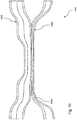
Fig. 2 illustrates a generic embodiment of the optical fiber coupler; -
Fig. 3 illustrates an embodiment of the optical fiber coupler having first and second double-clad fibers of different dimensions; -
Fig. 4 illustrates an embodiment of the optical fiber coupler having a first chemically etched double-clad fiber; -
Fig. 5 illustrates an embodiment of the optical fiber coupler having a first optical fiber transformed to obtain an inner single-mode cladding; -
Fig. 6 illustrates an embodiment of the optical fiber coupler having a first double-clad fiber and a second coreless fiber which exhibits asymmetry between a down-stream portion and an up-stream portion of a coupling region; -
Fig. 7 illustrates an embodiment of the optical fiber coupler having a first double-clad fiber and a second multi-mode fiber; -
Fig. 8 illustrates an embodiment of the optical fiber coupler having a first double-clad fiber and a second single-mode fiber; -
Fig. 9 illustrates an embodiment of the optical fiber coupler having a first chemically etched double-clad fiber and a second pre-tapered multi-mode fiber wherein the first and second fibers are fused only in a down-stream portion of a coupling region; -
Fig. 10 illustrates an embodiment of the optical fiber coupler having a second pre-tapered multi-mode fiber; -
Fig. 11 illustrates an embodiment of the optical fiber coupler having a first chemically etched double-clad fiber and a second pre-tapered multi-mode fiber; -
Fig. 12 illustrates an embodiment of the optical fiber coupler having a first optical fiber having a first single-mode core, first inner claddings and a first outer cladding and a second multi-mode fiber. -
Fig. 13 illustrates an exemplary setup for single fiber endoscopy using an asymmetrical optical fiber coupler; -
Fig. 14 illustrates an exemplary setup for confocal microendoscopy/microscopy using the asymmetrical optical fiber coupler; -
Fig. 15 illustrates an exemplary setup for combined optical coherence tomography and fluorescence (or Raman) detection using the asymmetrical optical fiber coupler; and -
Fig. 16 illustrates an exemplary setup for an image guided therapeutic system using the asymmetrical optical fiber coupler. - It will be noted that throughout the appended drawings, like features are identified by like reference numerals.
-
Figure 1 is a graph showing examples of the transmission of a multi-mode signal from a first optical fiber to a second optical fiber as a function of an etendue ratio for an optical coupler of theprior art 100. The new theoretical model for asymmetrical optical fiber couplers is represented by the solid line ofFigure 1 . More specifically,Figure 1 shows multi-modal transmissions of 53 %, 75 %, 80 % and 91 % for, respectively, asymmetricaloptical couplers Figs. 3 ,4 ,5 , and6 . Moreover, other possible configurations for the asymmetrical coupler are presented inFigs. 2 to 12 . -
Figure 2 is a schematic diagram of anoptical fiber coupler 200 having asymmetrical geometry and optical transfer functions. A firstoptical fiber 202 is fused with a secondoptical fiber 204 at a coupling region 206 (or fused region). The fibers can be fused side by side at high temperature, for example using a micro-torch as a heat source. Thecoupling region 206 is then pulled and tapered such that its cross-section is reduced, inducing coupling of the light from one fiber to the other. The firstoptical fiber 202 has afirst cross-talk portion 208 between afirst end 210 and asecond end 212. The firstoptical fiber 202 also has a first single-mode core 214, a first innermulti-mode cladding 216 and a firstouter cladding 218. The secondoptical fiber 204 has asecond cross-talk portion 220 between athird end 222 and afourth end 224. - The multi-modal transmission enhancement can be provided by the difference in etendue between the
first cross-talk portion 208 of the firstoptical fiber 202 and thesecond cross-talk portion 220 of the second optical fiber 204 (and also by optically coupling the cross-talk portions one to one another along only a portion of their lengths, which can increase and/and amplify the multi-modal transmission, seeFigure 6 ). This in turn provides asymmetrical optical transfer functions by maintaining a single-mode signal in the single-mode core 214 of thefirst fiber 202 and transmitting at least part of a multi-mode signal from at least oneinner cladding 216 of thefirst fiber 202 to thesecond fiber 204. Although the first optical fiber is illustrated as a double-clad fiber (DCF) inFig. 2 , the first optical fiber can be another form of multiple-clad fiber, such as a triple or perhaps even a quadruple inner clad fiber for instance (seeFigure 12 ). - The
coupling region 206 is composed of thecross-talk portion 208 of thefirst fiber 202 fused to thecross-talk portion 220 of thesecond fiber 204. In thecoupling region 206, the single-mode cores of fibers remain separate. Thefirst cross-talk portion 208 has a first down-stream section 226 (or a first diameter transition section), a firstconstant diameter section 228, and a first up-stream section 230 (or a second diameter transition section). Thesecond cross-talk portion 220 has a second down-stream section 232, a secondconstant diameter section 234, and a second up-stream section 236. The first and second down-stream sections coupling region 206 and the first and second up-stream sections coupling region 206. Thecoupling region 206 has a predetermined taper ratio. The predetermined taper ratio may vary between about 0.1 and about 0.6. -
Figure 3 illustrates an embodiment for theoptical coupler 300 whereby the firstoptical fiber 302 is a double-clad fiber fused with the secondoptical fiber 304 which is also a double-clad fiber. The second double-clad fiber comprises a second single-mode core 338 that supports a single guiding mode and a second innermulti-mode cladding 340, surrounded by a secondouter cladding 342, that guides a multi-mode signal. The first double-cladfiber 302 and the second double-cladfiber 304 may be identical or may have slight differences in terms of dimensions. If so, the first double-cladfiber 304 is tapered to reduce its dimensions while the second double-cladfiber 304 is not, thereby creating the geometrical asymmetry or an etendue difference (which can lead to an etendue ratio above or below one). The first double-cladfiber 302 may be pre-tapered by a factor of about 2 and then fused to a pristine double-cladfiber 304. The structure may be further tapered. The resulting coupler has an etendue difference and may exhibit coupling of the multi-mode portion due to the different diameters of the inner-claddings - An example
optical fiber coupler 300 having a general construction as described above with reference toFig. 3 , with first and second optical fiber being characterized with an etendue ratio of 1.5, has reached a multi-modal transmission of 53 %. - The asymmetry may be provided using various techniques. For example, the cross-talk portions of the fibers may differ in dimensions and/or structure from their initial construction. Alternatively or in combination therewith, at least one of the two fibers may be transformed post-fabrication and pre-fusion. Transformation may occur using pre-tapering, thus reducing an initial diameter of a fiber. Transformation may also occur using chemical etching, whereby an outer material of one or both fibers is removed.
Figure 4 is an exemplary embodiment illustrating anoptical coupler 400 having a double-cladfiber 402 where a portion of anouter cladding 418 has been chemically etched at least along the coupling region 406 and then fused to the secondcoreless fiber 404. In this example, chemical etching is performed by inserting a fiber segment into a solution of 20% hydrofluoric acid. Other acids may also be used to remove part of the outer cladding. Other processes may be used to remove part of the outer cladding, such as plasma etching or polishing. - An example
optical fiber coupler 400 having a general construction as described above with reference toFig. 4 , with a first optical fiber being a DCF Nufern 9 µm(0.12 NA)/105 µm(0.20 NA)/125 µm and the second optical fiber being a coreless fiber of 200 µm (0.22 NA), characterized with an etendue ratio of 3.6, has reached a multi-modal transmission of 75 %. -
Figure 5 is an exemplary embodiment illustrating anoptical coupler 500 having the secondcoreless fiber 504 fused with a firstoptical fiber 502 having a first inner single-mode cladding. Moreover, it is tapered in such a way that the fundamental mode of the single-mode core of the DCF is transformed adiabatically, therefore without loss, into the fundamental mode of the reduced inner-cladding. In other words, an inner one of the claddings is tapered to form an inner single-mode cladding enabling the single-mode signal propagating along the single-mode core to propagate substantially losslessly (or adiabatically) along the inner single-mode cladding of the first optical fiber. The inner-cladding is itself rendered a single-mode guiding region owing to its reduction in diameter. The tapered DCF is then fused to another fiber. For example, a 9/50/125 double-clad fiber is pre-tapered with a ratio of approximately 5. The first tapered and adiabatically transformed double-cladfiber 502 is then fused to the multi-mode fiber. The multi-mode fiber may be of standard size or over-sized, and the double-clad fiber may have various ranges of diameters and may be pre-tapered to a different ratio. It has been demonstrated that such an optical fiber coupler can achieve a multi-modal transmission of 80 % with an etendue ratio of 100. - An example
optical fiber coupler 500 having a general construction as described above with reference toFig. 5 , with a first optical fiber being a DCF 4.1 µm (0.11 NA)/25.8 µm (0.19 NA)/125 µm, the second optical fiber being a coreless fiber of 125 µm (0.5 NA) and a DCF fiber being tapered by 0.1 ITR characterized with an etendue ratio of 100, has reached a multi-modal transmission of 80 %. - Turning now to
figure 6 , there is illustrated an embodiment for theoptical coupler 600 whereby the firstoptical fiber 602 is a double-clad fiber and the secondoptical fiber 604 is a coreless fiber. In this embodiment, the first double-cladfiber 602 is tapered and adiabatically transformed before being fused to thecoreless fiber 604. In both fibers, multiple modes are trapped by the glass/air interface. The fused structure allows complete mixing of the multiple modes and a distribution of power proportional to the guiding areas. - In some embodiments, the structure can be fabricated such that the down-
tapers fiber 602 is fused to thecoreless fiber 604, but not the up-tapers Figure 6 in combination with the coreless fiber, but may be provided with any of the other first optical fiber/second optical fiber configurations described herein. This produces an asymmetry about a transverse axis Y, which is centered in thecoupling region 606, but can also be provided at various positions upstream and downstream within thecoupling region 606. The coupling region thus comprises a fused portion and a non-fused portion. This feature minimizes the back-coupling into the cladding of the double-clad fiber. - In one exemplary embodiment, the double-clad fiber has dimensions of 9/50/125 that has been tapered with a ratio of approximately 5 and the coreless fiber is a coreless -//125 fiber. The ratio of areas being 25, the structure allows a 4/96% multi-mode coupling ratio, where the greater portion is extracted out of the double-clad fiber. The coreless -//125 fiber may be end-fused to a -/200/220 multi-mode fiber at end to avoid losses caused by the polymer jacket present over the fiber outside the coupling region. Other exemplary dimensions for the double-clad fiber are 4.5/105/125 and 4.5/30/125.
- The asymmetric optical fiber coupler described herein may thus be composed of a double-clad fiber in combination with anyone of a coreless fiber, a single-mode fiber, a multi-mode fiber, and a double-clad fiber. When combining the double-clad fiber with another double-clad fiber, asymmetry is created by having the respective cross-sections of the fibers differ in dimensions. In all other cases, the respective cross-sections of the fibers will differ in structure in view of the different types of fibers fused together. These configurations may also have cross-sections that differ in dimensions in addition to structure. The optical fiber coupler may have double asymmetry, such as that illustrated in
Figures 6 and9 . - An example
optical fiber coupler 600 having a general construction as described above with reference toFig. 6 , with a first optical fiber being a custom DCF 9 µm (0.12 NA)/105 µm (0.19 NA)/125 µm, the second optical fiber being a coreless fiber of 250 µm (0.5 NA) and a DCF fiber being tapered by 0.5 ITR characterized with an etendue ratio of 156, has reached a multi-modal transmission of 91 %. - Reference is made to
figure 7 , which illustrates anoptical coupler 700 having firstoptical fiber 702 having a single-mode core 714 that guides the single-mode signal. A largerinner cladding 716, surrounded by anouter cladding 718, guiding multiple modes. The double-clad fiber may be fused with different optical fibers in order to create the asymmetric coupler. Some exemplary materials for the double-clad fiber are various polymer and glass types, such as silica (pure or doped). - In some embodiments, the second
optical fiber 704 is a multi-mode fiber. Thelarger core 744 supports multi-mode signals and is surrounded by a cladding. The multi-mode fiber may have a step-index profile or a graded-index profile. Post-fusion stretching of the structure to reduce the original dimensions by a factor comprised between about 2 and about 3 will allow the light in thecore 714 of the double-cladfiber 702 to remain in the single-mode core 714 while allowing the light in the largerinner cladding 716 to escape in part to themulti-mode fiber 704. - Various size combinations are possible between the double-clad
fiber 702 and themulti-mode fiber 704. For example, the double-clad fiber may have diameters D1/D2/D3 of 9/105/125 while the multi-mode fiber may have diameters D5/D6 of 220/240. This particular combination allows an approximate 23/77% multi-mode coupling ratio, the larger portion coming out of the multi-mode fiber. The diameter D1 of the core may vary between about 3.0 µm and about 10.0 µm, +/- 20%. The diameter D3 of the outer cladding may vary between about 80 µm and about 200 µm, +/- 20%. The diameter D2 of the inner cladding may also vary. It may be as large as possible while allowing enough spacing with the outer cladding to guide light substantially losslessly. For example, the spacing may be about 10.0 µm or greater while being limited by the diameter D3 of the outer cladding. The diameters D5/D6 of the multi-mode fiber may be 125/250, 110/140, 165/190, 430/530, or other possible combinations, provided the desired asymmetry is obtained for the optical coupler. - The double-clad fiber may be pre-tapered or pristine. In the case of a pre-tapered double-clad fiber, the reduction in size of the diameters D1/D2/D3 may allow it to be fused with a multi-mode fiber of a smaller size than if the double-clad fiber is not pre-tapered. When created from commercially available segments, the optical coupler may be obtained using a computer-controlled fusion and tapering setup. In one embodiment, this setup consists of a traveling oxygen-propane micro-torch on a three-axis motorized stage and of two linear stages for stretching. Other setups may also be used. Alternatively, various fabrication techniques may be used to create the optical coupler without starting from commercially available segments.
-
Figure 8 illustrates an embodiment whereby anoptical coupler 800 having a secondoptical fiber 804 that is a single-mode fiber is fused with the double-cladfiber 802. The single-mode fiber comprises acore 846. - In one embodiment, the asymmetry can be harnessed to maximize the injection of a multi-mode signal from the third port of the second optical fiber into the inner cladding of a multiple-clad fiber, while preserving the core light in the multiple-clad fiber with negligible loss. In such an embodiment, the second optical fiber may be a multi-mode fiber.
-
Figure 9 shows anexemplary embodiment 900 where the firstoptical fiber 902 is a double-clad fiber that has been chemically etched so as to remove theouter cladding 918 along thecoupling region 906, and the secondoptical fiber 904 is a multi-mode fiber that has been pre-tapered, and bothcross-talk regions - An example
optical fiber coupler 900 having a general construction as described above with reference toFig. 9 , with a first optical fiber being a custom DCF 9 µm (0.12 NA)/105 µm, the second optical fiber being a multimodal fiber of 25.8 µm (0.19 NA) and the multimodal fiber being tapered by 0.5 ITR characterized with an etendue ratio of 1/2704, has reached a multi-modal injection of 66 %. -
Figure 10 shows an exemplary embodiment of theoptical coupler 1000 where themulti-mode fiber 1004 has been pre-tapered prior to fusion with the double-cladfiber 1002. The tapered portion of the multi-mode fiber is made longer than the fused portion. In the tapered portion of themulti-mode fiber 1004 light escapes from thelarge core 1044 into the outer cladding. In the up-taper portion of the coupler, a multi-mode signal is preferably guided in the larger double-clad fiber, therefore providing more than 50% of bidirectional transmission from the multi-mode fiber to the inner cladding of the double-clad fiber. -
Figure 11 shows an exemplary embodiment of theoptical coupler 1100 where the double-cladfiber 1102 has been chemically etched so as to remove theouter cladding 1118, and themulti-mode fiber 1104 has been pre-tapered. Removal of theouter cladding 1118 of the double-cladfiber 1102 facilitates transfer of the multi-mode signal into itsinner cladding 1116. - In one embodiment, the fabrication process begins by stripping the cross-talk portions of the first optical fiber and second optical fiber from their coating and cleaning them with acetone. The cross-talk portions fibers are pressed together by holding clamps containing V-shaped grooves and inspected with a microscope mounted over the setup. For on-line characterization of the core mode transmission, the first optical fiber is spliced with a single-mode fiber (SMF) on both ends and connected respectively to a broadband source and to an optical spectrum analyzer. The two fibers are fused side-by-side with a micro-torch traveling over 4-8 mm along the fibers for approximately 2 minutes. The coupling region is then stretched, at a slightly lower flame temperature, at a stretching rate of 0.1 mm/s, with the micro-torch traveling back-and-forth along a constant 8 mm length. The device may be packaged on a quartz substrate while still under tension on the setup and then inserted in a stainless steel tube. Core signal transmission of the exemplary double-clad fiber coupler (DCFC) may be monitored during fabrication with a conventional broadband source and an optical spectrum analyzer.
-
Figure 12 shows an exemplary embodiment of theoptical coupler 1200 where the firstoptical fiber 1202 is a triple-clad fiber and the secondoptical fiber 1204 is a multimode fiber. The first triple-cladfiber 1204 has a single-mode core 1214, first innermulti-mode claddings outer cladding 1218. In this case, the multi-mode signal can be transmitted from thelarger core 1244 of the secondoptical fiber 1204 to the larger one of the first innermulti-mode claddings Figure 12 , the first innermulti-mode cladding 1216a can be large enough to guide the multimode signal. The etendue of the first optical fiber can be calculated based on the NA of the conducting first inner multi-mode cladding, for instance. - The asymmetric optical couplers illustrated heretofore harness the asymmetry to maximize the extraction of a multi-mode signal from a multiple-clad fiber. This allows the assembly of biomedical imaging systems (such as endoscopy, confocal endomicroscopy, spectroscopy) operating at the theoretically minimal amount of signal loss for both the single-mode and the multi-mode portions. It also supports the combination of modalities. The design is capable of collecting >70% of light from the inner cladding area, while still transmitting nearly all the single-mode signal over a wide spectral region (1250 nm to 1350 nm). This design allows for an improvement of the signal to noise ratio, which can be used to detect weaker signals (such as fluorescence or Raman) or to image in vivo samples faster. The asymmetric optical coupler may also be implemented in a spectral endoscopy (SEE) setup, which allows the acquisition of speckle-free images (1000x1000 pixels) at 30 frames per second. Three-dimensional reconstructions may be created by coupling the core signal to an interferometer. Some of the setups and techniques described in co-pending United States application bearing publication No.
2012/0190928 , the contents of which are hereby incorporated by reference, were repeated with the present optical coupler. -
Figure 13 is an exemplary embodiment of a setup for single fiber endoscopy using the asymmetricoptical coupler 1300, for instance. Alaser 1348 provides illumination atport 1 of thecoupler 1300. Ascanner 1350 samples the signal output fromport 2. Three-dimensional interferometric detection 1352 occurs viaport 1 through thecirculator 1354 and throughline delay 1356. Multimodal endoscopic detection 1362 (fluorescence, Raman, Spectroscopy) may be performed viaport 3 of thecoupler 1300. In this setup, the asymmetricoptical coupler 1300 removes speckle from the detection performed at bothports -
Figure 14 is an exemplary embodiment of a setup for confocal microendoscopy/microscopy using the asymmetricoptical coupler 1400. Alaser 1448 provides illumination atport 1 of thecoupler 1400. Ascanner 1450 with a tapered end 1458 (as described in co-pending United States application bearing publication No.2012/0190928 ) samples the signal output fromport 2.Endoscopic detection 1460 occurs viaport 1 through thecirculator 1454. Multimodal confocal detection 1464 (fluorescence, Raman, Spectroscopy) may be performed viaport 3 of thecoupler 1400. In this setup, the asymmetric optical coupler again removes speckle from the detection performed at bothports -
Figure 15 is an exemplary embodiment of a setup for optical coherence tomography (OCT) and multimodal detection using the asymmetricoptical coupler 1500. Afirst laser 1548 provides illumination atport 1 of thecoupler 1500 for the OCT. Ascanner 1550 samples the signal output fromport 2.OCT detection 1566 occurs viaport 1 through thecirculator 1554 and throughline delay 1556. Asecond laser 1568 provides illumination atport 1 for multimodal detection 1570 (fluorescence, Raman, Spectroscopy) performed viaport 3 of thecoupler 1500. -
Figure 16 also illustrates an example of an image guided therapeutic system for laser ablation using the asymmetricoptical coupler 1600, thermal therapy and/or coagulation. In this embodiment, atherapeutic laser 1672 can be injected into theport 3 of the second optical fiber. The asymmetricoptical coupler 1600 can therefore propagate a therapeutic beam fromport 3 toport 2, where it can be provided to a sample using atherapeutic beam provider 1674. When using a therapeutic system, the asymmetric optical couplers presented inFigures 2 to 8 can be used, However, the optical couplers presented inFigures 9 ,10 and11 are preferred. - It is understood that although a therapeutic system using the asymmetric optical coupler is shown concurrently with a setup for OCT, the therapeutic system using the asymmetric optical coupler can be used independent from any detection schemes as well as with other detection schemes through
port 1. In all embodiments described heretofore, the double-clad fiber may be replaced by a multiple-clad fiber containing a core, multiple inner claddings, and an outer cladding, wherein any two consecutive regions have different refractive indices. - Other setups to harness the asymmetry of the optical coupler for purposes of maximizing light extraction and/or removing speckle may also be provided. The embodiments of the invention described above are intended to be exemplary only. The scope of the invention is therefore intended to be limited solely by the scope of the appended claims.
Claims (14)
- An optical fiber coupler (500) comprising:a first optical fiber (502) having a first cross-talk portion located between a first end and a second end, and having a first single-mode core, at least one inner multi-mode cladding, and a first outer cladding, the first cross-talk portion having a first etendue;a second optical fiber (504) having a second cross-talk portion located between a third end and a fourth end, the second cross-talk portion having a second etendue, the second etendue forming an etendue ratio differing from one relative to the first etendue; anda coupling region where the first cross-talk portion is optically coupled to the second cross-talk portion;wherein the etendue ratio is indicative of a transmission of a multi-mode signal between the second end of the first optical fiber (502) and the third end of the second optical fiber (504);wherein a first cross-sectional area of the at least one inner multi-mode cladding of the first optical fiber is different from a second cross-sectional area of the second optical fiber; andwherein an inner one of the at least one inner multi-mode cladding is tapered to form an inner single-mode cladding enabling the single-mode signal propagating along the single-mode core to propagate adiabatically along the inner single-mode cladding of the first optical fiber.
- The optical fiber coupler of claim 1, wherein said etendue ratio is selected such that the transmission of the multi-mode signal is above 50 %, preferably above 60 %, and most preferably above 70 %.
- The optical fiber coupler of claim 1 or 2, wherein the etendue ratio is above 1.5, preferably above 2, and most preferably above 10.
- The optical fiber coupler of any preceding claim, wherein the cross-talk portions are optically coupled to one another along only a portion of their lengths.
- The optical fiber coupler of claim 4, wherein the first cross-talk portion has a first down-stream portion, a first constant diameter portion and a first up-stream portion; the second cross-talk portion having a second down-stream portion, a second constant diameter portion and a second up-stream portion; and wherein the coupling region optically joins either the first down-stream portion or the first up-stream portion and a certain section of the first constant diameter portion of the first cross-talk portion to a corresponding one of the second up-stream portion or the second down-stream portion and a corresponding portion of the second cross-talk portion.
- The optical fiber coupler of any preceding claim, wherein a first numerical aperture of the at least one inner multi-mode cladding of the first optical fiber is different from a second numerical aperture of the second optical fiber.
- The optical fiber coupler of any preceding claim, wherein the second optical fiber is one of a multi-mode optical fiber, a single-mode optical fiber, a double-clad optical fiber, a multiple-clad optical fiber and a coreless optical fiber.
- The optical fiber coupler of any one of the preceding claims, wherein the etendue ratio is above one and the multi-mode signal in the at least one inner multi-mode cladding of the first optical fiber is transmitted to the second optical fiber.
- The optical fiber coupler of any preceding claim, wherein the outer cladding of the first fiber is removed at least along the first cross-talk portion or along the first middle portion prior to the coupling or fusing of the first fiber to the second fiber.
- The optical fiber coupler of any preceding claim, wherein the first fiber is pre-tapered, optionally wherein at least a portion of the first cross-talk portion or first middle portion of the first optical fiber is pre-tapered prior to coupling or fusing of the first fiber to the second optical fiber.
- The optical fiber couple of any preceding claim, wherein said first optical fiber (502) is a double-clad optical fiber.
- A method for making an optical coupler as claimed in any of claims 1 to 11 comprising:providing a first optical fiber (502) having a first end, a second end, a first cross-talk portion therebetween, and having a first core, at least one inner cladding, and a first outer cladding, the first cross-talk portion having a first etendue;providing a second optical fiber (504) having a third end, a fourth end, a second cross-talk portion therebetween, the second cross-talk portion having a second etendue, the second etendue differing from the first etendue;positioning at least a certain section of the first cross-talk portion of the first optical fiber in contact and along a certain section of the second cross-talk portion of the second optical fiber; andproviding heat to both certain sections of the first and second cross-talk portions in a manner forming a fused region;wherein the fused region allows a single-mode signal to remain in the first core between the first end and the second end of the first optical fiber, and for a multi-mode signal in one of the at least one inner cladding to be bidirectionally transmitted to the second fiber.
- The method of claim 12 wherein said providing a first optical fiber further comprises tapering at least the first cross-talk portion and/or chemically etching the first outer cladding at least along a certain portion of the first cross-talk portion prior to the steps of positioning and providing.
- The method of claim 12 or 13 wherein said providing a second optical fiber further comprises tapering at least the first cross-talk portion and/or chemically etching an outer cladding of the second optical fiber at least along a certain portion of the second cross-talk portion prior to the steps of positioning and providing.
Applications Claiming Priority (2)
| Application Number | Priority Date | Filing Date | Title |
|---|---|---|---|
| US201361759482P | 2013-02-01 | 2013-02-01 | |
| PCT/CA2014/050065 WO2014117277A1 (en) | 2013-02-01 | 2014-01-31 | Asymmetric optical fiber coupler |
Publications (3)
| Publication Number | Publication Date |
|---|---|
| EP2951627A1 EP2951627A1 (en) | 2015-12-09 |
| EP2951627A4 EP2951627A4 (en) | 2016-08-31 |
| EP2951627B1 true EP2951627B1 (en) | 2018-10-24 |
Family
ID=51261360
Family Applications (1)
| Application Number | Title | Priority Date | Filing Date |
|---|---|---|---|
| EP14746519.9A Active EP2951627B1 (en) | 2013-02-01 | 2014-01-31 | Asymmetric optical fiber coupler |
Country Status (9)
| Country | Link |
|---|---|
| US (1) | US9753222B2 (en) |
| EP (1) | EP2951627B1 (en) |
| JP (1) | JP6388603B2 (en) |
| CN (1) | CN105103019B (en) |
| AU (1) | AU2014211965B2 (en) |
| CA (1) | CA2899953C (en) |
| DK (1) | DK2951627T3 (en) |
| IL (1) | IL240235B (en) |
| WO (1) | WO2014117277A1 (en) |
Families Citing this family (20)
| Publication number | Priority date | Publication date | Assignee | Title |
|---|---|---|---|---|
| EP2951627B1 (en) * | 2013-02-01 | 2018-10-24 | Polyvalor, Limited Partnership | Asymmetric optical fiber coupler |
| US9198478B2 (en) | 2013-03-05 | 2015-12-01 | Nike, Inc. | Support members with variable viscosity fluid for footwear |
| WO2017101051A1 (en) * | 2015-12-17 | 2017-06-22 | 上海交通大学 | Optical fibre coupler for non-circular symmetrical mode |
| CN105866887A (en) * | 2016-05-09 | 2016-08-17 | 南方科技大学 | Cladding light stripper, manufacturing device and manufacturing method thereof, and packaging structure |
| US10578422B2 (en) | 2016-06-08 | 2020-03-03 | Canon U.S.A., Inc. | Devices, systems, methods and storage mediums using full range optical coherence tomography |
| US10323926B2 (en) | 2017-06-21 | 2019-06-18 | Canon U.S.A., Inc. | Crosstalk elimination or mitigation in optical coherence tomography |
| US10678044B2 (en) | 2017-08-23 | 2020-06-09 | Canon U.S.A., Inc. | Beam-steering devices employing electrowetting prisms |
| US11259702B2 (en) * | 2017-08-29 | 2022-03-01 | Canon U.S.A., Inc. | Fiber optic imaging probe having cladding mode pullback trigger, and control method therefor |
| US10561303B2 (en) | 2018-01-24 | 2020-02-18 | Canon U.S.A., Inc. | Optical probes with correction components for astigmatism correction |
| US10234676B1 (en) | 2018-01-24 | 2019-03-19 | Canon U.S.A., Inc. | Optical probes with reflecting components for astigmatism correction |
| US10816789B2 (en) | 2018-01-24 | 2020-10-27 | Canon U.S.A., Inc. | Optical probes that include optical-correction components for astigmatism correction |
| US10606064B2 (en) | 2018-01-24 | 2020-03-31 | Canon U.S.A., Inc. | Optical probes with astigmatism correction |
| US10806329B2 (en) | 2018-01-24 | 2020-10-20 | Canon U.S.A., Inc. | Optical probes with optical-correction components |
| EP3746823B1 (en) * | 2018-01-30 | 2025-12-03 | Polyvalor, Limited Partnership | Optical fiber device having a multi-clad optical fiber with taper portion |
| US10791923B2 (en) | 2018-09-24 | 2020-10-06 | Canon U.S.A., Inc. | Ball lens for optical probe and methods therefor |
| CA3123963A1 (en) * | 2018-12-20 | 2020-06-25 | Castor Optics Inc. | Double asymmetric optical fiber coupler |
| AU2020307661B2 (en) * | 2019-06-28 | 2023-02-23 | Inphotech Spolka Z Ograniczona Odpowiedzialnoscia | Fibre-optic measurement system, method of adaptation of the communication optical fibre into a measurement system, and fibre-optic measurement and communication system |
| CN111658139B (en) * | 2020-05-28 | 2024-07-02 | 北京通腾激光医疗科技有限公司 | Optical fiber mode disturbing unit, medical optical fiber based on optical fiber mode disturbing unit and application |
| CN112842270B (en) * | 2021-01-06 | 2022-05-17 | 浙江大学 | A focal depth extension probe based on high-order mode energy control |
| CN118310439A (en) * | 2024-03-29 | 2024-07-09 | 南通大学 | A curvature optical fiber sensor based on a coreless triple-cladding direct connection structure and a method thereof |
Family Cites Families (31)
| Publication number | Priority date | Publication date | Assignee | Title |
|---|---|---|---|---|
| US4586784A (en) * | 1983-06-10 | 1986-05-06 | Canadian Patents & Dev. Limited | Modal-insensitive biconical taper couplers |
| US5004316A (en) * | 1986-01-09 | 1991-04-02 | Her Majesty The Queen In Right Of Canada, As Represented By The Minister Of Communications | Coupler fabrication techniques for dissimilar fibers |
| US4828350A (en) * | 1986-01-17 | 1989-05-09 | The Board Of Trustees Of The Leland Stanford Junior University | Fiber optic mode selector |
| WO1988009943A1 (en) * | 1987-06-05 | 1988-12-15 | The Commonwealth Of Australia | Asymmetric fibre optic couplers and their fabrication |
| DE69414139T2 (en) | 1994-12-28 | 1999-06-02 | Ire-Polus Co., Moskau/Moskva | COUPLING ARRANGEMENT BETWEEN A MULTIMODAL LIGHT SOURCE AND AN OPTICAL FIBER BY MEANS OF A FIBER INTERFACE |
| JP3158998B2 (en) * | 1995-10-04 | 2001-04-23 | 住友電装株式会社 | Optical branch coupler |
| US5761234A (en) * | 1996-07-09 | 1998-06-02 | Sdl, Inc. | High power, reliable optical fiber pumping system with high redundancy for use in lightwave communication systems |
| US6477295B1 (en) | 1997-01-16 | 2002-11-05 | Jds Uniphase Corporation | Pump coupling of double clad fibers |
| AU6105998A (en) * | 1997-01-30 | 1998-08-25 | University Of Southampton | Optical device |
| US5864644A (en) * | 1997-07-21 | 1999-01-26 | Lucent Technologies Inc. | Tapered fiber bundles for coupling light into and out of cladding-pumped fiber devices |
| US6434302B1 (en) | 1998-03-04 | 2002-08-13 | Jds Uniphase Corporation | Optical couplers for multimode fibers |
| US6434295B1 (en) | 1999-01-14 | 2002-08-13 | Jds Uniphase Corporation | Side coupled pumping of double clad fiber gain media |
| US6445855B1 (en) | 1999-05-25 | 2002-09-03 | Thomas & Betts International, Inc. | Method of fabricating fused and tapered couplers from optical fibers having photosensitive cladding regions |
| KR100358418B1 (en) * | 2000-02-28 | 2002-10-25 | 한국과학기술원 | Method of fabricating fused-type mode selective coupler |
| US6823117B2 (en) | 2001-12-07 | 2004-11-23 | Coherent, Inc. | Mode multiplexing optical coupling device |
| CN1651950A (en) * | 2004-01-26 | 2005-08-10 | 林克斯光化网络公司 | High-tolerance broadband-optical switch in planar lightwave circuits |
| CA2535472C (en) * | 2006-02-07 | 2014-04-22 | Itf Technologies Optiques Inc./Itf Optical Technologies Inc. | Multimode fiber outer cladding coupler for multi-clad fibers |
| US7539377B2 (en) | 2007-01-11 | 2009-05-26 | Gonthier Francois | Method and device for optically coupling optical fibres |
| JP2009128371A (en) * | 2007-11-19 | 2009-06-11 | Fujikura Ltd | Multimode optical coupler |
| US8861910B2 (en) * | 2008-06-20 | 2014-10-14 | The General Hospital Corporation | Fused fiber optic coupler arrangement and method for use thereof |
| KR20100048689A (en) | 2008-10-31 | 2010-05-11 | 한국전자통신연구원 | Optical coupler and fiber laser system including the same |
| WO2010057288A1 (en) * | 2008-11-21 | 2010-05-27 | Coractive High-Tech Inc. | Pump combiner including a multi-clad waveguide |
| IL204544A (en) | 2009-03-19 | 2014-06-30 | Yoav Sintov | Method and system for packaging a high power fiber-optic coupler |
| JP5738275B2 (en) | 2009-04-14 | 2015-06-24 | オーエフエス ファイテル,エルエルシー | Fiber-based laser combiner |
| US8755649B2 (en) * | 2009-10-19 | 2014-06-17 | Lockheed Martin Corporation | In-line forward/backward fiber-optic signal analyzer |
| US8730456B2 (en) * | 2010-11-09 | 2014-05-20 | The United States Of America As Represented By The Secretary Of The Army | Compact monostatic optical receiver and transmitter |
| US8792757B2 (en) | 2011-01-24 | 2014-07-29 | Polyvalor, Limited Partnership | Double clad fiber coupler and device |
| JP5222970B2 (en) * | 2011-03-30 | 2013-06-26 | 株式会社フジクラ | Optical component, optical fiber amplifier using the same, and fiber laser device |
| US20130222891A1 (en) * | 2012-01-20 | 2013-08-29 | Laser Zentrum Hannover E.V. | Method for manufacturing a coupling arrangement, coupling arrangement and amplifier |
| US9097853B2 (en) * | 2012-01-20 | 2015-08-04 | Laser Zentrum Hannover E.V. | Coupling arrangement for non-axial transfer of electromagnetic radiation |
| EP2951627B1 (en) * | 2013-02-01 | 2018-10-24 | Polyvalor, Limited Partnership | Asymmetric optical fiber coupler |
-
2014
- 2014-01-31 EP EP14746519.9A patent/EP2951627B1/en active Active
- 2014-01-31 AU AU2014211965A patent/AU2014211965B2/en not_active Ceased
- 2014-01-31 CA CA2899953A patent/CA2899953C/en active Active
- 2014-01-31 WO PCT/CA2014/050065 patent/WO2014117277A1/en not_active Ceased
- 2014-01-31 JP JP2015555510A patent/JP6388603B2/en active Active
- 2014-01-31 DK DK14746519.9T patent/DK2951627T3/en active
- 2014-01-31 US US14/765,021 patent/US9753222B2/en active Active
- 2014-01-31 CN CN201480009487.8A patent/CN105103019B/en active Active
-
2015
- 2015-07-29 IL IL240235A patent/IL240235B/en not_active IP Right Cessation
Non-Patent Citations (1)
| Title |
|---|
| None * |
Also Published As
| Publication number | Publication date |
|---|---|
| CA2899953A1 (en) | 2014-08-07 |
| IL240235B (en) | 2020-05-31 |
| CN105103019B (en) | 2019-10-01 |
| IL240235A0 (en) | 2015-09-24 |
| EP2951627A1 (en) | 2015-12-09 |
| CN105103019A (en) | 2015-11-25 |
| AU2014211965A1 (en) | 2015-08-13 |
| US20150378105A1 (en) | 2015-12-31 |
| DK2951627T3 (en) | 2019-02-18 |
| EP2951627A4 (en) | 2016-08-31 |
| AU2014211965B2 (en) | 2018-04-26 |
| JP2016513267A (en) | 2016-05-12 |
| CA2899953C (en) | 2021-01-12 |
| JP6388603B2 (en) | 2018-09-12 |
| WO2014117277A1 (en) | 2014-08-07 |
| US9753222B2 (en) | 2017-09-05 |
Similar Documents
| Publication | Publication Date | Title |
|---|---|---|
| CA2899953C (en) | Asymmetric optical fiber coupler | |
| Yu et al. | Robust mode matching between structurally dissimilar optical fiber waveguides | |
| JP5795531B2 (en) | Fused fiber optic coupler structure and method of using the same | |
| US9857536B2 (en) | Optical component assembly for use with an optical device | |
| JP5768090B2 (en) | Fan-in / fan-out device for multi-core fiber | |
| US8818151B1 (en) | Fiber Pump Signal Combiner | |
| CN101680993A (en) | Nanometer engineering optical fiber of connectorization and forming method thereof | |
| Wang et al. | Optical probe based on double-clad optical fiber for fluorescence spectroscopy | |
| WO2009080039A1 (en) | Optical combiner and method of producing the same | |
| Lee et al. | Specialty fiber coupler: fabrications and applications | |
| Jollivet et al. | Monolithic fiber lasers combining active PCF with Bragg gratings in conventional single-mode fibers | |
| CN113454508B (en) | Dual asymmetric fiber coupler | |
| JP2018055043A (en) | Optical fiber combiner and laser device | |
| JP4571060B2 (en) | Method for manufacturing holey fiber connection structure | |
| Popenda et al. | Multiphoton fluorescence excitation and detection with a single negative curvature hollow core fibre | |
| Kakaie et al. | Design of near infrared bandpass filter using all-solid photonic crystal fiber with parasitic bandgaps suppression | |
| Musa et al. | Effect of fiber profile parameters on the transmission properties of the tapered optical fibers | |
| WO2025022125A1 (en) | Optical fibre, fibre connector and optical detection system | |
| Jaroszewicz et al. | Investigation of refractive index distribution in different photonic crystal fiber elements | |
| Zeltner et al. | Broadband optomechanically stabilized coupling to liquid-filled hollow-core fiber using silica nanospike | |
| Moon et al. | Multiphoton endoscopy based on a mode-filtered single-mode fiber | |
| Lai et al. | Cascaded Transverse Microchannel Fibre Device | |
| Cárdenas-Sevilla et al. | Photonic crystal fiber sensor array based on cladding mode resonance | |
| Kim et al. | Air-clad multimode holely fiber coupler for high power transmission |
Legal Events
| Date | Code | Title | Description |
|---|---|---|---|
| PUAI | Public reference made under article 153(3) epc to a published international application that has entered the european phase |
Free format text: ORIGINAL CODE: 0009012 |
|
| 17P | Request for examination filed |
Effective date: 20150728 |
|
| AK | Designated contracting states |
Kind code of ref document: A1 Designated state(s): AL AT BE BG CH CY CZ DE DK EE ES FI FR GB GR HR HU IE IS IT LI LT LU LV MC MK MT NL NO PL PT RO RS SE SI SK SM TR |
|
| AX | Request for extension of the european patent |
Extension state: BA ME |
|
| DAX | Request for extension of the european patent (deleted) | ||
| A4 | Supplementary search report drawn up and despatched |
Effective date: 20160803 |
|
| RIC1 | Information provided on ipc code assigned before grant |
Ipc: G02B 6/28 20060101ALI20160728BHEP Ipc: G02B 6/036 20060101ALI20160728BHEP Ipc: G02B 6/26 20060101AFI20160728BHEP |
|
| GRAP | Despatch of communication of intention to grant a patent |
Free format text: ORIGINAL CODE: EPIDOSNIGR1 |
|
| STAA | Information on the status of an ep patent application or granted ep patent |
Free format text: STATUS: GRANT OF PATENT IS INTENDED |
|
| INTG | Intention to grant announced |
Effective date: 20180507 |
|
| GRAS | Grant fee paid |
Free format text: ORIGINAL CODE: EPIDOSNIGR3 |
|
| GRAA | (expected) grant |
Free format text: ORIGINAL CODE: 0009210 |
|
| STAA | Information on the status of an ep patent application or granted ep patent |
Free format text: STATUS: THE PATENT HAS BEEN GRANTED |
|
| AK | Designated contracting states |
Kind code of ref document: B1 Designated state(s): AL AT BE BG CH CY CZ DE DK EE ES FI FR GB GR HR HU IE IS IT LI LT LU LV MC MK MT NL NO PL PT RO RS SE SI SK SM TR |
|
| REG | Reference to a national code |
Ref country code: CH Ref legal event code: EP |
|
| REG | Reference to a national code |
Ref country code: IE Ref legal event code: FG4D |
|
| REG | Reference to a national code |
Ref country code: AT Ref legal event code: REF Ref document number: 1057348 Country of ref document: AT Kind code of ref document: T Effective date: 20181115 Ref country code: DE Ref legal event code: R096 Ref document number: 602014034655 Country of ref document: DE |
|
| REG | Reference to a national code |
Ref country code: DK Ref legal event code: T3 Effective date: 20190212 |
|
| REG | Reference to a national code |
Ref country code: NL Ref legal event code: FP |
|
| REG | Reference to a national code |
Ref country code: LT Ref legal event code: MG4D |
|
| REG | Reference to a national code |
Ref country code: NO Ref legal event code: T2 Effective date: 20181024 |
|
| REG | Reference to a national code |
Ref country code: NO Ref legal event code: CREP Representative=s name: BRYN AARFLOT AS, STORTINGSGATA 8, 0161 OSLO, NORGE |
|
| PG25 | Lapsed in a contracting state [announced via postgrant information from national office to epo] |
Ref country code: LT Free format text: LAPSE BECAUSE OF FAILURE TO SUBMIT A TRANSLATION OF THE DESCRIPTION OR TO PAY THE FEE WITHIN THE PRESCRIBED TIME-LIMIT Effective date: 20181024 Ref country code: ES Free format text: LAPSE BECAUSE OF FAILURE TO SUBMIT A TRANSLATION OF THE DESCRIPTION OR TO PAY THE FEE WITHIN THE PRESCRIBED TIME-LIMIT Effective date: 20181024 Ref country code: IS Free format text: LAPSE BECAUSE OF FAILURE TO SUBMIT A TRANSLATION OF THE DESCRIPTION OR TO PAY THE FEE WITHIN THE PRESCRIBED TIME-LIMIT Effective date: 20190224 Ref country code: LV Free format text: LAPSE BECAUSE OF FAILURE TO SUBMIT A TRANSLATION OF THE DESCRIPTION OR TO PAY THE FEE WITHIN THE PRESCRIBED TIME-LIMIT Effective date: 20181024 Ref country code: HR Free format text: LAPSE BECAUSE OF FAILURE TO SUBMIT A TRANSLATION OF THE DESCRIPTION OR TO PAY THE FEE WITHIN THE PRESCRIBED TIME-LIMIT Effective date: 20181024 Ref country code: PL Free format text: LAPSE BECAUSE OF FAILURE TO SUBMIT A TRANSLATION OF THE DESCRIPTION OR TO PAY THE FEE WITHIN THE PRESCRIBED TIME-LIMIT Effective date: 20181024 Ref country code: BG Free format text: LAPSE BECAUSE OF FAILURE TO SUBMIT A TRANSLATION OF THE DESCRIPTION OR TO PAY THE FEE WITHIN THE PRESCRIBED TIME-LIMIT Effective date: 20190124 |
|
| PG25 | Lapsed in a contracting state [announced via postgrant information from national office to epo] |
Ref country code: RS Free format text: LAPSE BECAUSE OF FAILURE TO SUBMIT A TRANSLATION OF THE DESCRIPTION OR TO PAY THE FEE WITHIN THE PRESCRIBED TIME-LIMIT Effective date: 20181024 Ref country code: AL Free format text: LAPSE BECAUSE OF FAILURE TO SUBMIT A TRANSLATION OF THE DESCRIPTION OR TO PAY THE FEE WITHIN THE PRESCRIBED TIME-LIMIT Effective date: 20181024 Ref country code: GR Free format text: LAPSE BECAUSE OF FAILURE TO SUBMIT A TRANSLATION OF THE DESCRIPTION OR TO PAY THE FEE WITHIN THE PRESCRIBED TIME-LIMIT Effective date: 20190125 Ref country code: SE Free format text: LAPSE BECAUSE OF FAILURE TO SUBMIT A TRANSLATION OF THE DESCRIPTION OR TO PAY THE FEE WITHIN THE PRESCRIBED TIME-LIMIT Effective date: 20181024 Ref country code: PT Free format text: LAPSE BECAUSE OF FAILURE TO SUBMIT A TRANSLATION OF THE DESCRIPTION OR TO PAY THE FEE WITHIN THE PRESCRIBED TIME-LIMIT Effective date: 20190224 |
|
| REG | Reference to a national code |
Ref country code: CH Ref legal event code: NV Representative=s name: VALIPAT S.A. C/O BOVARD SA NEUCHATEL, CH |
|
| REG | Reference to a national code |
Ref country code: DE Ref legal event code: R097 Ref document number: 602014034655 Country of ref document: DE |
|
| PG25 | Lapsed in a contracting state [announced via postgrant information from national office to epo] |
Ref country code: CZ Free format text: LAPSE BECAUSE OF FAILURE TO SUBMIT A TRANSLATION OF THE DESCRIPTION OR TO PAY THE FEE WITHIN THE PRESCRIBED TIME-LIMIT Effective date: 20181024 |
|
| PG25 | Lapsed in a contracting state [announced via postgrant information from national office to epo] |
Ref country code: SK Free format text: LAPSE BECAUSE OF FAILURE TO SUBMIT A TRANSLATION OF THE DESCRIPTION OR TO PAY THE FEE WITHIN THE PRESCRIBED TIME-LIMIT Effective date: 20181024 Ref country code: RO Free format text: LAPSE BECAUSE OF FAILURE TO SUBMIT A TRANSLATION OF THE DESCRIPTION OR TO PAY THE FEE WITHIN THE PRESCRIBED TIME-LIMIT Effective date: 20181024 Ref country code: SM Free format text: LAPSE BECAUSE OF FAILURE TO SUBMIT A TRANSLATION OF THE DESCRIPTION OR TO PAY THE FEE WITHIN THE PRESCRIBED TIME-LIMIT Effective date: 20181024 Ref country code: EE Free format text: LAPSE BECAUSE OF FAILURE TO SUBMIT A TRANSLATION OF THE DESCRIPTION OR TO PAY THE FEE WITHIN THE PRESCRIBED TIME-LIMIT Effective date: 20181024 Ref country code: MC Free format text: LAPSE BECAUSE OF FAILURE TO SUBMIT A TRANSLATION OF THE DESCRIPTION OR TO PAY THE FEE WITHIN THE PRESCRIBED TIME-LIMIT Effective date: 20181024 |
|
| PLBE | No opposition filed within time limit |
Free format text: ORIGINAL CODE: 0009261 |
|
| STAA | Information on the status of an ep patent application or granted ep patent |
Free format text: STATUS: NO OPPOSITION FILED WITHIN TIME LIMIT |
|
| 26N | No opposition filed |
Effective date: 20190725 |
|
| PG25 | Lapsed in a contracting state [announced via postgrant information from national office to epo] |
Ref country code: SI Free format text: LAPSE BECAUSE OF FAILURE TO SUBMIT A TRANSLATION OF THE DESCRIPTION OR TO PAY THE FEE WITHIN THE PRESCRIBED TIME-LIMIT Effective date: 20181024 |
|
| PGFP | Annual fee paid to national office [announced via postgrant information from national office to epo] |
Ref country code: FI Payment date: 20191223 Year of fee payment: 7 Ref country code: IE Payment date: 20191223 Year of fee payment: 7 Ref country code: NL Payment date: 20191227 Year of fee payment: 7 |
|
| PGFP | Annual fee paid to national office [announced via postgrant information from national office to epo] |
Ref country code: DK Payment date: 20191230 Year of fee payment: 7 Ref country code: LU Payment date: 20191224 Year of fee payment: 7 Ref country code: BE Payment date: 20191224 Year of fee payment: 7 Ref country code: FR Payment date: 20191219 Year of fee payment: 7 |
|
| PG25 | Lapsed in a contracting state [announced via postgrant information from national office to epo] |
Ref country code: TR Free format text: LAPSE BECAUSE OF FAILURE TO SUBMIT A TRANSLATION OF THE DESCRIPTION OR TO PAY THE FEE WITHIN THE PRESCRIBED TIME-LIMIT Effective date: 20181024 |
|
| PGFP | Annual fee paid to national office [announced via postgrant information from national office to epo] |
Ref country code: CH Payment date: 20191224 Year of fee payment: 7 |
|
| PGFP | Annual fee paid to national office [announced via postgrant information from national office to epo] |
Ref country code: IT Payment date: 20200102 Year of fee payment: 7 Ref country code: AT Payment date: 20191223 Year of fee payment: 7 Ref country code: GB Payment date: 20191224 Year of fee payment: 7 Ref country code: NO Payment date: 20191227 Year of fee payment: 7 |
|
| PG25 | Lapsed in a contracting state [announced via postgrant information from national office to epo] |
Ref country code: MT Free format text: LAPSE BECAUSE OF NON-PAYMENT OF DUE FEES Effective date: 20190131 |
|
| PG25 | Lapsed in a contracting state [announced via postgrant information from national office to epo] |
Ref country code: CY Free format text: LAPSE BECAUSE OF FAILURE TO SUBMIT A TRANSLATION OF THE DESCRIPTION OR TO PAY THE FEE WITHIN THE PRESCRIBED TIME-LIMIT Effective date: 20181024 |
|
| REG | Reference to a national code |
Ref country code: AT Ref legal event code: UEP Ref document number: 1057348 Country of ref document: AT Kind code of ref document: T Effective date: 20181024 |
|
| PG25 | Lapsed in a contracting state [announced via postgrant information from national office to epo] |
Ref country code: HU Free format text: LAPSE BECAUSE OF FAILURE TO SUBMIT A TRANSLATION OF THE DESCRIPTION OR TO PAY THE FEE WITHIN THE PRESCRIBED TIME-LIMIT; INVALID AB INITIO Effective date: 20140131 |
|
| REG | Reference to a national code |
Ref country code: FI Ref legal event code: MAE |
|
| REG | Reference to a national code |
Ref country code: DK Ref legal event code: EBP Effective date: 20210131 |
|
| REG | Reference to a national code |
Ref country code: NO Ref legal event code: MMEP |
|
| REG | Reference to a national code |
Ref country code: CH Ref legal event code: PL |
|
| REG | Reference to a national code |
Ref country code: NL Ref legal event code: MM Effective date: 20210201 |
|
| REG | Reference to a national code |
Ref country code: AT Ref legal event code: MM01 Ref document number: 1057348 Country of ref document: AT Kind code of ref document: T Effective date: 20210131 |
|
| GBPC | Gb: european patent ceased through non-payment of renewal fee |
Effective date: 20210131 |
|
| PG25 | Lapsed in a contracting state [announced via postgrant information from national office to epo] |
Ref country code: LU Free format text: LAPSE BECAUSE OF NON-PAYMENT OF DUE FEES Effective date: 20210131 |
|
| REG | Reference to a national code |
Ref country code: BE Ref legal event code: MM Effective date: 20210131 |
|
| PG25 | Lapsed in a contracting state [announced via postgrant information from national office to epo] |
Ref country code: FI Free format text: LAPSE BECAUSE OF NON-PAYMENT OF DUE FEES Effective date: 20210131 Ref country code: FR Free format text: LAPSE BECAUSE OF NON-PAYMENT OF DUE FEES Effective date: 20210131 Ref country code: NL Free format text: LAPSE BECAUSE OF NON-PAYMENT OF DUE FEES Effective date: 20210201 Ref country code: AT Free format text: LAPSE BECAUSE OF NON-PAYMENT OF DUE FEES Effective date: 20210131 |
|
| PG25 | Lapsed in a contracting state [announced via postgrant information from national office to epo] |
Ref country code: LI Free format text: LAPSE BECAUSE OF NON-PAYMENT OF DUE FEES Effective date: 20210131 Ref country code: NO Free format text: LAPSE BECAUSE OF NON-PAYMENT OF DUE FEES Effective date: 20210131 Ref country code: GB Free format text: LAPSE BECAUSE OF NON-PAYMENT OF DUE FEES Effective date: 20210131 Ref country code: CH Free format text: LAPSE BECAUSE OF NON-PAYMENT OF DUE FEES Effective date: 20210131 |
|
| PG25 | Lapsed in a contracting state [announced via postgrant information from national office to epo] |
Ref country code: DK Free format text: LAPSE BECAUSE OF NON-PAYMENT OF DUE FEES Effective date: 20210131 Ref country code: IE Free format text: LAPSE BECAUSE OF NON-PAYMENT OF DUE FEES Effective date: 20210131 |
|
| PG25 | Lapsed in a contracting state [announced via postgrant information from national office to epo] |
Ref country code: IT Free format text: LAPSE BECAUSE OF NON-PAYMENT OF DUE FEES Effective date: 20210131 |
|
| PG25 | Lapsed in a contracting state [announced via postgrant information from national office to epo] |
Ref country code: MK Free format text: LAPSE BECAUSE OF FAILURE TO SUBMIT A TRANSLATION OF THE DESCRIPTION OR TO PAY THE FEE WITHIN THE PRESCRIBED TIME-LIMIT Effective date: 20181024 |
|
| PG25 | Lapsed in a contracting state [announced via postgrant information from national office to epo] |
Ref country code: BE Free format text: LAPSE BECAUSE OF NON-PAYMENT OF DUE FEES Effective date: 20210131 |
|
| P01 | Opt-out of the competence of the unified patent court (upc) registered |
Effective date: 20230531 |
|
| PGFP | Annual fee paid to national office [announced via postgrant information from national office to epo] |
Ref country code: DE Payment date: 20251217 Year of fee payment: 13 |