EP2950760B2 - Ostomy appliance - Google Patents
Ostomy appliance Download PDFInfo
- Publication number
- EP2950760B2 EP2950760B2 EP14702901.1A EP14702901A EP2950760B2 EP 2950760 B2 EP2950760 B2 EP 2950760B2 EP 14702901 A EP14702901 A EP 14702901A EP 2950760 B2 EP2950760 B2 EP 2950760B2
- Authority
- EP
- European Patent Office
- Prior art keywords
- wall
- gas
- ostomy appliance
- appliance according
- gas filter
- Prior art date
- Legal status (The legal status is an assumption and is not a legal conclusion. Google has not performed a legal analysis and makes no representation as to the accuracy of the status listed.)
- Active
Links
Images


Classifications
-
- A—HUMAN NECESSITIES
- A61—MEDICAL OR VETERINARY SCIENCE; HYGIENE
- A61F—FILTERS IMPLANTABLE INTO BLOOD VESSELS; PROSTHESES; DEVICES PROVIDING PATENCY TO, OR PREVENTING COLLAPSING OF, TUBULAR STRUCTURES OF THE BODY, e.g. STENTS; ORTHOPAEDIC, NURSING OR CONTRACEPTIVE DEVICES; FOMENTATION; TREATMENT OR PROTECTION OF EYES OR EARS; BANDAGES, DRESSINGS OR ABSORBENT PADS; FIRST-AID KITS
- A61F5/00—Orthopaedic methods or devices for non-surgical treatment of bones or joints; Nursing devices ; Anti-rape devices
- A61F5/44—Devices worn by the patient for reception of urine, faeces, catamenial or other discharge; Colostomy devices
- A61F5/445—Colostomy, ileostomy or urethrostomy devices
-
- A—HUMAN NECESSITIES
- A61—MEDICAL OR VETERINARY SCIENCE; HYGIENE
- A61F—FILTERS IMPLANTABLE INTO BLOOD VESSELS; PROSTHESES; DEVICES PROVIDING PATENCY TO, OR PREVENTING COLLAPSING OF, TUBULAR STRUCTURES OF THE BODY, e.g. STENTS; ORTHOPAEDIC, NURSING OR CONTRACEPTIVE DEVICES; FOMENTATION; TREATMENT OR PROTECTION OF EYES OR EARS; BANDAGES, DRESSINGS OR ABSORBENT PADS; FIRST-AID KITS
- A61F5/00—Orthopaedic methods or devices for non-surgical treatment of bones or joints; Nursing devices ; Anti-rape devices
- A61F5/44—Devices worn by the patient for reception of urine, faeces, catamenial or other discharge; Colostomy devices
- A61F5/4404—Details or parts
- A61F5/4405—Valves or valve arrangements specially adapted therefor ; Fluid inlets or outlets
-
- A—HUMAN NECESSITIES
- A61—MEDICAL OR VETERINARY SCIENCE; HYGIENE
- A61F—FILTERS IMPLANTABLE INTO BLOOD VESSELS; PROSTHESES; DEVICES PROVIDING PATENCY TO, OR PREVENTING COLLAPSING OF, TUBULAR STRUCTURES OF THE BODY, e.g. STENTS; ORTHOPAEDIC, NURSING OR CONTRACEPTIVE DEVICES; FOMENTATION; TREATMENT OR PROTECTION OF EYES OR EARS; BANDAGES, DRESSINGS OR ABSORBENT PADS; FIRST-AID KITS
- A61F5/00—Orthopaedic methods or devices for non-surgical treatment of bones or joints; Nursing devices ; Anti-rape devices
- A61F5/44—Devices worn by the patient for reception of urine, faeces, catamenial or other discharge; Colostomy devices
- A61F5/441—Devices worn by the patient for reception of urine, faeces, catamenial or other discharge; Colostomy devices having venting or deodorant means, e.g. filters ; having antiseptic means, e.g. bacterial barriers
Definitions
- the invention relates to an ostomy appliance for collecting human waste. It should be understood that the invention can be utilised in drainable and non-drainable ostomy appliances. The invention is applicable to both one piece and two piece ostomy appliances. Document US3570490 represents the closest prior art.
- an ostomy appliance having:-
- FIGS 1, 2 , 3 and 4 show an ostomy appliance, shown generally at 10, which does not fall within the scope of the claimed invention.
- the general construction of the ostomy appliance 10 is similar to those well known in the art and in that sense it includes first 12 and second 14 walls connected to each other at or near their peripheries, for example by heat welding or using an adhesive.
- the walls 12, 14 are opaque other than where indicated below.
- the ostomy appliance shown is a drainable appliance, meaning that its contents can be emptied through an opening 11 between the walls 12, 14.
- the first wall 12 has a stoma-receiving opening 16 and is connected to a generally circular flange 18 which is manufactured from the hydrocolloid material, for adhering the appliance 10 to a user around their stoma.
- the first 12 and second 14 walls define a waste collecting cavity (seen more clearly in figure 4 ).
- the ostomy appliance 10 includes a viewing portion 20 in the second wall 14 thereof through which the stoma receiving opening 16, and thus the stoma, can be viewed by a user.
- the viewing portion 20 is generally circular although it should be appreciated that it could take many other forms so long as it is possible for the user to view at least a significant portion of the stoma-receiving opening 16.
- the viewing portion is a transparent portion of an upper part of the second wall 14 generally opposite the stoma receiving opening 16.
- the second wall 14 includes, in an upper region thereof, an aperture 22 which defines the viewing portion 20 through which the stoma-receiving opening can be seen.
- the aperture 22 is closed by a transparent additional wall 24 which is connected to an exterior surface of the second wall 14 at or near its peripheries 13, by a linear connection region 25, and around the aperture 22 (e.g. further heat welds or adhesives).
- the appliance 10 includes two filters 30 which permit gas to escape from the space between the walls 14, 24 to atmosphere.
- Each gas filter 30 is positioned on an internally facing surface of the wall 24 and is adhered thereto adjacent an aperture (e.g. a slit) 31 in the wall 24.
- the appliance 10 also includes a pair of gas flow path openings 32 each of which is positioned in the upper region (i.e. that which is covered by the wall 24) of the wall 14 and serves to provide a gas flow path between the main waste collecting cavity (between walls 12, 14) and the cavity between the walls 14 and 24.
- FIGS 5 to 8 show an ostomy appliance 10' in accordance with the present invention. Feature similar to those of the ostomy appliance in figures 1 to 4 have been given the same reference numeral with the addition of a prime (') symbol and this will not be described in any further detail with regard to this embodiment.
- the appliance of figures 5 to 8 differs from the appliance of figures 1 to 4 in the arrangement and construction of the viewing portion 20' and the gas filters 30'. Rather than the viewing portion 20' being a circular portion, in this appliance it is the upper portion 14'b of the second wall 14'. This D-shaped portion 14'b of the wall 14' is transparent and thus it is possible for the user to view the stoma-receiving opening 16'. The remainder of the wall 14' is opaque as is the entire wall 12'.
- the gas filters 30' are provided as part of a gas filter assembly 40' which in the present example forms an integral part of the second wall 14'.
- the gas filter assembly 40' is connected to and positioned in between the upper 14'b and lower 14'a portions of the second wall 14'. The gas filter assembly 40' is therefore connected to the viewing portion 20'.
- the gas filter assembly 40' defines, in the present example, two gas filter chambers, each chamber containing one gas filter 30'. It should be appreciated, however, that fewer or more gas filter chambers could be provided and the number of gas filters within each chamber can be more than one. In the present example, as will become apparent hereinafter, the gas filter chambers are spaced from each other by a portion of wall 29'.
- FIGS 9 through 12 show the gas filter assembly 40' in plan view ( figure 9 ) and then in its progressive stages of manufacture ( figures 10 through 12 ).
- the gas assembly 40' is a strip/sheet of material (identical or similar to the material used for the walls of the appliance 10' - it must be liquid and gas impermeable) and is generally rectangular.
- Each gas chamber is defined by a folded end portion 41' of the sheet.
- Positioned either side of the central wall portion 29' is a portion of the sheet onto which the folded portion 41' is folded.
- This portion of the sheet includes a gas flow path 32' which in this example is covered by a gas permeable membrane 33'.
- remote portions 41' of the sheet are folded back towards the central wall portion 29' where they are then adhered to the remainder of the sheet at linear connection zones 27'.
- this provides a gas filter assembly 40' including a pair of gas filter chambers which are spaced from each other by the wall portion 29'. This component part is then connected to the upper transparent portion 14'b of the second wall 14' at lateral weld line 26' and to the lower portion 14'A of the wall 14' at the linear lateral weld line 26'.
- the gas filter assembly 40' thus becomes an integral part of the second wall 14' whilst permitting waste gases to exit from the main cavity (between the walls 12', 14'), through the gas chambers and to atmosphere.
Landscapes
- Health & Medical Sciences (AREA)
- Epidemiology (AREA)
- Nursing (AREA)
- Orthopedic Medicine & Surgery (AREA)
- Engineering & Computer Science (AREA)
- Biomedical Technology (AREA)
- Heart & Thoracic Surgery (AREA)
- Vascular Medicine (AREA)
- Life Sciences & Earth Sciences (AREA)
- Animal Behavior & Ethology (AREA)
- General Health & Medical Sciences (AREA)
- Public Health (AREA)
- Veterinary Medicine (AREA)
- Orthopedics, Nursing, And Contraception (AREA)
Description
- The invention relates to an ostomy appliance for collecting human waste. It should be understood that the invention can be utilised in drainable and non-drainable ostomy appliances. The invention is applicable to both one piece and two piece ostomy appliances. Document
US3570490 represents the closest prior art. - According to a first aspect of the invention, we provide an ostomy appliance having:-
- first and second walls connected to each other at or near their peripheries, the first wall having a stoma-receiving opening; and
- a waste collecting cavity defined between the first and second walls,
- characterised in that the upper part of the second wall opposite the stoma-receiving opening is transparent to provide a viewing portion through which the stoma-receiving opening can be viewed and a lower part of the second wall is opaque, and the upper and lower parts of the second wall are separate flexible sheets which are connected to each other.
- Further features of the first aspect of the invention are set out in claims 2 to 15 appended hereto.
- Embodiments of the invention will now be described by way of example only with reference to the accompanying drawings, of which:-
-
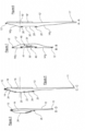
Figure 1 is a rear view of an ostomy appliance not falling within the scope of the claimed invention; -
Figure 2 is a front view of the ostomy appliance offigure 1 ; -
Figure 3 is a cross-sectional view through the plane D-D offigure 1 ; -
Figure 4 is a cross-sectional view through the plane C-C offigure 1 ; -
Figure 5 is a rear view of an ostomy appliance in accordance with the present invention; -
Figure 6 is a front view of an ostomy appliance in accordance with the present invention; -
Figure 7 is a cross-sectional view through the plane B-B offigure 5 ; -
Figure 8 is a cross-sectional view through the plane A-A offigure 5 ; -
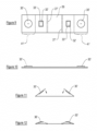
Figure 9 is a plan view of a component part of the present invention; and -
Figures 10 to 12 are side views of the component part offigure 9 is progressive stages of manufacture. - Referring firstly to
figures 1, 2 ,3 and 4 , these show an ostomy appliance, shown generally at 10, which does not fall within the scope of the claimed invention. The general construction of theostomy appliance 10 is similar to those well known in the art and in that sense it includes first 12 and second 14 walls connected to each other at or near their peripheries, for example by heat welding or using an adhesive. Thewalls opening 11 between thewalls - The
first wall 12 has a stoma-receivingopening 16 and is connected to a generallycircular flange 18 which is manufactured from the hydrocolloid material, for adhering theappliance 10 to a user around their stoma. The first 12 and second 14 walls define a waste collecting cavity (seen more clearly infigure 4 ). - The
ostomy appliance 10 includes aviewing portion 20 in thesecond wall 14 thereof through which the stoma receiving opening 16, and thus the stoma, can be viewed by a user. Theviewing portion 20 is generally circular although it should be appreciated that it could take many other forms so long as it is possible for the user to view at least a significant portion of the stoma-receivingopening 16. - The viewing portion is a transparent portion of an upper part of the
second wall 14 generally opposite the stoma receiving opening 16. In more detail, as can be seen fromfigures 1 ,3 and 4 , thesecond wall 14 includes, in an upper region thereof, anaperture 22 which defines theviewing portion 20 through which the stoma-receiving opening can be seen. Theaperture 22 is closed by a transparentadditional wall 24 which is connected to an exterior surface of thesecond wall 14 at or near itsperipheries 13, by alinear connection region 25, and around the aperture 22 (e.g. further heat welds or adhesives). - As best seen in
figure 1 theappliance 10 includes twofilters 30 which permit gas to escape from the space between thewalls gas filter 30 is positioned on an internally facing surface of thewall 24 and is adhered thereto adjacent an aperture (e.g. a slit) 31 in thewall 24. As can be seen fromfigure 1 theappliance 10 also includes a pair of gasflow path openings 32 each of which is positioned in the upper region (i.e. that which is covered by the wall 24) of thewall 14 and serves to provide a gas flow path between the main waste collecting cavity (betweenwalls 12, 14) and the cavity between thewalls - Now referring to
figures 5 to 8 these show an ostomy appliance 10' in accordance with the present invention. Feature similar to those of the ostomy appliance infigures 1 to 4 have been given the same reference numeral with the addition of a prime (') symbol and this will not be described in any further detail with regard to this embodiment. - The appliance of
figures 5 to 8 differs from the appliance offigures 1 to 4 in the arrangement and construction of the viewing portion 20' and the gas filters 30'. Rather than the viewing portion 20' being a circular portion, in this appliance it is the upper portion 14'b of the second wall 14'. This D-shaped portion 14'b of the wall 14' is transparent and thus it is possible for the user to view the stoma-receiving opening 16'. The remainder of the wall 14' is opaque as is the entire wall 12'. - In the ostomy appliance 10' the gas filters 30' are provided as part of a gas filter assembly 40' which in the present example forms an integral part of the second wall 14'. In other words the gas filter assembly 40' is connected to and positioned in between the upper 14'b and lower 14'a portions of the second wall 14'. The gas filter assembly 40' is therefore connected to the viewing portion 20'.
- The gas filter assembly 40' defines, in the present example, two gas filter chambers, each chamber containing one gas filter 30'. It should be appreciated, however, that fewer or more gas filter chambers could be provided and the number of gas filters within each chamber can be more than one. In the present example, as will become apparent hereinafter, the gas filter chambers are spaced from each other by a portion of wall 29'.
- Turning to
figures 9 through 12 , these show the gas filter assembly 40' in plan view (figure 9 ) and then in its progressive stages of manufacture (figures 10 through 12 ). As can be seen fromfigure 9 the gas assembly 40' is a strip/sheet of material (identical or similar to the material used for the walls of the appliance 10' - it must be liquid and gas impermeable) and is generally rectangular. Each gas chamber is defined by a folded end portion 41' of the sheet. Positioned either side of the central wall portion 29' is a portion of the sheet onto which the folded portion 41' is folded. This portion of the sheet includes a gas flow path 32' which in this example is covered by a gas permeable membrane 33'. As can be seen fromfigures 11 and 12 remote portions 41' of the sheet are folded back towards the central wall portion 29' where they are then adhered to the remainder of the sheet at linear connection zones 27'. As seen infigure 12 this provides a gas filter assembly 40' including a pair of gas filter chambers which are spaced from each other by the wall portion 29'. This component part is then connected to the upper transparent portion 14'b of the second wall 14' at lateral weld line 26' and to the lower portion 14'A of the wall 14' at the linear lateral weld line 26'. The gas filter assembly 40' thus becomes an integral part of the second wall 14' whilst permitting waste gases to exit from the main cavity (between the walls 12', 14'), through the gas chambers and to atmosphere. - When used in this specification and claims, the terms "comprises" and "comprising" and variations thereof mean that the specified features, steps or integers are included. The terms are not to be interpreted to exclude the presence of other features, steps or components.
- The features disclosed in the foregoing description, or the following claims, or the accompanying drawings, expressed in their specific forms or in terms of a means for performing the disclosed function, or a method or process for attaining the disclosed result, as appropriate, may, separately, or in any combination of such features, be utilised for realising the invention in diverse forms thereof.
Claims (11)
- An ostomy (10) appliance having:-First (12') and second (14') walls connected to each other at or near their peripheries, the first wall (12') having a stoma-receiving opening (16'); anda waste collecting cavity defined between the first (12') and second (14') walls,characterised in that the upper part (14'b) of the second wall (14') opposite the stoma-receiving opening (16') is transparent to provide a viewing portion (20') through which the stoma-receiving opening (16') can be viewed and a lower part (14'a) of the second wall (14') is opaque, and the upper (14'b) and lower (14'a) parts of the second wall (14') are separate flexible sheets which are connected to each other.
- An ostomy appliance according to claim 1 wherein said connection extends laterally across the appliance.
- An ostomy appliance according to any preceding claim wherein the appliance includes an outlet (11) positioned at a bottom thereof for permitting emptying of the waste collecting cavity, and wherein a portion of the second wall (14'a) positioned adjacent the outlet (11) is opaque.
- An ostomy appliance according to any preceding claim wherein the appliance includes a further wall (29') connected to the first (12') and second (14') walls at or near their peripheries, the further wall (29') including an opening or a transparent portion which is substantially aligned with the viewing portion (20') of the second wall (14').
- An ostomy appliance according to any preceding claim wherein:
the appliance includes a further viewing portion through which a lower portion of the waste collecting cavity can be viewed. - An ostomy appliance according to any preceding claim wherein a gas flow path (32') is provided from the waste collecting cavity though the second wall (14'), and if present, an intermediate wall (29'), to atmosphere, preferably wherein the gas flow path (32') includes one or more gas vents in the wall(s) of the appliance.
- An ostomy appliance according to claim 6 wherein the or each gas vent includes or is covered by a filter (30').
- An ostomy appliance according to any preceding claim wherein the appliance includes a gas filter assembly (40') supporting one or more gas filters (30'), wherein the assembly includes a pair of walls which are connected to each other, and wherein the gas filter assembly (40') is connected to the viewing portion (20') of the second wall (14'), preferably wherein the gas filter assembly (40') forms an integral part of the second wall (14').
- An ostomy appliance according to claim 8 wherein the gas filter assembly (40') defines two gas filter chambers, each chamber containing at least one gas filter (30'), preferably wherein the gas filter chambers are spaced from each other, preferably by a portion of wall (29').
- An ostomy appliance according to claim 8 or claim 9 wherein the gas filter assembly (40') is a single sheet of material, with each gas chamber being defined by a folded portion (41') of the sheet, preferably wherein each folded portion (41') is folded towards a central region of the assembly.
- An ostomy appliance according to claim 10 wherein a remote edge of each folded portion is connected to the remainder of the sheet to form the gas filter chamber, and preferably wherein the remote edge is heat welded in place.
Priority Applications (2)
| Application Number | Priority Date | Filing Date | Title |
|---|---|---|---|
| PL14702901.1T PL2950760T5 (en) | 2013-02-01 | 2014-01-28 | Ostomy appliance |
| SI201431785T SI2950760T2 (en) | 2013-02-01 | 2014-01-28 | Ostomy appliance |
Applications Claiming Priority (2)
| Application Number | Priority Date | Filing Date | Title |
|---|---|---|---|
| GB1301858.5A GB2510398B (en) | 2013-02-01 | 2013-02-01 | Ostomy appliance |
| PCT/GB2014/050212 WO2014118518A1 (en) | 2013-02-01 | 2014-01-28 | Ostomy appliance |
Publications (3)
| Publication Number | Publication Date |
|---|---|
| EP2950760A1 EP2950760A1 (en) | 2015-12-09 |
| EP2950760B1 EP2950760B1 (en) | 2021-02-24 |
| EP2950760B2 true EP2950760B2 (en) | 2023-12-20 |
Family
ID=47988598
Family Applications (1)
| Application Number | Title | Priority Date | Filing Date |
|---|---|---|---|
| EP14702901.1A Active EP2950760B2 (en) | 2013-02-01 | 2014-01-28 | Ostomy appliance |
Country Status (14)
| Country | Link |
|---|---|
| US (1) | US11045346B2 (en) |
| EP (1) | EP2950760B2 (en) |
| JP (2) | JP6640562B2 (en) |
| AU (1) | AU2014210928B2 (en) |
| CA (1) | CA2899989A1 (en) |
| CY (1) | CY1124014T1 (en) |
| DK (1) | DK2950760T4 (en) |
| GB (1) | GB2510398B (en) |
| LT (1) | LT2950760T (en) |
| NZ (1) | NZ710093A (en) |
| PL (1) | PL2950760T5 (en) |
| PT (1) | PT2950760T (en) |
| SI (1) | SI2950760T2 (en) |
| WO (1) | WO2014118518A1 (en) |
Families Citing this family (69)
| Publication number | Priority date | Publication date | Assignee | Title |
|---|---|---|---|---|
| US9314365B2 (en) | 2009-07-14 | 2016-04-19 | B. Braun Medical Sas | Ostomy port gas release mechanism |
| JP2015515905A (en) | 2012-05-10 | 2015-06-04 | スティマティックス ジーアイ リミテッド | Surgery instruments |
| CN105828752A (en) | 2013-05-09 | 2016-08-03 | 斯提马提克斯Gi有限公司 | Compact ostomy appliance |
| USD796029S1 (en) * | 2013-12-09 | 2017-08-29 | B. Braun Medical Sas | Colostomy appliance |
| US11376152B2 (en) | 2014-03-19 | 2022-07-05 | Purewick Corporation | Apparatus and methods for receiving discharged urine |
| US10390989B2 (en) | 2014-03-19 | 2019-08-27 | Purewick Corporation | Apparatus and methods for receiving discharged urine |
| US10952889B2 (en) | 2016-06-02 | 2021-03-23 | Purewick Corporation | Using wicking material to collect liquid for transport |
| US10226376B2 (en) | 2014-03-19 | 2019-03-12 | Purewick Corporation | Apparatus and methods for receiving discharged urine |
| US11806266B2 (en) | 2014-03-19 | 2023-11-07 | Purewick Corporation | Apparatus and methods for receiving discharged urine |
| US10376406B2 (en) | 2016-07-27 | 2019-08-13 | Purewick Corporation | Male urine collection device using wicking material |
| US10973678B2 (en) | 2016-07-27 | 2021-04-13 | Purewick Corporation | Apparatus and methods for receiving discharged urine |
| CN110612075B (en) | 2017-01-31 | 2022-09-09 | 普利维克公司 | Apparatus and method for receiving excreted urine |
| GB201715394D0 (en) * | 2017-09-22 | 2017-11-08 | Salts Healthcare Ltd | An ostomy appliance |
| US11771585B2 (en) | 2018-01-19 | 2023-10-03 | Ostovalve, Llc | Devices, systems and methods for regulating flow from a stoma on a patient |
| US12178738B2 (en) | 2018-01-19 | 2024-12-31 | Ostovalve Llc | Regulating flow from a stoma on a patient |
| WO2019212949A1 (en) | 2018-05-01 | 2019-11-07 | Purewick Corporation | Fluid collection devices, systems, and methods |
| CN112367949B (en) | 2018-05-01 | 2023-09-12 | 普利维克公司 | Fluid collection devices, related systems and related methods |
| CA3098680A1 (en) | 2018-05-01 | 2019-11-07 | Purewick Corporation | Fluid collection garments |
| KR102493455B1 (en) | 2018-05-01 | 2023-01-31 | 퓨어윅 코포레이션 | Fluid collection devices, related systems, and related methods |
| EP3787569B1 (en) | 2018-05-01 | 2025-07-16 | Purewick Corporation | Fluid collection devices and systems |
| KR102492111B1 (en) | 2018-05-01 | 2023-01-27 | 퓨어윅 코포레이션 | Fluid Collection Devices and Methods of Using The Same |
| USD1012280S1 (en) | 2018-11-30 | 2024-01-23 | B. Braun Medical Sas | Ostomy device assembly |
| WO2020256865A1 (en) | 2019-06-21 | 2020-12-24 | Purewick Corporation | Fluid collection devices including a base securement area, and related systems and methods |
| CN114375187A (en) | 2019-07-11 | 2022-04-19 | 普奥维克有限公司 | Fluid collection devices, systems, and methods |
| EP3999003B1 (en) | 2019-07-19 | 2024-05-01 | Purewick Corporation | Fluid collection devices including at least one shape memory material |
| CN114867435B (en) | 2019-10-28 | 2025-12-23 | 普利维克公司 | Fluid collection assembly including sample port |
| EP4084746B1 (en) | 2020-01-03 | 2025-04-02 | Purewick Corporation | Urine collection devices having a relatively wide portion and an elongated portion and related methods cross-reference to related applications |
| US12589022B2 (en) | 2020-03-19 | 2026-03-31 | Purewick Corporation | Fluid collection assemblies including one or more movement enhancing features |
| US12521288B2 (en) | 2020-03-26 | 2026-01-13 | Purewick Corporation | Multi-layer urine capture device and related methods |
| EP4344685B1 (en) | 2020-04-10 | 2025-06-11 | Purewick Corporation | Fluid collection assemblies including one or more leak prevention features |
| WO2021211599A1 (en) | 2020-04-17 | 2021-10-21 | Purewick Corporation | Female external catheter devices having a urethral cup, and related systems and methods |
| US12447042B2 (en) | 2020-04-17 | 2025-10-21 | Purewick Corporation | Fluid collection assemblies including a fluid impermeable barrier having a sump and a base |
| WO2021211729A1 (en) | 2020-04-17 | 2021-10-21 | Purewick Corporation | Fluid collection devices, systems, and methods securing a protruding portion in position for use |
| WO2021216422A1 (en) | 2020-04-20 | 2021-10-28 | Purewick Corporation | Fluid collection devices adjustable between a vacuum- based orientation and a gravity-based orientation, and related systems and methods |
| US12048643B2 (en) | 2020-05-27 | 2024-07-30 | Purewick Corporation | Fluid collection assemblies including at least one inflation device and methods and systems of using the same |
| USD967409S1 (en) | 2020-07-15 | 2022-10-18 | Purewick Corporation | Urine collection apparatus cover |
| WO2022031943A1 (en) | 2020-08-06 | 2022-02-10 | Purewick Corporation | A fluid collection system including a garment and a fluid collection device |
| US20220047410A1 (en) | 2020-08-11 | 2022-02-17 | Purewick Corporation | Fluid collection assemblies defining waist and leg openings |
| GB2598597B (en) * | 2020-09-03 | 2025-02-26 | Salts Healthcare Ltd | An ostomy appliance |
| US12521272B2 (en) | 2020-09-09 | 2026-01-13 | Purewick Corporation | Fluid collection devices, systems, and methods |
| US11801186B2 (en) | 2020-09-10 | 2023-10-31 | Purewick Corporation | Urine storage container handle and lid accessories |
| US12156792B2 (en) | 2020-09-10 | 2024-12-03 | Purewick Corporation | Fluid collection assemblies including at least one inflation device |
| US12042423B2 (en) | 2020-10-07 | 2024-07-23 | Purewick Corporation | Fluid collection systems including at least one tensioning element |
| US12208031B2 (en) | 2020-10-21 | 2025-01-28 | Purewick Corporation | Adapters for fluid collection devices |
| US12257174B2 (en) | 2020-10-21 | 2025-03-25 | Purewick Corporation | Fluid collection assemblies including at least one of a protrusion or at least one expandable material |
| US12440370B2 (en) | 2020-10-21 | 2025-10-14 | Purewick Corporation | Apparatus with compressible casing for receiving discharged urine |
| US12569365B2 (en) | 2020-10-21 | 2026-03-10 | Purewick Corporation | Fluid collection assemblies including at least one shape memory material disposed in the conduit |
| US12048644B2 (en) | 2020-11-03 | 2024-07-30 | Purewick Corporation | Apparatus for receiving discharged urine |
| US12070432B2 (en) | 2020-11-11 | 2024-08-27 | Purewick Corporation | Urine collection system including a flow meter and related methods |
| US12245967B2 (en) | 2020-11-18 | 2025-03-11 | Purewick Corporation | Fluid collection assemblies including an adjustable spine |
| US12599495B2 (en) | 2021-01-05 | 2026-04-14 | Purewick Corporation | Male external catheter with attachment interface configured to bias against penis |
| US12268627B2 (en) | 2021-01-06 | 2025-04-08 | Purewick Corporation | Fluid collection assemblies including at least one securement body |
| JP2024503636A (en) | 2021-01-07 | 2024-01-26 | ピュアウィック コーポレイション | Wheelchair-secure urine collection system and related methods |
| JP7500744B2 (en) | 2021-01-19 | 2024-06-17 | ピュアウィック コーポレイション | Variable Fluid Collection Devices, Systems, and Methods |
| US12178735B2 (en) | 2021-02-09 | 2024-12-31 | Purewick Corporation | Noise reduction for a urine suction system |
| CN116615162A (en) | 2021-02-26 | 2023-08-18 | 普奥维克有限公司 | Fluid collection device with reservoir between nozzle and barrier and related systems and methods |
| US12558472B2 (en) | 2021-03-05 | 2026-02-24 | Purewick Corporation | Portable fluid collection systems with storage and related methods |
| US12551385B2 (en) | 2021-03-05 | 2026-02-17 | Purewick Corporation | Fluid collection assembly including a tube having porous wicking material for improved fluid transport |
| US12458525B2 (en) | 2021-03-10 | 2025-11-04 | Purewick Corporation | Acoustic silencer for a urine suction system |
| US11938054B2 (en) | 2021-03-10 | 2024-03-26 | Purewick Corporation | Bodily waste and fluid collection with sacral pad |
| US12029677B2 (en) | 2021-04-06 | 2024-07-09 | Purewick Corporation | Fluid collection devices having a collection bag, and related systems and methods |
| US12233003B2 (en) | 2021-04-29 | 2025-02-25 | Purewick Corporation | Fluid collection assemblies including at least one length adjusting feature |
| US12251333B2 (en) | 2021-05-21 | 2025-03-18 | Purewick Corporation | Fluid collection assemblies including at least one inflation device and methods and systems of using the same |
| US12324767B2 (en) | 2021-05-24 | 2025-06-10 | Purewick Corporation | Fluid collection assembly including a customizable external support and related methods |
| US12150885B2 (en) | 2021-05-26 | 2024-11-26 | Purewick Corporation | Fluid collection system including a cleaning system and methods |
| US12575960B2 (en) | 2021-06-24 | 2026-03-17 | Purewick Corporation | Urine collection systems having one or more of volume, pressure, or flow indicators, and related methods |
| US12551366B2 (en) | 2021-08-02 | 2026-02-17 | Purewick Corporation | Fluid collection devices having multiple fluid collection regions, and related systems and methods |
| US12594062B2 (en) | 2021-09-08 | 2026-04-07 | Purewick Corporation | Fluid collection assemblies including an extension |
| AU2023258450B1 (en) | 2022-09-08 | 2023-12-14 | Hollister Incorporated | Ostomy pouch with viewing option feature |
Citations (1)
| Publication number | Priority date | Publication date | Assignee | Title |
|---|---|---|---|---|
| US20090234312A1 (en) † | 2007-04-24 | 2009-09-17 | O'toole Lois Diane | Ostomy Pouch |
Family Cites Families (29)
| Publication number | Priority date | Publication date | Assignee | Title |
|---|---|---|---|---|
| US3570490A (en) * | 1968-11-15 | 1971-03-16 | Atlantic Surgical Co Inc | Enterostomy pouch |
| US3780739A (en) * | 1971-12-07 | 1973-12-25 | M Frank | Drainage bag assembly with flow control for body fluids |
| US4219023A (en) * | 1978-05-23 | 1980-08-26 | Galindo Eugene R | Convex insert and ostomy bag structure |
| US4319571A (en) * | 1979-03-01 | 1982-03-16 | General Motors Corporation | Ostomy appliance |
| JP3772314B2 (en) * | 1996-01-12 | 2006-05-10 | アルケア株式会社 | Pouch drainage pouch |
| EP1294326B2 (en) * | 2000-06-28 | 2010-02-24 | Coloplast A/S | Method for welding components of a multi-layer construction |
| US6790200B2 (en) * | 2001-01-11 | 2004-09-14 | Marlen Manufacturing And Development Co., Inc. | Ostomy pouch and method of assembly |
| DK175390B1 (en) * | 2002-04-17 | 2004-09-20 | Coloplast As | Collection bag with improved recording means for a closure device |
| DK176425B1 (en) * | 2003-03-17 | 2008-02-04 | Coloplast As | An ostomy appliance |
| GB0409446D0 (en) * | 2004-04-28 | 2004-06-02 | Smith & Nephew | Apparatus |
| RU2008151160A (en) * | 2006-05-24 | 2010-06-27 | Колопласт А/С (Dk) | KALA COLLECTION KIT |
| US20070282271A1 (en) * | 2006-05-31 | 2007-12-06 | Kaplan Michael D | Ostomy and percutaneous catheter protective and affixation device |
| JP2010523276A (en) * | 2007-04-09 | 2010-07-15 | ブリストル−マイヤーズ スクイブ カンパニー | Adhesive body wear device for stoma orthosis |
| US20080269700A1 (en) * | 2007-04-24 | 2008-10-30 | O'toole Lois Diane | Ostomy pouch |
| US20080269699A1 (en) | 2007-04-24 | 2008-10-30 | O'toole Lois Diane | Ostomy pouch |
| JP2010528719A (en) * | 2007-06-01 | 2010-08-26 | マーレン マニュファクチュアリング アンド デヴェロップメント カンパニー インコーポレイテッド | Visible ostomy pouch cover |
| EP2187846B1 (en) * | 2007-08-10 | 2015-05-06 | Coloplast A/S | A faecal management device |
| HRP20171056T1 (en) * | 2008-11-19 | 2017-10-06 | Convatec Technologies Inc. | Ostomy appliance with moldable adhesive |
| US8211073B2 (en) * | 2009-06-17 | 2012-07-03 | Hollister Incorporated | Ostomy faceplate having moldable adhesive wafer with diminishing surface undulations |
| US10130506B2 (en) * | 2010-03-02 | 2018-11-20 | Ostosolutions, LLC | Closure system for an ostomy pouch and related methods |
| EP2754426B1 (en) * | 2010-06-04 | 2015-08-19 | Coloplast A/S | An ostomy appliance with a filter construction |
| RU2565102C2 (en) * | 2010-06-04 | 2015-10-20 | Колопласт А/С | Filter with extended element |
| EP2510910A1 (en) * | 2011-04-12 | 2012-10-17 | Hollister Incorporated | An ostomy pouch |
| US20130035653A1 (en) * | 2011-08-02 | 2013-02-07 | Cryovac, Inc. | Ostomy Pouch Comprising Absorbent Material |
| EP2794266A1 (en) * | 2011-12-22 | 2014-10-29 | Avery Dennison Corporation | Flexible barrier films containing cyclic olefins |
| EP2668935A1 (en) * | 2012-05-31 | 2013-12-04 | Hollister Incorporated | An ostomy pouch |
| CN104661621B (en) * | 2012-08-01 | 2016-11-16 | 西蒙·德贝尔 | Ostomy Treatment Devices |
| JP6783519B2 (en) * | 2012-11-20 | 2020-11-11 | コンバテック・テクノロジーズ・インコーポレイテッドConvatec Technologies Inc | Improvement of One Piece Ostomy Pouch |
| US9956110B2 (en) * | 2013-06-22 | 2018-05-01 | Jezekiel Ben-Arie | Washable ostomy pouch II |
-
2013
- 2013-02-01 GB GB1301858.5A patent/GB2510398B/en active Active
-
2014
- 2014-01-28 DK DK14702901.1T patent/DK2950760T4/en active
- 2014-01-28 WO PCT/GB2014/050212 patent/WO2014118518A1/en not_active Ceased
- 2014-01-28 PT PT147029011T patent/PT2950760T/en unknown
- 2014-01-28 LT LTEP14702901.1T patent/LT2950760T/en unknown
- 2014-01-28 AU AU2014210928A patent/AU2014210928B2/en not_active Ceased
- 2014-01-28 EP EP14702901.1A patent/EP2950760B2/en active Active
- 2014-01-28 SI SI201431785T patent/SI2950760T2/en unknown
- 2014-01-28 US US14/765,219 patent/US11045346B2/en not_active Expired - Fee Related
- 2014-01-28 PL PL14702901.1T patent/PL2950760T5/en unknown
- 2014-01-28 CA CA2899989A patent/CA2899989A1/en not_active Abandoned
- 2014-01-28 NZ NZ710093A patent/NZ710093A/en not_active IP Right Cessation
- 2014-01-28 JP JP2015555788A patent/JP6640562B2/en not_active Expired - Fee Related
-
2018
- 2018-09-10 JP JP2018168983A patent/JP2018187508A/en active Pending
-
2021
- 2021-04-12 CY CY20211100312T patent/CY1124014T1/en unknown
Patent Citations (1)
| Publication number | Priority date | Publication date | Assignee | Title |
|---|---|---|---|---|
| US20090234312A1 (en) † | 2007-04-24 | 2009-09-17 | O'toole Lois Diane | Ostomy Pouch |
Also Published As
| Publication number | Publication date |
|---|---|
| EP2950760B1 (en) | 2021-02-24 |
| US20150359657A1 (en) | 2015-12-17 |
| PT2950760T (en) | 2021-05-28 |
| LT2950760T (en) | 2021-04-12 |
| GB2510398A (en) | 2014-08-06 |
| NZ710093A (en) | 2017-12-22 |
| AU2014210928B2 (en) | 2018-02-01 |
| PL2950760T5 (en) | 2024-02-26 |
| US11045346B2 (en) | 2021-06-29 |
| JP2016504952A (en) | 2016-02-18 |
| DK2950760T3 (en) | 2021-03-08 |
| DK2950760T4 (en) | 2024-02-12 |
| SI2950760T1 (en) | 2021-04-30 |
| WO2014118518A1 (en) | 2014-08-07 |
| GB2510398B (en) | 2017-10-25 |
| PL2950760T3 (en) | 2021-06-14 |
| JP2018187508A (en) | 2018-11-29 |
| GB201301858D0 (en) | 2013-03-20 |
| AU2014210928A1 (en) | 2015-08-06 |
| SI2950760T2 (en) | 2024-03-29 |
| CY1124014T1 (en) | 2022-05-27 |
| CA2899989A1 (en) | 2014-08-07 |
| EP2950760A1 (en) | 2015-12-09 |
| JP6640562B2 (en) | 2020-02-05 |
Similar Documents
| Publication | Publication Date | Title |
|---|---|---|
| EP2950760B2 (en) | Ostomy appliance | |
| US10478330B2 (en) | Ostomy appliance | |
| EP3684300B1 (en) | An ostomy appliance | |
| AU2025203771B2 (en) | An ostomy appliance | |
| NZ791565A (en) | An ostomy appliance |
Legal Events
| Date | Code | Title | Description |
|---|---|---|---|
| PUAI | Public reference made under article 153(3) epc to a published international application that has entered the european phase |
Free format text: ORIGINAL CODE: 0009012 |
|
| 17P | Request for examination filed |
Effective date: 20150625 |
|
| AK | Designated contracting states |
Kind code of ref document: A1 Designated state(s): AL AT BE BG CH CY CZ DE DK EE ES FI FR GB GR HR HU IE IS IT LI LT LU LV MC MK MT NL NO PL PT RO RS SE SI SK SM TR |
|
| AX | Request for extension of the european patent |
Extension state: BA ME |
|
| DAX | Request for extension of the european patent (deleted) | ||
| STAA | Information on the status of an ep patent application or granted ep patent |
Free format text: STATUS: EXAMINATION IS IN PROGRESS |
|
| 17Q | First examination report despatched |
Effective date: 20170321 |
|
| GRAP | Despatch of communication of intention to grant a patent |
Free format text: ORIGINAL CODE: EPIDOSNIGR1 |
|
| STAA | Information on the status of an ep patent application or granted ep patent |
Free format text: STATUS: GRANT OF PATENT IS INTENDED |
|
| INTG | Intention to grant announced |
Effective date: 20200406 |
|
| RAP1 | Party data changed (applicant data changed or rights of an application transferred) |
Owner name: SALTS HEALTHCARE LIMITED |
|
| GRAJ | Information related to disapproval of communication of intention to grant by the applicant or resumption of examination proceedings by the epo deleted |
Free format text: ORIGINAL CODE: EPIDOSDIGR1 |
|
| STAA | Information on the status of an ep patent application or granted ep patent |
Free format text: STATUS: EXAMINATION IS IN PROGRESS |
|
| INTC | Intention to grant announced (deleted) | ||
| GRAP | Despatch of communication of intention to grant a patent |
Free format text: ORIGINAL CODE: EPIDOSNIGR1 |
|
| STAA | Information on the status of an ep patent application or granted ep patent |
Free format text: STATUS: GRANT OF PATENT IS INTENDED |
|
| INTG | Intention to grant announced |
Effective date: 20201001 |
|
| GRAS | Grant fee paid |
Free format text: ORIGINAL CODE: EPIDOSNIGR3 |
|
| GRAA | (expected) grant |
Free format text: ORIGINAL CODE: 0009210 |
|
| STAA | Information on the status of an ep patent application or granted ep patent |
Free format text: STATUS: THE PATENT HAS BEEN GRANTED |
|
| AK | Designated contracting states |
Kind code of ref document: B1 Designated state(s): AL AT BE BG CH CY CZ DE DK EE ES FI FR GB GR HR HU IE IS IT LI LT LU LV MC MK MT NL NO PL PT RO RS SE SI SK SM TR |
|
| REG | Reference to a national code |
Ref country code: GB Ref legal event code: FG4D |
|
| REG | Reference to a national code |
Ref country code: CH Ref legal event code: EP |
|
| REG | Reference to a national code |
Ref country code: DK Ref legal event code: T3 Effective date: 20210301 |
|
| REG | Reference to a national code |
Ref country code: DE Ref legal event code: R096 Ref document number: 602014075089 Country of ref document: DE |
|
| REG | Reference to a national code |
Ref country code: AT Ref legal event code: REF Ref document number: 1363550 Country of ref document: AT Kind code of ref document: T Effective date: 20210315 |
|
| REG | Reference to a national code |
Ref country code: IE Ref legal event code: FG4D |
|
| REG | Reference to a national code |
Ref country code: CH Ref legal event code: NV Representative=s name: ISLER AND PEDRAZZINI AG, CH Ref country code: NL Ref legal event code: FP |
|
| REG | Reference to a national code |
Ref country code: SK Ref legal event code: T3 Ref document number: E 36546 Country of ref document: SK |
|
| REG | Reference to a national code |
Ref country code: NO Ref legal event code: T2 Effective date: 20210224 |
|
| REG | Reference to a national code |
Ref country code: GR Ref legal event code: EP Ref document number: 20210400967 Country of ref document: GR Effective date: 20210519 |
|
| REG | Reference to a national code |
Ref country code: PT Ref legal event code: SC4A Ref document number: 2950760 Country of ref document: PT Date of ref document: 20210528 Kind code of ref document: T Free format text: AVAILABILITY OF NATIONAL TRANSLATION Effective date: 20210524 |
|
| REG | Reference to a national code |
Ref country code: SE Ref legal event code: TRGR |
|
| PG25 | Lapsed in a contracting state [announced via postgrant information from national office to epo] |
Ref country code: HR Free format text: LAPSE BECAUSE OF FAILURE TO SUBMIT A TRANSLATION OF THE DESCRIPTION OR TO PAY THE FEE WITHIN THE PRESCRIBED TIME-LIMIT Effective date: 20210224 Ref country code: FI Free format text: LAPSE BECAUSE OF FAILURE TO SUBMIT A TRANSLATION OF THE DESCRIPTION OR TO PAY THE FEE WITHIN THE PRESCRIBED TIME-LIMIT Effective date: 20210224 |
|
| PG25 | Lapsed in a contracting state [announced via postgrant information from national office to epo] |
Ref country code: LV Free format text: LAPSE BECAUSE OF FAILURE TO SUBMIT A TRANSLATION OF THE DESCRIPTION OR TO PAY THE FEE WITHIN THE PRESCRIBED TIME-LIMIT Effective date: 20210224 Ref country code: RS Free format text: LAPSE BECAUSE OF FAILURE TO SUBMIT A TRANSLATION OF THE DESCRIPTION OR TO PAY THE FEE WITHIN THE PRESCRIBED TIME-LIMIT Effective date: 20210224 |
|
| PG25 | Lapsed in a contracting state [announced via postgrant information from national office to epo] |
Ref country code: IS Free format text: LAPSE BECAUSE OF FAILURE TO SUBMIT A TRANSLATION OF THE DESCRIPTION OR TO PAY THE FEE WITHIN THE PRESCRIBED TIME-LIMIT Effective date: 20210624 |
|
| PG25 | Lapsed in a contracting state [announced via postgrant information from national office to epo] |
Ref country code: SM Free format text: LAPSE BECAUSE OF FAILURE TO SUBMIT A TRANSLATION OF THE DESCRIPTION OR TO PAY THE FEE WITHIN THE PRESCRIBED TIME-LIMIT Effective date: 20210224 Ref country code: EE Free format text: LAPSE BECAUSE OF FAILURE TO SUBMIT A TRANSLATION OF THE DESCRIPTION OR TO PAY THE FEE WITHIN THE PRESCRIBED TIME-LIMIT Effective date: 20210224 |
|
| REG | Reference to a national code |
Ref country code: DE Ref legal event code: R026 Ref document number: 602014075089 Country of ref document: DE |
|
| PLBI | Opposition filed |
Free format text: ORIGINAL CODE: 0009260 |
|
| PG25 | Lapsed in a contracting state [announced via postgrant information from national office to epo] |
Ref country code: RO Free format text: LAPSE BECAUSE OF FAILURE TO SUBMIT A TRANSLATION OF THE DESCRIPTION OR TO PAY THE FEE WITHIN THE PRESCRIBED TIME-LIMIT Effective date: 20210224 Ref country code: ES Free format text: LAPSE BECAUSE OF FAILURE TO SUBMIT A TRANSLATION OF THE DESCRIPTION OR TO PAY THE FEE WITHIN THE PRESCRIBED TIME-LIMIT Effective date: 20210224 |
|
| PLAX | Notice of opposition and request to file observation + time limit sent |
Free format text: ORIGINAL CODE: EPIDOSNOBS2 |
|
| 26 | Opposition filed |
Opponent name: HOLLISTER INCORPORATED Effective date: 20211111 |
|
| PG25 | Lapsed in a contracting state [announced via postgrant information from national office to epo] |
Ref country code: AL Free format text: LAPSE BECAUSE OF FAILURE TO SUBMIT A TRANSLATION OF THE DESCRIPTION OR TO PAY THE FEE WITHIN THE PRESCRIBED TIME-LIMIT Effective date: 20210224 |
|
| PLBB | Reply of patent proprietor to notice(s) of opposition received |
Free format text: ORIGINAL CODE: EPIDOSNOBS3 |
|
| PG25 | Lapsed in a contracting state [announced via postgrant information from national office to epo] |
Ref country code: IT Free format text: LAPSE BECAUSE OF FAILURE TO SUBMIT A TRANSLATION OF THE DESCRIPTION OR TO PAY THE FEE WITHIN THE PRESCRIBED TIME-LIMIT Effective date: 20210224 |
|
| PG25 | Lapsed in a contracting state [announced via postgrant information from national office to epo] |
Ref country code: IS Free format text: LAPSE BECAUSE OF FAILURE TO SUBMIT A TRANSLATION OF THE DESCRIPTION OR TO PAY THE FEE WITHIN THE PRESCRIBED TIME-LIMIT Effective date: 20210624 |
|
| PG25 | Lapsed in a contracting state [announced via postgrant information from national office to epo] |
Ref country code: MC Free format text: LAPSE BECAUSE OF FAILURE TO SUBMIT A TRANSLATION OF THE DESCRIPTION OR TO PAY THE FEE WITHIN THE PRESCRIBED TIME-LIMIT Effective date: 20210224 |
|
| PG25 | Lapsed in a contracting state [announced via postgrant information from national office to epo] |
Ref country code: LU Free format text: LAPSE BECAUSE OF NON-PAYMENT OF DUE FEES Effective date: 20220128 |
|
| REG | Reference to a national code |
Ref country code: AT Ref legal event code: UEP Ref document number: 1363550 Country of ref document: AT Kind code of ref document: T Effective date: 20210224 |
|
| P01 | Opt-out of the competence of the unified patent court (upc) registered |
Effective date: 20230509 |
|
| PUAH | Patent maintained in amended form |
Free format text: ORIGINAL CODE: 0009272 |
|
| STAA | Information on the status of an ep patent application or granted ep patent |
Free format text: STATUS: PATENT MAINTAINED AS AMENDED |
|
| 27A | Patent maintained in amended form |
Effective date: 20231220 |
|
| AK | Designated contracting states |
Kind code of ref document: B2 Designated state(s): AL AT BE BG CH CY CZ DE DK EE ES FI FR GB GR HR HU IE IS IT LI LT LU LV MC MK MT NL NO PL PT RO RS SE SI SK SM TR |
|
| REG | Reference to a national code |
Ref country code: DE Ref legal event code: R102 Ref document number: 602014075089 Country of ref document: DE |
|
| REG | Reference to a national code |
Ref country code: DK Ref legal event code: T4 Effective date: 20240208 |
|
| REG | Reference to a national code |
Ref country code: NL Ref legal event code: FP |
|
| REG | Reference to a national code |
Ref country code: SK Ref legal event code: T5 Ref document number: E 36546 Country of ref document: SK |
|
| REG | Reference to a national code |
Ref country code: SE Ref legal event code: RPEO |
|
| PG25 | Lapsed in a contracting state [announced via postgrant information from national office to epo] |
Ref country code: HU Free format text: LAPSE BECAUSE OF FAILURE TO SUBMIT A TRANSLATION OF THE DESCRIPTION OR TO PAY THE FEE WITHIN THE PRESCRIBED TIME-LIMIT; INVALID AB INITIO Effective date: 20140128 |
|
| REG | Reference to a national code |
Ref country code: GR Ref legal event code: EP Ref document number: 20240400626 Country of ref document: GR Effective date: 20240410 |
|
| PG25 | Lapsed in a contracting state [announced via postgrant information from national office to epo] |
Ref country code: MK Free format text: LAPSE BECAUSE OF FAILURE TO SUBMIT A TRANSLATION OF THE DESCRIPTION OR TO PAY THE FEE WITHIN THE PRESCRIBED TIME-LIMIT Effective date: 20210224 |
|
| PGFP | Annual fee paid to national office [announced via postgrant information from national office to epo] |
Ref country code: MT Payment date: 20241226 Year of fee payment: 12 |
|
| PGFP | Annual fee paid to national office [announced via postgrant information from national office to epo] |
Ref country code: PT Payment date: 20250116 Year of fee payment: 12 |
|
| PGFP | Annual fee paid to national office [announced via postgrant information from national office to epo] |
Ref country code: BG Payment date: 20250123 Year of fee payment: 12 |
|
| PGFP | Annual fee paid to national office [announced via postgrant information from national office to epo] |
Ref country code: SI Payment date: 20250116 Year of fee payment: 12 Ref country code: CH Payment date: 20250201 Year of fee payment: 12 Ref country code: GR Payment date: 20250122 Year of fee payment: 12 |
|
| PGFP | Annual fee paid to national office [announced via postgrant information from national office to epo] |
Ref country code: CZ Payment date: 20250120 Year of fee payment: 12 Ref country code: PL Payment date: 20250117 Year of fee payment: 12 |
|
| PGFP | Annual fee paid to national office [announced via postgrant information from national office to epo] |
Ref country code: SK Payment date: 20250122 Year of fee payment: 12 |
|
| PGFP | Annual fee paid to national office [announced via postgrant information from national office to epo] |
Ref country code: CY Payment date: 20250108 Year of fee payment: 12 |
|
| PG25 | Lapsed in a contracting state [announced via postgrant information from national office to epo] |
Ref country code: TR Free format text: LAPSE BECAUSE OF FAILURE TO SUBMIT A TRANSLATION OF THE DESCRIPTION OR TO PAY THE FEE WITHIN THE PRESCRIBED TIME-LIMIT Effective date: 20210224 |
|
| PGFP | Annual fee paid to national office [announced via postgrant information from national office to epo] |
Ref country code: GB Payment date: 20251230 Year of fee payment: 13 |
|
| REG | Reference to a national code |
Ref country code: CH Ref legal event code: U11 Free format text: ST27 STATUS EVENT CODE: U-0-0-U10-U11 (AS PROVIDED BY THE NATIONAL OFFICE) Effective date: 20260201 |
|
| PGFP | Annual fee paid to national office [announced via postgrant information from national office to epo] |
Ref country code: NL Payment date: 20260121 Year of fee payment: 13 |
|
| REG | Reference to a national code |
Ref country code: AT Ref legal event code: UEP Ref document number: 1363550 Country of ref document: AT Kind code of ref document: T Effective date: 20231220 |
|
| PGFP | Annual fee paid to national office [announced via postgrant information from national office to epo] |
Ref country code: SE Payment date: 20260121 Year of fee payment: 13 |
|
| PGFP | Annual fee paid to national office [announced via postgrant information from national office to epo] |
Ref country code: LT Payment date: 20260113 Year of fee payment: 13 |
|
| PGFP | Annual fee paid to national office [announced via postgrant information from national office to epo] |
Ref country code: DE Payment date: 20260121 Year of fee payment: 13 Ref country code: DK Payment date: 20260126 Year of fee payment: 13 Ref country code: NO Payment date: 20260123 Year of fee payment: 13 Ref country code: IE Payment date: 20260122 Year of fee payment: 13 |
|
| PGFP | Annual fee paid to national office [announced via postgrant information from national office to epo] |
Ref country code: AT Payment date: 20260122 Year of fee payment: 13 |
|
| PGFP | Annual fee paid to national office [announced via postgrant information from national office to epo] |
Ref country code: BE Payment date: 20260121 Year of fee payment: 13 |
|
| PGFP | Annual fee paid to national office [announced via postgrant information from national office to epo] |
Ref country code: FR Payment date: 20260123 Year of fee payment: 13 |