EP2950529B1 - Video image storage method and apparatus - Google Patents
Video image storage method and apparatus Download PDFInfo
- Publication number
- EP2950529B1 EP2950529B1 EP14848931.3A EP14848931A EP2950529B1 EP 2950529 B1 EP2950529 B1 EP 2950529B1 EP 14848931 A EP14848931 A EP 14848931A EP 2950529 B1 EP2950529 B1 EP 2950529B1
- Authority
- EP
- European Patent Office
- Prior art keywords
- frame rate
- confidence value
- image
- target encoding
- encoding frame
- Prior art date
- Legal status (The legal status is an assumption and is not a legal conclusion. Google has not performed a legal analysis and makes no representation as to the accuracy of the status listed.)
- Active
Links
Images
Classifications
-
- H—ELECTRICITY
- H04—ELECTRIC COMMUNICATION TECHNIQUE
- H04N—PICTORIAL COMMUNICATION, e.g. TELEVISION
- H04N5/00—Details of television systems
- H04N5/76—Television signal recording
- H04N5/91—Television signal processing therefor
- H04N5/915—Television signal processing therefor for field- or frame-skip recording or reproducing
-
- H—ELECTRICITY
- H04—ELECTRIC COMMUNICATION TECHNIQUE
- H04N—PICTORIAL COMMUNICATION, e.g. TELEVISION
- H04N5/00—Details of television systems
- H04N5/76—Television signal recording
- H04N5/91—Television signal processing therefor
-
- G—PHYSICS
- G06—COMPUTING OR CALCULATING; COUNTING
- G06V—IMAGE OR VIDEO RECOGNITION OR UNDERSTANDING
- G06V20/00—Scenes; Scene-specific elements
- G06V20/50—Context or environment of the image
- G06V20/52—Surveillance or monitoring of activities, e.g. for recognising suspicious objects
-
- H—ELECTRICITY
- H04—ELECTRIC COMMUNICATION TECHNIQUE
- H04N—PICTORIAL COMMUNICATION, e.g. TELEVISION
- H04N19/00—Methods or arrangements for coding, decoding, compressing or decompressing digital video signals
- H04N19/10—Methods or arrangements for coding, decoding, compressing or decompressing digital video signals using adaptive coding
- H04N19/102—Methods or arrangements for coding, decoding, compressing or decompressing digital video signals using adaptive coding characterised by the element, parameter or selection affected or controlled by the adaptive coding
- H04N19/132—Sampling, masking or truncation of coding units, e.g. adaptive resampling, frame skipping, frame interpolation or high-frequency transform coefficient masking
-
- H—ELECTRICITY
- H04—ELECTRIC COMMUNICATION TECHNIQUE
- H04N—PICTORIAL COMMUNICATION, e.g. TELEVISION
- H04N19/00—Methods or arrangements for coding, decoding, compressing or decompressing digital video signals
- H04N19/10—Methods or arrangements for coding, decoding, compressing or decompressing digital video signals using adaptive coding
- H04N19/134—Methods or arrangements for coding, decoding, compressing or decompressing digital video signals using adaptive coding characterised by the element, parameter or criterion affecting or controlling the adaptive coding
- H04N19/136—Incoming video signal characteristics or properties
-
- H—ELECTRICITY
- H04—ELECTRIC COMMUNICATION TECHNIQUE
- H04N—PICTORIAL COMMUNICATION, e.g. TELEVISION
- H04N19/00—Methods or arrangements for coding, decoding, compressing or decompressing digital video signals
- H04N19/10—Methods or arrangements for coding, decoding, compressing or decompressing digital video signals using adaptive coding
- H04N19/134—Methods or arrangements for coding, decoding, compressing or decompressing digital video signals using adaptive coding characterised by the element, parameter or criterion affecting or controlling the adaptive coding
- H04N19/146—Data rate or code amount at the encoder output
-
- H—ELECTRICITY
- H04—ELECTRIC COMMUNICATION TECHNIQUE
- H04N—PICTORIAL COMMUNICATION, e.g. TELEVISION
- H04N19/00—Methods or arrangements for coding, decoding, compressing or decompressing digital video signals
- H04N19/10—Methods or arrangements for coding, decoding, compressing or decompressing digital video signals using adaptive coding
- H04N19/169—Methods or arrangements for coding, decoding, compressing or decompressing digital video signals using adaptive coding characterised by the coding unit, i.e. the structural portion or semantic portion of the video signal being the object or the subject of the adaptive coding
- H04N19/17—Methods or arrangements for coding, decoding, compressing or decompressing digital video signals using adaptive coding characterised by the coding unit, i.e. the structural portion or semantic portion of the video signal being the object or the subject of the adaptive coding the unit being an image region, e.g. an object
- H04N19/172—Methods or arrangements for coding, decoding, compressing or decompressing digital video signals using adaptive coding characterised by the coding unit, i.e. the structural portion or semantic portion of the video signal being the object or the subject of the adaptive coding the unit being an image region, e.g. an object the region being a picture, frame or field
-
- H—ELECTRICITY
- H04—ELECTRIC COMMUNICATION TECHNIQUE
- H04N—PICTORIAL COMMUNICATION, e.g. TELEVISION
- H04N19/00—Methods or arrangements for coding, decoding, compressing or decompressing digital video signals
- H04N19/10—Methods or arrangements for coding, decoding, compressing or decompressing digital video signals using adaptive coding
- H04N19/169—Methods or arrangements for coding, decoding, compressing or decompressing digital video signals using adaptive coding characterised by the coding unit, i.e. the structural portion or semantic portion of the video signal being the object or the subject of the adaptive coding
- H04N19/177—Methods or arrangements for coding, decoding, compressing or decompressing digital video signals using adaptive coding characterised by the coding unit, i.e. the structural portion or semantic portion of the video signal being the object or the subject of the adaptive coding the unit being a group of pictures [GOP]
-
- H—ELECTRICITY
- H04—ELECTRIC COMMUNICATION TECHNIQUE
- H04N—PICTORIAL COMMUNICATION, e.g. TELEVISION
- H04N9/00—Details of colour television systems
- H04N9/79—Processing of colour television signals in connection with recording
- H04N9/80—Transformation of the television signal for recording, e.g. modulation, frequency changing; Inverse transformation for playback
- H04N9/804—Transformation of the television signal for recording, e.g. modulation, frequency changing; Inverse transformation for playback involving pulse code modulation of the colour picture signal components
- H04N9/8042—Transformation of the television signal for recording, e.g. modulation, frequency changing; Inverse transformation for playback involving pulse code modulation of the colour picture signal components involving data reduction
Definitions
- the present disclosure relates to video processing technologies, and more particularly, to a method and device for storing video images.
- monitoring equipment such as camera
- HD high definition
- the motion detecting or intelligent analysis technologies may be employed, to analyze whether a focused-on target exists in a video, and output a determination result about "yes” or "no".
- the determination result is "yes”
- US 2007/0189728A1 discloses a method of recording and reproducing surveillance images in a Digital Video Recorder (DVR).
- a recording speed such as a frame rate for surveillance images are controlled according to extent of motion of subjects in the surveillance detected through prediction between neighboring frames, and information about the controlled frame rates and information about time at which the frame rate is used may be managed and recorded in an associated manner.
- US 2007/0217765 A1 discloses the following technical solution.
- the channel in which the event occurs is set as an event CH and normal channels are set as normal CH.
- a processing is divided in accordance with a situation at that time into a frame rate changing processing of the event CH, a frame rate changing processing of the normal CH and the event CH and a changing processing that changes the frame rate of the event CH within a possible range.
- US 6591014B1 provides an apparatus for coding a moving picture while coding a part of frames of the moving picture into intra-frames (I-pictures), a part of frames sandwiched between contiguous intra-frames into forward predictive frames (P-pictures), and frames sandwiched between a forward predictive frame and another forward predictive frame or an intra-frame into a bidirectionally predictive frames (B-pictures), comprising: a determining means for determining the number of B-pictures between a P-picture and another P-picture or an I-picture based on an output frame rate and a substantial frame rate which is defined as the number of pictures capable of being processed per unit time by the apparatus provided that only I-pictures and P-pictures are coded; and a coding means for coding the B-pictures by treating the B-pictures as frames with no differential data.
- I-pictures intra-frames
- P-pictures forward predictive frames
- B-pictures bidirectionally predictive frames
- the present disclosure provides a method and device for storing video image, so as to improve adaptive capability and availability of a system.
- a method for storing a video image including:
- a device for storing a video image including a first processing module and a second processing module, wherein the first processing module is to generate a confidence value after receiving M frames of an image each time, and transmitting the confidence value to the second processing module, wherein M is a positive integer, the confidence value is a rational number greater than or equal to 0, a greater confidence value denotes a greater probability for a focused-on target exists in the image; and after receiving N frames of the image each time, the second processing module is to determine a target encoding frame rate based on the confidence value latest generated and a mapping relationship curve between confidence value and target encoding frame rate, encoding and recording the N frames of the image based on the determined target encoding frame rate, wherein N is a positive integer.
- the target encoding frame rate may be continuously adjusted based on confidence value. And then, encoding and recording may be executed, based on the adjusted target encoding frame rate, so as to avoid influence brought by misjudgment and missing judgment in the prior art to the largest extent, and improve adaptive capability and availability of system.
- the present disclosure provides a technical solution for storing a video image.
- FIG.1 is a flowchart illustrating a method for storing a video image, in accordance with an example of the present disclosure. As shown in FIG.1 , the method may include the following blocks 11-12.
- the confidence value is a rational number located in [T min , T max ]. Generally, T min is greater than or equal to 0. Greater confidence value denotes greater probability for a focused-on target exists in an image.
- T min when the value of T min is 0, it denotes that a focused-on target does not exist in an image.
- T max When the value of T max is 100, it denotes that a focused-on target exists in an image.
- Different values in 0 ⁇ 100 denote different possibilities for a focused-on target exists in an image.
- a confidence value may be generated for each frame of image, that is, a confidence value may be generated after passing every frame of image.
- a confidence value may also be generated after passing multiple frames of image each time. For example, when original image frame rate is 25 frames per second, a confidence value may be generated after passing 25 frames of image each time.
- the confidence value may be generated by adopting motion detecting or intelligent analysis technologies.
- the motion detecting technologies are generally applied to a fixed scene, and may obtain relevant information, such as area moved in a picture, moving range, and so on, by analyzing two adjacent frames of image, or analyzing multiple frames of image.
- the intelligent analysis technologies may analyze suspicious event behavior in a picture, and so on, by performing a background modeling, a target segmentation, a trajectory tracking to a scene image.
- Specific implementation modes of block 12 may be different, based on different values of N, which will be respectively described in the following.
- values of N and M may be the same, or may be different.
- the following processes may be respectively performed to each frame of image.
- K+1 ⁇ X encoding and recording are not performed to the frame of image, and add 1 to the value of K, that is, K++.
- the original image frame rate is 25 frames per second
- N 25
- the target encoding frame rate is 12.5 frames per second
- the foregoing processing mode may be referred to as a first processing mode.
- the processing mode may be referred to as a second processing mode.
- the first processing mode may be achieved.
- the technical solutions of the present disclosure also put forward the following. Determine actual bit stream R and expected bit stream S, every time a predetermined condition is met. Determine whether it is necessary to adjust the mapping relationship curve based on R and S. When determining that it is necessary to adjust the mapping relationship curve based on R and S, adjust the mapping relationship curve.
- the abovementioned adjusting may include as follows.
- S>R increase the target encoding frame rate corresponding to the confidence value between T min and T max .
- S ⁇ R decrease the target encoding frame rate corresponding to the confidence value between T min and T max .
- a value obtained after dividing consumed storage capacity by storage time may be calculated, and a calculation result may be taken as R.
- the consumed storage capacity in storage space is xGB, in which videos of y days are stored, and then the value of x/y may be taken as R.
- R may reflect actual consumption rate of storage statistically.
- a result obtained after dividing un-consumed storage capacity by expected storage time may also be calculated, and the calculation result may be taken as S.
- the remaining (e.g., not-consumed) storage capacity in storage space is aGB
- expected storage time is b days
- the value of a/b may be taken as S.
- S may reflect consumption rate of storage expecting to be achieved.
- the expected storage time may be set manually, and specific value of the expected storage time may be determined based on actual requirements.
- the unit of foregoing storage time is day, which may be also hour, second, and so on.
- other modes occurred to persons having ordinary skill in the art may also be used to determined R and S, which are not limited to the foregoing modes.
- values of R and S may be determined once again. Alternatively, expect for the first time, R may be determined subsequently, and S may be calculated by using R. Correspondingly, every time after determining R and S, whether it is necessary to adjust the mapping relationship curve may be further determined. When determining that it is necessary to adjust the mapping relationship curve, adjust the mapping relationship curve; otherwise, not adjust the mapping relationship curve.
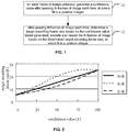
- FIG.2 is a schematic diagram illustrating a mapping relationship between confidence value (T) and target encoding frame rate (F), in accordance with an example of the present disclosure.
- T confidence value
- F target encoding frame rate
- FIG.2 suppose the original image frame rate is 25 frames per second, and a user expects to encode and record with such frame rate, when a focused-on target exists. And then, 25 may be taken as F max . Meanwhile, suppose a minimum frame rate acceptable to a user is 5 frames per second, 5 may be taken as F min .
- the mapping relationship curve may be moved towards lower left. That is, decrease the target encoding frame rate corresponding to the confidence value between T min and T max .
- FIG.2 may denote a change trend.
- various standard encoding modes may be employed, such as H.264/advanced video coding (AVC), Moving Picture Experts Group 4 (MPEG4), High Efficiency Video Coding (HEVC).
- AVC H.264/advanced video coding
- MPEG4 Moving Picture Experts Group 4
- HEVC High Efficiency Video Coding
- private compression algorithms may also be employed.
- the bit stream obtained after encoding may be stored into the storage space.
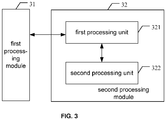
- FIG.3 is a schematic diagram illustrating structure of a device for storing a video image, in accordance with an example of the present disclosure.
- the device may include a first processing module 31 and a second processing module 32.
- the first processing module 31 For each frame of image collected, the first processing module 31 is to generate a confidence value after passing M frames of image each time, and transmit the confidence value to the second processing module 32.
- M is a positive integer.
- the second processing module 32 may determine a target encoding frame rate based on the confidence value latest generated, encode and record the N frames of image based on the target encoding frame rate determined.
- N is a positive integer.
- the second processing module 32 may include a first processing unit 321 and a second processing unit 322.
- the first processing unit 321 may respectively execute the following processes. Determine the target encoding frame rate corresponding to the confidence value latest generated, based on the mapping relationship curve between confidence value and target encoding frame rate. Transmit the determined target encoding frame rate to the second processing unit 322.
- the second processing unit 322 may encode and record the N frames of image, based on the target encoding frame rate determined.
- mapping relationship curve is a monotonic non-declined curve.
- the confidence value is a rational number located in [T min , T max ].
- a greater confidence value denotes a greater probability for a focused-on target exists in an image.
- the target encoding frame rate is a rational number located in [F min , F max ]. F min >0.
- the corresponding target encoding frame rate is F min .
- the corresponding target encoding frame rate is F max .
- the second processing unit 322 is further to determine actual bit stream R and expected bit stream S, every time a predetermined condition is met, and transmit R and S to the first processing unit 321.
- the first processing unit 321 is further to determine whether it is necessary to adjust the mapping relationship curve, based on R and S.
- adjust the mapping relationship curve may include as follows.
- S>R increase the target encoding frame rate corresponding to the confidence value between T min and T max .
- S ⁇ R decrease the target encoding frame rate corresponding to the confidence value between T min and T max .
- R consumed storage capacity/stored time.
- S un-consumed storage capacity/expected storage time.
- the target encoding frame rate may be continuously adjusted based on the confidence value. Encoding and recording may be executed based on the adjusted target encoding frame rate, so as to avoid the influence brought by misjudgment and missing judgment in the prior art to the largest extent, and improve adaptive capability and availability of system.
- a self-adaptive adjustment may be employed by the mapping between confidence value and target encoding frame rate, so as to enable storable recording time in storage space to be controllable.
- a relatively lower frame rate may be used to encode and record.
- the effects of fast forward may be achieved by playback, so as to improve efficiency when querying for playback video.
- the computer software product may be stored in a storage medium, which includes several instructions to enable a computer device (may be a personal computer (PC), server, or a network device, etc.), to execute the method of each foregoing example.
- a computer device may be a personal computer (PC), server, or a network device, etc.
- modules in the device of the foregoing examples may be distributed in the device of the examples, based on descriptions about the examples, or may be changed correspondingly to be located in one or more device, which is different from that in the foregoing examples.
- the modules in the foregoing example may be integrated into one module, or may be further divided into multiple sub-modules.
- a machine readable storage medium is also put forward, which may store instructions enabling a machine to execute the mapping management method mentioned in the present disclosure.
- a system or device equipped with such storage medium may be provided, and such storage medium may store software program codes, which may implement functions of any abovementioned example.
- a computer central processing unit (CPU) or microprocessor unit (MPU) of the system or device may be enabled to read and execute the program codes stored in the storage medium.
- the program codes read from the storage medium may implement functions of any abovementioned example.
- the program codes and storage medium storing the program codes may constitute a part of the foregoing technical solution for storing video images.
- the storage medium examples for providing program codes may include floppy disk, hard disk, magneto-optical disk (MOD), compact disk (CD)(such as CD-read-only memory (CD-ROM), CD-recordable (CD-R), CD-Rewriteable (CD-RW), digital video disc-ROM (DVD-ROM), DVD-random access memory (DVD-RAM), DVD-RW, DVD+RW), magnetic tape, non-volatile memory card and ROM.
- CD compact disk
- CD-ROM compact disk
- CD-ROM compact disk
- CD-R compact disk
- CD-R compact disk
- CD-RW compact disk
- DVD-ROM digital video disc-ROM
- DVD-RAM DVD-random access memory
- DVD-RW DVD+RW
- magnetic tape non-volatile memory card and ROM.
- the program codes may also be downloaded from a server computer through a communication network.
- the operating system (OS) of a computer may be enabled to execute part of or all of the actual operations, by executing the program codes read by the computer, or based on instructions in the program codes, thereby implementing functions of any of abovementioned example.
- the program codes read from the storage medium may be written into a memory set within an expansion board inserted into a computer, or be written into a memory set within an extension unit connected with a computer. Subsequently, based on the instructions of the program codes, the CPU installed on the expansion board or extension unit may be enabled to execute part of or all of actual operations, so as to implement functions of any of abovementioned example.
- another structure of a device for storing a video image in an example of the present disclosure may include a memory, and a processor in communication with the memory.
- the memory may store computer executable instructions, which may be executed by the processor.
- the computer executable instructions may include a first processing module instruction and a second processing module instruction, which may respectively indicate to execute functions of the first processing module and the second processing module as shown in FIG.3 .
Landscapes
- Engineering & Computer Science (AREA)
- Multimedia (AREA)
- Signal Processing (AREA)
- Physics & Mathematics (AREA)
- General Physics & Mathematics (AREA)
- Theoretical Computer Science (AREA)
- Compression Or Coding Systems Of Tv Signals (AREA)
- Television Signal Processing For Recording (AREA)
Description
- The present disclosure relates to video processing technologies, and more particularly, to a method and device for storing video images.
- Accompanying with people's increasing attention to safety, more and more places have installed monitoring equipment (such as camera), meanwhile monitoring system gradually develops towards high definition (HD). Correspondingly, storage space occupied by monitoring video is greater, and costs on hard disk are higher.
- However, in practical applications, what is captured by a monitoring device in most of the time throughout the day is invalid data, without occurrence of a focused-on target. Thus, there is an urgent problem to be solved about how to effectively reduce such invalid data, so as to save storage space and costs.
- Regarding the foregoing problem, the following processing modes are generally adopted in the prior art. The motion detecting or intelligent analysis technologies may be employed, to analyze whether a focused-on target exists in a video, and output a determination result about "yes" or "no". When the determination result is "yes", encode and record the video; otherwise, encoding and recording are not executed.
- However, some problems may occur when applying the foregoing modes in practical applications, for example, no matter employing the motion detecting or intelligent analysis technologies, as long as "yes" or "no" is used in the judgment, the probability of misjudgment and missing judgment may exist under technical conditions. When the misjudgment occurs, additional storage space may be consumed. When the missing judgment occurs, key data may be lost. Subsequently, adaptive capability and availability of system may be lowered.
-
US 2007/0189728A1 discloses a method of recording and reproducing surveillance images in a Digital Video Recorder (DVR). In one embodiment of the present invention, a recording speed such as a frame rate for surveillance images are controlled according to extent of motion of subjects in the surveillance detected through prediction between neighboring frames, and information about the controlled frame rates and information about time at which the frame rate is used may be managed and recorded in an associated manner. -
US 2007/0217765 A1 discloses the following technical solution. In a video recorder/player that increases a frame rate for only a channel in which an event occurs in images captured by a plurality of cameras and which performs event analysis with higher accuracy within limited processing resources and limited storage capacity, the channel in which the event occurs is set as an event CH and normal channels are set as normal CH. When any event occurs, a processing is divided in accordance with a situation at that time into a frame rate changing processing of the event CH, a frame rate changing processing of the normal CH and the event CH and a changing processing that changes the frame rate of the event CH within a possible range. -
US 6591014B1 provides an apparatus for coding a moving picture while coding a part of frames of the moving picture into intra-frames (I-pictures), a part of frames sandwiched between contiguous intra-frames into forward predictive frames (P-pictures), and frames sandwiched between a forward predictive frame and another forward predictive frame or an intra-frame into a bidirectionally predictive frames (B-pictures), comprising: a determining means for determining the number of B-pictures between a P-picture and another P-picture or an I-picture based on an output frame rate and a substantial frame rate which is defined as the number of pictures capable of being processed per unit time by the apparatus provided that only I-pictures and P-pictures are coded; and a coding means for coding the B-pictures by treating the B-pictures as frames with no differential data. - In view of above, the present disclosure provides a method and device for storing video image, so as to improve adaptive capability and availability of a system.
- To achieve the foregoing objectives, the technical solutions of the present disclosure are implemented as follows.
- A method for storing a video image, including:
- generating a confidence value after receiving M frames of an image each time, wherein M is a positive integer, the confidence value is a rational number greater than or equal to 0, a greater confidence value denotes a greater probability for a focused-on target exists in the image;
- after receiving N frames of the image each time, determining a target encoding frame rate based on the confidence value latest generated and a mapping relationship curve between confidence value and target encoding frame rate, encoding and recording the N frames of the image based on the target encoding frame rate determined, wherein N is a positive integer.
- A device for storing a video image, including a first processing module and a second processing module, wherein
the first processing module is to generate a confidence value after receiving M frames of an image each time, and transmitting the confidence value to the second processing module, wherein M is a positive integer, the confidence value is a rational number greater than or equal to 0, a greater confidence value denotes a greater probability for a focused-on target exists in the image; and
after receiving N frames of the image each time, the second processing module is to determine a target encoding frame rate based on the confidence value latest generated and a mapping relationship curve between confidence value and target encoding frame rate, encoding and recording the N frames of the image based on the determined target encoding frame rate, wherein N is a positive integer. - Thus, it can be seen that by adopting the technical solutions of the present disclosure, the target encoding frame rate may be continuously adjusted based on confidence value. And then, encoding and recording may be executed, based on the adjusted target encoding frame rate, so as to avoid influence brought by misjudgment and missing judgment in the prior art to the largest extent, and improve adaptive capability and availability of system.
-
-
FIG.1 is a flowchart illustrating a method for storing a video image, in accordance with an example of the present disclosure. -
FIG.2 is a schematic diagram illustrating a mapping relationship between confidence value and target encoding frame rate, in accordance with an example of the present disclosure. -
FIG.3 is a schematic diagram illustrating structure of a device for storing a video image, in accordance with an example of the present disclosure. - Regarding the problems in the prior art, the present disclosure provides a technical solution for storing a video image.
- To make the technical solutions of the present disclosure more clear, detailed descriptions about the technical solutions in the present disclosure are further provided in the following, accompanying with attached figures and examples.
-
FIG.1 is a flowchart illustrating a method for storing a video image, in accordance with an example of the present disclosure. As shown inFIG.1 , the method may include the following blocks 11-12. - In
block 11, for each frame of image collected, generate a confidence value after passing M frames of image each time, in which M is a positive integer. - The confidence value is a rational number located in [Tmin, Tmax]. Generally, Tmin is greater than or equal to 0. Greater confidence value denotes greater probability for a focused-on target exists in an image.
- For example, when the value of Tmin is 0, it denotes that a focused-on target does not exist in an image. When the value of Tmax is 100, it denotes that a focused-on target exists in an image. Different values in 0∼100 denote different possibilities for a focused-on target exists in an image.
- In practical applications, a confidence value may be generated for each frame of image, that is, a confidence value may be generated after passing every frame of image. Alternatively, a confidence value may also be generated after passing multiple frames of image each time. For example, when original image frame rate is 25 frames per second, a confidence value may be generated after passing 25 frames of image each time.
- The confidence value may be generated by adopting motion detecting or intelligent analysis technologies.
- The motion detecting technologies are generally applied to a fixed scene, and may obtain relevant information, such as area moved in a picture, moving range, and so on, by analyzing two adjacent frames of image, or analyzing multiple frames of image.
- The intelligent analysis technologies may analyze suspicious event behavior in a picture, and so on, by performing a background modeling, a target segmentation, a trajectory tracking to a scene image.
- In
block 12, after passing N frames of image each time, determine a target encoding frame rate based on a confidence value latest generated, encode and record the N frames of image based on the target encoding frame rate determined, in which N is a positive integer. - Specific implementation modes of
block 12 may be different, based on different values of N, which will be respectively described in the following. In addition, values of N and M may be the same, or may be different. - When N=1, for each frame of image, respectively determine whether it is necessary to encode the frame of image. When determining that it is necessary to encode the frame of image, encode and record the frame of image.
- Specifically speaking, the following processes may be respectively performed to each frame of image.
- 1) Determine the target encoding frame rate corresponding to the confidence value latest generated, based on a mapping relationship curve between confidence value and target encoding frame rate.
The mapping relationship curve is a monotonic non-declined curve.
The target encoding frame rate is a rational number located in [Fmin, Fmax], in which Fmin> 0.
When the confidence value is Tmin, the corresponding target encoding frame rate is Fmin. When the confidence value is Tmax, the corresponding target encoding frame rate is Fmax. - 2) Map the determined target encoding frame rate to an extraction factor X, in which X is a positive integer.
For example, the original image frame rate is 25 frames per second, the target encoding frame rate is 7 frames per second, and then an encoding frame ratio is 7/25, which is between 1/3 and 1/4. Subsequently, 7 frames of image may be relatively evenly extracted from the 25 frames of image, so as to be encoded and recorded. Correspondingly, 3 and 4 may be taken as the extraction factor. - 3) Determine frame number K of image un-encoded between the latest encoding and the frame of image, and determine whether K+1>=X. When determining that K+1>=X, encode and record the frame of image; otherwise, encoding and recording are not performed to the frame of image.
- That is, for the frame of image, when K+1>=X, encode and record the frame of image, and reset K. When K+1<X, encoding and recording are not performed to the frame of image, and add 1 to the value of K, that is, K++.
- When N>1, the following processes may be respectively performed to every N frames of image.
- 1) Determine the target encoding frame rate corresponding to the confidence value latest generated, based on the mapping relationship curve between confidence value and target encoding frame rate.
- 2) Encode and record the N frames of image, based on the determined target encoding frame rate.
- For example, the original image frame rate is 25 frames per second, N=25, the target encoding frame rate is 12.5 frames per second, and then, encode and record each frame of image extracted, based on a mode for extracting a frame every other frame.
- When N=1, the foregoing processing mode may be referred to as a first processing mode. When N>1, the processing mode may be referred to as a second processing mode. Essentially, when determining whether K+1>=X for each frame of image by using the second processing mode, the first processing mode may be achieved.
- In addition, the technical solutions of the present disclosure also put forward the following. Determine actual bit stream R and expected bit stream S, every time a predetermined condition is met. Determine whether it is necessary to adjust the mapping relationship curve based on R and S. When determining that it is necessary to adjust the mapping relationship curve based on R and S, adjust the mapping relationship curve.
- The abovementioned adjusting may include as follows. When S>R, increase the target encoding frame rate corresponding to the confidence value between Tmin and Tmax. When S<R, decrease the target encoding frame rate corresponding to the confidence value between Tmin and Tmax.
- In practical applications, a value obtained after dividing consumed storage capacity by storage time may be calculated, and a calculation result may be taken as R. For example, the consumed storage capacity in storage space is xGB, in which videos of y days are stored, and then the value of x/y may be taken as R. R may reflect actual consumption rate of storage statistically.
- A result obtained after dividing un-consumed storage capacity by expected storage time may also be calculated, and the calculation result may be taken as S. For example, the remaining (e.g., not-consumed) storage capacity in storage space is aGB, expected storage time is b days, and then, the value of a/b may be taken as S. S may reflect consumption rate of storage expecting to be achieved. The expected storage time may be set manually, and specific value of the expected storage time may be determined based on actual requirements.
- The unit of foregoing storage time is day, which may be also hour, second, and so on. In addition, other modes occurred to persons having ordinary skill in the art may also be used to determined R and S, which are not limited to the foregoing modes.
- Every time a predetermined condition is met, e.g., after scheduled time, or extra 10% of storage capacity is consumed each time, values of R and S may be determined once again. Alternatively, expect for the first time, R may be determined subsequently, and S may be calculated by using R. Correspondingly, every time after determining R and S, whether it is necessary to adjust the mapping relationship curve may be further determined. When determining that it is necessary to adjust the mapping relationship curve, adjust the mapping relationship curve; otherwise, not adjust the mapping relationship curve.
-
FIG.2 is a schematic diagram illustrating a mapping relationship between confidence value (T) and target encoding frame rate (F), in accordance with an example of the present disclosure. As shown inFIG.2 , suppose the original image frame rate is 25 frames per second, and a user expects to encode and record with such frame rate, when a focused-on target exists. And then, 25 may be taken as Fmax. Meanwhile, suppose a minimum frame rate acceptable to a user is 5 frames per second, 5 may be taken as Fmin. When S=R, the mapping relationship curve may be maintained without change. When S>R, it denotes that consumption of storage space is lower than expectation. To store more data, the mapping relationship curve may be moved towards upper right. That is, increase the target encoding frame rate corresponding to the confidence value between Tmin and Tmax. On the contrary, when S<R, it denotes that consumption of storage space is greater than the expectation. To achieve the expected storage time, the mapping relationship curve may be moved towards lower left. That is, decrease the target encoding frame rate corresponding to the confidence value between Tmin and Tmax. - In different conditions, such as S=R, S>R, S<R, specific values of the target encoding frame rate respectively corresponding to different confidence values may be determined based on actual requirements.
FIG.2 may denote a change trend. - In addition, in the technical solutions of the present disclosure, when encoding an image, various standard encoding modes may be employed, such as H.264/advanced video coding (AVC), Moving Picture Experts Group 4 (MPEG4), High Efficiency Video Coding (HEVC). Alternatively, private compression algorithms may also be employed. The bit stream obtained after encoding may be stored into the storage space.
- Based on the foregoing descriptions,
FIG.3 is a schematic diagram illustrating structure of a device for storing a video image, in accordance with an example of the present disclosure. As shown inFIG.3 , the device may include afirst processing module 31 and asecond processing module 32. - For each frame of image collected, the
first processing module 31 is to generate a confidence value after passing M frames of image each time, and transmit the confidence value to thesecond processing module 32. M is a positive integer. - After passing N frames of image each time, the
second processing module 32 may determine a target encoding frame rate based on the confidence value latest generated, encode and record the N frames of image based on the target encoding frame rate determined. N is a positive integer. - Specifically, the
second processing module 32 may include afirst processing unit 321 and asecond processing unit 322. - When N=1, the
first processing unit 321 is to execute the following processes for each frame of image. Determine the target encoding frame rate corresponding to the confidence value latest generated, based on the mapping relationship curve between confidence value and target encoding frame rate. Map the determined target encoding frame rate to an extraction factor X, in which X is a positive integer. Determine frame number K of image un-encoded between latest encoding and the frame of image, and determine whether K+1>=X. When determining that K+1>=X, thefirst processing unit 321 may inform thesecond processing unit 322 to execute functions of thesecond processing unit 322. Thesecond processing unit 322 is to encode and record the frame of image. - Alternatively, when N>1, for every N frames of image, the
first processing unit 321 may respectively execute the following processes. Determine the target encoding frame rate corresponding to the confidence value latest generated, based on the mapping relationship curve between confidence value and target encoding frame rate. Transmit the determined target encoding frame rate to thesecond processing unit 322. Thesecond processing unit 322 may encode and record the N frames of image, based on the target encoding frame rate determined. - Specifically, the mapping relationship curve is a monotonic non-declined curve.
- The confidence value is a rational number located in [Tmin, Tmax]. A greater confidence value denotes a greater probability for a focused-on target exists in an image.
- The target encoding frame rate is a rational number located in [Fmin, Fmax]. Fmin>0.
- When the confidence value is Tmin, the corresponding target encoding frame rate is Fmin. When the confidence value is Tmax, the corresponding target encoding frame rate is Fmax.
- In addition, the
second processing unit 322 is further to determine actual bit stream R and expected bit stream S, every time a predetermined condition is met, and transmit R and S to thefirst processing unit 321. - Correspondingly, the
first processing unit 321 is further to determine whether it is necessary to adjust the mapping relationship curve, based on R and S. When determining it is necessary to adjust the mapping relationship curve based on R and S, adjust the mapping relationship curve. The adjusting may include as follows. When S>R, increase the target encoding frame rate corresponding to the confidence value between Tmin and Tmax. When S<R, decrease the target encoding frame rate corresponding to the confidence value between Tmin and Tmax. - R=consumed storage capacity/stored time. S=un-consumed storage capacity/expected storage time.
- The specific work process of the device illustrated in
FIG.3 may refer to corresponding descriptions in the foregoing method examples, which are not repeated here. - In a word, by adopting the technical solutions of the present disclosure, the target encoding frame rate may be continuously adjusted based on the confidence value. Encoding and recording may be executed based on the adjusted target encoding frame rate, so as to avoid the influence brought by misjudgment and missing judgment in the prior art to the largest extent, and improve adaptive capability and availability of system. A self-adaptive adjustment may be employed by the mapping between confidence value and target encoding frame rate, so as to enable storable recording time in storage space to be controllable. In addition, by adopting the technical solutions of the present disclosure, for a scene where no focused-on target exists, a relatively lower frame rate may be used to encode and record. Thus, the effects of fast forward may be achieved by playback, so as to improve efficiency when querying for playback video.
- Based on the descriptions of foregoing examples, persons having ordinary skill in the art may clearly learn that, the foregoing examples may be implemented with a necessary general-purpose hardware platform having the aid of software, or may be implemented with hardware. In many cases, the previous one is a better implementation mode. Based on such understanding, the technical solutions of the present disclosure may be demonstrated with a software product. The computer software product may be stored in a storage medium, which includes several instructions to enable a computer device (may be a personal computer (PC), server, or a network device, etc.), to execute the method of each foregoing example.
- Persons having ordinary skill in the art may understand that the modules in the device of the foregoing examples may be distributed in the device of the examples, based on descriptions about the examples, or may be changed correspondingly to be located in one or more device, which is different from that in the foregoing examples. The modules in the foregoing example may be integrated into one module, or may be further divided into multiple sub-modules.
- Based on the technical solutions provided by each abovementioned example, a machine readable storage medium is also put forward, which may store instructions enabling a machine to execute the mapping management method mentioned in the present disclosure. Specifically, a system or device equipped with such storage medium may be provided, and such storage medium may store software program codes, which may implement functions of any abovementioned example. A computer (central processing unit (CPU) or microprocessor unit (MPU)) of the system or device may be enabled to read and execute the program codes stored in the storage medium.
- In such case, the program codes read from the storage medium may implement functions of any abovementioned example. Thus, the program codes and storage medium storing the program codes may constitute a part of the foregoing technical solution for storing video images.
- The storage medium examples for providing program codes may include floppy disk, hard disk, magneto-optical disk (MOD), compact disk (CD)(such as CD-read-only memory (CD-ROM), CD-recordable (CD-R), CD-Rewriteable (CD-RW), digital video disc-ROM (DVD-ROM), DVD-random access memory (DVD-RAM), DVD-RW, DVD+RW), magnetic tape, non-volatile memory card and ROM. Alternatively, the program codes may also be downloaded from a server computer through a communication network.
- In addition, it should be clear that, the operating system (OS) of a computer may be enabled to execute part of or all of the actual operations, by executing the program codes read by the computer, or based on instructions in the program codes, thereby implementing functions of any of abovementioned example.
- In addition, it should be understood that, the program codes read from the storage medium may be written into a memory set within an expansion board inserted into a computer, or be written into a memory set within an extension unit connected with a computer. Subsequently, based on the instructions of the program codes, the CPU installed on the expansion board or extension unit may be enabled to execute part of or all of actual operations, so as to implement functions of any of abovementioned example.
- For example, another structure of a device for storing a video image in an example of the present disclosure may include a memory, and a processor in communication with the memory. The memory may store computer executable instructions, which may be executed by the processor. The computer executable instructions may include a first processing module instruction and a second processing module instruction, which may respectively indicate to execute functions of the first processing module and the second processing module as shown in
FIG.3 .
Claims (12)
- A method for storing a video image, characterized by comprising:generating (11) a confidence value after receiving M frames of an image each time, wherein M is a positive integer, the confidence value is a rational number greater than or equal to 0, a greater confidence value denotes a greater probability for a focused-on target exists in the image;after receiving N frames of the image each time, determining (12) a target encoding frame rate based on the confidence value latest generated, and a mapping relationship curve between confidence value and target encoding frame rate, encoding and recording the N frames of the image based on the target encoding frame rate determined, wherein N is a positive integer.
- The method according to claim 1, wherein when N=1, after receiving N frames of the image each time, determining the target encoding frame rate based on the confidence value latest generated, and the mapping relationship curve between confidence value and target encoding frame rate, encoding and recording the N frames of the image based on the target encoding frame rate determined, comprise:
respectively executing the following processes for each frame of the image:determining the target encoding frame rate corresponding to the confidence value latest generated, based on the mapping relationship curve between confidence value and target encoding frame rate;mapping the determined target encoding frame rate to a positive integer X, determining frame number K of the image un-encoded between the latest encoding and the frame of image, anddetermining whether K+1>=X;when determining that K+1>=X, encoding and recording the frame of image. - The method according to claim 1, wherein when N>1, after receiving N frames of the image each time, determining the target encoding frame rate based on the confidence value latest generated, and the mapping relationship curve between confidence value and target encoding frame rate, encoding and recording the N frames of the image based on the target encoding frame rate determined, comprise:
respectively executing the following processes for every N frames of image:determining the target encoding frame rate corresponding to the confidence value latest generated, based on the mapping relationship curve between confidence value and target encoding frame rate; andencoding and recording the N frames of image based on the target encoding frame rate determined. - The method according to claim 2 or 3, wherein the mapping relationship curve is a monotonic non-declined curve, the confidence value is a rational number located in [Tmin, Tmax], Tmin>=0,;
wherein the target encoding frame rate is a rational number located in [Fmin, Fmax], Fmin>0;
when the confidence value is Tmin, the corresponding target encoding frame rate is Fmin;
when the confidence value is Tmax, the corresponding target encoding frame rate is Fmax. - The method according to claim 4, further comprising:determining an actual bit stream R and an expected bit stream S, every time when a predetermined condition is met,determining whether it is necessary to adjust the mapping relationship curve based on the actual bit stream R and the expected bit stream S;when determining that it is necessary to adjust the mapping relationship curve based on the actual bit stream R and the expected bit stream S, adjusting the mapping relationship curve;wherein the adjusting comprises:when the expected bit stream S is greater than the actual bit stream R, increasing the target encoding frame rate corresponding to the confidence value between Tmin and Tmax;when the expected bit stream S is less than the actual bit stream R, decreasing the target encoding frame rate corresponding to the confidence value between Tmin and Tmax.
- The method according to claim 5, wherein determining the actual bit stream R and the expected bit stream S comprises:calculating a first result obtained after dividing consumed storage capacity by stored time, and taking the first result as the actual bit stream R; andcalculating a second result obtained after dividing un-consumed storage capacity by expected storage time, and taking the second result as the expected bit stream S.
- A device for storing a video image, characterized by comprising a first processing module (31) and a second processing module (32), wherein
the first processing module (31) is to generate a confidence value after receiving M frames of an image each time, and transmitting the confidence value to the second processing module, wherein M is a positive integer, the confidence value is a rational number greater than or equal to 0, a greater confidence value denotes a greater probability for a focused-on target exists in the image; and
after receiving N frames of the image each time, the second processing module (32) is to determine a target encoding frame rate based on the confidence value latest generated and a mapping relationship curve between confidence value and target encoding frame rate, encoding and recording the N frames of the image based on the determined target encoding frame rate, wherein N is a positive integer. - The device according to claim 7, wherein the second processing module (32) comprises a first processing unit (321) and a second processing unit (322),
when N=1, the first processing unit (321) is to perform the following processes to each frame of the image:
determine the target encoding frame rate corresponding to the confidence value latest generated, based on the mapping relationship curve between confidence value and target encoding frame rate;
map the target encoding frame rate determined to a positive integer X;
determine frame number K of un-encoded image between the latest encoding and the frame of the image, and
determine whether K+1>=X;
when determining that K+1>=X, inform the second processing unit to execute functions of the second processing unit; and
the second processing unit (322) is to encode and record the frame of the image. - The device according to claim 7, wherein the second processing module (32) comprises a first processing unit (321) and a second processing unit (322),
when N>1, the first processing unit (321) is to perform the following processes to every N frames of the image:
determine the target encoding frame rate corresponding to the confidence value latest generated, based on the mapping relationship curve between confidence value and target encoding frame rate, and transmit the target encoding frame rate determined to the second processing unit; and
the second processing unit (322) is to encode and record the N frames of the image, based on the target encoding frame rate determined. - The device according to claim 8 or 9, wherein the mapping relationship curve is a monotonic non-declined curve, the confidence value is a rational number between [Tmin,Tmax], Tmin>=0, the target encoding frame rate is a rational number between [Fmin,Fmax], Fmin>0;
when the confidence value is Tmin, the corresponding target encoding frame rate is Fmin;
when the confidence value is Tmax, the corresponding target encoding frame rate is Fmax. - The device according to claim 10, wherein the second processing unit (322) is further to determine an actual bit stream R and an expected bit stream S, every time when a predetermined condition is met, and transmit R and S to the first processing unit; and
the first processing unit (321) is further to determine whether it is necessary to adjust the mapping relationship curve, based on R and S; when determining that it is necessary to adjust the mapping relationship curve based on R and S, the first processing unit is further to adjust the mapping relationship curve;
wherein the adjusting comprises:increasing the target encoding frame rate corresponding to the confidence value between Tmin and Tmin, when S>R; anddecreasing the target encoding frame rate corresponding to the confidence value between Tmin and Tmin, when S<R. - The device according to claim 11, wherein R=consumed storage capacity/stored time, and S=un-consumed storage capacity/expected storage time.
Applications Claiming Priority (2)
| Application Number | Priority Date | Filing Date | Title |
|---|---|---|---|
| CN201310447051.4A CN104519357B (en) | 2013-09-26 | 2013-09-26 | A kind of video image storage method and apparatus |
| PCT/CN2014/085495 WO2015043356A1 (en) | 2013-09-26 | 2014-08-29 | Video image storage method and apparatus |
Publications (3)
| Publication Number | Publication Date |
|---|---|
| EP2950529A1 EP2950529A1 (en) | 2015-12-02 |
| EP2950529A4 EP2950529A4 (en) | 2016-08-31 |
| EP2950529B1 true EP2950529B1 (en) | 2020-05-27 |
Family
ID=52742013
Family Applications (1)
| Application Number | Title | Priority Date | Filing Date |
|---|---|---|---|
| EP14848931.3A Active EP2950529B1 (en) | 2013-09-26 | 2014-08-29 | Video image storage method and apparatus |
Country Status (4)
| Country | Link |
|---|---|
| US (1) | US9578277B2 (en) |
| EP (1) | EP2950529B1 (en) |
| CN (1) | CN104519357B (en) |
| WO (1) | WO2015043356A1 (en) |
Families Citing this family (5)
| Publication number | Priority date | Publication date | Assignee | Title |
|---|---|---|---|---|
| US10638135B1 (en) * | 2018-01-29 | 2020-04-28 | Amazon Technologies, Inc. | Confidence-based encoding |
| CN110650320B (en) * | 2019-10-23 | 2021-11-02 | 海能达通信股份有限公司 | Dynamic frame rate storage method and device and monitoring equipment |
| CN112218025A (en) * | 2020-09-02 | 2021-01-12 | 北京迈格威科技有限公司 | Data processing method, device, server and storage medium |
| CN112261472A (en) * | 2020-10-19 | 2021-01-22 | 上海博泰悦臻电子设备制造有限公司 | Short video generation method and related equipment |
| CN112954456B (en) * | 2021-03-29 | 2023-06-20 | 深圳康佳电子科技有限公司 | Video data processing method, terminal and computer readable storage medium |
Family Cites Families (12)
| Publication number | Priority date | Publication date | Assignee | Title |
|---|---|---|---|---|
| JP3185763B2 (en) * | 1998-07-13 | 2001-07-11 | 日本電気株式会社 | Video encoding device |
| JP4387072B2 (en) | 2001-07-12 | 2009-12-16 | 三菱電機株式会社 | Portable video recording device |
| CN1750647A (en) * | 2005-06-02 | 2006-03-22 | 圆刚科技股份有限公司 | Monitoring system and monitoring method with automatic adjustment function |
| US8031777B2 (en) * | 2005-11-18 | 2011-10-04 | Apple Inc. | Multipass video encoding and rate control using subsampling of frames |
| KR101198157B1 (en) * | 2005-12-22 | 2012-11-12 | 엘지전자 주식회사 | Method for changing record frame rate in digital video recorder and reproducing method therof |
| JP4847165B2 (en) * | 2006-03-09 | 2011-12-28 | 株式会社日立製作所 | Video recording / reproducing method and video recording / reproducing apparatus |
| EP2140687A2 (en) * | 2007-04-03 | 2010-01-06 | Gary Demos | Flowfield motion compensation for video compression |
| JP4958758B2 (en) * | 2007-12-14 | 2012-06-20 | 三星電子株式会社 | Recording apparatus, reproducing apparatus, recording method, reproducing method, and program |
| CN101998111A (en) * | 2009-08-28 | 2011-03-30 | 杨占坤 | Video acquisition mode automatic conversion system and method of high-definition (HD) camera |
| CN102572357B (en) * | 2011-12-31 | 2018-03-30 | 中兴通讯股份有限公司 | The storage method and video monitoring system of a kind of video monitoring front-end |
| CN102724490B (en) * | 2012-06-01 | 2014-11-19 | 浙江宇视科技有限公司 | Method and device for stream control |
| CN102780869B (en) | 2012-06-27 | 2015-07-08 | 宇龙计算机通信科技(深圳)有限公司 | Video recording device and method |
-
2013
- 2013-09-26 CN CN201310447051.4A patent/CN104519357B/en active Active
-
2014
- 2014-08-29 WO PCT/CN2014/085495 patent/WO2015043356A1/en not_active Ceased
- 2014-08-29 EP EP14848931.3A patent/EP2950529B1/en active Active
- 2014-08-29 US US14/763,176 patent/US9578277B2/en active Active
Also Published As
| Publication number | Publication date |
|---|---|
| CN104519357A (en) | 2015-04-15 |
| US9578277B2 (en) | 2017-02-21 |
| EP2950529A1 (en) | 2015-12-02 |
| EP2950529A4 (en) | 2016-08-31 |
| CN104519357B (en) | 2018-10-30 |
| WO2015043356A1 (en) | 2015-04-02 |
| US20150365623A1 (en) | 2015-12-17 |
Similar Documents
| Publication | Publication Date | Title |
|---|---|---|
| US12062268B2 (en) | Methods and apparatus for using video analytics to detect regions for privacy protection within images from moving cameras | |
| JP6016332B2 (en) | Image processing apparatus and image processing method | |
| WO2022177591A1 (en) | Surveillance video streams with embedded object data | |
| JP2009033423A (en) | Image compression method and image processing apparatus | |
| US9578277B2 (en) | Method and device for storing video images | |
| CN103685914A (en) | Image management apparatus and management method | |
| CN110198475B (en) | Video processing method, apparatus, device, server and readable storage medium | |
| US8363726B2 (en) | Electronic apparatus, motion vector detecting method, and program therefor | |
| US20140328383A1 (en) | Encoding apparatus and method | |
| KR102263071B1 (en) | Method for video monitoring, Apparatus for video monitoring and Computer program for the same | |
| US9560365B2 (en) | Image coding device, image decoding device, image coding method, and image decoding method | |
| JP6582876B2 (en) | Video storage system, video storage device, and program | |
| JP2006020330A (en) | Process and apparatus for compressing video documents | |
| EP3506227B1 (en) | Systems and methods for intelligently recording video data streams | |
| KR100906075B1 (en) | Intelligent security system using H.264 | |
| CN102833620B (en) | System and method for time optimized encoding | |
| KR102369798B1 (en) | Data management method and data management system | |
| KR102557904B1 (en) | The Method of Detecting Section in which a Movement Frame Exists | |
| JP4835540B2 (en) | Electronic device, video feature detection method and program | |
| CN112905821B (en) | Image display method, device, equipment and storage medium | |
| CN119814744A (en) | A desktop protocol area streaming method, desktop protocol server, desktop protocol system, storage medium and computer program product | |
| CN117640929A (en) | Image processing method, device and related equipment | |
| JP2008085539A (en) | Program, detection method, detection device, image processing method, and image processing device | |
| JP2018019194A (en) | Moving image formation method and moving image formation device | |
| JP2009044330A (en) | Electronic device, video data determination method and program |
Legal Events
| Date | Code | Title | Description |
|---|---|---|---|
| PUAI | Public reference made under article 153(3) epc to a published international application that has entered the european phase |
Free format text: ORIGINAL CODE: 0009012 |
|
| 17P | Request for examination filed |
Effective date: 20150812 |
|
| AK | Designated contracting states |
Kind code of ref document: A1 Designated state(s): AL AT BE BG CH CY CZ DE DK EE ES FI FR GB GR HR HU IE IS IT LI LT LU LV MC MK MT NL NO PL PT RO RS SE SI SK SM TR |
|
| AX | Request for extension of the european patent |
Extension state: BA ME |
|
| A4 | Supplementary search report drawn up and despatched |
Effective date: 20160801 |
|
| RIC1 | Information provided on ipc code assigned before grant |
Ipc: H04N 19/146 20140101ALI20160726BHEP Ipc: H04N 19/196 20140101ALI20160726BHEP Ipc: H04N 9/804 20060101ALI20160726BHEP Ipc: H04N 5/91 20060101ALI20160726BHEP Ipc: H04N 19/172 20140101ALI20160726BHEP Ipc: H04N 7/18 20060101AFI20160726BHEP |
|
| DAX | Request for extension of the european patent (deleted) | ||
| RAP1 | Party data changed (applicant data changed or rights of an application transferred) |
Owner name: HANGZHOU HIKVISION DIGITAL TECHNOLOGY CO., LTD. |
|
| STAA | Information on the status of an ep patent application or granted ep patent |
Free format text: STATUS: EXAMINATION IS IN PROGRESS |
|
| 17Q | First examination report despatched |
Effective date: 20190816 |
|
| REG | Reference to a national code |
Ref country code: DE Ref legal event code: R079 Ref document number: 602014066032 Country of ref document: DE Free format text: PREVIOUS MAIN CLASS: H04N0007180000 Ipc: G06K0009000000 |
|
| GRAP | Despatch of communication of intention to grant a patent |
Free format text: ORIGINAL CODE: EPIDOSNIGR1 |
|
| STAA | Information on the status of an ep patent application or granted ep patent |
Free format text: STATUS: GRANT OF PATENT IS INTENDED |
|
| RIC1 | Information provided on ipc code assigned before grant |
Ipc: H04N 19/136 20140101ALI20191112BHEP Ipc: G06K 9/00 20060101AFI20191112BHEP Ipc: H04N 9/804 20060101ALI20191112BHEP Ipc: H04N 19/177 20140101ALI20191112BHEP Ipc: H04N 19/132 20140101ALI20191112BHEP |
|
| INTG | Intention to grant announced |
Effective date: 20191218 |
|
| GRAS | Grant fee paid |
Free format text: ORIGINAL CODE: EPIDOSNIGR3 |
|
| GRAA | (expected) grant |
Free format text: ORIGINAL CODE: 0009210 |
|
| STAA | Information on the status of an ep patent application or granted ep patent |
Free format text: STATUS: THE PATENT HAS BEEN GRANTED |
|
| AK | Designated contracting states |
Kind code of ref document: B1 Designated state(s): AL AT BE BG CH CY CZ DE DK EE ES FI FR GB GR HR HU IE IS IT LI LT LU LV MC MK MT NL NO PL PT RO RS SE SI SK SM TR |
|
| REG | Reference to a national code |
Ref country code: GB Ref legal event code: FG4D |
|
| REG | Reference to a national code |
Ref country code: CH Ref legal event code: EP |
|
| REG | Reference to a national code |
Ref country code: DE Ref legal event code: R096 Ref document number: 602014066032 Country of ref document: DE |
|
| REG | Reference to a national code |
Ref country code: AT Ref legal event code: REF Ref document number: 1275299 Country of ref document: AT Kind code of ref document: T Effective date: 20200615 |
|
| REG | Reference to a national code |
Ref country code: NL Ref legal event code: FP |
|
| REG | Reference to a national code |
Ref country code: LT Ref legal event code: MG4D |
|
| PG25 | Lapsed in a contracting state [announced via postgrant information from national office to epo] |
Ref country code: SE Free format text: LAPSE BECAUSE OF FAILURE TO SUBMIT A TRANSLATION OF THE DESCRIPTION OR TO PAY THE FEE WITHIN THE PRESCRIBED TIME-LIMIT Effective date: 20200527 Ref country code: FI Free format text: LAPSE BECAUSE OF FAILURE TO SUBMIT A TRANSLATION OF THE DESCRIPTION OR TO PAY THE FEE WITHIN THE PRESCRIBED TIME-LIMIT Effective date: 20200527 Ref country code: PT Free format text: LAPSE BECAUSE OF FAILURE TO SUBMIT A TRANSLATION OF THE DESCRIPTION OR TO PAY THE FEE WITHIN THE PRESCRIBED TIME-LIMIT Effective date: 20200928 Ref country code: NO Free format text: LAPSE BECAUSE OF FAILURE TO SUBMIT A TRANSLATION OF THE DESCRIPTION OR TO PAY THE FEE WITHIN THE PRESCRIBED TIME-LIMIT Effective date: 20200827 Ref country code: IS Free format text: LAPSE BECAUSE OF FAILURE TO SUBMIT A TRANSLATION OF THE DESCRIPTION OR TO PAY THE FEE WITHIN THE PRESCRIBED TIME-LIMIT Effective date: 20200927 Ref country code: GR Free format text: LAPSE BECAUSE OF FAILURE TO SUBMIT A TRANSLATION OF THE DESCRIPTION OR TO PAY THE FEE WITHIN THE PRESCRIBED TIME-LIMIT Effective date: 20200828 Ref country code: LT Free format text: LAPSE BECAUSE OF FAILURE TO SUBMIT A TRANSLATION OF THE DESCRIPTION OR TO PAY THE FEE WITHIN THE PRESCRIBED TIME-LIMIT Effective date: 20200527 |
|
| PG25 | Lapsed in a contracting state [announced via postgrant information from national office to epo] |
Ref country code: LV Free format text: LAPSE BECAUSE OF FAILURE TO SUBMIT A TRANSLATION OF THE DESCRIPTION OR TO PAY THE FEE WITHIN THE PRESCRIBED TIME-LIMIT Effective date: 20200527 Ref country code: RS Free format text: LAPSE BECAUSE OF FAILURE TO SUBMIT A TRANSLATION OF THE DESCRIPTION OR TO PAY THE FEE WITHIN THE PRESCRIBED TIME-LIMIT Effective date: 20200527 Ref country code: BG Free format text: LAPSE BECAUSE OF FAILURE TO SUBMIT A TRANSLATION OF THE DESCRIPTION OR TO PAY THE FEE WITHIN THE PRESCRIBED TIME-LIMIT Effective date: 20200827 Ref country code: HR Free format text: LAPSE BECAUSE OF FAILURE TO SUBMIT A TRANSLATION OF THE DESCRIPTION OR TO PAY THE FEE WITHIN THE PRESCRIBED TIME-LIMIT Effective date: 20200527 |
|
| REG | Reference to a national code |
Ref country code: AT Ref legal event code: MK05 Ref document number: 1275299 Country of ref document: AT Kind code of ref document: T Effective date: 20200527 |
|
| PG25 | Lapsed in a contracting state [announced via postgrant information from national office to epo] |
Ref country code: AL Free format text: LAPSE BECAUSE OF FAILURE TO SUBMIT A TRANSLATION OF THE DESCRIPTION OR TO PAY THE FEE WITHIN THE PRESCRIBED TIME-LIMIT Effective date: 20200527 |
|
| PG25 | Lapsed in a contracting state [announced via postgrant information from national office to epo] |
Ref country code: CZ Free format text: LAPSE BECAUSE OF FAILURE TO SUBMIT A TRANSLATION OF THE DESCRIPTION OR TO PAY THE FEE WITHIN THE PRESCRIBED TIME-LIMIT Effective date: 20200527 Ref country code: RO Free format text: LAPSE BECAUSE OF FAILURE TO SUBMIT A TRANSLATION OF THE DESCRIPTION OR TO PAY THE FEE WITHIN THE PRESCRIBED TIME-LIMIT Effective date: 20200527 Ref country code: EE Free format text: LAPSE BECAUSE OF FAILURE TO SUBMIT A TRANSLATION OF THE DESCRIPTION OR TO PAY THE FEE WITHIN THE PRESCRIBED TIME-LIMIT Effective date: 20200527 Ref country code: SM Free format text: LAPSE BECAUSE OF FAILURE TO SUBMIT A TRANSLATION OF THE DESCRIPTION OR TO PAY THE FEE WITHIN THE PRESCRIBED TIME-LIMIT Effective date: 20200527 Ref country code: IT Free format text: LAPSE BECAUSE OF FAILURE TO SUBMIT A TRANSLATION OF THE DESCRIPTION OR TO PAY THE FEE WITHIN THE PRESCRIBED TIME-LIMIT Effective date: 20200527 Ref country code: AT Free format text: LAPSE BECAUSE OF FAILURE TO SUBMIT A TRANSLATION OF THE DESCRIPTION OR TO PAY THE FEE WITHIN THE PRESCRIBED TIME-LIMIT Effective date: 20200527 Ref country code: DK Free format text: LAPSE BECAUSE OF FAILURE TO SUBMIT A TRANSLATION OF THE DESCRIPTION OR TO PAY THE FEE WITHIN THE PRESCRIBED TIME-LIMIT Effective date: 20200527 Ref country code: ES Free format text: LAPSE BECAUSE OF FAILURE TO SUBMIT A TRANSLATION OF THE DESCRIPTION OR TO PAY THE FEE WITHIN THE PRESCRIBED TIME-LIMIT Effective date: 20200527 |
|
| PG25 | Lapsed in a contracting state [announced via postgrant information from national office to epo] |
Ref country code: SK Free format text: LAPSE BECAUSE OF FAILURE TO SUBMIT A TRANSLATION OF THE DESCRIPTION OR TO PAY THE FEE WITHIN THE PRESCRIBED TIME-LIMIT Effective date: 20200527 Ref country code: PL Free format text: LAPSE BECAUSE OF FAILURE TO SUBMIT A TRANSLATION OF THE DESCRIPTION OR TO PAY THE FEE WITHIN THE PRESCRIBED TIME-LIMIT Effective date: 20200527 |
|
| REG | Reference to a national code |
Ref country code: DE Ref legal event code: R097 Ref document number: 602014066032 Country of ref document: DE |
|
| PG25 | Lapsed in a contracting state [announced via postgrant information from national office to epo] |
Ref country code: MC Free format text: LAPSE BECAUSE OF FAILURE TO SUBMIT A TRANSLATION OF THE DESCRIPTION OR TO PAY THE FEE WITHIN THE PRESCRIBED TIME-LIMIT Effective date: 20200527 |
|
| REG | Reference to a national code |
Ref country code: CH Ref legal event code: PL |
|
| PLBE | No opposition filed within time limit |
Free format text: ORIGINAL CODE: 0009261 |
|
| STAA | Information on the status of an ep patent application or granted ep patent |
Free format text: STATUS: NO OPPOSITION FILED WITHIN TIME LIMIT |
|
| PG25 | Lapsed in a contracting state [announced via postgrant information from national office to epo] |
Ref country code: LU Free format text: LAPSE BECAUSE OF NON-PAYMENT OF DUE FEES Effective date: 20200829 Ref country code: LI Free format text: LAPSE BECAUSE OF NON-PAYMENT OF DUE FEES Effective date: 20200831 Ref country code: CH Free format text: LAPSE BECAUSE OF NON-PAYMENT OF DUE FEES Effective date: 20200831 |
|
| 26N | No opposition filed |
Effective date: 20210302 |
|
| REG | Reference to a national code |
Ref country code: BE Ref legal event code: MM Effective date: 20200831 |
|
| PG25 | Lapsed in a contracting state [announced via postgrant information from national office to epo] |
Ref country code: SI Free format text: LAPSE BECAUSE OF FAILURE TO SUBMIT A TRANSLATION OF THE DESCRIPTION OR TO PAY THE FEE WITHIN THE PRESCRIBED TIME-LIMIT Effective date: 20200527 |
|
| PG25 | Lapsed in a contracting state [announced via postgrant information from national office to epo] |
Ref country code: BE Free format text: LAPSE BECAUSE OF NON-PAYMENT OF DUE FEES Effective date: 20200831 Ref country code: IE Free format text: LAPSE BECAUSE OF NON-PAYMENT OF DUE FEES Effective date: 20200829 |
|
| REG | Reference to a national code |
Ref country code: DE Ref legal event code: R079 Ref document number: 602014066032 Country of ref document: DE Free format text: PREVIOUS MAIN CLASS: G06K0009000000 Ipc: G06V0010000000 |
|
| PG25 | Lapsed in a contracting state [announced via postgrant information from national office to epo] |
Ref country code: TR Free format text: LAPSE BECAUSE OF FAILURE TO SUBMIT A TRANSLATION OF THE DESCRIPTION OR TO PAY THE FEE WITHIN THE PRESCRIBED TIME-LIMIT Effective date: 20200527 Ref country code: MT Free format text: LAPSE BECAUSE OF FAILURE TO SUBMIT A TRANSLATION OF THE DESCRIPTION OR TO PAY THE FEE WITHIN THE PRESCRIBED TIME-LIMIT Effective date: 20200527 Ref country code: CY Free format text: LAPSE BECAUSE OF FAILURE TO SUBMIT A TRANSLATION OF THE DESCRIPTION OR TO PAY THE FEE WITHIN THE PRESCRIBED TIME-LIMIT Effective date: 20200527 |
|
| PG25 | Lapsed in a contracting state [announced via postgrant information from national office to epo] |
Ref country code: MK Free format text: LAPSE BECAUSE OF FAILURE TO SUBMIT A TRANSLATION OF THE DESCRIPTION OR TO PAY THE FEE WITHIN THE PRESCRIBED TIME-LIMIT Effective date: 20200527 |
|
| P01 | Opt-out of the competence of the unified patent court (upc) registered |
Effective date: 20230424 |
|
| PGFP | Annual fee paid to national office [announced via postgrant information from national office to epo] |
Ref country code: NL Payment date: 20250724 Year of fee payment: 12 |
|
| PGFP | Annual fee paid to national office [announced via postgrant information from national office to epo] |
Ref country code: DE Payment date: 20250812 Year of fee payment: 12 |
|
| PGFP | Annual fee paid to national office [announced via postgrant information from national office to epo] |
Ref country code: GB Payment date: 20250826 Year of fee payment: 12 |
|
| PGFP | Annual fee paid to national office [announced via postgrant information from national office to epo] |
Ref country code: FR Payment date: 20250828 Year of fee payment: 12 |