EP2950523A1 - Method of estimating flicker on recorded video by camcorder - Google Patents
Method of estimating flicker on recorded video by camcorder Download PDFInfo
- Publication number
- EP2950523A1 EP2950523A1 EP14305795.8A EP14305795A EP2950523A1 EP 2950523 A1 EP2950523 A1 EP 2950523A1 EP 14305795 A EP14305795 A EP 14305795A EP 2950523 A1 EP2950523 A1 EP 2950523A1
- Authority
- EP
- European Patent Office
- Prior art keywords
- flicker
- video
- camcorded
- estimating
- camcorded video
- Prior art date
- Legal status (The legal status is an assumption and is not a legal conclusion. Google has not performed a legal analysis and makes no representation as to the accuracy of the status listed.)
- Withdrawn
Links
Images


Classifications
-
- H—ELECTRICITY
- H04—ELECTRIC COMMUNICATION TECHNIQUE
- H04N—PICTORIAL COMMUNICATION, e.g. TELEVISION
- H04N5/00—Details of television systems
- H04N5/76—Television signal recording
-
- G—PHYSICS
- G06—COMPUTING OR CALCULATING; COUNTING
- G06T—IMAGE DATA PROCESSING OR GENERATION, IN GENERAL
- G06T7/00—Image analysis
- G06T7/0002—Inspection of images, e.g. flaw detection
-
- H—ELECTRICITY
- H04—ELECTRIC COMMUNICATION TECHNIQUE
- H04N—PICTORIAL COMMUNICATION, e.g. TELEVISION
- H04N23/00—Cameras or camera modules comprising electronic image sensors; Control thereof
- H04N23/70—Circuitry for compensating brightness variation in the scene
- H04N23/745—Detection of flicker frequency or suppression of flicker wherein the flicker is caused by illumination, e.g. due to fluorescent tube illumination or pulsed LED illumination
-
- H—ELECTRICITY
- H04—ELECTRIC COMMUNICATION TECHNIQUE
- H04N—PICTORIAL COMMUNICATION, e.g. TELEVISION
- H04N5/00—Details of television systems
- H04N5/76—Television signal recording
- H04N5/91—Television signal processing therefor
- H04N5/913—Television signal processing therefor for scrambling ; for copy protection
-
- G—PHYSICS
- G06—COMPUTING OR CALCULATING; COUNTING
- G06T—IMAGE DATA PROCESSING OR GENERATION, IN GENERAL
- G06T2207/00—Indexing scheme for image analysis or image enhancement
- G06T2207/30—Subject of image; Context of image processing
- G06T2207/30168—Image quality inspection
-
- H—ELECTRICITY
- H04—ELECTRIC COMMUNICATION TECHNIQUE
- H04N—PICTORIAL COMMUNICATION, e.g. TELEVISION
- H04N5/00—Details of television systems
- H04N5/76—Television signal recording
- H04N5/91—Television signal processing therefor
- H04N5/913—Television signal processing therefor for scrambling ; for copy protection
- H04N2005/91307—Television signal processing therefor for scrambling ; for copy protection by adding a copy protection signal to the video signal
- H04N2005/91335—Television signal processing therefor for scrambling ; for copy protection by adding a copy protection signal to the video signal the copy protection signal being a watermark
-
- H—ELECTRICITY
- H04—ELECTRIC COMMUNICATION TECHNIQUE
- H04N—PICTORIAL COMMUNICATION, e.g. TELEVISION
- H04N21/00—Selective content distribution, e.g. interactive television or video on demand [VOD]
- H04N21/80—Generation or processing of content or additional data by content creator independently of the distribution process; Content per se
- H04N21/83—Generation or processing of protective or descriptive data associated with content; Content structuring
- H04N21/835—Generation of protective data, e.g. certificates
- H04N21/8358—Generation of protective data, e.g. certificates involving watermark
Definitions
- the present disclosure relates to a method of estimating a flicker on a recorded video by a camcorder.
- Decoding a digital watermark on a camcorded video is a difficult task in general.
- Camcording causes various artifacts, such as geometric distortions, temporal transform and frame merging, luminance and chrominance distortions.
- Numerous methods have been proposed to counter geometric or temporal distortions.
- the flicker effect has never been addressed in a watermark detection scope.
- a simple solution is to apply a de-flickering filter to the video, for instance, by using a VirtualDub filter.
- the de-flickering filter will not only suppress the flicker, but also alter other components of the video, and will thus impair the watermark signal as well. It is thus very important to be able to selectively remove the flicker without damaging other components of the video.
- FIG. 1 is an image of an example of flicker on a recorded camcorded video by a camcorder or video camera.
- the luminosity of images varies in a periodic way, and sometimes varies also across the image itself (for example, if the camcorder uses a rolling shutter, i.e. each line is acquired with a small delay) .
- the display backlight signal which is a periodic signal at a "high" frequency (for example, around 180Hz)
- a lower frequency typically between 50 and 60 Hz.
- the flicker parameters for example, frequency, phase, amplitude and so on
- estimating the flicker can be used to enhance the image quality by selectively removing or controlling the flicker besides the application of watermark detection.
- embodiments of the present invention may provide a novel and useful method of estimating a flicker on a camcorded video solving one or more of the problems discussed above.
- a method of estimating a flicker on a camcorded video In the method, a camcorded video with unknown camcording and display setting is firstly obtained. The camcorded video includes a flicker. Next, a spectrum of the camcorded video is obtained by using a temporal discrete Fourier transform. Then, a temporal frequency of the flicker is estimated by looking for a local maximum value in the spectrum of the camcorded video.
- a camcorded video is obtained.
- the camcorded video may have unknown camcording (recording) and display settings because the camcorded video may include a pirated edition.
- the camcording and display settings of such a pirated edition video are not known.
- the method of estimating the flicker on the camcorded video of the embodiment can be applied to such a camcorded video of the pirated edition.
- such a camcorded video includes a flicker.
- a camcorded video with unknown camcording settings is obtained firstly, and then flicker parameters are blindly estimated on the video.
- the flicker parameters mean various items to identify the flicker.
- these estimated parameters are used to suppress or attenuate the flicker, prior to watermark detection.
- a first step of an embodiment of the present invention is to accurately model the flicker.
- This model will be used as a basis for the flicker parameters estimation. From the physical understanding of the phenomenon, as well as carefully designed experiments, the following generic model is provided as equation (1).
- Y x y t X x y t + ⁇ ⁇ X x y t + ⁇ ⁇ cos f t ⁇ t + f y ⁇ y + ⁇
- the flicker component is the second term on the right side of equation (1) as follows: ⁇ ⁇ X x y t + ⁇ ⁇ cos f t ⁇ t + f y ⁇ y + ⁇
- f y and f t are respectively the vertical and temporal flicker frequencies, and ⁇ is the flicker phase.
- the vertical flicker component is due to the fact that each line is captured with a small delay compared to the previous one, thus the flicker signal is slightly "shifted" from one line to the other, and this phase shift is equal to f y y.
- the values of f t , f y , and ⁇ are parameters of the flicker.
- the values of ⁇ and ⁇ are also parameters of the flicker.
- the backlight is modulated in amplitude by a pixel array, depending on the pixel luminance value.
- the liquid crystal element corresponding to this pixel will attenuate more or less the amplitude of the backlight (for example, maximum attenuation corresponding to black, and minimal attenuation corresponding to white).
- the flicker amplitude A varies linearly with the local video brightness X (which is larger for bright areas than for dark areas) as equation (3) as follows.
- A ⁇ ⁇ X + ⁇
- ⁇ and ⁇ are ⁇ « 1, and ⁇ « X MAX . That is to say, the flicker amplitude is small compared to the video luminance.
- Experimental measures show that ⁇ varies, for example, between 0.02 for normal flicker, and 0.2 for heavy flicker. For example, ⁇ is typically lower than 5 in the absolute value.
- the original video X is not available beside the camcorded video Y.
- the challenge will be to estimate the entire flicker parameters f t , f y , ⁇ , ⁇ , ⁇ and in particular the amplitude parameters ⁇ and ⁇ in a blind way.
- the flicker parameters f t , f y , ⁇ , ⁇ , ⁇ are estimated by using the Temporal Discrete Fourier Transform (which may be hereinafter called a "TDFT") of the camcorded luminance.
- TDFT Temporal Discrete Fourier Transform
- the temporal flicker frequency f t is estimated by finding a local maximal value in the TDFT.
- FIG. 2 is an example of a camcorded video spectrum. In FIG. 2 , there is a local maximum value around 5 Hz, and there is a local maximum value around 10 Hz, which is smaller than that of 5 Hz.
- the major novelty of the embodiment of the present invention consists in a method of estimating the flicker amplitude parameters, ⁇ and ⁇ in addition to estimating the parameters of f t , f y and ⁇ .
- the flicker Since the flicker is caused by the display backlight, and the backlight amplitude is modulated at each pixel by the pixel luminance value, the flicker amplitude thus varies linearly with the pixel brightness.
- the embodiment of the present invention proposes the following steps.
- FIG. 3 is a flowchart illustrating a method of estimating a flicker by using flicker parameters.
- a camcorded video is provided for a camcorder that implements the method of estimating the flicker by using the parameters.
- step S1 the vector of line averages is obtained by calculation for each frame Y t of the camcorded video by using the following equation (4).
- step S2 the Temporal Discrete Fourier transform (Temporal DFT) of Y' is performed for each line y to obtain a spectrum of each line noted as Y' y (f).
- Temporal DFT Temporal Discrete Fourier transform
- a first approximation of the temporal flicker frequency f t is retrieved and obtained by taking the local maximum of
- a first embodiment is to select a line number y (for instance, y being at the middle of the image), and to find a local maximum on
- Another possibility is to find the frequency yielding maximal value for each line y, then to combine all the estimation together (for instance by averaging all the maximal frequencies, or performing a majority vote).
- step S4 the approximation found in step S3 is refined by computing a Temporal Discrete Fourier Transform on the zero-padded signal Y' (y, t) and take the maximum around the previous approximated estimation of the temporal flicker frequency f t .
- step S5 the vertical flicker frequency f y and the phase ⁇ are estimated.
- FIG. 4 is a graph illustrating a flicker phase for all lines of an image.
- FIG. 5 is a graph illustrating an unwrapped flicker phase, derived from FIG. 4 .
- step S5 of FIG. 3 the "unwrapped" phase ⁇ y of Y' y (f t ) is computed for all y (i.e. all line numbers), using ⁇ y which is the phase of Y' y (f t ).
- ⁇ y can be computed using the following formula (5), (6) and (7).
- ⁇ y ⁇ y - ⁇ y - 1 + ⁇ ⁇ mod 2 ⁇ ⁇ - ⁇
- step S6 the amplitude parameters ⁇ any ⁇ are estimated.
- a mean square error method can be used, which is detailed in various documents.
- the TDFT coefficients Y'(.) are computed for a given line y of the video (for instance y being the middle line of the image).
- the parameters ⁇ and ⁇ can be obtained by using equations (9) and (10).
- the flicker can be properly estimated.
- a preferred embodiment is to compute the de-flickered image from camcorded image Y(x,y,t) by using the following equation (11) and the estimated flicker parameters.
- Z x y t Y x y t - ⁇ ⁇ cos f t ⁇ t + f y ⁇ y + ⁇ 1 + ⁇ ⁇ cos f t ⁇ t + f y ⁇ y + ⁇ Z(x, y, t) is always defined since ⁇ « 1.
- the method was successfully tested on videos camcorded with various exposure values, thus therein various flicker amplitudes.
- the method made it possible to estimate the flicker parameters and to attenuate the flicker.
- flicker compensation After flicker compensation, synchronization and watermark detection was improved.
- the watermark was detectable on videos where the detection otherwise failed. On other videos, flicker compensation enables the watermark detection score to increase.
- the method enables the flicker on camcorded video to be attenuated, which improves watermark detection. This makes it possible to retrieve the watermark even on highly impaired camcorded videos. Moreover, the method can provide a high-quality image by removing the flicker from the image.
Landscapes
- Engineering & Computer Science (AREA)
- Multimedia (AREA)
- Signal Processing (AREA)
- Quality & Reliability (AREA)
- Computer Vision & Pattern Recognition (AREA)
- Physics & Mathematics (AREA)
- General Physics & Mathematics (AREA)
- Theoretical Computer Science (AREA)
- Picture Signal Circuits (AREA)
Abstract
A method of estimating a flicker on a camcorded video firstly obtains a camcorded video with unknown camcording and display settings. The camcorded video includes a flicker and a watermark. Next, a spectrum of the camcorded video is obtained by using a temporal discrete Fourier transform. Then, a temporal frequency of the flicker is estimated by looking for a local maximum value in the spectrum of the camcorded video.
Description
- The present disclosure relates to a method of estimating a flicker on a recorded video by a camcorder.
- Decoding a digital watermark on a camcorded video is a difficult task in general. Camcording causes various artifacts, such as geometric distortions, temporal transform and frame merging, luminance and chrominance distortions. Numerous methods have been proposed to counter geometric or temporal distortions. However, the flicker effect has never been addressed in a watermark detection scope. A simple solution is to apply a de-flickering filter to the video, for instance, by using a VirtualDub filter. However, such a solution is not satisfactory since it has been designed to produce a visually satisfying result, and not to accurately preserve the signal components. Actually, the de-flickering filter will not only suppress the flicker, but also alter other components of the video, and will thus impair the watermark signal as well. It is thus very important to be able to selectively remove the flicker without damaging other components of the video.
- Camcording a video produces numerous artifacts on the captured images. Among the artifacts, flicker is commonly observed especially when camcording a LCD display.
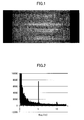
FIG. 1 is an image of an example of flicker on a recorded camcorded video by a camcorder or video camera. As shown inFIG. 1 , the luminosity of images varies in a periodic way, and sometimes varies also across the image itself (for example, if the camcorder uses a rolling shutter, i.e. each line is acquired with a small delay) . This is due to aliasing, because the display backlight signal, which is a periodic signal at a "high" frequency (for example, around 180Hz), is sampled by the camcorder at a lower frequency (typically between 50 and 60 Hz). If the camcorded video has been watermarked, such a luminance variation may render the watermark detection difficult, since the flicker amplitude is often larger than the watermark amplitude. Hence, suppressing the flicker will enhance the watermark detection. However, the flicker parameters (for example, frequency, phase, amplitude and so on) differ from one camcording setting to another and must therefore be estimated blindly from the camcorded video. Moreover, estimating the flicker can be used to enhance the image quality by selectively removing or controlling the flicker besides the application of watermark detection. - Accordingly, embodiments of the present invention may provide a novel and useful method of estimating a flicker on a camcorded video solving one or more of the problems discussed above.
- More specifically, according to an embodiment of the present invention, there is provided a method of estimating a flicker on a camcorded video. In the method, a camcorded video with unknown camcording and display setting is firstly obtained. The camcorded video includes a flicker. Next, a spectrum of the camcorded video is obtained by using a temporal discrete Fourier transform. Then, a temporal frequency of the flicker is estimated by looking for a local maximum value in the spectrum of the camcorded video.
- Other objects, features, and advantages of an embodiment of the present invention will become more apparent from the following detailed description when read in conjunction with the accompanying drawings.
-
-
FIG. 1 is an image of an example of flicker on a camcorded image; -
FIG. 2 is an example of a camcorded video temporal spectrum; -
FIG. 3 is a flowchart illustrating a method of estimating a flicker by using flicker parameters of an embodiment of the present invention; -
FIG. 4 is a graph illustrating a flicker phase for all lines of an image; and -
FIG. 5 is a graph illustrating an unwrapped flicker phase, derived fromFIG. 4 . - A description is given below of embodiments of the present invention, with reference to the drawings.
- According to an embodiment of a method of estimating a flicker on a camcorded (recorded) video, to begin with, a camcorded video is obtained. The camcorded video may have unknown camcording (recording) and display settings because the camcorded video may include a pirated edition. In many cases, the camcording and display settings of such a pirated edition video are not known. The method of estimating the flicker on the camcorded video of the embodiment can be applied to such a camcorded video of the pirated edition. In many cases, such a camcorded video includes a flicker. Hence, in the method, to remove the flicker, a camcorded video with unknown camcording settings is obtained firstly, and then flicker parameters are blindly estimated on the video. Here, the flicker parameters mean various items to identify the flicker. Next, these estimated parameters are used to suppress or attenuate the flicker, prior to watermark detection.
- A first step of an embodiment of the present invention is to accurately model the flicker. This model will be used as a basis for the flicker parameters estimation. From the physical understanding of the phenomenon, as well as carefully designed experiments, the following generic model is provided as equation (1).

- Where X(x,y,t) is the luminance value of pixel x,y of frame t of the original video, and Y(x,y,t) is the camcorded luminance value, the flicker component is the second term on the right side of equation (1) as follows:

- In formula (2), fy and ft are respectively the vertical and temporal flicker frequencies, and ϕ is the flicker phase. The vertical flicker component is due to the fact that each line is captured with a small delay compared to the previous one, thus the flicker signal is slightly "shifted" from one line to the other, and this phase shift is equal to fyy. The values of ft, fy, and ϕ are parameters of the flicker. The values of α and β are also parameters of the flicker.
- In a LCD display, the backlight is modulated in amplitude by a pixel array, depending on the pixel luminance value. The liquid crystal element corresponding to this pixel will attenuate more or less the amplitude of the backlight (for example, maximum attenuation corresponding to black, and minimal attenuation corresponding to white). Thus, the flicker amplitude A varies linearly with the local video brightness X (which is larger for bright areas than for dark areas) as equation (3) as follows.

- In practice, appropriate examples of values of α and β are α « 1, and β « XMAX. That is to say, the flicker amplitude is small compared to the video luminance. Experimental measures show that α varies, for example, between 0.02 for normal flicker, and 0.2 for heavy flicker. For example, β is typically lower than 5 in the absolute value.
- In a realistic case, and in particular for watermark detection, the original video X is not available beside the camcorded video Y. Thus, the challenge will be to estimate the entire flicker parameters ft, fy, ϕ, α, β and in particular the amplitude parameters α and β in a blind way. The flicker parameters ft, fy, ϕ, α, β are estimated by using the Temporal Discrete Fourier Transform (which may be hereinafter called a "TDFT") of the camcorded luminance. First, the temporal flicker frequency ft is estimated by finding a local maximal value in the TDFT.
FIG. 2 is an example of a camcorded video spectrum. InFIG. 2 , there is a local maximum value around 5 Hz, and there is a local maximum value around 10 Hz, which is smaller than that of 5 Hz. - Next, the phases of the TDFT for each line are compared to find the vertical flicker frequency fy and the phase ϕ. Finally, using both TDFT coefficients at the lowest frequency and TDFT coefficients around ft makes it possible to find the amplitude parameters α and β.
- Next, a description is given below of an embodiment of a process of accurately estimating the flicker parameters in a blind way, i.e. using only the pirated camcorded video, without the original video and any knowledge of the capture settings (e.g., type of camcorder, camcorder settings, display settings, etc.). The major novelty of the embodiment of the present invention consists in a method of estimating the flicker amplitude parameters, α and β in addition to estimating the parameters of ft, fy and φ.
- Since the flicker is caused by the display backlight, and the backlight amplitude is modulated at each pixel by the pixel luminance value, the flicker amplitude thus varies linearly with the pixel brightness.
- To estimate the flicker parameters of the generic flicker model described above, the embodiment of the present invention proposes the following steps.
-
FIG. 3 is a flowchart illustrating a method of estimating a flicker by using flicker parameters. - Before performing the flowchart in
FIG. 3 , a camcorded video is provided for a camcorder that implements the method of estimating the flicker by using the parameters. - In step S1, the vector of line averages is obtained by calculation for each frame Yt of the camcorded video by using the following equation (4).

- In step S2, the Temporal Discrete Fourier transform (Temporal DFT) of Y' is performed for each line y to obtain a spectrum of each line noted as Y'y(f).
- In step S3, a first approximation of the temporal flicker frequency ft is retrieved and obtained by taking the local maximum of |Y'(f)| with f not belonging to the signal lowest frequencies. A first embodiment is to select a line number y (for instance, y being at the middle of the image), and to find a local maximum on |Y'(f)|. For instance, find the maximum of | Yy' (f) | for f>0.1, where f is the normalized frequency such that the spectrum is defined for 0≤f<0.5. Another possibility is to find the frequency yielding maximal value for each line y, then to combine all the estimation together (for instance by averaging all the maximal frequencies, or performing a majority vote).
- In step S4, the approximation found in step S3 is refined by computing a Temporal Discrete Fourier Transform on the zero-padded signal Y' (y, t) and take the maximum around the previous approximated estimation of the temporal flicker frequency ft.
- In step S5, the vertical flicker frequency fy and the phase ϕ are estimated.
-
FIG. 4 is a graph illustrating a flicker phase for all lines of an image.FIG. 5 is a graph illustrating an unwrapped flicker phase, derived fromFIG. 4 . - In step S5 of
FIG. 3 , the "unwrapped" phase Ψy of Y'y (ft) is computed for all y (i.e. all line numbers), using Φy which is the phase of Y'y(ft). φy can be computed using the following formula (5), (6) and (7).


- In formula (2), considering the flicker as a temporal signal, it is noted that the flicker phase is (fyy + ϕ), which is a linear function of the line number y. Therefore, the unwrapped phase Ψy should obey the following equation.

Hence, by performing linear regression on the phase Ψy, an estimation of the vertical flicker frequency fy can be obtained, as well as an estimation of the offset phase ϕ. - In step S6, the amplitude parameters α any β are estimated. To achieve this aim, a mean square error method can be used, which is detailed in various documents. As a result, the following equations (9) and (10) can be obtained.


Where the TDFT coefficients Y'(.) are computed for a given line y of the video (for instance y being the middle line of the image). Ψ is the flicker phase for said line y and is given by : Ψ=fyy+ϕ. Θ is a parameter determining the frequency range on which the estimation is computed. In a particular embodiment, θ=10/M where M is the total number of frames of the video (M determines the frequency resolution of the TDFT). Re(x) gives the real part of complex number x, andY gives the complex conjugate of complex number Y. - Thus, the parameters α and β can be obtained by using equations (9) and (10). By obtaining the parameters α and β, the flicker can be properly estimated.
- Once all the flicker parameters have been estimated, the flicker signal shall be subtracted from the camcorded video prior to watermark detection. A preferred embodiment is to compute the de-flickered image from camcorded image Y(x,y,t) by using the following equation (11) and the estimated flicker parameters.
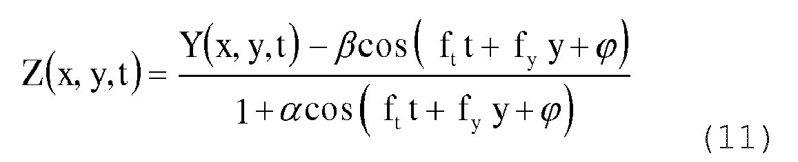
Z(x, y, t) is always defined since α « 1. - The method was successfully tested on videos camcorded with various exposure values, thus therein various flicker amplitudes. The method made it possible to estimate the flicker parameters and to attenuate the flicker. After flicker compensation, synchronization and watermark detection was improved. The watermark was detectable on videos where the detection otherwise failed. On other videos, flicker compensation enables the watermark detection score to increase.
- Thus, the method enables the flicker on camcorded video to be attenuated, which improves watermark detection. This makes it possible to retrieve the watermark even on highly impaired camcorded videos. Moreover, the method can provide a high-quality image by removing the flicker from the image.
- All examples and conditional language recited herein are intended for pedagogical purposes to aid the reader in understanding the invention and the concepts contributed by the inventor to furthering the art, and are to be construed as being without limitation to such specifically recited examples and conditions, nor does the organization of such examples in the specification relate to a showing of the superiority or inferiority of the invention. Although the embodiments of the present invention have been described in detail, it should be understood that various changes, substitutions, and alterations could be made hereto without departing from the spirit and scope of the invention.
Claims (10)
- A method of estimating a flicker on a camcorded video, the method comprising steps of:obtaining a camcorded video with unknown camcording and display settings, the camcorded video including a flicker;obtaining a spectrum of the camcorded video by using a temporal discrete Fourier transform; andestimating a temporal frequency of the flicker by looking for a local maximum value in the spectrum of the camcorded video.
- The method as claimed in claim 1, wherein the step of obtaining the spectrum of the camcorded video and the step of estimating the temporal frequency of the flicker are performed for a predetermined line of a frame of the camcorded video.
- The method as claimed in claim 1, wherein the step of obtaining the spectrum of the camcorded video and the step of estimating the temporal frequency of the flicker are performed for each line of a frame of the camcorded video.
- The method as claimed in claim 3, further comprising a step of:estimating a flicker vertical frequency and a phase by performing a linear regression on a phase of a temporal Fourier coefficient at the flicker temporal frequency for each line of the frame of the camcorded video.
- The method as claimed in claim 4, further comprising a step of:estimating amplitude parameters of the flicker by using the temporal Fourier coefficient around zero and around the temporal frequency of the camcorded video.
- The method as claimed in claim 5, further comprising a step of:estimating a flicker signal of the flicker for each pixel of the frame based on the estimated temporal frequency, the flicker vertical frequency, the phase and the amplitude parameters.
- The method as claimed in claim 6, further comprising a step of:removing the flicker from the camcorded video by subtracting the estimated flicker signal from each pixel of the frame.
- The method as claimed in claim 7, wherein the step of estimating the flicker signal and the step of removing the flicker from the camcorded video are performed for each frame.
- The method as claimed in claim 8, further comprising a step of:detecting a watermark from the camcorded video after the step of removing the flicker from the camcorded video.
- The method as claimed in claim 3, further comprising:computing a vector of a line average for each frame between the step of obtaining the camcorded video and the step of obtaining the spectrum of the camcorded video.
Priority Applications (1)
| Application Number | Priority Date | Filing Date | Title |
|---|---|---|---|
| EP14305795.8A EP2950523A1 (en) | 2014-05-28 | 2014-05-28 | Method of estimating flicker on recorded video by camcorder |
Applications Claiming Priority (1)
| Application Number | Priority Date | Filing Date | Title |
|---|---|---|---|
| EP14305795.8A EP2950523A1 (en) | 2014-05-28 | 2014-05-28 | Method of estimating flicker on recorded video by camcorder |
Publications (1)
| Publication Number | Publication Date |
|---|---|
| EP2950523A1 true EP2950523A1 (en) | 2015-12-02 |
Family
ID=50943254
Family Applications (1)
| Application Number | Title | Priority Date | Filing Date |
|---|---|---|---|
| EP14305795.8A Withdrawn EP2950523A1 (en) | 2014-05-28 | 2014-05-28 | Method of estimating flicker on recorded video by camcorder |
Country Status (1)
| Country | Link |
|---|---|
| EP (1) | EP2950523A1 (en) |
Cited By (1)
| Publication number | Priority date | Publication date | Assignee | Title |
|---|---|---|---|---|
| JP2023034920A (en) * | 2021-08-31 | 2023-03-13 | キヤノン株式会社 | Imaging apparatus, flicker detection method, and program |
Citations (4)
| Publication number | Priority date | Publication date | Assignee | Title |
|---|---|---|---|---|
| WO2000007363A1 (en) * | 1998-07-28 | 2000-02-10 | Intel Corporation | Method and apparatus for reducing flicker effects from discharge lamps during pipelined digital video capture |
| US20030030744A1 (en) * | 2001-08-10 | 2003-02-13 | Baer Richard L. | Method and apparatus for removing flicker from images |
| US6710818B1 (en) * | 1999-10-08 | 2004-03-23 | Matsushita Electric Industrial Co., Ltd. | Illumination flicker detection apparatus, an illumination flicker compensation apparatus, and an ac line frequency detection apparatus, methods of detecting illumination flicker, compensating illumination flicker, and measuring ac line frequency |
| WO2004066626A1 (en) * | 2003-01-20 | 2004-08-05 | Koninklijke Philips Electronics N.V. | Watermark embedding and detection of a motion image signal |
-
2014
- 2014-05-28 EP EP14305795.8A patent/EP2950523A1/en not_active Withdrawn
Patent Citations (4)
| Publication number | Priority date | Publication date | Assignee | Title |
|---|---|---|---|---|
| WO2000007363A1 (en) * | 1998-07-28 | 2000-02-10 | Intel Corporation | Method and apparatus for reducing flicker effects from discharge lamps during pipelined digital video capture |
| US6710818B1 (en) * | 1999-10-08 | 2004-03-23 | Matsushita Electric Industrial Co., Ltd. | Illumination flicker detection apparatus, an illumination flicker compensation apparatus, and an ac line frequency detection apparatus, methods of detecting illumination flicker, compensating illumination flicker, and measuring ac line frequency |
| US20030030744A1 (en) * | 2001-08-10 | 2003-02-13 | Baer Richard L. | Method and apparatus for removing flicker from images |
| WO2004066626A1 (en) * | 2003-01-20 | 2004-08-05 | Koninklijke Philips Electronics N.V. | Watermark embedding and detection of a motion image signal |
Cited By (1)
| Publication number | Priority date | Publication date | Assignee | Title |
|---|---|---|---|---|
| JP2023034920A (en) * | 2021-08-31 | 2023-03-13 | キヤノン株式会社 | Imaging apparatus, flicker detection method, and program |
Similar Documents
| Publication | Publication Date | Title |
|---|---|---|
| CN102550017B (en) | Defect detecting method for imaging device, and imaging device | |
| US7602440B2 (en) | Image processing apparatus and method, recording medium, and program | |
| US8311116B2 (en) | Method and apparatus for periodic structure handling for motion compensation | |
| US20030189655A1 (en) | Method of adaptive noise smoothing/restoration in spatio-temporal domain and high-definition image capturing device thereof | |
| US8606032B2 (en) | Image processing method, device and program to process a moving image | |
| CN101087366A (en) | Video-signal processing method and video-signal processing device | |
| EP2133837A1 (en) | Image processing apparatus and program storage medium | |
| US8036485B2 (en) | Systems and methods for measuring loss of detail in a video codec block | |
| Tanaka et al. | Motion blur parameter identification from a linearly blurred image | |
| US9749592B2 (en) | Processing of image data comprising effects of turbulence in a liquid medium | |
| KR101004064B1 (en) | Image Matching Device and Image Matching Method | |
| KR101336240B1 (en) | Method and apparatus for image processing using saved image | |
| US20120033137A1 (en) | Image processing device and method and image display device | |
| CN1860779B (en) | Image processing device and method | |
| Baudry et al. | Modeling the flicker effect in camcorded videos to improve watermark robustness | |
| WO2018094823A1 (en) | Uniformity test method and system for display screen | |
| Balamurugan et al. | Source camera identification using SPN with PRNU estimation and enhancement | |
| US20230209210A1 (en) | System and method for image banding detection | |
| KR100839922B1 (en) | Apparatus and method for removing color noise using adaptive mean filter | |
| JP5091880B2 (en) | Moving image noise removing apparatus and moving image noise removing program | |
| KR20070020996A (en) | Color error correction device and method | |
| Khan et al. | Quality measures for blind image deblurring | |
| JP7300164B2 (en) | noise reduction method | |
| Artmann | Extending the Utility of Noise Equivalent Quanta (NEQ) for Dynamic Range Measurement in Imaging Systems | |
| KR100617651B1 (en) | Plaid Noise Reduction Device and Method |
Legal Events
| Date | Code | Title | Description |
|---|---|---|---|
| AK | Designated contracting states |
Kind code of ref document: A1 Designated state(s): AL AT BE BG CH CY CZ DE DK EE ES FI FR GB GR HR HU IE IS IT LI LT LU LV MC MK MT NL NO PL PT RO RS SE SI SK SM TR |
|
| AX | Request for extension of the european patent |
Extension state: BA ME |
|
| PUAI | Public reference made under article 153(3) epc to a published international application that has entered the european phase |
Free format text: ORIGINAL CODE: 0009012 |
|
| STAA | Information on the status of an ep patent application or granted ep patent |
Free format text: STATUS: THE APPLICATION IS DEEMED TO BE WITHDRAWN |
|
| 18D | Application deemed to be withdrawn |
Effective date: 20160603 |