EP2950442A2 - Main field voltage limiter in brushless synchronous machines - Google Patents
Main field voltage limiter in brushless synchronous machines Download PDFInfo
- Publication number
- EP2950442A2 EP2950442A2 EP15167976.8A EP15167976A EP2950442A2 EP 2950442 A2 EP2950442 A2 EP 2950442A2 EP 15167976 A EP15167976 A EP 15167976A EP 2950442 A2 EP2950442 A2 EP 2950442A2
- Authority
- EP
- European Patent Office
- Prior art keywords
- voltage
- main field
- limit
- machine
- field current
- Prior art date
- Legal status (The legal status is an assumption and is not a legal conclusion. Google has not performed a legal analysis and makes no representation as to the accuracy of the status listed.)
- Granted
Links
Images


Classifications
-
- H—ELECTRICITY
- H02—GENERATION; CONVERSION OR DISTRIBUTION OF ELECTRIC POWER
- H02P—CONTROL OR REGULATION OF ELECTRIC MOTORS, ELECTRIC GENERATORS OR DYNAMO-ELECTRIC CONVERTERS; CONTROLLING TRANSFORMERS, REACTORS OR CHOKE COILS
- H02P31/00—Arrangements for regulating or controlling electric motors not provided for in groups H02P1/00 - H02P5/00, H02P7/00 or H02P21/00 - H02P29/00
-
- H—ELECTRICITY
- H02—GENERATION; CONVERSION OR DISTRIBUTION OF ELECTRIC POWER
- H02K—DYNAMO-ELECTRIC MACHINES
- H02K19/00—Synchronous motors or generators
- H02K19/02—Synchronous motors
-
- H—ELECTRICITY
- H02—GENERATION; CONVERSION OR DISTRIBUTION OF ELECTRIC POWER
- H02P—CONTROL OR REGULATION OF ELECTRIC MOTORS, ELECTRIC GENERATORS OR DYNAMO-ELECTRIC CONVERTERS; CONTROLLING TRANSFORMERS, REACTORS OR CHOKE COILS
- H02P25/00—Arrangements or methods for the control of AC motors characterised by the kind of AC motor or by structural details
- H02P25/02—Arrangements or methods for the control of AC motors characterised by the kind of AC motor or by structural details characterised by the kind of motor
- H02P25/022—Synchronous motors
- H02P25/03—Synchronous motors with brushless excitation
-
- H—ELECTRICITY
- H02—GENERATION; CONVERSION OR DISTRIBUTION OF ELECTRIC POWER
- H02P—CONTROL OR REGULATION OF ELECTRIC MOTORS, ELECTRIC GENERATORS OR DYNAMO-ELECTRIC CONVERTERS; CONTROLLING TRANSFORMERS, REACTORS OR CHOKE COILS
- H02P9/00—Arrangements for controlling electric generators for the purpose of obtaining a desired output
- H02P9/14—Arrangements for controlling electric generators for the purpose of obtaining a desired output by variation of field
-
- H—ELECTRICITY
- H02—GENERATION; CONVERSION OR DISTRIBUTION OF ELECTRIC POWER
- H02P—CONTROL OR REGULATION OF ELECTRIC MOTORS, ELECTRIC GENERATORS OR DYNAMO-ELECTRIC CONVERTERS; CONTROLLING TRANSFORMERS, REACTORS OR CHOKE COILS
- H02P9/00—Arrangements for controlling electric generators for the purpose of obtaining a desired output
- H02P9/14—Arrangements for controlling electric generators for the purpose of obtaining a desired output by variation of field
- H02P9/26—Arrangements for controlling electric generators for the purpose of obtaining a desired output by variation of field using discharge tubes or semiconductor devices
- H02P9/30—Arrangements for controlling electric generators for the purpose of obtaining a desired output by variation of field using discharge tubes or semiconductor devices using semiconductor devices
- H02P9/302—Brushless excitation
-
- H—ELECTRICITY
- H02—GENERATION; CONVERSION OR DISTRIBUTION OF ELECTRIC POWER
- H02P—CONTROL OR REGULATION OF ELECTRIC MOTORS, ELECTRIC GENERATORS OR DYNAMO-ELECTRIC CONVERTERS; CONTROLLING TRANSFORMERS, REACTORS OR CHOKE COILS
- H02P2207/00—Indexing scheme relating to controlling arrangements characterised by the type of motor
- H02P2207/05—Synchronous machines, e.g. with permanent magnets or DC excitation
Definitions
- the subject matter disclosed herein relates to brushless synchronous machines.
- a regulator delivers the field excitation to the rotating field poles.
- An increase or decrease in the field current to the regulator affects the generator field voltage (main field voltage).
- the field current that affects the main field voltage is controlled by a feedback loop, but the resulting main field voltage may not be conveniently measurable due to rotation of the field.
- a fault in the feedback loop or the system (gird) may cause the field current and, consequently, the main field voltage to exceed rated values.
- a brushless synchronous machine with a limiter for main field voltage includes a regulator configured to use a field current to excite main field windings and generate the main field voltage; and a limiter configured to limit the field current to maintain the main field voltage corresponding to the field current below a limit based on a transfer function.
- a method of limiting main field voltage in a brushless synchronous machine includes regulating a field current to excite main field windings and generate the main field voltage; and limiting the field current to maintain the main field voltage corresponding to the field current below a limit based on a transfer function.
- the field current to a regulator affects the main field voltage of a synchronous machine (generator). While the field current is controlled through a feedback loop, a fault in the feedback or the system (grid) cannot be detected at the main field voltage, because the main field voltage is difficult to measure with conventionally available sensors.
- Embodiments of the systems and method described herein relate to developing a transfer function to estimate main field voltage based on field current. Additional embodiments relate to limiting the main field voltage by limiting the applied field current.
- FIG. 1 is a block diagram of an exemplary brushless synchronous machine according to embodiments of the invention.
- the exemplary brushless synchronous machine is a generator 100.
- the generator 100 includes a regulator 140 that supplies the main generator 105.
- a field current 110 is input to the regulator 140, which may include a winding and a rectifier.
- the main field voltage 120 is the voltage applied at the main field winding 125 that results in the terminal voltage 130 of the generator 100. Due to rotation of the windings 125, the main field voltage 120 is difficult to measure.
- This main field voltage 120 is related to the input field current 110 and has a limit, indicated by the manufacturer of the brushless synchronous machine, for proper operation.
- a transfer function 210 FIG.
- the specified maximum value may be based on a recommendation of the manufacturer of the brushless synchronous machine. Alternatively, the specified maximum value may be based on customer or region specific limits on the main field voltage, which may be lower than the manufacturer recommended maximum.
- FIG. 2 illustrates the transfer function 210 relating field current 110 to main field voltage 120 in a brushless synchronous machine according to embodiments of the invention.
- the field current 110 is shown on the x-axis and the resulting rectified output voltage 220 is shown on the y-axis. That is, the rectified output voltage 220 is the regulator 140 output voltage which is applied as the main field voltage 120.
- Three different curves are shown. The curve indicating the ideal relationship between field current 110 and main field voltage 120 does not account for saturation.
- the saturation refers to a limit on the magnetization of the ferromagnetic material (e.g., iron) forming the windings.
- the ferromagnetic material e.g., iron
- the curve indicating the relationship between field current 110 and rectified output voltage 220 without load indicates that the main generator 105 is not attached. That is, the load on the regulator 140 that has the input field current 110 (as shown in FIG. 1 ) is the main generator 105.
- the curve (transfer function 210) indicating the relationship between field current 110 and rectified output voltage 220 with a load (the main generator 105) indicates the relationship between the field current 110 and the main field voltage 120.
- the transfer function 210 is developed by applying a known curve-fitting technique to the various data points 230 provided by the manufacturer of the brushless synchronous machine.
- the data points 230 relate to saturation points, for example.
- FIG. 3 illustrates a limiter 310 according to an embodiment of the invention facilitated by the transfer function 210 developed according to embodiments of the invention.
- the automatic voltage regulator (AVR) set point 320 is determined according to a known feedback loop using the rated terminal voltage 130.
- the AVR set point 320 controls the field current 110 that is ultimately output according to a known process 330 shown in FIG. 3 .
- a fault occurs in the feedback or the system that determines the AVR set point 320, a high field current 110 can be requested as a result.
- the AVR set point 320 (and resulting requested field current 110 value) can continue to increase in successive control loops.
- the feedback will cause the AVR set point 320 to be increased to try to affect the desired terminal voltage 130.
- the field current 110 can ultimately increase, based on the control loop for the AVR set point 320, to a value at which the corresponding main field voltage 120 exceeds the specified limit.
- the specified limit may be based on a recommendation by the manufacturer of the brushless synchronous machine, by the customer, or in accordance with a limit in the region of operation. This can, in turn, negatively affect the operation of the brushless synchronous machine.
- the limiter 310 acts as a hard limit on the field current 110 resulting from the AVR set point 320. By using the transfer function 210 developed as discussed with reference to FIG. 2 , the field current 110 corresponding with the maximum recommended or desired main field voltage 120 is determined. This corresponding field current 110 is used to limit (in the limiter 310) the AVR set point 320.
- the AVR set point 320 keeps increasing, as in the case of the exemplary fault discussed above, that increase will ultimately be limited by the limiter 310, based on the transfer function 210, to ensure that the resulting field current 110 does not reach a level at which the main field voltage 120 exceeds the specified limit.
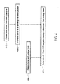
- FIG. 4 is a process flow of a method of limiting main field voltage 120 in a brushless synchronous machine according to embodiments of the invention.
- obtaining data points from the manufacturer of the brushless synchronous machine facilitates performing a curve fit, at block 420, to develop the transfer function 210 relating the field current 110 to main field voltage 120.
- the process includes obtaining a main field voltage 120 limit. This limit may be based on the manufacturer recommendation or a user (customer of the brushless synchronous machine) or a region or use of the brushless synchronous machine.
- the limiter 310 can limit the AVR set point 320 to ensure that the field current 110 does not exceed the value at which the resulting main field voltage 120 will exceed the limit.
Landscapes
- Engineering & Computer Science (AREA)
- Power Engineering (AREA)
- Control Of Eletrric Generators (AREA)
Abstract
Description
- The subject matter disclosed herein relates to brushless synchronous machines.
- In a brushless synchronous machine, such as a synchronous generator, a regulator delivers the field excitation to the rotating field poles. An increase or decrease in the field current to the regulator affects the generator field voltage (main field voltage). The field current that affects the main field voltage is controlled by a feedback loop, but the resulting main field voltage may not be conveniently measurable due to rotation of the field. As a result, a fault in the feedback loop or the system (gird) may cause the field current and, consequently, the main field voltage to exceed rated values.
- According to one aspect of the invention, a brushless synchronous machine with a limiter for main field voltage includes a regulator configured to use a field current to excite main field windings and generate the main field voltage; and a limiter configured to limit the field current to maintain the main field voltage corresponding to the field current below a limit based on a transfer function.
- According to another aspect of the invention, a method of limiting main field voltage in a brushless synchronous machine includes regulating a field current to excite main field windings and generate the main field voltage; and limiting the field current to maintain the main field voltage corresponding to the field current below a limit based on a transfer function.
- These and other advantages and features will become more apparent from the following description taken in conjunction with the drawings.
- The subject matter, which is regarded as the invention, is particularly pointed out and distinctly claimed in the claims at the conclusion of the specification. The foregoing and other features, and advantages of the invention are apparent from the following detailed description taken in conjunction with the accompanying drawings in which:
-
FIG. 1 is a block diagram of an exemplary brushless synchronous machine according to embodiments of the invention; -
FIG 2 illustrates the transfer function relating field current to main field voltage in a brushless synchronous machine according to embodiments of the invention; -
FIG 3 illustrates a limiter according to an embodiment of the invention facilitated by the transfer function developed according to embodiments of the invention; and -
FIG. 4 is a process flow of a method of limiting main field voltage in a brushless synchronous machine according to embodiments of the invention. - The detailed description explains embodiments of the invention, together with advantages and features, by way of example with reference to the drawings.
- As noted above, the field current to a regulator affects the main field voltage of a synchronous machine (generator). While the field current is controlled through a feedback loop, a fault in the feedback or the system (grid) cannot be detected at the main field voltage, because the main field voltage is difficult to measure with conventionally available sensors. Embodiments of the systems and method described herein relate to developing a transfer function to estimate main field voltage based on field current. Additional embodiments relate to limiting the main field voltage by limiting the applied field current.
-
FIG. 1 is a block diagram of an exemplary brushless synchronous machine according to embodiments of the invention. The exemplary brushless synchronous machine is agenerator 100. Thegenerator 100 includes aregulator 140 that supplies themain generator 105. Afield current 110 is input to theregulator 140, which may include a winding and a rectifier. Themain field voltage 120 is the voltage applied at the main field winding 125 that results in theterminal voltage 130 of thegenerator 100. Due to rotation of thewindings 125, themain field voltage 120 is difficult to measure. Thismain field voltage 120 is related to theinput field current 110 and has a limit, indicated by the manufacturer of the brushless synchronous machine, for proper operation. To ensure that themain field voltage 120 does not exceed a specified maximum value, a transfer function 210 (FIG. 2 ) is developed to estimatemain field voltage 120 based on theapplied field current 110. Based on thetransfer function 210, thefield current 110 is limited to maintain themain field voltage 120 within the operational limit. The specified maximum value may be based on a recommendation of the manufacturer of the brushless synchronous machine. Alternatively, the specified maximum value may be based on customer or region specific limits on the main field voltage, which may be lower than the manufacturer recommended maximum. -
FIG. 2 illustrates thetransfer function 210 relatingfield current 110 tomain field voltage 120 in a brushless synchronous machine according to embodiments of the invention. Thefield current 110 is shown on the x-axis and the resulting rectifiedoutput voltage 220 is shown on the y-axis. That is, the rectifiedoutput voltage 220 is theregulator 140 output voltage which is applied as themain field voltage 120. Three different curves are shown. The curve indicating the ideal relationship betweenfield current 110 andmain field voltage 120 does not account for saturation. The saturation refers to a limit on the magnetization of the ferromagnetic material (e.g., iron) forming the windings. That is, once the material is saturated, an increase in the applied magnetic field cannot increase the magnetization of the material further (the total magnetic flux density levels off). The curve indicating the relationship betweenfield current 110 and rectifiedoutput voltage 220 without load indicates that themain generator 105 is not attached. That is, the load on theregulator 140 that has the input field current 110 (as shown inFIG. 1 ) is themain generator 105. The curve (transfer function 210) indicating the relationship betweenfield current 110 and rectifiedoutput voltage 220 with a load (the main generator 105) indicates the relationship between thefield current 110 and themain field voltage 120. Thetransfer function 210 is developed by applying a known curve-fitting technique to thevarious data points 230 provided by the manufacturer of the brushless synchronous machine. Thedata points 230 relate to saturation points, for example. -
FIG. 3 illustrates alimiter 310 according to an embodiment of the invention facilitated by thetransfer function 210 developed according to embodiments of the invention. The automatic voltage regulator (AVR) setpoint 320 is determined according to a known feedback loop using the ratedterminal voltage 130. TheAVR set point 320 controls thefield current 110 that is ultimately output according to aknown process 330 shown inFIG. 3 . When a fault occurs in the feedback or the system that determines theAVR set point 320, ahigh field current 110 can be requested as a result. That is, if the measuredterminal voltage 130 fed back to determine theAVR set point 320 is lower than the desiredterminal voltage 130 due to an error or because of a loss of feedback, for example, the AVR set point 320 (and resulting requestedfield current 110 value) can continue to increase in successive control loops. As another example, when a problem in the system (the grid) causesterminal voltage 130 to be lower than it should be based on the applied filed current 110, the feedback will cause theAVR set point 320 to be increased to try to affect the desiredterminal voltage 130. Thefield current 110 can ultimately increase, based on the control loop for theAVR set point 320, to a value at which the correspondingmain field voltage 120 exceeds the specified limit. As noted above, the specified limit may be based on a recommendation by the manufacturer of the brushless synchronous machine, by the customer, or in accordance with a limit in the region of operation. This can, in turn, negatively affect the operation of the brushless synchronous machine. Thelimiter 310 acts as a hard limit on thefield current 110 resulting from theAVR set point 320. By using thetransfer function 210 developed as discussed with reference toFIG. 2 , thefield current 110 corresponding with the maximum recommended or desiredmain field voltage 120 is determined. Thiscorresponding field current 110 is used to limit (in the limiter 310) theAVR set point 320. Thus, if theAVR set point 320 keeps increasing, as in the case of the exemplary fault discussed above, that increase will ultimately be limited by thelimiter 310, based on thetransfer function 210, to ensure that theresulting field current 110 does not reach a level at which themain field voltage 120 exceeds the specified limit. -
FIG. 4 is a process flow of a method of limitingmain field voltage 120 in a brushless synchronous machine according to embodiments of the invention. Atblock 410, obtaining data points from the manufacturer of the brushless synchronous machine facilitates performing a curve fit, atblock 420, to develop thetransfer function 210 relating thefield current 110 tomain field voltage 120. Atblock 430, the process includes obtaining amain field voltage 120 limit. This limit may be based on the manufacturer recommendation or a user (customer of the brushless synchronous machine) or a region or use of the brushless synchronous machine. Based on themain field voltage 120 limit and the corresponding field current 110 (in accordance with the transfer function 210), thelimiter 310 can limit theAVR set point 320 to ensure that thefield current 110 does not exceed the value at which the resultingmain field voltage 120 will exceed the limit. - While the invention has been described in detail in connection with only a limited number of embodiments, it should be readily understood that the invention is not limited to such disclosed embodiments. Rather, the invention can be modified to incorporate any number of variations, alterations, substitutions or equivalent arrangements not heretofore described, but which are commensurate with the spirit and scope of the invention. Additionally, while various embodiments of the invention have been described, it is to be understood that aspects of the invention may include only some of the described embodiments. Accordingly, the invention is not to be seen as limited by the foregoing description, but is only limited by the scope of the appended claims.
Claims (15)
- A brushless synchronous machine with a limiter (310) for main field voltage (120), the machine comprising:a regulator (140) configured to use a field current (110) to excite main field windings (125) and generate the main field voltage (120); anda limiter (310) configured to limit the field current (110) to maintain the main field voltage (120) corresponding to the field current (110) below a limit based on a transfer function (210).
- The machine according to claim 1, wherein the limiter (310) limits an automatic voltage regulator (AVR) set point (320) used to determine the field current (110).
- The machine according to claim 2, wherein the AVR set point (320) is determined based on feedback of a terminal voltage (130) of the machine which results from the main field voltage (120) and is compared with a maximum AVR set point (320) corresponding with the limit.
- The machine according to any of claims 1 to 3, wherein the limit is based on a manufacturer specification.
- The machine according to any of claims 1 to 3, wherein the limit is based on a user specification.
- The machine according to any of clams 1 to 3, wherein the limit is based on a region of use of the machine.
- The machine according to any preceding claim, wherein the transfer function (210) indicates a correspondence between the field current (110) and the main field voltage (120).
- The machine according to claim 7, wherein the transfer function (210) is developed using a curve fitting technique on data points (230) provided by a manufacturer of the machine.
- A method of limiting main field voltage (120) in a brushless synchronous machine, the method comprising:regulating a field current (110) to excite main field windings (125) and generate the main field voltage (120); andlimiting the field current (110) to maintain the main field voltage (120) corresponding to the field current (110) below a limit based on a transfer function (210).
- The method according to claim 9, wherein the limiting includes limiting an automatic voltage regulator (AVR) set point (320) used to determine the field current (110).
- The method according to claim 10, further comprising obtaining the AVR set point (320), determined based on feedback of a terminal voltage (130) of the machine which results from the main field voltage (120), to compare the AVR set point (320) with a maximum AVR set point (320) corresponding with the limit.
- The method according to any of claims 9 to 11, further comprising obtaining the limit based on one of specifications from a manufacturer of the brushless synchronous machine or on a user specification.
- The method according to any of claims 9 to 11, further comprising obtaining the limit based on a region of use of the brushless synchronous machine.
- The method according to any of claims 9 to 13, wherein the limiting includes the transfer function (210) indicating a correspondence between the field current (110) and the main field voltage (120).
- The method according to claim 14, further comprising developing the transfer function (210) using a curve fitting technique on data points provided by a manufacturer of the brushless synchronous machine.
Applications Claiming Priority (1)
| Application Number | Priority Date | Filing Date | Title |
|---|---|---|---|
| US14/288,016 US10084409B2 (en) | 2014-05-27 | 2014-05-27 | Main field voltage limiter in brushless synchronous machines |
Publications (3)
| Publication Number | Publication Date |
|---|---|
| EP2950442A2 true EP2950442A2 (en) | 2015-12-02 |
| EP2950442A3 EP2950442A3 (en) | 2016-06-01 |
| EP2950442B1 EP2950442B1 (en) | 2020-12-09 |
Family
ID=53177275
Family Applications (1)
| Application Number | Title | Priority Date | Filing Date |
|---|---|---|---|
| EP15167976.8A Active EP2950442B1 (en) | 2014-05-27 | 2015-05-18 | Main field voltage limiter in brushless synchronous machines |
Country Status (2)
| Country | Link |
|---|---|
| US (1) | US10084409B2 (en) |
| EP (1) | EP2950442B1 (en) |
Family Cites Families (9)
| Publication number | Priority date | Publication date | Assignee | Title |
|---|---|---|---|---|
| JPS53120117A (en) * | 1977-03-30 | 1978-10-20 | Hitachi Ltd | Excitation control system for generator |
| US5264778A (en) * | 1991-12-31 | 1993-11-23 | Westinghouse Electric Corp. | Apparatus protecting a synchronous machine from under excitation |
| US5532574A (en) | 1994-03-28 | 1996-07-02 | Westinghouse Electric Corporation | Brushless exciter protection circuit |
| SE516401C2 (en) | 1999-08-27 | 2002-01-08 | Electrical synchronous machine used in power plants, has processor which measures data for power converter control, from output of co-rotating sensors, and is wirelessly linked with stationary processor | |
| US7345456B2 (en) * | 2005-01-24 | 2008-03-18 | Basler Electric Company | Power system stabilizer providing excitation limiter functions |
| US7443103B2 (en) * | 2005-06-24 | 2008-10-28 | General Electric Company | High pressure lamp with lamp flicker suppression and lamp voltage control |
| US8058851B2 (en) * | 2008-09-18 | 2011-11-15 | Honeywell International Inc. | Generator control unit with fast field discharge |
| US8536816B2 (en) | 2011-09-12 | 2013-09-17 | General Electric Company | Method and system for detecting faults in a brushless exciter |
| US20130182354A1 (en) | 2012-01-18 | 2013-07-18 | Hamilton Sundstrand Corporation | Overvoltage protection during gcu failure |
-
2014
- 2014-05-27 US US14/288,016 patent/US10084409B2/en active Active
-
2015
- 2015-05-18 EP EP15167976.8A patent/EP2950442B1/en active Active
Non-Patent Citations (1)
| Title |
|---|
| None |
Also Published As
| Publication number | Publication date |
|---|---|
| US20150349696A1 (en) | 2015-12-03 |
| US10084409B2 (en) | 2018-09-25 |
| EP2950442B1 (en) | 2020-12-09 |
| EP2950442A3 (en) | 2016-06-01 |
Similar Documents
| Publication | Publication Date | Title |
|---|---|---|
| CN102577090B (en) | A kind of method controlling motor | |
| JP6143984B1 (en) | Inverter device | |
| CN107258050B (en) | DC-to-AC converter | |
| EP2982998A1 (en) | Test apparatus, test method and test system for variable speed controller | |
| US20180340969A1 (en) | Method for detecting an error in a generator unit | |
| GB2558046A (en) | Automatic voltage regulator, automatic voltage regulating method, generator excitation system and power generation system | |
| JP6485047B2 (en) | Switching power supply | |
| CN104734594A (en) | Method for open-loop and closed-loop control of an electromagnetic machine | |
| US10084409B2 (en) | Main field voltage limiter in brushless synchronous machines | |
| US20160062284A1 (en) | Image forming apparatus and phase control method | |
| US9608552B2 (en) | Frequency converter parameter optimization | |
| US9742316B2 (en) | Apparatus and means for starting of AC motors, algorithm for self-adapting motor start with soft-starter | |
| EP3006949B1 (en) | Method and arrangement for determining leakage inductances of double fed induction generator | |
| JP6981135B2 (en) | Induction motor control device | |
| US7218074B2 (en) | Method and system for limiting the current output by a speed controller operating according to a U/F control law | |
| CN112544035B (en) | Method, electronic control device, electrical machine arrangement and storage medium for operating a permanent magnet excited synchronous machine | |
| JP3714628B2 (en) | Induction motor restart method and induction motor restart device | |
| JP5942490B2 (en) | Automatic power factor control device and automatic power factor control method | |
| JP6660619B2 (en) | Operating method of distributed power generation unit | |
| KR102608297B1 (en) | Control system for induction motor | |
| JP6535756B2 (en) | Power converter | |
| KR102804043B1 (en) | Motor control device and motor control method, electric circuit constant measuring device and electric circuit constant measuring method | |
| US8964337B2 (en) | Methods and systems for monitoring excitation of a generator based on a faulty status of a generator breaker | |
| GB2463917A (en) | Limiting the power generated by an electric generator | |
| US20130182479A1 (en) | Variable voltage reference in power rectification |
Legal Events
| Date | Code | Title | Description |
|---|---|---|---|
| AK | Designated contracting states |
Kind code of ref document: A2 Designated state(s): AL AT BE BG CH CY CZ DE DK EE ES FI FR GB GR HR HU IE IS IT LI LT LU LV MC MK MT NL NO PL PT RO RS SE SI SK SM TR |
|
| AX | Request for extension of the european patent |
Extension state: BA ME |
|
| PUAI | Public reference made under article 153(3) epc to a published international application that has entered the european phase |
Free format text: ORIGINAL CODE: 0009012 |
|
| PUAL | Search report despatched |
Free format text: ORIGINAL CODE: 0009013 |
|
| AK | Designated contracting states |
Kind code of ref document: A3 Designated state(s): AL AT BE BG CH CY CZ DE DK EE ES FI FR GB GR HR HU IE IS IT LI LT LU LV MC MK MT NL NO PL PT RO RS SE SI SK SM TR |
|
| AX | Request for extension of the european patent |
Extension state: BA ME |
|
| RIC1 | Information provided on ipc code assigned before grant |
Ipc: H02P 25/02 20060101ALI20160426BHEP Ipc: H02P 9/14 20060101AFI20160426BHEP Ipc: H02P 9/30 20060101ALI20160426BHEP |
|
| STAA | Information on the status of an ep patent application or granted ep patent |
Free format text: STATUS: REQUEST FOR EXAMINATION WAS MADE |
|
| 17P | Request for examination filed |
Effective date: 20161201 |
|
| RBV | Designated contracting states (corrected) |
Designated state(s): AL AT BE BG CH CY CZ DE DK EE ES FI FR GB GR HR HU IE IS IT LI LT LU LV MC MK MT NL NO PL PT RO RS SE SI SK SM TR |
|
| R17P | Request for examination filed (corrected) |
Effective date: 20161201 |
|
| STAA | Information on the status of an ep patent application or granted ep patent |
Free format text: STATUS: EXAMINATION IS IN PROGRESS |
|
| 17Q | First examination report despatched |
Effective date: 20190801 |
|
| GRAP | Despatch of communication of intention to grant a patent |
Free format text: ORIGINAL CODE: EPIDOSNIGR1 |
|
| STAA | Information on the status of an ep patent application or granted ep patent |
Free format text: STATUS: GRANT OF PATENT IS INTENDED |
|
| INTG | Intention to grant announced |
Effective date: 20200519 |
|
| GRAS | Grant fee paid |
Free format text: ORIGINAL CODE: EPIDOSNIGR3 |
|
| GRAJ | Information related to disapproval of communication of intention to grant by the applicant or resumption of examination proceedings by the epo deleted |
Free format text: ORIGINAL CODE: EPIDOSDIGR1 |
|
| GRAL | Information related to payment of fee for publishing/printing deleted |
Free format text: ORIGINAL CODE: EPIDOSDIGR3 |
|
| STAA | Information on the status of an ep patent application or granted ep patent |
Free format text: STATUS: EXAMINATION IS IN PROGRESS |
|
| GRAP | Despatch of communication of intention to grant a patent |
Free format text: ORIGINAL CODE: EPIDOSNIGR1 |
|
| STAA | Information on the status of an ep patent application or granted ep patent |
Free format text: STATUS: GRANT OF PATENT IS INTENDED |
|
| INTC | Intention to grant announced (deleted) | ||
| GRAA | (expected) grant |
Free format text: ORIGINAL CODE: 0009210 |
|
| STAA | Information on the status of an ep patent application or granted ep patent |
Free format text: STATUS: THE PATENT HAS BEEN GRANTED |
|
| INTG | Intention to grant announced |
Effective date: 20201020 |
|
| AK | Designated contracting states |
Kind code of ref document: B1 Designated state(s): AL AT BE BG CH CY CZ DE DK EE ES FI FR GB GR HR HU IE IS IT LI LT LU LV MC MK MT NL NO PL PT RO RS SE SI SK SM TR |
|
| REG | Reference to a national code |
Ref country code: GB Ref legal event code: FG4D |
|
| REG | Reference to a national code |
Ref country code: AT Ref legal event code: REF Ref document number: 1344412 Country of ref document: AT Kind code of ref document: T Effective date: 20201215 Ref country code: CH Ref legal event code: EP |
|
| REG | Reference to a national code |
Ref country code: DE Ref legal event code: R096 Ref document number: 602015063137 Country of ref document: DE |
|
| REG | Reference to a national code |
Ref country code: IE Ref legal event code: FG4D |
|
| PG25 | Lapsed in a contracting state [announced via postgrant information from national office to epo] |
Ref country code: NO Free format text: LAPSE BECAUSE OF FAILURE TO SUBMIT A TRANSLATION OF THE DESCRIPTION OR TO PAY THE FEE WITHIN THE PRESCRIBED TIME-LIMIT Effective date: 20210309 Ref country code: RS Free format text: LAPSE BECAUSE OF FAILURE TO SUBMIT A TRANSLATION OF THE DESCRIPTION OR TO PAY THE FEE WITHIN THE PRESCRIBED TIME-LIMIT Effective date: 20201209 Ref country code: FI Free format text: LAPSE BECAUSE OF FAILURE TO SUBMIT A TRANSLATION OF THE DESCRIPTION OR TO PAY THE FEE WITHIN THE PRESCRIBED TIME-LIMIT Effective date: 20201209 Ref country code: GR Free format text: LAPSE BECAUSE OF FAILURE TO SUBMIT A TRANSLATION OF THE DESCRIPTION OR TO PAY THE FEE WITHIN THE PRESCRIBED TIME-LIMIT Effective date: 20210310 |
|
| REG | Reference to a national code |
Ref country code: AT Ref legal event code: MK05 Ref document number: 1344412 Country of ref document: AT Kind code of ref document: T Effective date: 20201209 |
|
| PG25 | Lapsed in a contracting state [announced via postgrant information from national office to epo] |
Ref country code: SE Free format text: LAPSE BECAUSE OF FAILURE TO SUBMIT A TRANSLATION OF THE DESCRIPTION OR TO PAY THE FEE WITHIN THE PRESCRIBED TIME-LIMIT Effective date: 20201209 Ref country code: LV Free format text: LAPSE BECAUSE OF FAILURE TO SUBMIT A TRANSLATION OF THE DESCRIPTION OR TO PAY THE FEE WITHIN THE PRESCRIBED TIME-LIMIT Effective date: 20201209 Ref country code: BG Free format text: LAPSE BECAUSE OF FAILURE TO SUBMIT A TRANSLATION OF THE DESCRIPTION OR TO PAY THE FEE WITHIN THE PRESCRIBED TIME-LIMIT Effective date: 20210309 |
|
| REG | Reference to a national code |
Ref country code: NL Ref legal event code: MP Effective date: 20201209 |
|
| PG25 | Lapsed in a contracting state [announced via postgrant information from national office to epo] |
Ref country code: NL Free format text: LAPSE BECAUSE OF FAILURE TO SUBMIT A TRANSLATION OF THE DESCRIPTION OR TO PAY THE FEE WITHIN THE PRESCRIBED TIME-LIMIT Effective date: 20201209 Ref country code: HR Free format text: LAPSE BECAUSE OF FAILURE TO SUBMIT A TRANSLATION OF THE DESCRIPTION OR TO PAY THE FEE WITHIN THE PRESCRIBED TIME-LIMIT Effective date: 20201209 |
|
| REG | Reference to a national code |
Ref country code: LT Ref legal event code: MG9D |
|
| PG25 | Lapsed in a contracting state [announced via postgrant information from national office to epo] |
Ref country code: SK Free format text: LAPSE BECAUSE OF FAILURE TO SUBMIT A TRANSLATION OF THE DESCRIPTION OR TO PAY THE FEE WITHIN THE PRESCRIBED TIME-LIMIT Effective date: 20201209 Ref country code: PT Free format text: LAPSE BECAUSE OF FAILURE TO SUBMIT A TRANSLATION OF THE DESCRIPTION OR TO PAY THE FEE WITHIN THE PRESCRIBED TIME-LIMIT Effective date: 20210409 Ref country code: RO Free format text: LAPSE BECAUSE OF FAILURE TO SUBMIT A TRANSLATION OF THE DESCRIPTION OR TO PAY THE FEE WITHIN THE PRESCRIBED TIME-LIMIT Effective date: 20201209 Ref country code: LT Free format text: LAPSE BECAUSE OF FAILURE TO SUBMIT A TRANSLATION OF THE DESCRIPTION OR TO PAY THE FEE WITHIN THE PRESCRIBED TIME-LIMIT Effective date: 20201209 Ref country code: EE Free format text: LAPSE BECAUSE OF FAILURE TO SUBMIT A TRANSLATION OF THE DESCRIPTION OR TO PAY THE FEE WITHIN THE PRESCRIBED TIME-LIMIT Effective date: 20201209 Ref country code: CZ Free format text: LAPSE BECAUSE OF FAILURE TO SUBMIT A TRANSLATION OF THE DESCRIPTION OR TO PAY THE FEE WITHIN THE PRESCRIBED TIME-LIMIT Effective date: 20201209 Ref country code: SM Free format text: LAPSE BECAUSE OF FAILURE TO SUBMIT A TRANSLATION OF THE DESCRIPTION OR TO PAY THE FEE WITHIN THE PRESCRIBED TIME-LIMIT Effective date: 20201209 |
|
| PGFP | Annual fee paid to national office [announced via postgrant information from national office to epo] |
Ref country code: FR Payment date: 20210421 Year of fee payment: 7 |
|
| PG25 | Lapsed in a contracting state [announced via postgrant information from national office to epo] |
Ref country code: PL Free format text: LAPSE BECAUSE OF FAILURE TO SUBMIT A TRANSLATION OF THE DESCRIPTION OR TO PAY THE FEE WITHIN THE PRESCRIBED TIME-LIMIT Effective date: 20201209 Ref country code: AT Free format text: LAPSE BECAUSE OF FAILURE TO SUBMIT A TRANSLATION OF THE DESCRIPTION OR TO PAY THE FEE WITHIN THE PRESCRIBED TIME-LIMIT Effective date: 20201209 |
|
| PGFP | Annual fee paid to national office [announced via postgrant information from national office to epo] |
Ref country code: GB Payment date: 20210422 Year of fee payment: 7 Ref country code: CH Payment date: 20210421 Year of fee payment: 7 |
|
| REG | Reference to a national code |
Ref country code: DE Ref legal event code: R097 Ref document number: 602015063137 Country of ref document: DE |
|
| PG25 | Lapsed in a contracting state [announced via postgrant information from national office to epo] |
Ref country code: IS Free format text: LAPSE BECAUSE OF FAILURE TO SUBMIT A TRANSLATION OF THE DESCRIPTION OR TO PAY THE FEE WITHIN THE PRESCRIBED TIME-LIMIT Effective date: 20210409 |
|
| PLBE | No opposition filed within time limit |
Free format text: ORIGINAL CODE: 0009261 |
|
| STAA | Information on the status of an ep patent application or granted ep patent |
Free format text: STATUS: NO OPPOSITION FILED WITHIN TIME LIMIT |
|
| PG25 | Lapsed in a contracting state [announced via postgrant information from national office to epo] |
Ref country code: IT Free format text: LAPSE BECAUSE OF FAILURE TO SUBMIT A TRANSLATION OF THE DESCRIPTION OR TO PAY THE FEE WITHIN THE PRESCRIBED TIME-LIMIT Effective date: 20201209 Ref country code: AL Free format text: LAPSE BECAUSE OF FAILURE TO SUBMIT A TRANSLATION OF THE DESCRIPTION OR TO PAY THE FEE WITHIN THE PRESCRIBED TIME-LIMIT Effective date: 20201209 |
|
| 26N | No opposition filed |
Effective date: 20210910 |
|
| PG25 | Lapsed in a contracting state [announced via postgrant information from national office to epo] |
Ref country code: ES Free format text: LAPSE BECAUSE OF FAILURE TO SUBMIT A TRANSLATION OF THE DESCRIPTION OR TO PAY THE FEE WITHIN THE PRESCRIBED TIME-LIMIT Effective date: 20201209 Ref country code: DK Free format text: LAPSE BECAUSE OF FAILURE TO SUBMIT A TRANSLATION OF THE DESCRIPTION OR TO PAY THE FEE WITHIN THE PRESCRIBED TIME-LIMIT Effective date: 20201209 Ref country code: SI Free format text: LAPSE BECAUSE OF FAILURE TO SUBMIT A TRANSLATION OF THE DESCRIPTION OR TO PAY THE FEE WITHIN THE PRESCRIBED TIME-LIMIT Effective date: 20201209 |
|
| PG25 | Lapsed in a contracting state [announced via postgrant information from national office to epo] |
Ref country code: MC Free format text: LAPSE BECAUSE OF FAILURE TO SUBMIT A TRANSLATION OF THE DESCRIPTION OR TO PAY THE FEE WITHIN THE PRESCRIBED TIME-LIMIT Effective date: 20201209 Ref country code: LU Free format text: LAPSE BECAUSE OF NON-PAYMENT OF DUE FEES Effective date: 20210518 |
|
| REG | Reference to a national code |
Ref country code: BE Ref legal event code: MM Effective date: 20210531 |
|
| PG25 | Lapsed in a contracting state [announced via postgrant information from national office to epo] |
Ref country code: IE Free format text: LAPSE BECAUSE OF NON-PAYMENT OF DUE FEES Effective date: 20210518 |
|
| PG25 | Lapsed in a contracting state [announced via postgrant information from national office to epo] |
Ref country code: IS Free format text: LAPSE BECAUSE OF FAILURE TO SUBMIT A TRANSLATION OF THE DESCRIPTION OR TO PAY THE FEE WITHIN THE PRESCRIBED TIME-LIMIT Effective date: 20210409 |
|
| PG25 | Lapsed in a contracting state [announced via postgrant information from national office to epo] |
Ref country code: BE Free format text: LAPSE BECAUSE OF NON-PAYMENT OF DUE FEES Effective date: 20210531 |
|
| REG | Reference to a national code |
Ref country code: CH Ref legal event code: PL |
|
| GBPC | Gb: european patent ceased through non-payment of renewal fee |
Effective date: 20220518 |
|
| PG25 | Lapsed in a contracting state [announced via postgrant information from national office to epo] |
Ref country code: LI Free format text: LAPSE BECAUSE OF NON-PAYMENT OF DUE FEES Effective date: 20220531 Ref country code: CH Free format text: LAPSE BECAUSE OF NON-PAYMENT OF DUE FEES Effective date: 20220531 |
|
| PG25 | Lapsed in a contracting state [announced via postgrant information from national office to epo] |
Ref country code: FR Free format text: LAPSE BECAUSE OF NON-PAYMENT OF DUE FEES Effective date: 20220531 |
|
| PG25 | Lapsed in a contracting state [announced via postgrant information from national office to epo] |
Ref country code: HU Free format text: LAPSE BECAUSE OF FAILURE TO SUBMIT A TRANSLATION OF THE DESCRIPTION OR TO PAY THE FEE WITHIN THE PRESCRIBED TIME-LIMIT; INVALID AB INITIO Effective date: 20150518 Ref country code: GB Free format text: LAPSE BECAUSE OF NON-PAYMENT OF DUE FEES Effective date: 20220518 |
|
| P01 | Opt-out of the competence of the unified patent court (upc) registered |
Effective date: 20230522 |
|
| PG25 | Lapsed in a contracting state [announced via postgrant information from national office to epo] |
Ref country code: CY Free format text: LAPSE BECAUSE OF FAILURE TO SUBMIT A TRANSLATION OF THE DESCRIPTION OR TO PAY THE FEE WITHIN THE PRESCRIBED TIME-LIMIT Effective date: 20201209 |
|
| REG | Reference to a national code |
Ref country code: DE Ref legal event code: R081 Ref document number: 602015063137 Country of ref document: DE Owner name: GENERAL ELECTRIC TECHNOLOGY GMBH, CH Free format text: FORMER OWNER: GENERAL ELECTRIC COMPANY, SCHENECTADY, NY, US |
|
| PG25 | Lapsed in a contracting state [announced via postgrant information from national office to epo] |
Ref country code: MK Free format text: LAPSE BECAUSE OF FAILURE TO SUBMIT A TRANSLATION OF THE DESCRIPTION OR TO PAY THE FEE WITHIN THE PRESCRIBED TIME-LIMIT Effective date: 20201209 |
|
| PG25 | Lapsed in a contracting state [announced via postgrant information from national office to epo] |
Ref country code: TR Free format text: LAPSE BECAUSE OF FAILURE TO SUBMIT A TRANSLATION OF THE DESCRIPTION OR TO PAY THE FEE WITHIN THE PRESCRIBED TIME-LIMIT Effective date: 20201209 |
|
| PG25 | Lapsed in a contracting state [announced via postgrant information from national office to epo] |
Ref country code: MT Free format text: LAPSE BECAUSE OF FAILURE TO SUBMIT A TRANSLATION OF THE DESCRIPTION OR TO PAY THE FEE WITHIN THE PRESCRIBED TIME-LIMIT Effective date: 20201209 |
|
| PGFP | Annual fee paid to national office [announced via postgrant information from national office to epo] |
Ref country code: DE Payment date: 20250423 Year of fee payment: 11 |