EP2950377A1 - Fuel cell - Google Patents
Fuel cell Download PDFInfo
- Publication number
- EP2950377A1 EP2950377A1 EP14773527.8A EP14773527A EP2950377A1 EP 2950377 A1 EP2950377 A1 EP 2950377A1 EP 14773527 A EP14773527 A EP 14773527A EP 2950377 A1 EP2950377 A1 EP 2950377A1
- Authority
- EP
- European Patent Office
- Prior art keywords
- cell stack
- oxidizing agent
- gas
- heat
- upper portion
- Prior art date
- Legal status (The legal status is an assumption and is not a legal conclusion. Google has not performed a legal analysis and makes no representation as to the accuracy of the status listed.)
- Granted
Links
Images






Classifications
-
- H—ELECTRICITY
- H01—ELECTRIC ELEMENTS
- H01M—PROCESSES OR MEANS, e.g. BATTERIES, FOR THE DIRECT CONVERSION OF CHEMICAL ENERGY INTO ELECTRICAL ENERGY
- H01M8/00—Fuel cells; Manufacture thereof
- H01M8/06—Combination of fuel cells with means for production of reactants or for treatment of residues
- H01M8/0606—Combination of fuel cells with means for production of reactants or for treatment of residues with means for production of gaseous reactants
- H01M8/0612—Combination of fuel cells with means for production of reactants or for treatment of residues with means for production of gaseous reactants from carbon-containing material
- H01M8/0618—Reforming processes, e.g. autothermal, partial oxidation or steam reforming
-
- H—ELECTRICITY
- H01—ELECTRIC ELEMENTS
- H01M—PROCESSES OR MEANS, e.g. BATTERIES, FOR THE DIRECT CONVERSION OF CHEMICAL ENERGY INTO ELECTRICAL ENERGY
- H01M8/00—Fuel cells; Manufacture thereof
- H01M8/04—Auxiliary arrangements, e.g. for control of pressure or for circulation of fluids
- H01M8/04007—Auxiliary arrangements, e.g. for control of pressure or for circulation of fluids related to heat exchange
- H01M8/04014—Heat exchange using gaseous fluids; Heat exchange by combustion of reactants
-
- H—ELECTRICITY
- H01—ELECTRIC ELEMENTS
- H01M—PROCESSES OR MEANS, e.g. BATTERIES, FOR THE DIRECT CONVERSION OF CHEMICAL ENERGY INTO ELECTRICAL ENERGY
- H01M8/00—Fuel cells; Manufacture thereof
- H01M8/04—Auxiliary arrangements, e.g. for control of pressure or for circulation of fluids
- H01M8/04082—Arrangements for control of reactant parameters, e.g. pressure or concentration
-
- H—ELECTRICITY
- H01—ELECTRIC ELEMENTS
- H01M—PROCESSES OR MEANS, e.g. BATTERIES, FOR THE DIRECT CONVERSION OF CHEMICAL ENERGY INTO ELECTRICAL ENERGY
- H01M8/00—Fuel cells; Manufacture thereof
- H01M8/24—Grouping of fuel cells, e.g. stacking of fuel cells
- H01M8/241—Grouping of fuel cells, e.g. stacking of fuel cells with solid or matrix-supported electrolytes
- H01M8/2425—High-temperature cells with solid electrolytes
- H01M8/243—Grouping of unit cells of tubular or cylindrical configuration
-
- H—ELECTRICITY
- H01—ELECTRIC ELEMENTS
- H01M—PROCESSES OR MEANS, e.g. BATTERIES, FOR THE DIRECT CONVERSION OF CHEMICAL ENERGY INTO ELECTRICAL ENERGY
- H01M8/00—Fuel cells; Manufacture thereof
- H01M8/24—Grouping of fuel cells, e.g. stacking of fuel cells
- H01M8/241—Grouping of fuel cells, e.g. stacking of fuel cells with solid or matrix-supported electrolytes
- H01M8/2425—High-temperature cells with solid electrolytes
- H01M8/2432—Grouping of unit cells of planar configuration
-
- H—ELECTRICITY
- H01—ELECTRIC ELEMENTS
- H01M—PROCESSES OR MEANS, e.g. BATTERIES, FOR THE DIRECT CONVERSION OF CHEMICAL ENERGY INTO ELECTRICAL ENERGY
- H01M8/00—Fuel cells; Manufacture thereof
- H01M8/24—Grouping of fuel cells, e.g. stacking of fuel cells
- H01M8/2457—Grouping of fuel cells, e.g. stacking of fuel cells with both reactants being gaseous or vaporised
-
- H—ELECTRICITY
- H01—ELECTRIC ELEMENTS
- H01M—PROCESSES OR MEANS, e.g. BATTERIES, FOR THE DIRECT CONVERSION OF CHEMICAL ENERGY INTO ELECTRICAL ENERGY
- H01M8/00—Fuel cells; Manufacture thereof
- H01M8/24—Grouping of fuel cells, e.g. stacking of fuel cells
- H01M8/2465—Details of groupings of fuel cells
-
- H—ELECTRICITY
- H01—ELECTRIC ELEMENTS
- H01M—PROCESSES OR MEANS, e.g. BATTERIES, FOR THE DIRECT CONVERSION OF CHEMICAL ENERGY INTO ELECTRICAL ENERGY
- H01M8/00—Fuel cells; Manufacture thereof
- H01M8/24—Grouping of fuel cells, e.g. stacking of fuel cells
- H01M8/2465—Details of groupings of fuel cells
- H01M8/247—Arrangements for tightening a stack, for accommodation of a stack in a tank or for assembling different tanks
- H01M8/2475—Enclosures, casings or containers of fuel cell stacks
-
- H—ELECTRICITY
- H01—ELECTRIC ELEMENTS
- H01M—PROCESSES OR MEANS, e.g. BATTERIES, FOR THE DIRECT CONVERSION OF CHEMICAL ENERGY INTO ELECTRICAL ENERGY
- H01M8/00—Fuel cells; Manufacture thereof
- H01M8/24—Grouping of fuel cells, e.g. stacking of fuel cells
- H01M8/2465—Details of groupings of fuel cells
- H01M8/2484—Details of groupings of fuel cells characterised by external manifolds
-
- H—ELECTRICITY
- H01—ELECTRIC ELEMENTS
- H01M—PROCESSES OR MEANS, e.g. BATTERIES, FOR THE DIRECT CONVERSION OF CHEMICAL ENERGY INTO ELECTRICAL ENERGY
- H01M8/00—Fuel cells; Manufacture thereof
- H01M8/10—Fuel cells with solid electrolytes
- H01M8/12—Fuel cells with solid electrolytes operating at high temperature, e.g. with stabilised ZrO2 electrolyte
- H01M2008/1293—Fuel cells with solid oxide electrolytes
-
- H—ELECTRICITY
- H01—ELECTRIC ELEMENTS
- H01M—PROCESSES OR MEANS, e.g. BATTERIES, FOR THE DIRECT CONVERSION OF CHEMICAL ENERGY INTO ELECTRICAL ENERGY
- H01M2300/00—Electrolytes
- H01M2300/0017—Non-aqueous electrolytes
- H01M2300/0065—Solid electrolytes
- H01M2300/0068—Solid electrolytes inorganic
- H01M2300/0071—Oxides
- H01M2300/0074—Ion conductive at high temperature
-
- Y—GENERAL TAGGING OF NEW TECHNOLOGICAL DEVELOPMENTS; GENERAL TAGGING OF CROSS-SECTIONAL TECHNOLOGIES SPANNING OVER SEVERAL SECTIONS OF THE IPC; TECHNICAL SUBJECTS COVERED BY FORMER USPC CROSS-REFERENCE ART COLLECTIONS [XRACs] AND DIGESTS
- Y02—TECHNOLOGIES OR APPLICATIONS FOR MITIGATION OR ADAPTATION AGAINST CLIMATE CHANGE
- Y02E—REDUCTION OF GREENHOUSE GAS [GHG] EMISSIONS, RELATED TO ENERGY GENERATION, TRANSMISSION OR DISTRIBUTION
- Y02E60/00—Enabling technologies; Technologies with a potential or indirect contribution to GHG emissions mitigation
- Y02E60/30—Hydrogen technology
- Y02E60/50—Fuel cells
Definitions
- the present invention relates to a solid oxide fuel cell (SOFC) introducing a reformed gas primarily composed of hydrogen and an oxidizing agent gas from one end to the other end thereof, particularly to a solid oxide fuel cell including a stack-type cell stack, and more particularly to a technique of stabilizing a temperature of a cell stack.
- SOFC solid oxide fuel cell
- FIG. 1 illustrates an exemplary fuel cell.
- This fuel cell 101 is a flat plate solid oxide fuel cell, and generates electric power by using a fuel gas such as a town gas, water, and air as an oxidizing agent.
- the fuel cell 101 includes an evaporator 102, an air preheater 103, a reformer 104, a burner 105, a cell stack 106, and other elements.
- the evaporator 102 heats water to generate a water vapor.
- the generated water vapor is mixed with a fuel gas that is, e.g., desulfurized, and is subsequently sent to the reformer 104.
- the mixed gas of the fuel gas and the water vapor is reformed into a high temperature reformed gas primarily composed of hydrogen, and is subsequently supplied to the cell stack 106.
- the air After being heated in the air preheater 103, the air is supplied to the cell stack 106. During a stationary operation, the supply of a high temperature reformed gas and air allows the cell stack 106 to be held in a predetermined operating temperature range between 700°C-900°C.
- the cell stack 106 includes a cell stack unit made by stacking a plurality of single cells formed in thin plate shapes.
- an electromotive force is generated through a chemical reaction in each single cell while, at a high operating temperature, a reformed gas passes through an anode of the single cell and air passes through a cathode of the single cell.
- the electromotive force is extracted from each single cell to generate electric power.
- Such a cell stack unit is disclosed in, e.g., Patent Document 1.
- the altered, high temperature reformed gas and air exhausted from the cell stack 106 are sent to the burner 105.
- the reformed gas and the air are mixed to cause combustion, which heats the reformer 104.
- An exhaust gas generated in the burner 105 is sent to the air preheater 103 to heat air by a heat exchange, and is subsequently exhausted.
- each single cell Because the chemical reaction that allows for generating an electromotive force is an exothermic reaction, each single cell generates heat once the generation of electric power has been started. Thus, during a stationary operation, a cooling control that allows for a reduction in a temperature of air introduced to the cell stack 106 is implemented to hold the cell stack 106 in an operating temperature range.
- a bypass path 108 that bypasses the air preheater 103 is provided on an oxidizing agent gas introduction path 107 that introduces high temperature air into the cell stack 106 through the air preheater 103. Then, the air heated by the air preheater 103 is mixed with cool air, through the bypass path 108, with the flow rate thereof controlled by a flow rate control valve 109, in order to adjust a temperature of the air introduced to the cell stack 106.
- Patent Document 2 An electric power generating system that implements a control similar to the above is disclosed in, e.g., Patent Document 2.
- FIG. 2 illustrates an exemplary structure of a cell stack.
- a cell stack 110 is installed on a support base 111, and extends upward.
- a periphery of a cell stack unit 112 is covered from a top thereof by a tubular cover 113.
- a reformed gas and air are introduced from a bottom of the cell stack unit 112 and distributed to each single cell so as to uniformly spread to the entire cell stack unit 112.
- the reformed gas and the air distributed to each single cell are altered by a chemical reaction that occurs therebetween, and consequently become an anode off-gas and a cathode off-gas.
- the anode off-gas is collected through a predetermined path and the cathode off-gas is collected through a gap between the cell stack unit 112 and the cover 113.
- the collected anode off-gas and cathode off-gas are exhausted from a bottom of the cell stack 110 and sent to a burner in order to serve as combustion fuels.
- the cell stack has a peculiar problem that a temperature difference easily occurs between upper and lower portions of the cell stack unit.
- a stack-type cell stack takes air from a lower portion thereof, the air cools single cells in turn from the lower side of the cell stack and has a higher temperature as it goes up.
- each single cell generates heat, and hot air also rises up.
- the upper side of the cell stack unit easily has a higher temperature and is more hardly cooled compared with the lower side of the cell stack unit.
- the fuel cell disclosed herein is a solid oxide fuel cell.
- This fuel cell includes a cell stack including an anode electrode and a cathode electrode and comprised of a solid electrolyte, a reformed gas introduction path introducing a reformed gas primarily composed of hydrogen into the cell stack, an oxidizing agent gas introduction path introducing an oxidizing agent gas into the cell stack, and a cooling gas introduction path introducing a cooling gas for reducing a temperature of the oxidizing agent gas into the oxidizing agent gas introduction path.
- a heat-absorption part absorbing heat is provided on a periphery of the cell stack. Also, the cooling gas introduction path is connected with the oxidizing agent gas introduction path through the heat-absorption part.
- the heat-absorption part absorbing heat is provided in the periphery of the cell stack, and thus a cooling gas joins an oxidizing agent gas through the heat-absorption part.
- the heat-absorption part located in a high temperature area of the cell stack is cooled by heat absorption of the cooling gas, and thus the entirety of the cell stack can be cooled uniformly.
- the periphery of the cell stack is covered by a tubular cover extending along the surroundings.
- the cell stack includes a lower end supported by a support base and extends upward in a vertical direction.
- the introduction portions introducing a reformed gas and an oxidizing agent gas are provided in a lower end portion of the cell stack, and the heat-absorption part is provided in a periphery of an upper portion of the cell stack.
- the introduction portions are provided in the lower end portion of the cell stack.
- the lower side of the cell stack is easily cooled, whereas in particular the upper side of the cell stack easily locally reaches a high temperature due to heat generation by single cells or rise of hot air.
- a temperature difference easily occurs.
- the heat-absorption part is provided in the periphery of the upper portion of the cell stack, the upper portion of the cell stack is effectively cooled by heat absorption of the cooling gas. Accordingly, the entirety of the cell stack can be uniformly cooled.
- the heat-absorption part is preferably provided on the middle layer of the upper portion, not on the uppermost layer of the upper portion.
- the heat-absorption part is comprised of a metal tube installed in a space in the periphery of the cell stack.
- the cooling gas absorbs radiant heat dissipated from the cell stack through the metal tube, and thus absorbs heat effectively.
- the metal tube is preferably spirally provided in the periphery of the cell stack.
- an inlet side of the metal tube is preferably more distanced from the introduction portions than an outlet side thereof is.
- the cooling gas travels a long distance from a high temperature side, and thus the radiant heat is absorbed still more effectively.
- the entirety of the cell stack can be cooled uniformly, and thus an efficient, stable generation of electric power can be achieved.
- FIG. 3 illustrates a solid oxide fuel cell (SOFC) 1 according to the present invention. There is not much difference between a basic configuration of the fuel cell 1 and that of the fuel cell 101 shown in FIG. 1 .
- SOFC solid oxide fuel cell
- this fuel cell 1 includes an evaporator 2, an air preheater 3, a reformer 4, a burner 5, a cell stack 6, and other elements, and generates electric power by using a fuel gas such as a town gas, water, and an oxidizing agent gas and extracting electromotive force from the cell stack 6.
- a fuel gas such as a town gas, water, and an oxidizing agent gas and extracting electromotive force from the cell stack 6.
- a gas e.g., air at a low cost, that contains a predetermined amount of oxygen may be used as an oxidizing agent gas.
- the oxidizing agent gas is not limited to air, and any gas containing oxygen may be used.
- the evaporator 2 heats water to generate a water vapor.
- the generated water vapor is mixed with a fuel gas that is, e.g., desulfurized, and is subsequently sent to the reformer 4.
- the mixed gas of a fuel gas and a water vapor is reformed into a gas (a reformed gas), primarily composed of hydrogen, which is introduced into the cell stack 6 through a reactant gas introduction path 10.
- the air preheater 3 heats outside air to generate a high temperature oxidizing agent gas (a heated oxidizing agent gas).
- the generated heated oxidizing agent gas is introduced into the cell stack 6 through an oxidizing agent gas introduction path 11.
- a high temperature reformed gas altered in the cell stack 6 (an anode off-gas) is sent to the burner 5 through an anode-side exhaust path 12.
- a heated oxidizing agent gas altered in the cell stack 6 (a cathode off-gas) is sent to the burner 5 through a cathode-side exhaust path 13.
- the anode off-gas contains a redundant fuel.
- combustion occurs and consequently the reformer 4 is heated.
- An exhaust gas produced in the burner 5 is sent to the air preheater 3 to heat the oxidizing agent gas, and is subsequently exhausted.
- a cooling gas introduction path 14 that bypasses the air preheater 3 is provided on the oxidizing agent gas introduction path 11 that passes through the air preheater 3.
- an upstream end portion of the cooling gas introduction path 14 is connected with a branch portion 15, of the oxidizing agent gas introduction path 11, provided upstream of the air preheater 3, and the cooling gas introduction path 14 branches from the branch portion 15.
- a downstream end portion of the cooling gas introduction path 14 is connected with a joining portion 16, of the oxidizing agent gas introduction path 11, provided downstream of the air preheater 3, and the cooling gas introduction path 14 joins the joining portion 16.
- a flow rate control valve 17 that allows for adjusting a flow rate of a cooling gas flowing in the cooling gas introduction path 14.
- the cooling gas flowing in the cooling gas introduction path 14 is used so that the problem of the temperature difference in the cell stack 6 is solved.
- the cooling gas joins air serving as an oxidizing agent gas in the end.
- the cooling gas may be a gas, such as nitrogen, that does not contain oxygen. Any gas that does not affect generation of electric power after joining and mixing with another gas may be used. For example, air is easy to handle because it has the same composition as that of an oxidizing agent gas.
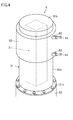
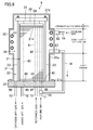
- FIGS. 4 and 5 illustrate the cell stack 6 of the fuel cell 1.
- This cell stack 6 is a so-called stack-type cell stack.
- the cell stack 6 includes a cell stack unit 21, a cover 31, and other elements, and is vertically installed on the support base 22.
- the cell stack unit 21 is located inside the cover 31. Also, a lower end of the cell stack unit 21 is supported on the support base 22, and the cell stack unit 21 extends upward in the vertical direction.
- the cell stack unit 21 is comprised of a plurality of thin plate-like single cells 21a stacked so as to extend in the thickness direction of the single cells 21a, with interconnectors interposed therebetween.
- Each single cell 21a includes a solid electrolyte made of yttria-stabilized zirconia etc.
- An anode electrode is formed on one of surfaces of the solid electrolyte, and a cathode electrode is formed on the other surface of the solid electrolyte.
- An anode-side reaction gap alternates with a cathode-side reaction gap in the gap between each pair of adjacent single cells 21a (not shown).
- the stacked single cells 21a are supported integrally by, e.g., support rods 23 and a holding plate 24.
- the plurality of support rods 23 are provided on the support base 22 to surround the cell stack unit 21, and extend upward in the vertical direction.
- the holding plate 24 is mounted on an upper end surface of the cell stack unit 21.
- a support plate 25 is fastened to an upper end portion, of the support rod 23, that more protrudes than the holding plate 24.
- a spring member 26 is provided on a lower surface of the support plate 25, and the support plate 25 presses the holding plate 24 downwardly through the spring member 26. Consequently, the stacked single cells 21a are compressively secured by the support base 22 and the holding plate 24.
- the cover 31 includes a cylindrical side wall portion 31a larger than the cell stack unit 21, an end wall portion 31b blocking an opening located on an upper end of the side wall portion 31a, and a ring-shaped flange portion 31c protruding outward from a lower end edge of the side wall portion 31a.
- this cover 31 includes a large-diameter portion 32 formed in a certain region of an upper portion of the side wall portion 31 a, having a relatively large diameter, and expanding outward in the diameter direction.
- the region where the large-diameter portion 32 is formed is supposed to be above and away from an anode-side inlet 44 and a cathode-side inlet 45 described later, and is more preferably formed above a middle position that is at an equal distance from the upper and lower ends of the side wall portion 31a.
- the cover 31 is attached to the support base 22 by fastening the flange portion 31c to the support base 22 in a state in which the cover 31 covers the cell stack unit 21.
- the cover 31 extends in the vertical direction along the cell stack unit 21. Consequently, a gap space 33 having a constant width is formed between a side surface of the cell stack unit 21 and an inner surface of the side wall portion 31a.
- a larger space (a heat-absorption space 34) is formed between an upper portion of the side surface of the cell stack unit 21 and an inner surface of the large-diameter portion 32.
- a metal tube 61 is provided in this heat-absorption space 34. This will be described later.
- An anode-side intake manifold 41, a cathode-side intake manifold 42, and an exhaust manifold 43 are formed inside the cell stack unit 21 so as to extend along the stacking direction.
- the anode-side reaction gap of each single cell 21a communicates with the anode-side intake manifold 41 and the exhaust manifold 43.
- the cathode-side reaction gap communicates with the cathode-side intake manifold 42 and the gap space 33.
- the anode-side intake manifold 41 includes the anode-side inlet 44 (an introduction portion) on a lower end surface of the cell stack unit 21, and the cathode-side intake manifold 42 includes the cathode-side inlet 45 (an introduction portion) on the lower end surface of the cell stack unit 21.
- the exhaust manifold 43 includes an anode-side outlet 46 on the lower end surface of the cell stack unit 21.
- the anode-side inlet 44, the cathode-side inlet 45, and the anode-side outlet 46 are adjacent to one another.
- An anode-side inlet hole 47, a cathode-side inlet hole 48, an anode-side outlet hole 49, and a cathode-side outlet hole 50 are cut in an upper surface of the support base 22.
- the anode-side inlet hole 47 communicates with the anode-side intake manifold 41 through the anode-side inlet 44.
- the cathode-side inlet hole 48 communicates with the cathode-side intake manifold 42 through the cathode-side inlet 45.
- the anode-side outlet hole 49 communicates with the exhaust manifold 43 through the anode-side outlet 46.
- the cathode-side outlet hole 50 communicates with the gap space 33.
- the anode-side inlet hole 47 is connected with a downstream end portion of the reactant gas introduction path 10.
- the cathode-side inlet hole 48 is connected with a downstream end portion of the oxidizing agent gas introduction path 11.
- the anode-side outlet hole 49 is connected with an upstream end portion of the anode-side exhaust path 12.
- the cathode-side outlet hole 50 is connected with an upstream end portion of the cathode-side exhaust path 13.
- a high temperature reformed gas is introduced into each anode-side reaction gap through the anode-side inlet hole 47 and the anode-side intake manifold 41, and a heated oxidizing agent gas is introduced into each cathode-side reaction gap through the cathode-side inlet hole 48 and the cathode-side intake manifold 42.
- the cell stack unit 21 is heated by the reformed gas and the heated oxidizing agent gas as heat sources.
- a chemical reaction occurs, in each single cell 21a, between a reformed gas passing through the anode-side reaction gap and a heated oxidizing agent gas passing though the cathode-side reaction gap.
- the reformed gas altered by the chemical reaction is discharged from the cell stack 6 through the exhaust manifold 43.
- the heated oxidizing agent gas altered by the chemical reaction is discharged from the cell stack 6 through the gap space 33.
- the chemical reaction allows each single cell 21a to generate an electromotive force.
- the electric power is generated by extracting that electromotive force.
- electric power is generated at 700°C-900°C, and in particular, efficiently generated at around 800°C.
- Each single cell 21a generates heat by a chemical reaction.
- a cooling control for cooling the cell stack unit 21 as necessary by reducing a temperature of the heated oxidizing agent gas is implemented to maintain a predetermined operating temperature range.
- the joining portion 16 is located in a portion, of the oxidizing agent gas introduction path 11, near the cathode-side inlet hole 48, and in the joining portion 16, a cooling gas joins and mixes with a heated oxidizing agent gas to reduce a temperature of the heated oxidizing agent gas.
- the temperature of the heated oxidizing agent gas is controlled by adjusting the flow rate of the cooling gas.
- the cooling gas introduction path 14 is connected with the joining portion 16 through the metal tube 61 (a heat-absorption part) provided in the heat-absorption space 34, in order to uniformly cool the entirety of the cell stack unit 21 by using the characteristics of the stack-type cell stack 6.
- the metal tube 61 is made of a metal having an excellent thermal conductivity, formed in a spiral shape, and accommodated in the heat-absorption space 34.
- the metal tube 61 is installed around an upper portion of the cell stack unit 21, and faces the cell stack unit 21 with a gap interposed therebetween.
- the metal tube 61 is provided to surround a periphery of the cell stack unit 21, and more particularly, spirally surround the periphery of the cell stack unit 21.
- the word "surround" in this embodiment includes surrounding at least a half of the periphery.
- an upstream connecting portion 62 connected with one end of the metal tube 61 is installed on an upper side of the large-diameter portion 32, and a downstream connecting portion 63 connected with the other end of the metal tube 61 is installed on a lower side of the large-diameter portion 32.
- the metal tube 61 is fixed inside the cover 31. If the metal tube 61 is fixed on the cell stack 6, insulation is required between the metal tube 61 and the cell stack 6. However, if the metal tube 61 is fixed on the cover 31, it is not in contact with the cell stack 6, and no insulation is required. Consequently, the metal tube 61 is positioned with the heat-absorption space 34 kept optimum.
- the metal tube 61 can be positioned in a predetermined position relative to the cell stack 6, and can be covered by the cover 31 in a subsequent stage.
- a downstream end portion of the cooling gas introduction path 14 extending from the branch portion 15 is connected with the upstream connecting portion 62 and communicates with the metal tube 61.
- An upstream end portion of the cooling gas introduction path 14 extending from the joining portion 16 is connected with the downstream connecting portion 63 and communicates with the metal tube 61. Consequently, a cooling gas enters the metal tube 61 from the upstream connecting portion 62, and exits from the downstream connecting portion 63.
- the flow rate control valve 17 When a control for reducing a temperature of the cell stack unit 21 is implemented during a stationary operation, the flow rate control valve 17 is activated to raise the flow rate of a cooling gas. Consequently, a temperature of a heated oxidizing agent gas to be introduced to the cell stack unit 21 is reduced. The heated oxidizing agent gas having a reduced temperature is introduced from the lower end of the cell stack unit 21. Thus, the single cells 21a are cooled in turn from the lower side of the cell stack unit 21, and the heated oxidizing agent gas has a higher temperature as it goes up the cathode-side intake manifold 42.
- each single cell 21a generates heat, which is added to the heated oxidizing agent gas. As a result, the upper portion of the cell stack unit 21 might be cooled insufficiently.
- a cooling gas does not directly join a heated oxidizing agent gas but through the metal tube 61.
- the metal tube 61 is installed in the heat-absorption space 34 provided around the upper portion of the cell stack unit 21, and thus effectively absorbs radiant heat dissipated from the cell stack unit 21. Consequently, in passing through the metal tube 61, the cooling gas absorbs heat on the upper portion of the cell stack unit 21, and thus a temperature of the upper portion of the cell stack unit 21 is relatively reduced.
- the cooling gas efficiently absorbs radiant heat because the metal tube 61 is installed so as to allow the cooling gas to pass around the cell stack 6 from top to bottom and travel a long distance from the high temperature side. Even if a temperature of the cooling gas increases by the heat absorption, it does not increase over a temperature of the heated oxidizing agent gas. Thus, the cooling gas does not lose the intrinsic cooling function.
- the heated oxidizing agent gas is mixed with the cooling gas in the joining portion 16, and the heated oxidizing agent gas having a reduced temperature is introduced into the cell stack unit 21.
- a temperature of the cooling gas rises, a decrease in a temperature of the heated oxidizing agent gas introduced into the cell stack unit 21 is smaller.
- the single cells 21 a located in the lower side of the cell stack unit 21 are cooled gradually.
- the upper portion of the cell stack unit 21 is cooled by the absorption of radiant heat by the cooling gas, and the lower portion of the cell stack unit 21 is gradually cooled by the introduction of the cooling gas having a temperature increased by the absorption of heat by the upper portion of the cell stack unit 21.
- the entirety of the cell stack unit 21 can be uniformly cooled.
- FIGS. 7 and 8 show results of demonstration tests conducted with test equipments.
- FIG. 7 shows a test result of a comparative example.
- a fuel cell of the comparative example has a conventional configuration as illustrated in FIGS. 1 and 2 .
- a periphery of a cell stack unit is simply covered by a cover, and a cooling gas is directly mixed with a heated oxidizing agent gas.
- FIG. 7 shows temperature states immediately before a stationary operation.
- a solid line on the lower side indicates a temperature change in a lower portion of a cell stack unit
- a solid line on the upper side indicates a temperature change in an upper portion of the cell stack unit.
- a broken line indicates a flow rate change in a cooling gas.
- a temperature difference between the upper and lower portions of the cell stack unit was 20°C or more at a stage before an introduction of a cooling gas. Moreover, it was found that, if the flow rate of the cooling gas was raised in response to an increase in a temperature of the upper portion of the cell stack unit, a temperature of the lower portion of the cell stack unit started to decrease, and consequently the temperature difference between the upper and lower portions of the cell stack unit tended to widen.
- FIG. 8 shows a test result of the example.
- the fuel cell of the example has configurations illustrated in FIGS. 3 and 4 , etc.
- the configurations of this example are set to the same as those of the comparative example except the configurations of the cooling gas introduction path and other elements to be compared.
- FIG. 8 shows a temperature change in a stationary operation state at a temperature that is made relatively high for a test purpose.
- a solid line on the lower side indicates a temperature change in the lower portion of the cell stack unit.
- a solid line on the upper side indicates a temperature change in the upper portion of the cell stack unit.
- a broken line indicates a flow rate change in a cooling gas.
- a temperature difference between the upper and lower portions of the cell stack unit was approximately 5°C at a stage before an introduction of a cooling gas. It was found that the temperatures of the upper portion and the lower portion of the cell stack unit increased with the temperature difference therebetween kept approximately constant, and the temperature difference between the upper portion and the lower portion of the cell stack unit did not tend to widen.
- the temperatures of the upper portion and the lower portion of the cell stack unit started to decrease at around 820°C with almost the same timing. At this time, the temperature difference was approximately 10°C.
- FIG. 9 illustrates a variation of the above-described fuel cell 1.
- the locations of a large-diameter portion 32, a metal tube 61, and a heat-absorption space 34 are different from those of the above-described fuel cell 1.
- the large-diameter portion 32 and some other elements are provided to reach the uppermost portion of the cell stack unit 21 (the uppermost layer of the upper portion).
- the large-diameter portion 32 and the other elements tended to cause a widened temperature difference over time between the uppermost layer of the upper portion and the lower portion.
- the uppermost layer of the upper portion was measured as an example of the upper portion.
- the temperature tended to be higher than that of the uppermost layer of the upper portion.
- the flow rate of the cooling gas was adjusted to cool the middle layer, the upper portion (the uppermost layer of the upper portion) was cooled so much that the temperature of the upper portion was decreased to below the temperature of the lower portion.
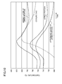
- FIG. 10 is a graph showing such changes as described above, and a broken line indicates a flow rate change in the cooling gas. As shown in FIG. 10 , it was found that if the large-diameter portion 32 and some other elements were provided to reach the uppermost layer of the upper portion, the uppermost layer of the upper portion was cooled so much that a temperature thereof became rather lower than a temperature of the lower portion at some point, and the temperature difference between the uppermost layer of the upper portion and the lower portion tended to widen over time.
- the locations of the large-diameter portion 32 and some other elements were shifted downward, and the upper portion were defined so as to include "the uppermost layer of the upper portion" and "the middle layer of the upper portion.”
- the temperature difference between the uppermost layer of the upper portion and the lower portion did not widen over time by providing the large-diameter portion 32 and some other elements on the middle layer of the upper portion, not on the uppermost layer of the upper portion.
- the entirety of the cell stack unit 21 can be cooled uniformly, and electric power can be generated more efficiently and stably.
- the fuel cell of the present invention is not limited to the above-described embodiments, and may include other various configurations.
- the structure of the heat-absorption part is not limited to the spiral metal piping.
- a double tube structure may be provided on the upper portion of the cover 31 to form an annular space 70 in which a cooling gas flows along the periphery of the cell stack unit.
- the heat-absorption part may be provided in any area as long as it is away from the introduction portion.
- the introduction portion is provided on the upper end of the cell stack unit 21
- the heat-absorption part may be provided in any area as long as it is on the periphery of the lower portion of the cell stack unit 21.
- the heat-absorption part may be provided in any area as long as it is on either one of the peripheries of the upper portion and the lower portion of the cell stack unit 21, or on both the peripheries thereof.
- the cell stack 6 is not limited to a vertical layout, and may be provided in a horizontal layout.
- the cell stack is not limited to a stack-type cell stack, and may be, e.g., a cell stack comprised of a cylindrical cell tube.
- such a cell stack comprised of a cylindrical cell tube includes the following configurations.
- the cell stack comprised of a cylindrical cell tube includes a cylindrical cell unit and electrode terminals connected to both ends of the cell unit.
- a cylindrical inside electrode layer In the cell unit, provided are a cylindrical inside electrode layer, a cylindrical outside electrode layer, and an electrolyte layer provided therebetween.
- the inside electrode layer is a fuel electrode
- the outside electrode layer is an air electrode.
- the inside electrode layer is electrically connected to the electrode terminals.
- a fuel gas passage is formed in a central portion of the electrode terminal.
Landscapes
- Engineering & Computer Science (AREA)
- Chemical & Material Sciences (AREA)
- Life Sciences & Earth Sciences (AREA)
- Manufacturing & Machinery (AREA)
- Sustainable Development (AREA)
- Sustainable Energy (AREA)
- Chemical Kinetics & Catalysis (AREA)
- Electrochemistry (AREA)
- General Chemical & Material Sciences (AREA)
- Combustion & Propulsion (AREA)
- Fuel Cell (AREA)
Abstract
Description
- The present invention relates to a solid oxide fuel cell (SOFC) introducing a reformed gas primarily composed of hydrogen and an oxidizing agent gas from one end to the other end thereof, particularly to a solid oxide fuel cell including a stack-type cell stack, and more particularly to a technique of stabilizing a temperature of a cell stack.
-
FIG. 1 illustrates an exemplary fuel cell. Thisfuel cell 101 is a flat plate solid oxide fuel cell, and generates electric power by using a fuel gas such as a town gas, water, and air as an oxidizing agent. Thefuel cell 101 includes anevaporator 102, anair preheater 103, areformer 104, aburner 105, acell stack 106, and other elements. - The
evaporator 102 heats water to generate a water vapor. The generated water vapor is mixed with a fuel gas that is, e.g., desulfurized, and is subsequently sent to thereformer 104. In thereformer 104, the mixed gas of the fuel gas and the water vapor is reformed into a high temperature reformed gas primarily composed of hydrogen, and is subsequently supplied to thecell stack 106. - After being heated in the
air preheater 103, the air is supplied to thecell stack 106. During a stationary operation, the supply of a high temperature reformed gas and air allows thecell stack 106 to be held in a predetermined operating temperature range between 700°C-900°C. - The
cell stack 106 includes a cell stack unit made by stacking a plurality of single cells formed in thin plate shapes. In thecell stack 106, an electromotive force is generated through a chemical reaction in each single cell while, at a high operating temperature, a reformed gas passes through an anode of the single cell and air passes through a cathode of the single cell. The electromotive force is extracted from each single cell to generate electric power. - Such a cell stack unit is disclosed in, e.g.,
Patent Document 1. - The altered, high temperature reformed gas and air exhausted from the
cell stack 106 are sent to theburner 105. In theburner 105, the reformed gas and the air are mixed to cause combustion, which heats thereformer 104. An exhaust gas generated in theburner 105 is sent to theair preheater 103 to heat air by a heat exchange, and is subsequently exhausted. - Because the chemical reaction that allows for generating an electromotive force is an exothermic reaction, each single cell generates heat once the generation of electric power has been started. Thus, during a stationary operation, a cooling control that allows for a reduction in a temperature of air introduced to the
cell stack 106 is implemented to hold thecell stack 106 in an operating temperature range. - Specifically, a
bypass path 108 that bypasses theair preheater 103 is provided on an oxidizing agentgas introduction path 107 that introduces high temperature air into thecell stack 106 through theair preheater 103. Then, the air heated by theair preheater 103 is mixed with cool air, through thebypass path 108, with the flow rate thereof controlled by a flowrate control valve 109, in order to adjust a temperature of the air introduced to thecell stack 106. - An electric power generating system that implements a control similar to the above is disclosed in, e.g.,
Patent Document 2. -
- Patent Document 1: Japanese Unexamined Patent Publication No.
2011-065909 - Patent Document 2: Japanese Unexamined Patent Publication No.
2009-238623 -
FIG. 2 illustrates an exemplary structure of a cell stack. Acell stack 110 is installed on asupport base 111, and extends upward. A periphery of acell stack unit 112 is covered from a top thereof by atubular cover 113. - A reformed gas and air are introduced from a bottom of the
cell stack unit 112 and distributed to each single cell so as to uniformly spread to the entirecell stack unit 112. The reformed gas and the air distributed to each single cell are altered by a chemical reaction that occurs therebetween, and consequently become an anode off-gas and a cathode off-gas. - The anode off-gas is collected through a predetermined path and the cathode off-gas is collected through a gap between the
cell stack unit 112 and thecover 113. The collected anode off-gas and cathode off-gas are exhausted from a bottom of thecell stack 110 and sent to a burner in order to serve as combustion fuels. - The cell stack has a peculiar problem that a temperature difference easily occurs between upper and lower portions of the cell stack unit.
- More particularly, because a stack-type cell stack takes air from a lower portion thereof, the air cools single cells in turn from the lower side of the cell stack and has a higher temperature as it goes up. In addition, each single cell generates heat, and hot air also rises up. Thus, the upper side of the cell stack unit easily has a higher temperature and is more hardly cooled compared with the lower side of the cell stack unit.
- If a temperature of air introduced is significantly reduced to cool the upper side of the cell stack unit, the lower side of the cell stack unit is excessively cooled and this causes widening of a temperature difference between the upper and lower sides of the cell stack unit.
- It is an object of the present invention to provide a fuel cell including a stack-type cell stack of which an entire cell stack unit can be cooled uniformly.
- The fuel cell disclosed herein is a solid oxide fuel cell. This fuel cell includes a cell stack including an anode electrode and a cathode electrode and comprised of a solid electrolyte, a reformed gas introduction path introducing a reformed gas primarily composed of hydrogen into the cell stack, an oxidizing agent gas introduction path introducing an oxidizing agent gas into the cell stack, and a cooling gas introduction path introducing a cooling gas for reducing a temperature of the oxidizing agent gas into the oxidizing agent gas introduction path.
- A heat-absorption part absorbing heat is provided on a periphery of the cell stack. Also, the cooling gas introduction path is connected with the oxidizing agent gas introduction path through the heat-absorption part.
- In this fuel cell, the heat-absorption part absorbing heat is provided in the periphery of the cell stack, and thus a cooling gas joins an oxidizing agent gas through the heat-absorption part.
- That is, in cooling the cell stack, the heat-absorption part located in a high temperature area of the cell stack is cooled by heat absorption of the cooling gas, and thus the entirety of the cell stack can be cooled uniformly.
- Specifically, the periphery of the cell stack is covered by a tubular cover extending along the surroundings.
- Consequently, a stable flow of an oxidizing agent gas along the cell stack is formed, and thus the temperature of the whole cell stack can be easily controlled.
- More specifically, the cell stack includes a lower end supported by a support base and extends upward in a vertical direction. The introduction portions introducing a reformed gas and an oxidizing agent gas are provided in a lower end portion of the cell stack, and the heat-absorption part is provided in a periphery of an upper portion of the cell stack.
- In this case, the introduction portions are provided in the lower end portion of the cell stack. Thus, the lower side of the cell stack is easily cooled, whereas in particular the upper side of the cell stack easily locally reaches a high temperature due to heat generation by single cells or rise of hot air. Thus, in the cell stack, a temperature difference easily occurs. However, because the heat-absorption part is provided in the periphery of the upper portion of the cell stack, the upper portion of the cell stack is effectively cooled by heat absorption of the cooling gas. Accordingly, the entirety of the cell stack can be uniformly cooled.
- If the upper portion of the cell stack includes the uppermost layer of the upper portion and the middle layer of the upper portion located under the uppermost layer of the upper portion, the heat-absorption part is preferably provided on the middle layer of the upper portion, not on the uppermost layer of the upper portion.
- Although the detail will be described later, this prevents a temperature difference between the uppermost layer and the lower portion from widening over time.
- More specifically, the heat-absorption part is comprised of a metal tube installed in a space in the periphery of the cell stack.
- Accordingly, the cooling gas absorbs radiant heat dissipated from the cell stack through the metal tube, and thus absorbs heat effectively.
- The metal tube is preferably spirally provided in the periphery of the cell stack.
- Accordingly, a long, broad heat transfer surface that allows the cooling gas to absorb heat is achieved, and thus the radiant heat is absorbed more effectively.
- Moreover, an inlet side of the metal tube is preferably more distanced from the introduction portions than an outlet side thereof is.
- Accordingly, the cooling gas travels a long distance from a high temperature side, and thus the radiant heat is absorbed still more effectively.
- According to the fuel cell of the present invention, the entirety of the cell stack can be cooled uniformly, and thus an efficient, stable generation of electric power can be achieved.
-
- [
FIG. 1] FIG. 1 is a schematic view showing a configuration of a conventional fuel cell. - [
FIG. 2] FIG. 2 is a general view of a conventional stack-type cell stack. - [
FIG. 3] FIG. 3 is a general view of a configuration of a fuel cell according to an embodiment. - [
FIG. 4] FIG. 4 is a general perspective view of the cell stack. - [
FIG. 5] FIG. 5 is a general cross sectional view of the cell stack. - [
FIG. 6] FIG. 6 is a general perspective view of a metal tube. - [
FIG. 7] FIG. 7 is a graph showing a test result of a comparative example. - [
FIG. 8] FIG. 8 is a graph showing a test result of the embodiment. - [
FIG. 9] FIG. 9 illustrates a variation of the fuel cell according to the embodiment and corresponds toFIG. 5 . - [
FIG. 10] FIG. 10 is a graph showing temperature changes according to portions of a cell stack unit of the fuel cell according to the embodiment. - [
FIG. 11] FIG. 11 is a graph showing temperature changes according to portions of the cell stack of the fuel cell according to a variation. - [
FIG. 12] FIG. 12 is a general view of a main portion of another variation. - Embodiments of the present invention will be described in detail below with reference to the drawings. The following embodiments are merely preferred examples in nature, and are not intended to limit the present invention, applications thereof, or usage thereof.
-
FIG. 3 illustrates a solid oxide fuel cell (SOFC) 1 according to the present invention. There is not much difference between a basic configuration of thefuel cell 1 and that of thefuel cell 101 shown inFIG. 1 . - In other words, this
fuel cell 1 includes anevaporator 2, anair preheater 3, areformer 4, a burner 5, acell stack 6, and other elements, and generates electric power by using a fuel gas such as a town gas, water, and an oxidizing agent gas and extracting electromotive force from thecell stack 6. - A gas, e.g., air at a low cost, that contains a predetermined amount of oxygen may be used as an oxidizing agent gas. The oxidizing agent gas is not limited to air, and any gas containing oxygen may be used.
- The
evaporator 2 heats water to generate a water vapor. The generated water vapor is mixed with a fuel gas that is, e.g., desulfurized, and is subsequently sent to thereformer 4. In thereformer 4, the mixed gas of a fuel gas and a water vapor is reformed into a gas (a reformed gas), primarily composed of hydrogen, which is introduced into thecell stack 6 through a reactantgas introduction path 10. - The
air preheater 3 heats outside air to generate a high temperature oxidizing agent gas (a heated oxidizing agent gas). The generated heated oxidizing agent gas is introduced into thecell stack 6 through an oxidizing agentgas introduction path 11. A high temperature reformed gas altered in the cell stack 6 (an anode off-gas) is sent to the burner 5 through an anode-side exhaust path 12. A heated oxidizing agent gas altered in the cell stack 6 (a cathode off-gas) is sent to the burner 5 through a cathode-side exhaust path 13. - The anode off-gas contains a redundant fuel. Thus, when the anode off-gas is mixed with the cathode off-gas in the burner 5, combustion occurs and consequently the
reformer 4 is heated. An exhaust gas produced in the burner 5 is sent to theair preheater 3 to heat the oxidizing agent gas, and is subsequently exhausted. - Moreover, also in this
fuel cell 1, in order to control cooling of a temperature of a heated oxidizing agent gas introduced into thecell stack 6, a coolinggas introduction path 14 that bypasses theair preheater 3 is provided on the oxidizing agentgas introduction path 11 that passes through theair preheater 3. - Specifically, an upstream end portion of the cooling
gas introduction path 14 is connected with abranch portion 15, of the oxidizing agentgas introduction path 11, provided upstream of theair preheater 3, and the coolinggas introduction path 14 branches from thebranch portion 15. A downstream end portion of the coolinggas introduction path 14 is connected with a joiningportion 16, of the oxidizing agentgas introduction path 11, provided downstream of theair preheater 3, and the coolinggas introduction path 14 joins the joiningportion 16. - Halfway on the cooling
gas introduction path 14, provided is a flowrate control valve 17 that allows for adjusting a flow rate of a cooling gas flowing in the coolinggas introduction path 14. In thisfuel cell 1, the cooling gas flowing in the coolinggas introduction path 14 is used so that the problem of the temperature difference in thecell stack 6 is solved. - The cooling gas joins air serving as an oxidizing agent gas in the end. Thus, the cooling gas may be a gas, such as nitrogen, that does not contain oxygen. Any gas that does not affect generation of electric power after joining and mixing with another gas may be used. For example, air is easy to handle because it has the same composition as that of an oxidizing agent gas.
-
FIGS. 4 and5 illustrate thecell stack 6 of thefuel cell 1. Thiscell stack 6 is a so-called stack-type cell stack. Thecell stack 6 includes acell stack unit 21, acover 31, and other elements, and is vertically installed on thesupport base 22. Thecell stack unit 21 is located inside thecover 31. Also, a lower end of thecell stack unit 21 is supported on thesupport base 22, and thecell stack unit 21 extends upward in the vertical direction. - As illustrated in
FIG. 5 , similarly to a conventional cell stack unit, thecell stack unit 21 is comprised of a plurality of thin plate-likesingle cells 21a stacked so as to extend in the thickness direction of thesingle cells 21a, with interconnectors interposed therebetween. Eachsingle cell 21a includes a solid electrolyte made of yttria-stabilized zirconia etc. An anode electrode is formed on one of surfaces of the solid electrolyte, and a cathode electrode is formed on the other surface of the solid electrolyte. - An anode-side reaction gap alternates with a cathode-side reaction gap in the gap between each pair of adjacent
single cells 21a (not shown). The stackedsingle cells 21a are supported integrally by, e.g.,support rods 23 and a holdingplate 24. - The plurality of
support rods 23 are provided on thesupport base 22 to surround thecell stack unit 21, and extend upward in the vertical direction. The holdingplate 24 is mounted on an upper end surface of thecell stack unit 21. Asupport plate 25 is fastened to an upper end portion, of thesupport rod 23, that more protrudes than the holdingplate 24. - A
spring member 26 is provided on a lower surface of thesupport plate 25, and thesupport plate 25 presses the holdingplate 24 downwardly through thespring member 26. Consequently, the stackedsingle cells 21a are compressively secured by thesupport base 22 and the holdingplate 24. - The
cover 31 includes a cylindricalside wall portion 31a larger than thecell stack unit 21, anend wall portion 31b blocking an opening located on an upper end of theside wall portion 31a, and a ring-shapedflange portion 31c protruding outward from a lower end edge of theside wall portion 31a. In particular, thiscover 31 includes a large-diameter portion 32 formed in a certain region of an upper portion of theside wall portion 31 a, having a relatively large diameter, and expanding outward in the diameter direction. - The region where the large-
diameter portion 32 is formed is supposed to be above and away from an anode-side inlet 44 and a cathode-side inlet 45 described later, and is more preferably formed above a middle position that is at an equal distance from the upper and lower ends of theside wall portion 31a. - The
cover 31 is attached to thesupport base 22 by fastening theflange portion 31c to thesupport base 22 in a state in which thecover 31 covers thecell stack unit 21. Thecover 31 extends in the vertical direction along thecell stack unit 21. Consequently, agap space 33 having a constant width is formed between a side surface of thecell stack unit 21 and an inner surface of theside wall portion 31a. A larger space (a heat-absorption space 34) is formed between an upper portion of the side surface of thecell stack unit 21 and an inner surface of the large-diameter portion 32. Ametal tube 61 is provided in this heat-absorption space 34. This will be described later. - An anode-
side intake manifold 41, a cathode-side intake manifold 42, and anexhaust manifold 43 are formed inside thecell stack unit 21 so as to extend along the stacking direction. The anode-side reaction gap of eachsingle cell 21a communicates with the anode-side intake manifold 41 and theexhaust manifold 43. The cathode-side reaction gap communicates with the cathode-side intake manifold 42 and thegap space 33. - The anode-
side intake manifold 41 includes the anode-side inlet 44 (an introduction portion) on a lower end surface of thecell stack unit 21, and the cathode-side intake manifold 42 includes the cathode-side inlet 45 (an introduction portion) on the lower end surface of thecell stack unit 21. Theexhaust manifold 43 includes an anode-side outlet 46 on the lower end surface of thecell stack unit 21. The anode-side inlet 44, the cathode-side inlet 45, and the anode-side outlet 46 are adjacent to one another. - An anode-
side inlet hole 47, a cathode-side inlet hole 48, an anode-side outlet hole 49, and a cathode-side outlet hole 50 are cut in an upper surface of thesupport base 22. The anode-side inlet hole 47 communicates with the anode-side intake manifold 41 through the anode-side inlet 44. The cathode-side inlet hole 48 communicates with the cathode-side intake manifold 42 through the cathode-side inlet 45. The anode-side outlet hole 49 communicates with theexhaust manifold 43 through the anode-side outlet 46. The cathode-side outlet hole 50 communicates with thegap space 33. - The anode-
side inlet hole 47 is connected with a downstream end portion of the reactantgas introduction path 10. The cathode-side inlet hole 48 is connected with a downstream end portion of the oxidizing agentgas introduction path 11. The anode-side outlet hole 49 is connected with an upstream end portion of the anode-side exhaust path 12. The cathode-side outlet hole 50 is connected with an upstream end portion of the cathode-side exhaust path 13. - Thus, a high temperature reformed gas is introduced into each anode-side reaction gap through the anode-
side inlet hole 47 and the anode-side intake manifold 41, and a heated oxidizing agent gas is introduced into each cathode-side reaction gap through the cathode-side inlet hole 48 and the cathode-side intake manifold 42. Thecell stack unit 21 is heated by the reformed gas and the heated oxidizing agent gas as heat sources. - When the
cell stack unit 21 is heated, a chemical reaction occurs, in eachsingle cell 21a, between a reformed gas passing through the anode-side reaction gap and a heated oxidizing agent gas passing though the cathode-side reaction gap. The reformed gas altered by the chemical reaction is discharged from thecell stack 6 through theexhaust manifold 43. The heated oxidizing agent gas altered by the chemical reaction is discharged from thecell stack 6 through thegap space 33. - The chemical reaction allows each
single cell 21a to generate an electromotive force. The electric power is generated by extracting that electromotive force. In general, electric power is generated at 700°C-900°C, and in particular, efficiently generated at around 800°C. Thus, it is preferable to hold the entirety of thecell stack unit 21 at around 800°C. - Each
single cell 21a generates heat by a chemical reaction. Thus, in thisfuel cell 1, during a stationary operation, a cooling control for cooling thecell stack unit 21 as necessary by reducing a temperature of the heated oxidizing agent gas is implemented to maintain a predetermined operating temperature range. - Specifically, the joining
portion 16 is located in a portion, of the oxidizing agentgas introduction path 11, near the cathode-side inlet hole 48, and in the joiningportion 16, a cooling gas joins and mixes with a heated oxidizing agent gas to reduce a temperature of the heated oxidizing agent gas. The temperature of the heated oxidizing agent gas is controlled by adjusting the flow rate of the cooling gas. - In this case, in this
fuel cell 1, the coolinggas introduction path 14 is connected with the joiningportion 16 through the metal tube 61 (a heat-absorption part) provided in the heat-absorption space 34, in order to uniformly cool the entirety of thecell stack unit 21 by using the characteristics of the stack-type cell stack 6. - As illustrated in
FIG. 6 , themetal tube 61 is made of a metal having an excellent thermal conductivity, formed in a spiral shape, and accommodated in the heat-absorption space 34. Themetal tube 61 is installed around an upper portion of thecell stack unit 21, and faces thecell stack unit 21 with a gap interposed therebetween. - In other words, the
metal tube 61 is provided to surround a periphery of thecell stack unit 21, and more particularly, spirally surround the periphery of thecell stack unit 21. The word "surround" in this embodiment includes surrounding at least a half of the periphery. - More specifically, an
upstream connecting portion 62 connected with one end of themetal tube 61 is installed on an upper side of the large-diameter portion 32, and a downstream connectingportion 63 connected with the other end of themetal tube 61 is installed on a lower side of the large-diameter portion 32. - The
metal tube 61 is fixed inside thecover 31. If themetal tube 61 is fixed on thecell stack 6, insulation is required between themetal tube 61 and thecell stack 6. However, if themetal tube 61 is fixed on thecover 31, it is not in contact with thecell stack 6, and no insulation is required. Consequently, themetal tube 61 is positioned with the heat-absorption space 34 kept optimum. - Also, even if the
cover 31 is in a different cylindrical shape, themetal tube 61 can be positioned in a predetermined position relative to thecell stack 6, and can be covered by thecover 31 in a subsequent stage. - A downstream end portion of the cooling
gas introduction path 14 extending from thebranch portion 15 is connected with theupstream connecting portion 62 and communicates with themetal tube 61. An upstream end portion of the coolinggas introduction path 14 extending from the joiningportion 16 is connected with the downstream connectingportion 63 and communicates with themetal tube 61. Consequently, a cooling gas enters themetal tube 61 from theupstream connecting portion 62, and exits from the downstream connectingportion 63. - When a control for reducing a temperature of the
cell stack unit 21 is implemented during a stationary operation, the flowrate control valve 17 is activated to raise the flow rate of a cooling gas. Consequently, a temperature of a heated oxidizing agent gas to be introduced to thecell stack unit 21 is reduced. The heated oxidizing agent gas having a reduced temperature is introduced from the lower end of thecell stack unit 21. Thus, thesingle cells 21a are cooled in turn from the lower side of thecell stack unit 21, and the heated oxidizing agent gas has a higher temperature as it goes up the cathode-side intake manifold 42. - Further, because the
cell stack 6 is provided vertically, an upper portion thereof easily has a high temperature due to rise of hot air. Also, eachsingle cell 21a generates heat, which is added to the heated oxidizing agent gas. As a result, the upper portion of thecell stack unit 21 might be cooled insufficiently. - If a temperature of the heated oxidizing agent gas is significantly reduced to cool the upper side of the
cell stack 6, the lower side of thecell stack 6 is cooled excessively, and conversely the temperature difference between the upper and lower sides of thecell stack 6 is increased. This tendency is stronger as the number of stacks of thesingle cells 21 a is larger. - In contrast, in the
fuel cell 1, a cooling gas does not directly join a heated oxidizing agent gas but through themetal tube 61. Themetal tube 61 is installed in the heat-absorption space 34 provided around the upper portion of thecell stack unit 21, and thus effectively absorbs radiant heat dissipated from thecell stack unit 21. Consequently, in passing through themetal tube 61, the cooling gas absorbs heat on the upper portion of thecell stack unit 21, and thus a temperature of the upper portion of thecell stack unit 21 is relatively reduced. - Moreover, the cooling gas efficiently absorbs radiant heat because the
metal tube 61 is installed so as to allow the cooling gas to pass around thecell stack 6 from top to bottom and travel a long distance from the high temperature side. Even if a temperature of the cooling gas increases by the heat absorption, it does not increase over a temperature of the heated oxidizing agent gas. Thus, the cooling gas does not lose the intrinsic cooling function. - Then, the heated oxidizing agent gas is mixed with the cooling gas in the joining
portion 16, and the heated oxidizing agent gas having a reduced temperature is introduced into thecell stack unit 21. However, in comparison with a conventional fuel cell, as a temperature of the cooling gas rises, a decrease in a temperature of the heated oxidizing agent gas introduced into thecell stack unit 21 is smaller. Thus, thesingle cells 21 a located in the lower side of thecell stack unit 21 are cooled gradually. - As can be seen, in this
fuel cell 1, the upper portion of thecell stack unit 21 is cooled by the absorption of radiant heat by the cooling gas, and the lower portion of thecell stack unit 21 is gradually cooled by the introduction of the cooling gas having a temperature increased by the absorption of heat by the upper portion of thecell stack unit 21. Thus, even in the stack-type cell stack 6, the entirety of thecell stack unit 21 can be uniformly cooled. -
FIGS. 7 and8 show results of demonstration tests conducted with test equipments. -
FIG. 7 shows a test result of a comparative example. A fuel cell of the comparative example has a conventional configuration as illustrated inFIGS. 1 and2 . A periphery of a cell stack unit is simply covered by a cover, and a cooling gas is directly mixed with a heated oxidizing agent gas. -
FIG. 7 shows temperature states immediately before a stationary operation. In the figure, a solid line on the lower side indicates a temperature change in a lower portion of a cell stack unit, and a solid line on the upper side indicates a temperature change in an upper portion of the cell stack unit. A broken line indicates a flow rate change in a cooling gas. - It was found that, in the fuel cell of the comparative example, a temperature difference between the upper and lower portions of the cell stack unit was 20°C or more at a stage before an introduction of a cooling gas. Moreover, it was found that, if the flow rate of the cooling gas was raised in response to an increase in a temperature of the upper portion of the cell stack unit, a temperature of the lower portion of the cell stack unit started to decrease, and consequently the temperature difference between the upper and lower portions of the cell stack unit tended to widen.
- Further, it was found that, if the flow rate of the cooling gas was significantly raised, an increase in a temperature of the upper portion of the cell stack unit was decreased, and the temperature tended to be stable at 780-790°C. However, in this case, it was found that the temperature in the lower portion of the cell stack unit sharply decreased to 710°C or less, and consequently the temperature difference between the upper and lower portions of the cell stack unit became 70°C or more.
-
FIG. 8 shows a test result of the example. The fuel cell of the example has configurations illustrated inFIGS. 3 and4 , etc. The configurations of this example are set to the same as those of the comparative example except the configurations of the cooling gas introduction path and other elements to be compared. -
FIG. 8 shows a temperature change in a stationary operation state at a temperature that is made relatively high for a test purpose. Similarly toFIG. 7 , a solid line on the lower side indicates a temperature change in the lower portion of the cell stack unit. A solid line on the upper side indicates a temperature change in the upper portion of the cell stack unit. A broken line indicates a flow rate change in a cooling gas. - It was found that, in the fuel cell of the example, a temperature difference between the upper and lower portions of the cell stack unit was approximately 5°C at a stage before an introduction of a cooling gas. It was found that the temperatures of the upper portion and the lower portion of the cell stack unit increased with the temperature difference therebetween kept approximately constant, and the temperature difference between the upper portion and the lower portion of the cell stack unit did not tend to widen.
- When the cooling gas was introduced and the flow rate thereof was raised, the temperatures of the upper portion and the lower portion of the cell stack unit started to decrease at around 820°C with almost the same timing. At this time, the temperature difference was approximately 10°C.
- It was found that if the flow rate of the cooling gas was held constant from the time of the start of decrease in a temperature, the temperatures of the upper portion and the lower portion of the cell stack unit decreased slowly with the temperature difference of approximately 10°C held, and then tended to converge to 800°C. That is, it was found that the entirety of the cell stack unit could be held at an optimum operating temperature of around 800°C, and thus an electric power could be generated stably.
-
FIG. 9 illustrates a variation of the above-describedfuel cell 1. In the fuel cell of this variation, the locations of a large-diameter portion 32, ametal tube 61, and a heat-absorption space 34 are different from those of the above-describedfuel cell 1. - As illustrated in
FIG. 5 , in the above-describedfuel cell 1, the large-diameter portion 32 and some other elements are provided to reach the uppermost portion of the cell stack unit 21 (the uppermost layer of the upper portion). However, it was found that such layouts of the large-diameter portion 32 and the other elements tended to cause a widened temperature difference over time between the uppermost layer of the upper portion and the lower portion. - In other words, in the above-described example, the uppermost layer of the upper portion was measured as an example of the upper portion. However, it was found that when a temperature of a middle layer of the upper portion was measured alternatively, the temperature tended to be higher than that of the uppermost layer of the upper portion. Then, it was found that when the flow rate of the cooling gas was adjusted to cool the middle layer, the upper portion (the uppermost layer of the upper portion) was cooled so much that the temperature of the upper portion was decreased to below the temperature of the lower portion.
-
FIG. 10 is a graph showing such changes as described above, and a broken line indicates a flow rate change in the cooling gas. As shown inFIG. 10 , it was found that if the large-diameter portion 32 and some other elements were provided to reach the uppermost layer of the upper portion, the uppermost layer of the upper portion was cooled so much that a temperature thereof became rather lower than a temperature of the lower portion at some point, and the temperature difference between the uppermost layer of the upper portion and the lower portion tended to widen over time. - Then, as a result of a study, as illustrated in
FIG. 9 , the locations of the large-diameter portion 32 and some other elements were shifted downward, and the upper portion were defined so as to include "the uppermost layer of the upper portion" and "the middle layer of the upper portion." In this case, as shown in a graph ofFIG. 11 , the temperature difference between the uppermost layer of the upper portion and the lower portion did not widen over time by providing the large-diameter portion 32 and some other elements on the middle layer of the upper portion, not on the uppermost layer of the upper portion. - Thus, according to the fuel cell of this variation, regardless of the lapse of time, the entirety of the
cell stack unit 21 can be cooled uniformly, and electric power can be generated more efficiently and stably. - The fuel cell of the present invention is not limited to the above-described embodiments, and may include other various configurations.
- The structure of the heat-absorption part is not limited to the spiral metal piping. For example, as illustrated in
FIG. 12 , a double tube structure may be provided on the upper portion of thecover 31 to form anannular space 70 in which a cooling gas flows along the periphery of the cell stack unit. - The heat-absorption part may be provided in any area as long as it is away from the introduction portion. For example, if the introduction portion is provided on the upper end of the
cell stack unit 21, the heat-absorption part may be provided in any area as long as it is on the periphery of the lower portion of thecell stack unit 21. In addition, if the introduction portion is provided on an intermediate portion of thecell stack unit 21, the heat-absorption part may be provided in any area as long as it is on either one of the peripheries of the upper portion and the lower portion of thecell stack unit 21, or on both the peripheries thereof. - The
cell stack 6 is not limited to a vertical layout, and may be provided in a horizontal layout. - In addition, the cell stack is not limited to a stack-type cell stack, and may be, e.g., a cell stack comprised of a cylindrical cell tube.
- Specifically, such a cell stack comprised of a cylindrical cell tube includes the following configurations.
- The cell stack comprised of a cylindrical cell tube includes a cylindrical cell unit and electrode terminals connected to both ends of the cell unit. In the cell unit, provided are a cylindrical inside electrode layer, a cylindrical outside electrode layer, and an electrolyte layer provided therebetween. The inside electrode layer is a fuel electrode, and the outside electrode layer is an air electrode. The inside electrode layer is electrically connected to the electrode terminals. A fuel gas passage is formed in a central portion of the electrode terminal.
-
- 1
- Fuel Cell
- 6
- Cell Stack
- 10
- Reactant Gas Introduction Path
- 11
- Oxidizing Agent Gas Introduction Path
- 12
- Anode-Side Exhaust Path
- 13
- Cathode-Side Exhaust Path
- 14
- Cooling Gas Introduction Path
- 21
- Cell Stack Unit
- 21a
- Single Cell
- 22
- Support Base
- 23
- Support Rod
- 31
- Cover
- 32
- Large-Diameter Portion
- 34
- Heat-Absorption Space
- 41
- Anode-Side Intake Manifold
- 42
- Cathode-Side Intake Manifold
- 43
- Exhaust Manifold
- 44
- Anode-Side Inlet (Introduction Portion)
- 45
- Cathode-Side Inlet (Introduction Portion)
- 61
- Metal Tube
- 62
- Upstream Connecting Portion
- 63
- Downstream Connecting Portion
Claims (6)
- A solid oxide fuel cell, comprising:a cell stack including an anode electrode and a cathode electrode and comprised of a solid electrolyte;a reformed gas introduction path introducing a reformed gas primarily composed of hydrogen into the cell stack;an oxidizing agent gas introduction path introducing an oxidizing agent gas into the cell stack; anda cooling gas introduction path introducing a cooling gas for reducing a temperature of the oxidizing agent gas into the oxidizing agent gas introduction path, whereina heat-absorption part absorbing heat is provided on a periphery of the cell stack, andthe cooling gas introduction path is connected with the oxidizing agent gas introduction path through the heat-absorption part.
- The fuel cell of claim 1, wherein
the periphery of the cell stack is covered by a tubular cover extending along the cell stack. - The fuel cell of claim 1 or 2, wherein
the cell stack includes a lower end supported by a support base and extends upward in a vertical direction,
introduction portions introducing the reformed gas and the oxidizing agent gas are provided in a lower end portion of the cell stack, and
the heat-absorption part is provided in a periphery of an upper portion of the cell stack. - The fuel cell of claim 3, wherein
the upper portion of the cell stack includes an uppermost layer of the upper portion and a middle layer of the upper portion located under the uppermost layer of the upper portion, and
the heat-absorption part is provided on the middle layer of the upper portion, not on the uppermost layer of the upper portion. - The fuel cell of any one of claims 1-4, wherein
the heat-absorption part is comprised of a metal tube installed in a space in the periphery of the cell stack. - The fuel cell of claim 5, wherein
the metal tube is spirally provided in the periphery the cell stack.
Applications Claiming Priority (2)
| Application Number | Priority Date | Filing Date | Title |
|---|---|---|---|
| JP2013061858 | 2013-03-25 | ||
| PCT/JP2014/000607 WO2014155928A1 (en) | 2013-03-25 | 2014-02-05 | Fuel cell |
Publications (3)
| Publication Number | Publication Date |
|---|---|
| EP2950377A1 true EP2950377A1 (en) | 2015-12-02 |
| EP2950377A4 EP2950377A4 (en) | 2016-01-13 |
| EP2950377B1 EP2950377B1 (en) | 2017-11-29 |
Family
ID=51622954
Family Applications (1)
| Application Number | Title | Priority Date | Filing Date |
|---|---|---|---|
| EP14773527.8A Active EP2950377B1 (en) | 2013-03-25 | 2014-02-05 | Fuel cell |
Country Status (5)
| Country | Link |
|---|---|
| US (1) | US9666890B2 (en) |
| EP (1) | EP2950377B1 (en) |
| JP (2) | JP6177881B2 (en) |
| CN (1) | CN105009338B (en) |
| WO (1) | WO2014155928A1 (en) |
Families Citing this family (9)
| Publication number | Priority date | Publication date | Assignee | Title |
|---|---|---|---|---|
| CN111278069B (en) * | 2014-04-07 | 2022-05-24 | 交互数字Ce专利控股公司 | Method for controlling handover in mobile communication network and apparatus and system for implementing the same |
| JP6356480B2 (en) * | 2014-05-09 | 2018-07-11 | 東京瓦斯株式会社 | Hot module |
| JP2016171016A (en) * | 2015-03-13 | 2016-09-23 | 富士電機株式会社 | Solid oxide type fuel battery module |
| JP2017183222A (en) * | 2016-03-31 | 2017-10-05 | 本田技研工業株式会社 | Fuel cell system |
| AT519416B1 (en) * | 2016-11-29 | 2019-01-15 | Avl List Gmbh | The fuel cell system |
| FR3087952B1 (en) * | 2018-10-26 | 2021-09-24 | Commissariat Energie Atomique | SOLID OXIDE ELECTROCHEMICAL SYSTEM WITH INTEGRATED HEATING MEDIA |
| CN112397743B (en) * | 2019-08-14 | 2024-10-22 | 全球能源互联网研究院有限公司 | A solid oxide fuel cell connector |
| JP7329396B2 (en) * | 2019-09-11 | 2023-08-18 | 日産自動車株式会社 | fuel cell stack |
| EP4057399A4 (en) * | 2019-11-07 | 2024-08-21 | NISSAN MOTOR Co., Ltd. | FUEL CELL SYSTEM |
Family Cites Families (17)
| Publication number | Priority date | Publication date | Assignee | Title |
|---|---|---|---|---|
| JPH097624A (en) * | 1995-06-19 | 1997-01-10 | Mitsubishi Heavy Ind Ltd | Solid electrolytic fuel cell |
| US6033793A (en) * | 1996-11-01 | 2000-03-07 | Hydrogen Burner Technology, Inc. | Integrated power module |
| JP3925171B2 (en) * | 2000-12-28 | 2007-06-06 | 三菱マテリアル株式会社 | Fuel cell module |
| CA2408041A1 (en) | 2000-12-28 | 2002-11-01 | Mitsubishi Materials Corporation | Fuel cell module and structure for gas supply to fuel cell |
| US6756144B2 (en) * | 2002-01-03 | 2004-06-29 | Hybrid Power Generation Systems, Llc | Integrated recuperation loop in fuel cell stack |
| GB0213561D0 (en) * | 2002-06-13 | 2002-07-24 | Alstom | Fuel cells |
| JP2005078859A (en) | 2003-08-28 | 2005-03-24 | Mitsubishi Heavy Ind Ltd | Fuel cell system |
| JP4461955B2 (en) * | 2004-08-13 | 2010-05-12 | 三菱マテリアル株式会社 | Solid oxide fuel cell |
| JP2007287633A (en) * | 2006-04-20 | 2007-11-01 | Mitsubishi Materials Corp | Fuel cell power generator, control program, and control method |
| JP5242933B2 (en) * | 2007-03-30 | 2013-07-24 | 東邦瓦斯株式会社 | Fuel cell module |
| JP2009054414A (en) * | 2007-08-27 | 2009-03-12 | Mitsubishi Materials Corp | Fuel cell stack |
| JP5185658B2 (en) * | 2008-02-27 | 2013-04-17 | 三菱重工業株式会社 | Combined system |
| JP2009238623A (en) | 2008-03-27 | 2009-10-15 | Hitachi Ltd | Solid oxide fuel cell power generation system and its operation control method |
| JP5350154B2 (en) | 2009-09-18 | 2013-11-27 | 住友精密工業株式会社 | Stacked fuel cell |
| JP5349251B2 (en) * | 2009-10-26 | 2013-11-20 | トヨタ自動車株式会社 | Fuel cell system |
| JP5409333B2 (en) * | 2009-12-24 | 2014-02-05 | 京セラ株式会社 | Fuel cell module and fuel cell device |
| KR20120080881A (en) * | 2011-01-10 | 2012-07-18 | 삼성에스디아이 주식회사 | Fuel cell system and method for controlling reaction condition of fuel in fuel cell |
-
2014
- 2014-02-05 CN CN201480011896.1A patent/CN105009338B/en active Active
- 2014-02-05 JP JP2015507982A patent/JP6177881B2/en active Active
- 2014-02-05 US US14/771,193 patent/US9666890B2/en active Active
- 2014-02-05 EP EP14773527.8A patent/EP2950377B1/en active Active
- 2014-02-05 WO PCT/JP2014/000607 patent/WO2014155928A1/en not_active Ceased
-
2017
- 2017-07-12 JP JP2017136243A patent/JP2017212215A/en active Pending
Also Published As
| Publication number | Publication date |
|---|---|
| EP2950377A4 (en) | 2016-01-13 |
| CN105009338A (en) | 2015-10-28 |
| US9666890B2 (en) | 2017-05-30 |
| US20160013501A1 (en) | 2016-01-14 |
| JPWO2014155928A1 (en) | 2017-02-16 |
| CN105009338B (en) | 2017-05-17 |
| WO2014155928A1 (en) | 2014-10-02 |
| JP6177881B2 (en) | 2017-08-09 |
| EP2950377B1 (en) | 2017-11-29 |
| JP2017212215A (en) | 2017-11-30 |
Similar Documents
| Publication | Publication Date | Title |
|---|---|---|
| EP2950377B1 (en) | Fuel cell | |
| US9240601B2 (en) | Fuel cell module | |
| EP3136487A1 (en) | Hydrogen generating apparatus and fuel cell system | |
| US9343765B2 (en) | Fuel cell module | |
| US9419297B2 (en) | Fuel cell module | |
| US10320016B2 (en) | High-temperature fuel cell system | |
| US9246181B2 (en) | Fuel cell module | |
| JP5109252B2 (en) | Fuel cell | |
| JP5643711B2 (en) | Fuel cell module | |
| US10781100B2 (en) | Fuel cell system | |
| US9972856B2 (en) | Fuel cell module | |
| JP2016139554A (en) | Solid oxide fuel cell device | |
| JP2016051507A (en) | Solid oxide fuel cell apparatus | |
| JP2016051506A (en) | Solid oxide fuel cell apparatus | |
| JP5135823B2 (en) | Fuel cell | |
| KR101387856B1 (en) | Plate type steam reformer for solid oxide fuel cell using natural gas | |
| JP2008117547A (en) | Fuel cell | |
| JP2012220176A (en) | Heat treatment system | |
| US9337506B2 (en) | Fuel cell module | |
| JP6635855B2 (en) | Fuel cell system | |
| JP2013026132A (en) | Fuel cell module | |
| KR101343376B1 (en) | Catalytic oxidizer and fuel cell system having the same | |
| JP2020194757A (en) | Solid oxide fuel battery system | |
| KR20130009721A (en) | Catalytic oxidizer and fuel cell system having the same | |
| JP2016051510A (en) | Solid oxide fuel cell device and manufacturing method thereof |
Legal Events
| Date | Code | Title | Description |
|---|---|---|---|
| PUAI | Public reference made under article 153(3) epc to a published international application that has entered the european phase |
Free format text: ORIGINAL CODE: 0009012 |
|
| 17P | Request for examination filed |
Effective date: 20150828 |
|
| AK | Designated contracting states |
Kind code of ref document: A1 Designated state(s): AL AT BE BG CH CY CZ DE DK EE ES FI FR GB GR HR HU IE IS IT LI LT LU LV MC MK MT NL NO PL PT RO RS SE SI SK SM TR |
|
| AX | Request for extension of the european patent |
Extension state: BA ME |
|
| A4 | Supplementary search report drawn up and despatched |
Effective date: 20151211 |
|
| RIC1 | Information provided on ipc code assigned before grant |
Ipc: H01M 8/04 20060101AFI20151207BHEP Ipc: H01M 8/12 20060101ALI20151207BHEP |
|
| DAX | Request for extension of the european patent (deleted) | ||
| 17Q | First examination report despatched |
Effective date: 20160727 |
|
| GRAP | Despatch of communication of intention to grant a patent |
Free format text: ORIGINAL CODE: EPIDOSNIGR1 |
|
| INTG | Intention to grant announced |
Effective date: 20170411 |
|
| GRAS | Grant fee paid |
Free format text: ORIGINAL CODE: EPIDOSNIGR3 |
|
| GRAJ | Information related to disapproval of communication of intention to grant by the applicant or resumption of examination proceedings by the epo deleted |
Free format text: ORIGINAL CODE: EPIDOSDIGR1 |
|
| GRAL | Information related to payment of fee for publishing/printing deleted |
Free format text: ORIGINAL CODE: EPIDOSDIGR3 |
|
| INTC | Intention to grant announced (deleted) | ||
| GRAP | Despatch of communication of intention to grant a patent |
Free format text: ORIGINAL CODE: EPIDOSNIGR1 |
|
| INTG | Intention to grant announced |
Effective date: 20170922 |
|
| GRAA | (expected) grant |
Free format text: ORIGINAL CODE: 0009210 |
|
| AK | Designated contracting states |
Kind code of ref document: B1 Designated state(s): AL AT BE BG CH CY CZ DE DK EE ES FI FR GB GR HR HU IE IS IT LI LT LU LV MC MK MT NL NO PL PT RO RS SE SI SK SM TR |
|
| REG | Reference to a national code |
Ref country code: CH Ref legal event code: EP |
|
| REG | Reference to a national code |
Ref country code: AT Ref legal event code: REF Ref document number: 951183 Country of ref document: AT Kind code of ref document: T Effective date: 20171215 |
|
| REG | Reference to a national code |
Ref country code: IE Ref legal event code: FG4D |
|
| REG | Reference to a national code |
Ref country code: DE Ref legal event code: R096 Ref document number: 602014017956 Country of ref document: DE |
|
| REG | Reference to a national code |
Ref country code: FR Ref legal event code: PLFP Year of fee payment: 5 |
|
| REG | Reference to a national code |
Ref country code: NL Ref legal event code: MP Effective date: 20171129 |
|
| REG | Reference to a national code |
Ref country code: LT Ref legal event code: MG4D |
|
| REG | Reference to a national code |
Ref country code: AT Ref legal event code: MK05 Ref document number: 951183 Country of ref document: AT Kind code of ref document: T Effective date: 20171129 |
|
| PG25 | Lapsed in a contracting state [announced via postgrant information from national office to epo] |
Ref country code: FI Free format text: LAPSE BECAUSE OF FAILURE TO SUBMIT A TRANSLATION OF THE DESCRIPTION OR TO PAY THE FEE WITHIN THE PRESCRIBED TIME-LIMIT Effective date: 20171129 Ref country code: ES Free format text: LAPSE BECAUSE OF FAILURE TO SUBMIT A TRANSLATION OF THE DESCRIPTION OR TO PAY THE FEE WITHIN THE PRESCRIBED TIME-LIMIT Effective date: 20171129 Ref country code: NO Free format text: LAPSE BECAUSE OF FAILURE TO SUBMIT A TRANSLATION OF THE DESCRIPTION OR TO PAY THE FEE WITHIN THE PRESCRIBED TIME-LIMIT Effective date: 20180228 Ref country code: SE Free format text: LAPSE BECAUSE OF FAILURE TO SUBMIT A TRANSLATION OF THE DESCRIPTION OR TO PAY THE FEE WITHIN THE PRESCRIBED TIME-LIMIT Effective date: 20171129 Ref country code: LT Free format text: LAPSE BECAUSE OF FAILURE TO SUBMIT A TRANSLATION OF THE DESCRIPTION OR TO PAY THE FEE WITHIN THE PRESCRIBED TIME-LIMIT Effective date: 20171129 |
|
| PG25 | Lapsed in a contracting state [announced via postgrant information from national office to epo] |
Ref country code: GR Free format text: LAPSE BECAUSE OF FAILURE TO SUBMIT A TRANSLATION OF THE DESCRIPTION OR TO PAY THE FEE WITHIN THE PRESCRIBED TIME-LIMIT Effective date: 20180301 Ref country code: RS Free format text: LAPSE BECAUSE OF FAILURE TO SUBMIT A TRANSLATION OF THE DESCRIPTION OR TO PAY THE FEE WITHIN THE PRESCRIBED TIME-LIMIT Effective date: 20171129 Ref country code: HR Free format text: LAPSE BECAUSE OF FAILURE TO SUBMIT A TRANSLATION OF THE DESCRIPTION OR TO PAY THE FEE WITHIN THE PRESCRIBED TIME-LIMIT Effective date: 20171129 Ref country code: AT Free format text: LAPSE BECAUSE OF FAILURE TO SUBMIT A TRANSLATION OF THE DESCRIPTION OR TO PAY THE FEE WITHIN THE PRESCRIBED TIME-LIMIT Effective date: 20171129 Ref country code: BG Free format text: LAPSE BECAUSE OF FAILURE TO SUBMIT A TRANSLATION OF THE DESCRIPTION OR TO PAY THE FEE WITHIN THE PRESCRIBED TIME-LIMIT Effective date: 20180228 Ref country code: LV Free format text: LAPSE BECAUSE OF FAILURE TO SUBMIT A TRANSLATION OF THE DESCRIPTION OR TO PAY THE FEE WITHIN THE PRESCRIBED TIME-LIMIT Effective date: 20171129 |
|
| PG25 | Lapsed in a contracting state [announced via postgrant information from national office to epo] |
Ref country code: NL Free format text: LAPSE BECAUSE OF FAILURE TO SUBMIT A TRANSLATION OF THE DESCRIPTION OR TO PAY THE FEE WITHIN THE PRESCRIBED TIME-LIMIT Effective date: 20171129 |
|
| PG25 | Lapsed in a contracting state [announced via postgrant information from national office to epo] |
Ref country code: DK Free format text: LAPSE BECAUSE OF FAILURE TO SUBMIT A TRANSLATION OF THE DESCRIPTION OR TO PAY THE FEE WITHIN THE PRESCRIBED TIME-LIMIT Effective date: 20171129 Ref country code: EE Free format text: LAPSE BECAUSE OF FAILURE TO SUBMIT A TRANSLATION OF THE DESCRIPTION OR TO PAY THE FEE WITHIN THE PRESCRIBED TIME-LIMIT Effective date: 20171129 Ref country code: CY Free format text: LAPSE BECAUSE OF FAILURE TO SUBMIT A TRANSLATION OF THE DESCRIPTION OR TO PAY THE FEE WITHIN THE PRESCRIBED TIME-LIMIT Effective date: 20171129 Ref country code: CZ Free format text: LAPSE BECAUSE OF FAILURE TO SUBMIT A TRANSLATION OF THE DESCRIPTION OR TO PAY THE FEE WITHIN THE PRESCRIBED TIME-LIMIT Effective date: 20171129 Ref country code: SK Free format text: LAPSE BECAUSE OF FAILURE TO SUBMIT A TRANSLATION OF THE DESCRIPTION OR TO PAY THE FEE WITHIN THE PRESCRIBED TIME-LIMIT Effective date: 20171129 |
|
| REG | Reference to a national code |
Ref country code: DE Ref legal event code: R097 Ref document number: 602014017956 Country of ref document: DE |
|
| PG25 | Lapsed in a contracting state [announced via postgrant information from national office to epo] |
Ref country code: RO Free format text: LAPSE BECAUSE OF FAILURE TO SUBMIT A TRANSLATION OF THE DESCRIPTION OR TO PAY THE FEE WITHIN THE PRESCRIBED TIME-LIMIT Effective date: 20171129 Ref country code: IT Free format text: LAPSE BECAUSE OF FAILURE TO SUBMIT A TRANSLATION OF THE DESCRIPTION OR TO PAY THE FEE WITHIN THE PRESCRIBED TIME-LIMIT Effective date: 20171129 Ref country code: PL Free format text: LAPSE BECAUSE OF FAILURE TO SUBMIT A TRANSLATION OF THE DESCRIPTION OR TO PAY THE FEE WITHIN THE PRESCRIBED TIME-LIMIT Effective date: 20171129 Ref country code: SM Free format text: LAPSE BECAUSE OF FAILURE TO SUBMIT A TRANSLATION OF THE DESCRIPTION OR TO PAY THE FEE WITHIN THE PRESCRIBED TIME-LIMIT Effective date: 20171129 |
|
| REG | Reference to a national code |
Ref country code: CH Ref legal event code: PL |
|
| PG25 | Lapsed in a contracting state [announced via postgrant information from national office to epo] |
Ref country code: MC Free format text: LAPSE BECAUSE OF FAILURE TO SUBMIT A TRANSLATION OF THE DESCRIPTION OR TO PAY THE FEE WITHIN THE PRESCRIBED TIME-LIMIT Effective date: 20171129 |
|
| PLBE | No opposition filed within time limit |
Free format text: ORIGINAL CODE: 0009261 |
|
| STAA | Information on the status of an ep patent application or granted ep patent |
Free format text: STATUS: NO OPPOSITION FILED WITHIN TIME LIMIT |
|
| 26N | No opposition filed |
Effective date: 20180830 |
|
| REG | Reference to a national code |
Ref country code: IE Ref legal event code: MM4A |
|
| REG | Reference to a national code |
Ref country code: BE Ref legal event code: MM Effective date: 20180228 |
|
| PG25 | Lapsed in a contracting state [announced via postgrant information from national office to epo] |
Ref country code: LU Free format text: LAPSE BECAUSE OF NON-PAYMENT OF DUE FEES Effective date: 20180205 Ref country code: SI Free format text: LAPSE BECAUSE OF FAILURE TO SUBMIT A TRANSLATION OF THE DESCRIPTION OR TO PAY THE FEE WITHIN THE PRESCRIBED TIME-LIMIT Effective date: 20171129 Ref country code: LI Free format text: LAPSE BECAUSE OF NON-PAYMENT OF DUE FEES Effective date: 20180228 Ref country code: CH Free format text: LAPSE BECAUSE OF NON-PAYMENT OF DUE FEES Effective date: 20180228 |
|
| PG25 | Lapsed in a contracting state [announced via postgrant information from national office to epo] |
Ref country code: IE Free format text: LAPSE BECAUSE OF NON-PAYMENT OF DUE FEES Effective date: 20180205 |
|
| PG25 | Lapsed in a contracting state [announced via postgrant information from national office to epo] |
Ref country code: BE Free format text: LAPSE BECAUSE OF NON-PAYMENT OF DUE FEES Effective date: 20180228 |
|
| PG25 | Lapsed in a contracting state [announced via postgrant information from national office to epo] |
Ref country code: MT Free format text: LAPSE BECAUSE OF NON-PAYMENT OF DUE FEES Effective date: 20180205 |
|
| PG25 | Lapsed in a contracting state [announced via postgrant information from national office to epo] |
Ref country code: TR Free format text: LAPSE BECAUSE OF FAILURE TO SUBMIT A TRANSLATION OF THE DESCRIPTION OR TO PAY THE FEE WITHIN THE PRESCRIBED TIME-LIMIT Effective date: 20171129 |
|
| PG25 | Lapsed in a contracting state [announced via postgrant information from national office to epo] |
Ref country code: PT Free format text: LAPSE BECAUSE OF FAILURE TO SUBMIT A TRANSLATION OF THE DESCRIPTION OR TO PAY THE FEE WITHIN THE PRESCRIBED TIME-LIMIT Effective date: 20171129 |
|
| PG25 | Lapsed in a contracting state [announced via postgrant information from national office to epo] |
Ref country code: MK Free format text: LAPSE BECAUSE OF NON-PAYMENT OF DUE FEES Effective date: 20171129 Ref country code: HU Free format text: LAPSE BECAUSE OF FAILURE TO SUBMIT A TRANSLATION OF THE DESCRIPTION OR TO PAY THE FEE WITHIN THE PRESCRIBED TIME-LIMIT; INVALID AB INITIO Effective date: 20140205 |
|
| PG25 | Lapsed in a contracting state [announced via postgrant information from national office to epo] |
Ref country code: AL Free format text: LAPSE BECAUSE OF FAILURE TO SUBMIT A TRANSLATION OF THE DESCRIPTION OR TO PAY THE FEE WITHIN THE PRESCRIBED TIME-LIMIT Effective date: 20171129 Ref country code: IS Free format text: LAPSE BECAUSE OF FAILURE TO SUBMIT A TRANSLATION OF THE DESCRIPTION OR TO PAY THE FEE WITHIN THE PRESCRIBED TIME-LIMIT Effective date: 20180329 |
|
| REG | Reference to a national code |
Ref country code: DE Ref legal event code: R082 Ref document number: 602014017956 Country of ref document: DE Representative=s name: BRP RENAUD UND PARTNER MBB RECHTSANWAELTE PATE, DE Ref country code: DE Ref legal event code: R081 Ref document number: 602014017956 Country of ref document: DE Owner name: KABUSHIKI KAISHA F.C.C., HAMAMATSU-SHI, JP Free format text: FORMER OWNER: SUMITOMO PRECISION PRODUCTS CO. LTD., AMAGASAKI, HYOGO, JP |
|
| REG | Reference to a national code |
Ref country code: GB Ref legal event code: 732E Free format text: REGISTERED BETWEEN 20210121 AND 20210127 |
|
| PGFP | Annual fee paid to national office [announced via postgrant information from national office to epo] |
Ref country code: DE Payment date: 20231228 Year of fee payment: 11 |
|
| PGFP | Annual fee paid to national office [announced via postgrant information from national office to epo] |
Ref country code: FR Payment date: 20240103 Year of fee payment: 11 |
|
| REG | Reference to a national code |
Ref country code: DE Ref legal event code: R119 Ref document number: 602014017956 Country of ref document: DE |
|
| PG25 | Lapsed in a contracting state [announced via postgrant information from national office to epo] |
Ref country code: DE Free format text: LAPSE BECAUSE OF NON-PAYMENT OF DUE FEES Effective date: 20250902 |
|
| PG25 | Lapsed in a contracting state [announced via postgrant information from national office to epo] |
Ref country code: FR Free format text: LAPSE BECAUSE OF NON-PAYMENT OF DUE FEES Effective date: 20250228 |
|
| PGFP | Annual fee paid to national office [announced via postgrant information from national office to epo] |
Ref country code: GB Payment date: 20260106 Year of fee payment: 13 |