EP2950304A1 - Techniques for arranging stage elements on a stage - Google Patents
Techniques for arranging stage elements on a stage Download PDFInfo
- Publication number
- EP2950304A1 EP2950304A1 EP15165829.1A EP15165829A EP2950304A1 EP 2950304 A1 EP2950304 A1 EP 2950304A1 EP 15165829 A EP15165829 A EP 15165829A EP 2950304 A1 EP2950304 A1 EP 2950304A1
- Authority
- EP
- European Patent Office
- Prior art keywords
- stage
- arrangement
- stage element
- orientation
- elements
- Prior art date
- Legal status (The legal status is an assumption and is not a legal conclusion. Google has not performed a legal analysis and makes no representation as to the accuracy of the status listed.)
- Granted
Links
Images












Classifications
-
- G—PHYSICS
- G05—CONTROLLING; REGULATING
- G05D—SYSTEMS FOR CONTROLLING OR REGULATING NON-ELECTRIC VARIABLES
- G05D3/00—Control of position or direction
-
- G—PHYSICS
- G05—CONTROLLING; REGULATING
- G05B—CONTROL OR REGULATING SYSTEMS IN GENERAL; FUNCTIONAL ELEMENTS OF SUCH SYSTEMS; MONITORING OR TESTING ARRANGEMENTS FOR SUCH SYSTEMS OR ELEMENTS
- G05B15/00—Systems controlled by a computer
- G05B15/02—Systems controlled by a computer electric
-
- H—ELECTRICITY
- H04—ELECTRIC COMMUNICATION TECHNIQUE
- H04R—LOUDSPEAKERS, MICROPHONES, GRAMOPHONE PICK-UPS OR LIKE ACOUSTIC ELECTROMECHANICAL TRANSDUCERS; ELECTRIC HEARING AIDS; PUBLIC ADDRESS SYSTEMS
- H04R29/00—Monitoring arrangements; Testing arrangements
- H04R29/007—Monitoring arrangements; Testing arrangements for public address systems
-
- H—ELECTRICITY
- H04—ELECTRIC COMMUNICATION TECHNIQUE
- H04R—LOUDSPEAKERS, MICROPHONES, GRAMOPHONE PICK-UPS OR LIKE ACOUSTIC ELECTROMECHANICAL TRANSDUCERS; ELECTRIC HEARING AIDS; PUBLIC ADDRESS SYSTEMS
- H04R5/00—Stereophonic arrangements
- H04R5/02—Spatial or constructional arrangements of loudspeakers
-
- H—ELECTRICITY
- H04—ELECTRIC COMMUNICATION TECHNIQUE
- H04S—STEREOPHONIC SYSTEMS
- H04S7/00—Indicating arrangements; Control arrangements, e.g. balance control
- H04S7/30—Control circuits for electronic adaptation of the sound field
-
- H—ELECTRICITY
- H04—ELECTRIC COMMUNICATION TECHNIQUE
- H04S—STEREOPHONIC SYSTEMS
- H04S7/00—Indicating arrangements; Control arrangements, e.g. balance control
- H04S7/30—Control circuits for electronic adaptation of the sound field
- H04S7/302—Electronic adaptation of stereophonic sound system to listener position or orientation
-
- H—ELECTRICITY
- H04—ELECTRIC COMMUNICATION TECHNIQUE
- H04R—LOUDSPEAKERS, MICROPHONES, GRAMOPHONE PICK-UPS OR LIKE ACOUSTIC ELECTROMECHANICAL TRANSDUCERS; ELECTRIC HEARING AIDS; PUBLIC ADDRESS SYSTEMS
- H04R2205/00—Details of stereophonic arrangements covered by H04R5/00 but not provided for in any of its subgroups
- H04R2205/024—Positioning of loudspeaker enclosures for spatial sound reproduction
-
- H—ELECTRICITY
- H04—ELECTRIC COMMUNICATION TECHNIQUE
- H04S—STEREOPHONIC SYSTEMS
- H04S2400/00—Details of stereophonic systems covered by H04S but not provided for in its groups
- H04S2400/11—Positioning of individual sound objects, e.g. moving airplane, within a sound field
-
- H—ELECTRICITY
- H04—ELECTRIC COMMUNICATION TECHNIQUE
- H04S—STEREOPHONIC SYSTEMS
- H04S2420/00—Techniques used stereophonic systems covered by H04S but not provided for in its groups
- H04S2420/05—Application of the precedence or Haas effect, i.e. the effect of first wavefront, in order to improve sound-source localisation
Definitions
- Embodiments of the present invention relate generally to stage setup, and, more specifically, to techniques for arranging stage elements on a stage.
- Live events are a wildly popular form of entertainment. Concerts, plays, stand-up comedy, and other such events draw throngs of people each year. Such events oftentimes take place on a stage that requires a plethora of different types of audio equipment, such as microphones, speakers, monitors, and other stage elements.
- a stage crew arranges the stage elements on the stage to achieve a particular sound quality. The stage crew may then test those elements and rearrange the stage elements, as needed, in an effort to achieve more optimal sound quality.
- the stage crew may rearrange the stage elements to effect different audio capabilities. For example, in a concert, the stage crew may rearrange the stage elements to prepare for a particular song. Alternatively, rearrangement may be needed when stage elements are accidentally moved.
- stage elements must be moved manually.
- Many stage elements are bulky and unwieldy, such as public address (PA) speakers and the like, and therefore difficult or dangerous for laborers to move around on the stage.
- PA public address
- These issues complicate initial setup because many laborers are required to position the various stage elements required for a given event.
- the aforementioned issues are magnified since the audience is required to wait while such rearranging takes place.
- the rearranging needs to happen during the event (without interrupting the flow of the event), and therefore has to be done in a way that the audience does not get distracted from the event.
- stage setup techniques Another problem with conventional stage setup techniques is that optimal sound quality may be difficult or impossible to achieve without precise positioning and orienting of stage elements. With manual setup approaches, such precise arrangements are usually unrealistic. Accordingly, the sound quality associated with a given stage setup is limited by the precision with which the corresponding stage elements can be arranged.
- stage elements is a complicated and error-prone task that requires the cooperative effort of teams of manual laborers.
- Conventional manual approaches may be extremely time consuming and require many iterations before an arrangement having acceptable sound quality can be accomplished.
- One or more embodiments set forth include a non-transitory computer-readable medium storing program instructions that, when executed by a processing unit, cause the processing unit to cause one or more stage elements to be arranged on a stage by performing the steps of determining a current arrangement associated with a first stage element, determining a desired arrangement for the first stage element, and causing an arrangement change to be effected for the first stage element that causes the current arrangement to reflect the desired arrangement.
- At least one advantage of the present invention is that complex arrangements may be accomplished with relative ease compared to prior approaches, since the stage arrangement system described in the present application is capable of autonomously effecting arrangement changes.
- FIG. 1A illustrates a stage arrangement system 100 configured to effect arrangements for a plurality of stage elements on a stage 110, according to various embodiments.
- Stage 110 could reside within an auditorium, concert hall, and so forth, without limitation, and generally represents a performance area for a live event.
- Stage arrangement system 100 is configured to effect different arrangements for the stage elements on stage 110 using various techniques, as described in conjunction with Figures 1A-7 .
- stage arrangement system is configured to generate stage arrangements and calibrate sound output associated with those arrangements, as described in greater detail below in conjunction with Figures 8-13 .
- stage arrangement system 100 is configured to effect stage arrangements for the stage elements on stage 110 in order to reduce feedback, as described in greater detail below in conjunction with Figures 14A-16 .
- the stage elements on stage 110 may include a drum monitor 120, stage box 130, a public address (PA) speaker 140, monitors 150 and 160, another PA speaker 170, and microphones 180 and 190.
- Drum monitor 120 and monitors 150 and 160 are speakers configured to generate audio output for the benefit of performers on stage 110.
- Drum monitors 120 and monitors 150 and 160 may be part of a "foldback" system, as is known in the art.
- PA speakers 140 and 170 are speakers configured to generate audio output for the benefit of the audience.
- Microphones 180 and 190 are audio input devices configured to transduce sound generated by a vocalist, musician, and so forth, without limitation, for output on monitors 150 and/or 160 and PA speakers 140 and/or 170.
- a microphone coupled to a drum set may be configured to transduce sound generated by the drum set for output by drum monitor 120, PA speaker 140 and/or 170.
- stage box 130 may represent a central junction for those various stage elements.
- stage elements described above includes a computing device 102 configured to participate in the functionality of stage arrangement system 100 described herein.
- drum monitor 120 includes computing device 102-0
- stage box 130 includes computing device 102-1
- PA speaker 140 includes computing device 102-2
- monitor 150 includes computing device 102-3
- monitor 160 includes computing device 102-4
- PA speaker 170 includes computing device 102-5.
- Microphones 180 and 190 may also include instances of a computing device 102, although none are shown for the sake of clarity.
- any given stage element may be associated with at least one computing device that resides external to that stage element, where the at least one computing device is configured to implement any of the functionality of computing device(s) 102 described herein.
- Computing devices 102 within the stage elements of stage 110 are configured to interoperate with one another in order to effect different stage arrangements, as described in greater detail below on conjunction with Figures 1B-1C . In doing so, each stage element first participates in a localization procedure.
- localization refers to a process for determining a position and an orientation of a stage element relative to a reference position and orientation, respectively.
- Figures 2A-2B illustrate different techniques for localizing the stage elements on stage 110 relative to a central location
- Figures 3A-3B illustrate different techniques for localizing those stage elements relative to multiple non-centralized locations.
- each stage element effects position and/or orientation changes to assume a new arrangement.
- the new arrangement may reflect a desired arrangement provided by the performers of the live event, an arrangement recommended by the stage crew of stage 110, a default arrangement, or a shared arrangement acquired from a different set of performers.
- a stage element may effect position and/or orientation changes by outputting instructions to a stage hand regarding where to place the stage element and how that element should be oriented. This particular technique is described in greater detail below in conjunction with Figures 4A-4B .
- a stage element may effect position and/or orientation changes via mechanical actuators coupled to the stage element and controlled by a computing device 102 also coupled to thereto.
- the stage element may autonomously perform a repositioning and/or reorienting operation, as described in greater detail below in conjunction with Figures 5A-5B .
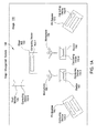
- FIG 1B illustrates stage arrangement system 100 of Figure 1A , including the stage elements of stage 110, during the localization process mentioned above.
- Each stage element resides at a corresponding position and with a particular orientation.
- drum monitor 120 resides at position 122 and with orientation 124
- stage box 130 resides at position 132 with orientation 134
- PA speaker 140 resides at position 142 with orientation 144
- monitor 150 resides at position 152 with orientation 154
- monitor 160 resides at position 162 with orientation 164
- PA speaker 170 resides at position 172 with orientation 174
- microphone 180 resides at position 182 with orientation 184
- microphone 190 resides at position 192 with orientation 194.
- Stage arrangement system 100 is configured to identify the positions and orientations of the stage elements on stage 110 as part of the localization process described above. Persons skilled in the art of sound engineering will readily understand that the arrangement of stage elements on stage 110 is central to achieving a desired sound quality. Upon localizing the stage elements of stage 110, stage arrangement system 100 is configured to rearrange some or all of the stage elements, by repositioning and/or reorienting those elements, in an effort to achieve a particular sound quality, as described in greater detail below in conjunction with Figures 1C .
- Figure 1C illustrates updated positions and orientations that stage arrangement system 100 of Figures 1A-1B generates when rearranging the elements of stage 110, according to various embodiments.
- position 126 and orientation 128 correspond to drum monitor 120
- position 136 and orientation 138 correspond to stage box 130
- position 146 and orientation 148 correspond to PA speaker 140
- position 156 and orientation 158 correspond to monitor 150
- position 166 and orientation 168 correspond to monitor 160
- position 176 and orientation 178 correspond to PA speaker 170
- position 186 and orientation 188 correspond to microphone 180
- position 196 and orientation 198 correspond to microphone 190.
- the new positions and orientations shown in Figures 1C represent a new arrangement for the stage elements on stage 110.
- This new arrangement may allow those stage elements to produce greater sound quality compared to the previous arrangement shown in Figure 1B .
- the new arrangement may reflect the preferences of performers that would use those elements, preferences of the stage crew responsible for stage 110, preferences of other performers who have performed on stage 110 previously, or a default set of preferences, as described below in conjunction with Figures 8-10 .
- the arrangement shown in Figure 1C may be calibrated based on audio feedback captured from the stage elements on stage 110, as described below in conjunction with Figures 11-13 .
- the arrangement shown in Figure 1C may also be implemented in order to reduce feedback, as described in greater detail below in conjunction with Figures 14A-16 .
- Figures 2A-2B illustrate the stage arrangement system of Figures 1A-1C configured to localize the plurality of stage elements relative to a central location, according to various embodiments.
- stage arrangement system 100 localizes the plurality of stage elements on stage 110 relative to stage box 130.
- drum monitor 120 is configured to establish communication link 220 with stage box 130
- PA speaker 140 is configured to establish communication link 240 with stage box 130
- monitor 150 is configured to establish communication link 250 with stage box 130
- monitor 160 is configured to establish communication link 260 with stage box 130
- PA speaker 170 is configured to establish communication link 270 with stage box 130
- microphone 180 is configured to establish communication link 280 with stage box 130
- microphone 190 is configured to establish communication link 290 with stage box 130.
- a computing device 102 within each stage element is configured to establish a communication link with a computing device within stage box 130, although those computing devices have not been shown here for the sake of simplicity.
- Stage arrangement system 100 may rely on the communication links shown in Figure 2A in order to determine the position and/or orientation of each stage element relative to the position and/or orientation of stage box 130.
- drum monitor 120 could establish communication link 220 in order to determine position 122 and orientation 124 of drum monitor 120 relative to position 132 and orientation 134 of stage box 130.
- Each communication link shown could be implemented via any technically feasible type of signal, including radio signals, acoustic signals, optical signals, and so forth, without limitation.
- each such link could constitute multiple signals emanating from different sources on a given stage element.
- drum monitor 120 could include two or more acoustic sources configured to generate different portions of communication link 220.
- Stage box 130 could detect those different portions and triangulate position 122 and orientation 124.
- Stage arrangement system 100 may also include a sensor system configured to directly identify the position and/or orientation of each stage element (i.e. without explicitly communicating with those stage elements), as described below in conjunction with Figure 2B .
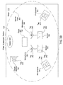
- stage arrangement system 100 relies on a sensor 200 to determine the position and orientation of each stage element on stage 110 by detecting tags coupled to those stage elements.
- drum monitor includes a tag 222
- PA speaker 140 includes a tag 242
- monitors 150 and 160 includes tags 252 and 262, respectively
- PA speaker 170 includes tag 272
- microphones 180 and 190 include tags 282 and 292, respectively.
- Sensor 200 is configured to record sensor data within a sensor field 202 and to identify tags within that sensor field.
- a computing device 102 associated with stage arrangement system 100 then analyzes that sensor data to determine the position and orientation of each such tag and, thus, the position and orientation of each stage element to which a tag is coupled.
- Sensor 200 could be part of any technically feasible type of data capture system, including, for example, an optical data capture system such as an OptiTrack® system, without limitation.
- sensor 200 could include, e.g. radio sensors, acoustic sensors, optical sensors, and other types of sensors, without limitation.
- stage arrangement system 100 may implement either or both of the techniques described in those Figures in order to localize each stage element relative to a central location, be it stage box 130 or sensor 200. Stage arrangement system 100 may also rely on more than one location for localization purposes, as described in greater detail below in conjunction with Figures 3A-3B .
- Figures 3A-3B illustrate the stage arrangement system of Figures 1A-1C configured to localize the plurality of stage elements relative to various decentralized locations, according to various embodiments.
- stage arrangement system 100 of Figures 1A-1C localizes the plurality of stage elements relative to a set of markers.
- stage 110 includes markers 300, 302, 304, and 306. Each marker is positioned at a different corner of stage 110.
- the stage elements on stage 110 are configured to detect one or more of markers 300, 302, 304, and 306 and to determine a position and orientation relative to those markers.
- a computing device 102 within a given stage element may receive signals from one or more of markers 300, 302, 304, and 306 and process those signals to determine a distance and/or angle between the stage element and those markers.
- microphone 190 may includes a computing device 102 configured to receive a signal 301 and to determine, based on that signal, that microphone 190 resides at position 192 with orientation 194.
- PA speaker 170 could rely on computing device 102-5 shown in Figure 1A to process signals 303 and 305 received from markers 303 and 305, respectively, and to determine (e.g., using triangulation) that PA speaker 170 resides at position 172 with orientation 174, without limitation.
- Signals 301, 303, and 305 could be optical signals generated by or reflected by markers 302 and 306, acoustic signals produced by those markers, or other types of detectable signals, without limitation.
- the plurality of stage elements could also perform a localization process relative to one another, as described in greater detail below in conjunction with Figure 3B .
- the stage elements of stage 110 establish an ad-hoc network to perform localization relative to one another.
- the ad-hoc network is formed by communication links 310, 312, 314, 316, 318, 320, 322, 324, and 326 that may be established between stage elements.
- drum monitor 120 i.e., computing device 102-0 within drum monitor 120
- the other communication links may be established between stage elements in the fashion shown in Figure 3B .
- any technically feasible type of signal may implement the aforementioned communication links.
- a given communication link could be implemented by an acoustic signal, a radio signal, an optical signal, and so forth.
- Each stage element is configured to negotiate one or more communication links with neighboring stage elements in order to exchange position and orientation information with those neighboring elements. With this approach, each such stage element may perform a localization process relative to neighboring stage elements and then effect position and orientation changes to assume different arrangements.
- the aforementioned techniques may be practiced without establishing communication links per se.
- the ad-hoc network described above could be generated, for example, via unidirectional links or other data signals that do not explicitly enable bidirectional communication.
- stage arrangement system 100 may implement any technically feasible approach to determining the position and orientation of the stage elements on stage 110.
- stage elements on stage 110 may effect position and orientation changes either indirectly or directly. Specifically, those elements may simply indicate position and orientation changes that should be made (e.g., by a stage hand or other manual laborer, without limitation) as described below in conjunction with Figures 4A-4D . Alternatively, those elements may autonomously perform a repositioning / reorienting process, as described in greater detail below in conjunction with Figures 5A-5B .
- Figures 4A-4B illustrate indicators coupled to a stage element and configured to provide position and orientation information according to which the stage element may be arranged, according to various embodiments.
- a stage element 400 includes indicators 410, 412, 414, and 416 coupled to the front of stage element 400.
- Stage element 400 may be any of the stage elements show on stage 110 in Figures 1A-3B .
- Indicators 410, 412, 414, and 416 provide instructions for positioning and/or orientating stage element 400.
- Indicators 410, 412, 414, and 416 could be, e.g. light-emitting diodes (LED) or another type of luminescent device, without limitation.
- Stage arrangement system 100 is configured to effect position changes to stage element 400 by illuminating one or more of the indicators coupled to that element. A stagehand or other manual laborer may then physically rearrange stage element 400 according to those instructions.
- indicator 410 could indicate that stage element 400 should be moved to the left, while indicator 414 could indicate that stage element 400 should be moved back, without limitation.
- indicators 410, 412, 414, and 416 are coupled to the top of stage element 400, along with indicators 418 and 420.
- Stage arrangement system 100 may effect position changes using indicators 410, 412, 414, and 416 in the fashion described in conjunction with Figure 4A .
- stage arrangement system 100 is configured to effect orientation changes to stage element 400 by illuminating one or more of indicators 418 and 420.
- indicators 418 could indicate that stage element 400 should be rotated clockwise
- indicator 420 could indicate that stage element 400 should be rotated counterclockwise, without limitation.
- Figures 4C-4D illustrate images projected by stage element 400 according to which the stage element may be arranged, according to various embodiments.
- stage element 400 is configured to project position indicators 430, 432, 434, and 436, as well as orientation indicators 438 and 440.
- Stage element 400 includes an image projector 425 capable of generating and projecting images onto stage 110.
- Image projector 425 could be a laser projector or other optical device, for example, and without limitation.
- Position indicators 430, 432, 434, and 436 may provide similar instructions as indicators 410, 412, 414, and 416, respectively, described in conjunction with Figures 4A-4B .
- orientation indicators 438 and 440 may provide similar instructions as indicators 418 and 420, respectively, described in conjunction with Figure 4B .
- a stagehand or other manual laborer may position and orient stage element 400.
- projector 425 is configured to project an outline 450 of the precise position and orientation where stage element 400 should be positioned.
- Outline 450 may have a similar size and shape as a cross-section of stage element 400, so that a stagehand or manual laborer need only place stage element 400 substantially within outline 450 in order to position that element.
- stage element 400 may be repositioned by a stagehand or manual laborer in response to the instructions provided by the various types of indicators discussed therein.
- the instructions provided by those various indicators may be updated based on the current position and orientation of stage element 400 in real time. For example, as stage element 400 shown in Figure 4D is moved towards outline 450, projector 425 could adjust outline 450 to account for the motions of stage element 400. Accordingly, outline 450 would appear static relative to stage 110 despite motions associated with projector 425.
- the indicators discussed herein may be deactivated or may indicate that a successful placement has occurred.
- a stage element on stage 110 may also autonomously perform a repositioning and reorientation process, i.e., independent of a stagehand or manual laborer, as described below in conjunction with Figure 5A-5B .
- Figures 5A-5B illustrate various mechanical actuators coupled to a stage element and configured to cause the stage element to move to a new position and/or orientation, according to various embodiments.
- a stage element 500 includes a carriage 510 configured to roll stage element 500 between different positions and orientations.
- Stage element 500 may be any of the stage elements show on stage 110 in Figures 1A-3B .
- Carriage 510 may include wheels, treads, legs, or other mechanical protrusions configured to provide stage element 500 with locomotive capabilities.
- a computing device within stage element 500 may transmit control signals to carriage 510 in order to perform a repositioning and/or reorienting process.
- stage element 500 does not include mechanical protrusions configured to induce motion, and instead relies on other non-protrusive approaches.
- stage element 500 could include a low-friction bottom surface configured to easily slide across stage 110. Magnets under stage 110 could push or pull stage element 500, thereby inducing motion.
- stage element 500 could include micro-propulsion devices to apply acceleration and deceleration forces to stage element 500.
- stage element 500 includes a vibration actuator 520 configured to move stage element 500 between different positions and orientations using vibrations.
- vibration actuator 520 may be entirely self-contained and need not include mechanical protrusions.
- vibration actuator 520 may include internal gyroscopic elements (none shown) configured to induce vibrations that cause stage element 500 to move in a controlled manner.
- vibration actuator 520 may include one or more linear motors configured to accelerate, and then rapidly decelerate, a mass of any given size, thereby inducing a "jumping" motion in one or more directions. In practice, the kinetic energy of the mass is transferred into stage element 500, thereby causing stage element 500 to lurch forward.
- Figures 1A-5B are meant to illustrate, by way of example, the generic functionality of stage arrangement system 100. As mentioned above, that functionality includes a localization procedure and a repositioning/reorienting procedure. The overall process for rearranging the elements of stage 110 is described in stepwise fashion below in conjunction with Figure 6 .
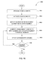
- Figure 6 is a flow diagram of method steps for locating and arranging stage elements on a stage, according to various embodiments. Although the method steps are described in conjunction with the systems of Figures 1-5B , persons skilled in the art will understand that any system configured to perform the method steps, in any order, is within the scope of the present invention.
- stage arrangement system 100 receives arrangement data indicating a desired position and orientation for a stage element on stage 110.
- the arrangement data could originate from a wide variety of different sources, including the performers, the venue sponsoring the performance, and so forth, without limitation.
- stage arrangement system 100 determines the current position and orientation of the stage element.
- Stage arrangement system 100 may localize the stage element relative to a single centralized location (e.g., Figures 2A-2B , without limitation).
- stage arrangement system 100 could localize the stage element relative to one or more decentralized locations (e.g., Figures 3A-3B ).
- stage arrangement system 100 effects changes to the current position and orientation of the stage element to reflect the desired position and orientation indicated by the arrangement data received at step 501.
- stage arrangement system 100 could indirectly effect those changes using indicators (e.g., Figures 4A-4B , without limitation).
- stage arrangement system 100 could effect those changes directly (e.g., Figures 5A-5B , without limitation).
- computing device 102 may perform the method 600 in order to arrange one or more stage elements.
- An exemplary instance of computing device 102 is shown in Figure 7 .
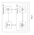
- FIG. 7 is a block diagram of computing device 102 configured to implement one or more aspects of the invention.
- computing device 102 includes a processing unit 700, input/output (I/O) devices 710, and a memory unit 720, coupled together.
- Memory unit 729 includes a software application 721 coupled to a database 722.
- Processing unit 700 may be any technically feasible hardware unit configured to process data, including, without limitation, a central processing unit (CPU), a graphics processing unit (GPU), a parallel processing unit (PPU), an application-specific integrated circuit (ASIC), and so forth.
- Processing unit 700 generally controls the operation of computing device 102, which, in turn, manages the overall functionality of stage arrangement system 100.
- I/O devices 710 include devices configured to receive input, such as a keyboard, a mouse, a microphone, an optical sensor, a radio frequency (RF) receiver, and so forth, without limitation. I/O devices 710 also include devices configured to provide output, such as a speaker, an RF transmitter, an indicator such as that shown in Figures 4A-4B , a projector such as that shown in Figures 4C-4D , a video display, and so forth, without limitation. I/O devices 710 may also include devices configured to both receive input and generate output, such as a touchscreen, a network interface, wireless transceiver, etc., without limitation.
- RF radio frequency
- I/O devices 710 may include devices capable of establishing local area network (LAN) connections and/or wide area network (WAN) connections, thereby providing connectivity to other devices as well as to the Internet.
- Memory unit 720 may be any type of readable and/or writable storage media, including a random access memory (RAM), a hard disk, a combination of memory modules, and so forth, without limitation.
- Software application 721 includes program code that is executable by processing unit 700 to perform the functionality of stage arrangement system 100 described herein.
- Software application 721 may read data from and write data to a database 722.
- the data stored within database 722 may include arrangement data, including position and/or orientation data for stage elements and other localization data, as well as other data needed by stage arrangement system 100.
- Stage arrangement system 100 is capable of effecting arrangements for the stage elements on stage 110 based on a wide variety of different types of arrangement data. As mentioned, that data could reflect preferences of performers, managers of a venue where stage 110 is located, other performers who have performed on stage 110 in the past, and so forth. Stage arrangement system 100 is configured to acquire arrangement data from these different sources and to combine that data, as described below in conjunction with Figures 8-10 . Stage arrangement system 100 may then calibrate that data to optimize that arrangement of elements on stage 110 relative to the acoustic qualities associated with stage 110 and the surrounding venue, as described in greater detail below in conjunction with Figures 11-13 .
- Figure 8 illustrates various data that are processed by an arrangement engine 850 within stage arrangement system 100 to generate combined arrangement data, according to various embodiments.
- arrangement engine 850 receives custom arrangement data 810, venue arrangement data 820, default arrangement data 830, and shared arrangement data 830 and combines those different sets of arrangement data to produce combined arrangement data 860.
- Custom arrangement data 810 reflects a preferred arrangement provided by the performers associated with the live event.
- the performers could have, for example, previously created custom arrangement data 810 based on experience performing at different venues, without limitation.
- Venue arrangement data 820 represents a particular arrangement for stage 110 provided by the venue where stage 110 is located.
- the crew of stage 110 for example, could have created venue arrangement data 820 based on experience arranging elements on stage 110, without limitation.
- Default arrangement data 830 is a standard arrangement that may be selected for the performers according to certain attributes, such as a number of performers, a number of guitars, a number of PA speakers, and so forth, without limitation.
- Shared arrangement data 840 could be provided by another set of performers or retrieved from a cloud-based repository of arrangement data sets, for example, and without limitation.
- Arrangement engine 850 is configured to merge some or all of the arrangement data sets described above through any technically approach to merging data, although one exemplary approach is described below in conjunction with Figures 9A-9B .
- Figure 9A-9B illustrate an exemplary scenario in which arrangement engine 850 of Figure 8 generates combined arrangement data 860, according to various embodiments.
- monitor 150 resides at position 152 with orientation 154 on stage 110, as also shown in Figure 1B .
- a first set of arrangement data could indicate that monitor 150 should reside at position 902 with orientation 904, while a second set of arrangement data could indicate that monitor 150 should reside at position 912 with orientation 914.
- the first and second sets of arrangement data could be any of the arrangement data sets discussed above in conjunction with Figure 8 , without limitation.
- stage arrangement system 100 generates combined arrangement data, based on the first and second sets of arrangement data, indicating that monitor 150 should reside at position 922 with orientation 924.
- Position 922 is located between positions 902 and 912, while orientation 904 resides at an angle between orientation 940 and 914.
- Stage arrangement system 100 may generate position 922 and orientation 924 through a wide variety of different techniques. For example, and without limitation, stage arrangement system 100 could average position 902 with position 912 to generate position 922 and average orientation 904 with orientation 914 to generate orientation 924.
- stage arrangement system 100 could average position 902 with position 912 to generate position 922 and average orientation 904 with orientation 914 to generate orientation 924.
- Persons skilled in the art will understand that the scenario described in conjunction with Figures 9A-9B provided for illustrative purposes only and not meant to be limiting. The techniques described above are also discussed in stepwise fashion below in conjunction with Figure 10 .
- Figure 10 is a flow diagram of method steps for combining arrangement data, according to various embodiments. Although the method steps are described in conjunction with the systems of Figures 1-9B , persons skilled in the art will understand that any system configured to perform the method steps, in any order, is within the scope of the present invention.
- stage arrangement system 100 receives different arrangement data from various sources.
- Stage arrangement system 100 could, for example, receive arrangement data from the performers, the venue, other performers, and so forth, without limitation.
- Each received set of arrangement data may indicate a different position and orientation for each element of stage 110.
- arrangement engine 850 of Figure 8 combines the arrangement data received at step 801 to generate combined arrangement data 860.
- combined arrangement data 860 indicates a position and orientation that is based on the positions and orientations associated with the received arrangement data.
- stage arrangement system 100 adjusts the combined arrangement data, as needed, to repair any problematic positions and/or orientation.
- Such "problematic" positions or orientations could generate feedback, obstruct a view of the performers, and so forth, without limitation.
- Figures 14A-16 described in greater detail below, discuss various approaches for correcting potential feedback issues.
- stage arrangement system 100 may implement a calibration technique in order to fine-tune the arrangement of the stage elements on stage 110 to optimize the sound quality of those elements, as described below.
- Figure 11 illustrates various data that are processed by a calibration engine 1130 within stage arrangement system 100 to generate calibrated arrangement data 1140, according to various embodiments.
- calibration engine 1130 receives configuration data 1110 and calibration data 1120 and, based on the received data, generates calibrated arrangement data 1140.
- Configuration data may represent any of the sets of arrangement data shown in Figure 8 , including, but not limited to, combined arrangement data 860.
- Calibration data 1120 represents data recorded during a sound test of the stage elements on stage 110 when those elements are arranged according to arrangement data 1110.
- Calibration engine 1130 generates calibrated configuration data 1140 by adjusting arrangement data 1140 in order to improve the sound quality of the stage elements on stage 110. Calibration engine 1130 may then update the arrangement of those stage elements, i.e. by effecting position and/or orientation changes in the fashion discussed above, and then re-test those elements to generate new calibration data. Calibration engine 1130 may repeat this process until the sound quality of the elements on stage 110 is acceptable. The testing procedure implemented by calibration engine 1130 is discussed in greater detail below in conjunction with Figures 12A-12B .
- Figures 12A-12B illustrate an exemplary scenario in which the calibration engine of Figure 11 generates calibrated configuration data, according to various embodiments.
- a stage element 1200 resides on stage 110 at a position 1202 with an orientation 1204.
- Position 1202 and orientation 1204 represent the current arraignment of stage element 1200.
- a calibration device 1210 is located off of stage 110 in order to capture sound test data that may reflect sound experienced by the audience during a performance.
- Calibration device 1210 could be, for example, and without limitation, a microphone (or array of microphones) or other transduction device.
- Calibration device 1210 may also include a plurality of microphones distributed over a wide area.
- calibration device 1210 is coupled to an unmanned aerial vehicle (UAV) configured to gather sound test data at a variety of locations.
- UAV unmanned aerial vehicle
- Calibration engine 1130 of Figure 11 is configured to receive calibration data 1120 gathered by calibration device 1210 during the sound test, and to then update the arrangement of stage element 1200 to improve the sound quality generated by stage element 1200, as described below.
- calibration engine 1210 generates calibrated arrangement data that indicates a position 1212 and an orientation 1214.
- Stage arrangement system 100 may then reposition and/or reorient stage element 1200 to assume position 1212 and orientation 1214, potentially improving the sound quality experienced by the audience during performance.
- Figure 13 is a flow diagram of method steps for generating calibrated arrangement data, according to various embodiments. Although the method steps are described in conjunction with the systems of Figures 1-12B , persons skilled in the art will understand that any system configured to perform the method steps, in any order, is within the scope of the present invention.
- a method 1300 begins at step 1301, where calibration engine acquires arrangement data that reflects the current arrangement of the stage elements on stage 110.
- the arrangement data could have been generated, for example, and without limitation, using the techniques described above on conjunction with Figures 8-10 .
- calibration device 1210 records calibration data during a sound test of the stage elements.
- calibration device 1210 may be a microphone coupled to a UAV configured to transduce audio data at a variety of different locations during the sound test.
- calibration engine 1130 generates calibrated arrangement data based on the arrangement data acquired at step 1301 and the calibration data recorded at step 1302.
- the calibrated arrangement data may indicate an arrangement for the stage element that improves sound quality.
- Calibration engine 1130 also effects an arrangement change based on that arrangement data at step 1303.
- calibration engine 1130 repeats the recording of calibration data, similar to step 1302. However, at step 1304 calibration engine 1130 records calibration data that reflects the updated arrangement of elements effected at step 1303.
- calibration engine 1140 determines whether the sound quality associated with the updated calibration data meets a quality metric. If the sound quality is insubstantial, then the method 1300 returns to step 1301. Otherwise, the method 1300 ends.
- any of a human sound engineer, an artificially-intelligent sound engineering system, a musician, a venue director, or other person or automated system determines, at step 1305, whether the quality metric has been met.
- Calibration engine 1140 within stage arrangement system 100 may implement the method 1300 for each different stage element, and may repeat the method 1300 until the sound quality of the stage element on stage 110 is acceptable.
- stage arrangement system 100 may generate arrangements for the stage elements to reflect multiple different sources, and may then calibrate the arrangement of elements to optimize sound quality.
- Feedback is a well-known phenomenon that occurs when an input element receives input from an output element and then transduces that input to the output element. In turn, the output element amplifies, and then outputs the received input. That amplified signal is then received by the input element.
- This cycle is referred to as a feedback loop, and can result in unbounded signal amplification and significant distortion.
- feedback loops are detrimental to sound quality and should be avoided when stage elements are arranged and activated for use.
- the stage arrangement system 100 described thus far is configured to identify potential feedback loops and rearrange the elements of stage 110 to prevent such loops from occurring, as described in greater detail below in conjunction with Figures 14B-16 .
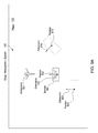
- Figures 14A-14B illustrate exemplary scenarios in which feedback may occur due to a faulty arrangement of stage elements, according to various embodiments.
- microphone 180 resides on stage 110, as also shown in Figures 1A-1C , and receives input within a receptive zone 1480.
- monitor 150 resides proximate to microphone 180 and produces output within sound field 1450 that substantially overlaps with receptive zone 1480.
- microphone 180 and monitor 150 are activated, microphone 180 receives input from sound field 1450, transduces that input to monitor 150, which then amplifies and outputs the received input within sound field 1450.
- the particular arrangement of stage elements shown in Figure 14A causes a feedback loop between microphone 180 and monitor 150.
- Figure 14B illustrates a similar situation whereby PA speaker 140 resides proximate to microphone 180 and produces output within sound field 1440 that substantially overlaps with receptive zone 1480. Similar to above, when microphone 180 and PA speaker 140 150 are activated, microphone 180 receives input from sound field 1440, transduces that input to PA speaker 140, which then amplifies and outputs the received input within sound field 1440.
- the arrangement of stage elements shown in Figure 14B reflects another feedback loop.
- FIG. 14A-14B many such feedback loops may occur between the different input and output elements on stage 110.
- the feedback loops shown in Figures 14A and 14B could occur simultaneously.
- Such feedback loops result due to faulty arrangements of stage elements.
- Stage arrangement system 100 is configured to identify such faulty arrangements, and to then effect rearrangements to reduce the incidence of feedback.
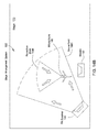
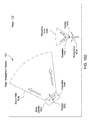
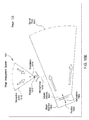
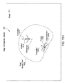
- Figure 15A-15I illustrate various techniques for reducing feedback caused by a faulty arrangement of a generic stage element 1500, according to various embodiments.
- stage element 1500 resides at a position 1502 with an orientation 1504.
- Stage element 1500 represents a generic stage element configured to produce output, such as PA speaker 140 or monitor 150, among others, without limitation.
- Stage element 1500 is positioned proximate to a microphone 1510 that resides at a position 1510 with an orientation 1512.
- Microphone 1510 receives input within receptive zone 1516, which substantially overlaps sound field 1506 associated with stage element 1500.
- This arrangement of stage elements may cause feedback.
- Stage arrangement system 100 is configured to detect this feedback-prone arrangement and effect variation arrangement changes to reduce the incidence of feedback between stage element 1500 and microphone 1510, as described below.
- stage arrangement system 100 determines that stage element 1500 should be moved from position 1502 to position 1503 to create sound field 1507 that does not overlap receptive zone 1516. This new arrangement may reduce feedback between stage element 1500 and microphone 1510. Stage element 1500 may retain the original orientation 1502.
- stage arrangement system 100 determines that stage element 1500 should be reoriented from orientation 1504 to orientation 1505 to create sound field 1509 that does not overlap receptive zone 1516. This new arrangement may reduce feedback between stage element 1500 and microphone 1510. Stage element 1500 may retain the original position 1502.
- stage arrangement system 100 determines that microphone 1510 should be moved from position 1512 to position 1513 so that sound field 1506 does not overlap new receptive zone 1517. This new arrangement may reduce feedback between stage element 1500 and microphone 1510. Stage element 1500 may retain the original position 1502 and orientation 1504, or assume a new position and/or orientation.
- stage element 1500 includes multiple micro-electric-mechanical systems (MEMS) devices 1501.
- MEMS devices 1501 are small actuators, each of which is configured to generate acoustic output. Each MEMS device may be activated separately, and so the sound field generated by stage element 1500 may be precisely controlled. Stage element 1500 may thus generate a sound field 1511 having an arbitrary shape. Accordingly, stage arrangement system 100 may detect potential feedback between stage element 1500 and microphone 1510, and then cause stage element 1500 to "steer" sound field 1511 away from receptive zone 1516. With this approach, stage element 1500 and microphone 1510 need not be repositioned or reoriented to reduce feedback. In various other embodiments, any other technically feasible device for generating a dynamically modifiable sound field may replace MEMS devices 1501.
- Figures 15F-15G illustrate another approach to modifying a sound field.
- stage element 1500 resides at position 1502 with orientation 1504, while microphone 1510 resides at position 1512 with orientation 1514.
- Stage element 1500 generates a polar sound field 1520 that substantially includes microphone 1510.
- the region enclosed by polar sound field 1520 generally reflects an area where the magnitude of sound produced by stage element 1500 exceeds a given threshold value.
- Stage element 1500 is configured to manipulate the size and/or shape of polar sound field 1520 in order to avoid including microphone 1510 in that sound field, thereby reducing the effects of feedback between stage element 1500 and microphone 1510.
- stage element 1500 modifies polar sound field 1520 to generate a deformed polar sound field 1521, which does not include microphone 1510.
- stage element 1500 may include MEMS devices, an array of conventional speakers, or any other technically feasible device capable of generating a dynamically modifiable sound field, without limitation. In this fashion, stage element 1500 may reduce feedback with other elements on stage 110.
- the aforementioned approach may also be practiced to generate polar sound field having asymmetric shapes, as described in greater detail below.
- stage element 1500 generates polar sound field 1522 that, similar to Figure 15F , substantially includes microphone 1510. However, microphone 1510 resides at a slightly different position and orientation within polar sound field 1522 relative to stage element 1500. As such, stage element 1500 is configured to modify the shape of polar sound field 1522 to accommodate these differences.
- stage element 1500 modifies polar sound field 1522 to generate deformed polar sound field 1523 that does not include microphone 1510. As is shown, deformed polar sound field 1523 is asymmetric. As a general matter, stage element 1500 may generate polar sound fields (and other types of sound fields) having any technically feasible size and shape.
- Figure 16 is a flow diagram of method steps for reducing feedback between stage elements, according to various embodiments. Although the method steps are described in conjunction with the systems of Figures 1-15I , persons skilled in the art will understand that any system configured to perform the method steps, in any order, is within the scope of the present invention.
- stage arrangement system 100 arranges the stage elements of stage 110.
- Stage arrangement system 100 may implement any of the techniques described thus far for positioning and orienting each element.
- stage arrangement system 100 activates those stage elements.
- Stage arrangement system 100 could, for example, initiate a sound test at step 1602.
- stage arrangement system 100 detects feedback between an input element and an output element on stage 110.
- stage arrangement system 100 need not activate the stage elements at step 1602 in order to identify feedback, and may simply process the arrangement of elements to identify overlapping sound fields and receptive zones.
- stage arrangement system 100 computes arrangement changes to the output and/or input element in order to reduce feedback.
- the arrangement changes could be similar to those described above in conjunction with Figures 15B-15I , for example, and without limitation.
- stage arrangement system 100 effects those arrangement changes.
- Stage arrangement system 100 could implement any of the techniques described above in conjunction with Figures 4A-5B in order to effect arrangement changes.
- stage arrangement system 100 determines whether the feedback persists. Stage arrangement system 100 could perform another sound test, analyze sound data, or simply analyze the current arrangement of elements to determine whether the feedback persists. If the feedback has been eliminated, then the method ends. Otherwise, the method returns to step 1604 and proceeds as described above.
- Stage arrangement system 100 may implement the method 1600 in advance of a performance or during a performance in order to reduce feedback between stage elements. With this approach, the sound quality of elements on stage 110 may be continuously optimized, improving the experience of the audience and avoiding disturbing feedback.
- a stage arrangement system is configured to arrange stage elements on a stage where a performance is to take place.
- the stage arrangement system is configured to move the stage elements to reflect arrangement data that reflects desired positions and orientations for each stage element.
- the stage arrangement system first localizes one or more stage elements by determining the position and orientation associated with each such element. Then, the stage arrangement system repositions and/or reorients each stage element to comply with the arrangement data.
- Each stage element may indicate position and/or orientation changes to stagehands or manual laborers, who then move each element accordingly. Alternatively, each stage element may autonomously move in order to implement the position and/or orientation changes.
- the arrangement data may be received from a wide variety of sources, including, but not limited to, the performers who will perform using the stage elements, the venue sponsoring the performance, or other performers.
- the stage arrangement system is configured to combine many sets of arrangement data and to then effect position and orientation changes based on combined arrangement data.
- the stage arrangement system may also calibrate the arrangement of elements to reflect an iterative sound test, and may update that arrangement to reduce the incidence of feedback.
- At least one advantage disclosed in the present application is that complex arrangements may be accomplished with relative ease compared to prior approaches, since the stage arrangement system of the present invention is capable of autonomously effecting arrangement changes.
- the stage elements are configured to move autonomously, those elements may be arranged with minimal effort required from manual laborers, decreasing setup time and reducing the risk of bodily injury to those laborers.
- the stage arrangement system may effect arrangement change dynamically, so that the stage elements can be rearranged mid-performance (in preparation for a different performance segment or in response to accidentally perturbed element, among other examples, without limitation).
- the stage arrangement system disclosed herein may optimize the sound quality of a given arrangement by calibrating that arrangement and reducing feedback, thereby simplifying the setup process and improving the audience experience of the performance.
- One embodiment of the invention may be implemented as a program product for use with a computer system.
- the program(s) of the program product define functions of the embodiments (including the methods described herein) and can be contained on a variety of computer-readable storage media.
- Illustrative computer-readable storage media include, but are not limited to: (i) non-writable storage media (e.g., read-only memory devices within a computer such as compact disc read only memory (CD-ROM) disks readable by a CD-ROM drive, flash memory, read only memory (ROM) chips or any type of solid-state non-volatile semiconductor memory) on which information is permanently stored; and (ii) writable storage media (e.g., floppy disks within a diskette drive or hard-disk drive or any type of solid-state random-access semiconductor memory) on which alterable information is stored.
- non-writable storage media e.g., read-only memory devices within a computer such as compact disc read only memory (CD-ROM
Landscapes
- Engineering & Computer Science (AREA)
- Physics & Mathematics (AREA)
- Acoustics & Sound (AREA)
- Signal Processing (AREA)
- General Physics & Mathematics (AREA)
- Automation & Control Theory (AREA)
- Health & Medical Sciences (AREA)
- General Health & Medical Sciences (AREA)
- Otolaryngology (AREA)
- General Engineering & Computer Science (AREA)
- Circuit For Audible Band Transducer (AREA)
Abstract
Description
- Embodiments of the present invention relate generally to stage setup, and, more specifically, to techniques for arranging stage elements on a stage.
- Live events are a wildly popular form of entertainment. Concerts, plays, stand-up comedy, and other such events draw throngs of people each year. Such events oftentimes take place on a stage that requires a plethora of different types of audio equipment, such as microphones, speakers, monitors, and other stage elements. Prior to a given event, a stage crew arranges the stage elements on the stage to achieve a particular sound quality. The stage crew may then test those elements and rearrange the stage elements, as needed, in an effort to achieve more optimal sound quality. During the event, the stage crew may rearrange the stage elements to effect different audio capabilities. For example, in a concert, the stage crew may rearrange the stage elements to prepare for a particular song. Alternatively, rearrangement may be needed when stage elements are accidentally moved.
- One problem with conventional techniques for arranging stage elements is that such elements must be moved manually. Many stage elements are bulky and unwieldy, such as public address (PA) speakers and the like, and therefore difficult or dangerous for laborers to move around on the stage. These issues complicate initial setup because many laborers are required to position the various stage elements required for a given event. When the stage elements need to be rearranged during the event, the aforementioned issues are magnified since the audience is required to wait while such rearranging takes place. Furthermore, in many cases, the rearranging needs to happen during the event (without interrupting the flow of the event), and therefore has to be done in a way that the audience does not get distracted from the event.
- Another problem with conventional stage setup techniques is that optimal sound quality may be difficult or impossible to achieve without precise positioning and orienting of stage elements. With manual setup approaches, such precise arrangements are usually unrealistic. Accordingly, the sound quality associated with a given stage setup is limited by the precision with which the corresponding stage elements can be arranged.
- As the foregoing illustrates, arranging stage elements is a complicated and error-prone task that requires the cooperative effort of teams of manual laborers. Conventional manual approaches may be extremely time consuming and require many iterations before an arrangement having acceptable sound quality can be accomplished.
- One or more embodiments set forth include a non-transitory computer-readable medium storing program instructions that, when executed by a processing unit, cause the processing unit to cause one or more stage elements to be arranged on a stage by performing the steps of determining a current arrangement associated with a first stage element, determining a desired arrangement for the first stage element, and causing an arrangement change to be effected for the first stage element that causes the current arrangement to reflect the desired arrangement.
- At least one advantage of the present invention is that complex arrangements may be accomplished with relative ease compared to prior approaches, since the stage arrangement system described in the present application is capable of autonomously effecting arrangement changes.
- So that the manner in which the recited features of the one more embodiments set forth above can be understood in detail, a more particular description of the one or more embodiments, briefly summarized above, may be had by reference to certain specific embodiments, some of which are illustrated in the appended drawings. It is to be noted, however, that the appended drawings illustrate only typical embodiments and are therefore not to be considered limiting of its scope in any manner, for the scope of the invention subsumes other embodiments as well.
-
Figures 1A-1C illustrate a stage arrangement system configured to effect arrangements for a plurality of stage elements, according to various embodiments; -
Figures 2A-2B illustrate the stage arrangement system ofFigures 1A-1C configured to localize the plurality of stage elements relative to a central location, according to various embodiments; -
Figures 3A-3B illustrate the stage arrangement system ofFigures 1A-1C configured to localize the plurality of stage elements relative to various decentralized locations, according to various embodiments; -
Figures 4A-4B illustrate indicators coupled to a stage element and configured to provide position and orientation information according to which the stage element may be arranged, according to various embodiments; -
Figures 4C-4D illustrate images projected by a stage element according to which the stage element may be arranged, according to various embodiments; -
Figures 5A-5B illustrate various mechanical actuators coupled to a stage element and configured to cause the stage element to move to a new position and/or orientation, according to various embodiments; -
Figure 6 is a flow diagram of method steps for locating and arranging stage elements on a stage, according to various embodiments; -
Figure 7 is a block diagram of a computing device configured to implement one or more aspects of the invention; -
Figure 8 illustrates various data that are processed by an arrangement engine to generate combined arrangement data, according to various embodiments; -
Figure 9A-9B illustrate an exemplary scenario in which the arrangement engine ofFigure 8 generates combined arrangement data, according to various embodiments; -
Figure 10 is a flow diagram of method steps for combining arrangement data, according to various embodiments; -
Figure 11 illustrates various data that are processed by a calibration engine to generate calibrated arrangement data, according to various embodiments; -
Figures 12A-12B illustrate an exemplary scenario in which the calibration engine ofFigure 11 generates calibrated configuration data, according to various embodiments; -
Figure 13 is a flow diagram of method steps for generating calibrated arrangement data, according to various embodiments; -
Figures 14A-14B illustrate exemplary scenarios in which feedback may occur due to a faulty arrangement of stage elements, according to various embodiments; -
Figure 15A-15I illustrate various techniques for reducing feedback caused by a faulty arrangement of a stage element, according to various embodiments; and -
Figure 16 is a flow diagram of method steps for reducing feedback between stage elements, according to various embodiments. - In the following description, numerous specific details are set forth to provide a more thorough understanding of certain specific embodiments. However, it will be apparent to one of skill in the art that other embodiments may be practiced without one or more of these specific details or with additional specific details.
-
Figure 1A illustrates astage arrangement system 100 configured to effect arrangements for a plurality of stage elements on astage 110, according to various embodiments.Stage 110 could reside within an auditorium, concert hall, and so forth, without limitation, and generally represents a performance area for a live event.Stage arrangement system 100 is configured to effect different arrangements for the stage elements onstage 110 using various techniques, as described in conjunction withFigures 1A-7 . In addition, stage arrangement system is configured to generate stage arrangements and calibrate sound output associated with those arrangements, as described in greater detail below in conjunction withFigures 8-13 . Finally,stage arrangement system 100 is configured to effect stage arrangements for the stage elements onstage 110 in order to reduce feedback, as described in greater detail below in conjunction withFigures 14A-16 . - As shown in
Figure 1A , the stage elements onstage 110 may include adrum monitor 120,stage box 130, a public address (PA)speaker 140,monitors PA speaker 170, andmicrophones Drum monitor 120 andmonitors stage 110.Drum monitors 120 andmonitors PA speakers monitors 150 and/or 160 andPA speakers 140 and/or 170. Although not shown, a microphone coupled to a drum set may be configured to transduce sound generated by the drum set for output bydrum monitor 120,PA speaker 140 and/or 170. Each of the stage elements discussed thus far may be coupled tostage box 130, which may represent a central junction for those various stage elements. - Each of the stage elements described above includes a
computing device 102 configured to participate in the functionality ofstage arrangement system 100 described herein. As is shown,drum monitor 120 includes computing device 102-0,stage box 130 includes computing device 102-1,PA speaker 140 includes computing device 102-2,monitor 150 includes computing device 102-3,monitor 160 includes computing device 102-4, andPA speaker 170 includes computing device 102-5.Microphones computing device 102, although none are shown for the sake of clarity. In other embodiments, any given stage element may be associated with at least one computing device that resides external to that stage element, where the at least one computing device is configured to implement any of the functionality of computing device(s) 102 described herein. -
Computing devices 102 within the stage elements ofstage 110 are configured to interoperate with one another in order to effect different stage arrangements, as described in greater detail below on conjunction withFigures 1B-1C . In doing so, each stage element first participates in a localization procedure. In the context of this disclosure, "localization" refers to a process for determining a position and an orientation of a stage element relative to a reference position and orientation, respectively.Figures 2A-2B illustrate different techniques for localizing the stage elements onstage 110 relative to a central location, whileFigures 3A-3B illustrate different techniques for localizing those stage elements relative to multiple non-centralized locations. - Once the stage elements have been localized, each stage element effects position and/or orientation changes to assume a new arrangement. The new arrangement may reflect a desired arrangement provided by the performers of the live event, an arrangement recommended by the stage crew of
stage 110, a default arrangement, or a shared arrangement acquired from a different set of performers. A stage element may effect position and/or orientation changes by outputting instructions to a stage hand regarding where to place the stage element and how that element should be oriented. This particular technique is described in greater detail below in conjunction withFigures 4A-4B . Alternatively, a stage element may effect position and/or orientation changes via mechanical actuators coupled to the stage element and controlled by acomputing device 102 also coupled to thereto. With this alternative technique, the stage element may autonomously perform a repositioning and/or reorienting operation, as described in greater detail below in conjunction withFigures 5A-5B . - Although the present disclosure provides alternative implementations for many of the techniques described herein, the essential localization and rearrangement process is described below in conjunction with
Figures 1B-1C . -
Figure 1B illustratesstage arrangement system 100 ofFigure 1A , including the stage elements ofstage 110, during the localization process mentioned above. Each stage element resides at a corresponding position and with a particular orientation. As shown by way of example and not limitation, drum monitor 120 resides atposition 122 and withorientation 124,stage box 130 resides atposition 132 withorientation 134,PA speaker 140 resides atposition 142 withorientation 144, monitor 150 resides atposition 152 withorientation 154, monitor 160 resides atposition 162 withorientation 164,PA speaker 170 resides atposition 172 withorientation 174,microphone 180 resides atposition 182 withorientation 184, andmicrophone 190 resides atposition 192 withorientation 194. -
Stage arrangement system 100 is configured to identify the positions and orientations of the stage elements onstage 110 as part of the localization process described above. Persons skilled in the art of sound engineering will readily understand that the arrangement of stage elements onstage 110 is central to achieving a desired sound quality. Upon localizing the stage elements ofstage 110,stage arrangement system 100 is configured to rearrange some or all of the stage elements, by repositioning and/or reorienting those elements, in an effort to achieve a particular sound quality, as described in greater detail below in conjunction withFigures 1C . -
Figure 1C illustrates updated positions and orientations that stagearrangement system 100 ofFigures 1A-1B generates when rearranging the elements ofstage 110, according to various embodiments. As shown,position 126 andorientation 128 correspond to drummonitor 120,position 136 andorientation 138 correspond to stagebox 130,position 146 andorientation 148 correspond toPA speaker 140, position 156 and orientation 158 correspond to monitor 150,position 166 andorientation 168 correspond to monitor 160,position 176 andorientation 178 correspond toPA speaker 170,position 186 andorientation 188 correspond tomicrophone 180, andposition 196 andorientation 198 correspond tomicrophone 190. - The new positions and orientations shown in
Figures 1C represent a new arrangement for the stage elements onstage 110. This new arrangement may allow those stage elements to produce greater sound quality compared to the previous arrangement shown inFigure 1B . Among other things, the new arrangement may reflect the preferences of performers that would use those elements, preferences of the stage crew responsible forstage 110, preferences of other performers who have performed onstage 110 previously, or a default set of preferences, as described below in conjunction withFigures 8-10 . In addition, the arrangement shown inFigure 1C may be calibrated based on audio feedback captured from the stage elements onstage 110, as described below in conjunction withFigures 11-13 . The arrangement shown inFigure 1C may also be implemented in order to reduce feedback, as described in greater detail below in conjunction withFigures 14A-16 . - Persons skilled in the art will understand that the particular set of stage elements shown in
Figures 1A-1B along with the corresponding positions and orientations shown inFigures 1B-1C constitute exemplary arrangements of those stage elements that are not meant to limit the scope of the invention. As a general matter, the techniques described herein may be applied to any set of stage elements to (i) localize those elements and (ii) achieve any particular arrangement. -
Figures 2A-2B illustrate the stage arrangement system ofFigures 1A-1C configured to localize the plurality of stage elements relative to a central location, according to various embodiments. - In
Figure 2A ,stage arrangement system 100 localizes the plurality of stage elements onstage 110 relative to stagebox 130. As shown, drum monitor 120 is configured to establishcommunication link 220 withstage box 130,PA speaker 140 is configured to establishcommunication link 240 withstage box 130, monitor 150 is configured to establishcommunication link 250 withstage box 130, monitor 160 is configured to establishcommunication link 260 withstage box 130,PA speaker 170 is configured to establishcommunication link 270 withstage box 130,microphone 180 is configured to establishcommunication link 280 withstage box 130, andmicrophone 190 is configured to establishcommunication link 290 withstage box 130. In operation, acomputing device 102 within each stage element is configured to establish a communication link with a computing device withinstage box 130, although those computing devices have not been shown here for the sake of simplicity. -
Stage arrangement system 100 may rely on the communication links shown inFigure 2A in order to determine the position and/or orientation of each stage element relative to the position and/or orientation ofstage box 130. For example, and without limitation, drum monitor 120 could establishcommunication link 220 in order to determineposition 122 andorientation 124 of drum monitor 120 relative to position 132 andorientation 134 ofstage box 130. Each communication link shown could be implemented via any technically feasible type of signal, including radio signals, acoustic signals, optical signals, and so forth, without limitation. In addition, each such link could constitute multiple signals emanating from different sources on a given stage element. For example, drum monitor 120 could include two or more acoustic sources configured to generate different portions ofcommunication link 220.Stage box 130 could detect those different portions and triangulateposition 122 andorientation 124.Stage arrangement system 100 may also include a sensor system configured to directly identify the position and/or orientation of each stage element (i.e. without explicitly communicating with those stage elements), as described below in conjunction withFigure 2B . - In
Figure 2B ,stage arrangement system 100 relies on asensor 200 to determine the position and orientation of each stage element onstage 110 by detecting tags coupled to those stage elements. As shown, drum monitor includes atag 222,PA speaker 140 includes atag 242, monitors 150 and 160 includestags PA speaker 170 includestag 272, andmicrophones tags 282 and 292, respectively.Sensor 200 is configured to record sensor data within asensor field 202 and to identify tags within that sensor field. Acomputing device 102 associated withstage arrangement system 100 then analyzes that sensor data to determine the position and orientation of each such tag and, thus, the position and orientation of each stage element to which a tag is coupled.Sensor 200 could be part of any technically feasible type of data capture system, including, for example, an optical data capture system such as an OptiTrack® system, without limitation. As a general matter,sensor 200 could include, e.g. radio sensors, acoustic sensors, optical sensors, and other types of sensors, without limitation. - Referring generally to
Figure 2A-2B ,stage arrangement system 100 may implement either or both of the techniques described in those Figures in order to localize each stage element relative to a central location, be itstage box 130 orsensor 200.Stage arrangement system 100 may also rely on more than one location for localization purposes, as described in greater detail below in conjunction withFigures 3A-3B . -
Figures 3A-3B illustrate the stage arrangement system ofFigures 1A-1C configured to localize the plurality of stage elements relative to various decentralized locations, according to various embodiments. - In
Figure 3A ,stage arrangement system 100 ofFigures 1A-1C localizes the plurality of stage elements relative to a set of markers. As shown,stage 110 includesmarkers stage 110. The stage elements onstage 110 are configured to detect one or more ofmarkers computing device 102 within a given stage element may receive signals from one or more ofmarkers - For example, and without limitation,
microphone 190 may includes acomputing device 102 configured to receive asignal 301 and to determine, based on that signal, thatmicrophone 190 resides atposition 192 withorientation 194. Likewise,PA speaker 170 could rely on computing device 102-5 shown inFigure 1A to processsignals markers PA speaker 170 resides atposition 172 withorientation 174, without limitation.Signals markers Figure 3B . - In
Figure 3B , the stage elements ofstage 110 establish an ad-hoc network to perform localization relative to one another. As shown, the ad-hoc network is formed bycommunication links communication links PA speaker 140 andmicrophone 180. The other communication links may be established between stage elements in the fashion shown inFigure 3B . - Any technically feasible type of signal may implement the aforementioned communication links. For example, and without limitation, a given communication link could be implemented by an acoustic signal, a radio signal, an optical signal, and so forth. Each stage element is configured to negotiate one or more communication links with neighboring stage elements in order to exchange position and orientation information with those neighboring elements. With this approach, each such stage element may perform a localization process relative to neighboring stage elements and then effect position and orientation changes to assume different arrangements. In further embodiments, the aforementioned techniques may be practiced without establishing communication links per se. In particular, the ad-hoc network described above could be generated, for example, via unidirectional links or other data signals that do not explicitly enable bidirectional communication.
- Referring generally to
Figures 2A-3B , the techniques described in those Figures reflect exemplary approaches to performing a localization process relative to a central location or multiple decentralized locations, and are not meant to limit the scope of the invention. As a general matter,stage arrangement system 100 may implement any technically feasible approach to determining the position and orientation of the stage elements onstage 110. - Once localized, the stage elements on
stage 110 may effect position and orientation changes either indirectly or directly. Specifically, those elements may simply indicate position and orientation changes that should be made (e.g., by a stage hand or other manual laborer, without limitation) as described below in conjunction withFigures 4A-4D . Alternatively, those elements may autonomously perform a repositioning / reorienting process, as described in greater detail below in conjunction withFigures 5A-5B . -
Figures 4A-4B illustrate indicators coupled to a stage element and configured to provide position and orientation information according to which the stage element may be arranged, according to various embodiments. - In
Figure 4A , astage element 400 includesindicators stage element 400.Stage element 400 may be any of the stage elements show onstage 110 inFigures 1A-3B .Indicators stage element 400.Indicators Stage arrangement system 100 is configured to effect position changes to stageelement 400 by illuminating one or more of the indicators coupled to that element. A stagehand or other manual laborer may then physically rearrangestage element 400 according to those instructions. For example,indicator 410 could indicate thatstage element 400 should be moved to the left, whileindicator 414 could indicate thatstage element 400 should be moved back, without limitation. - In
Figure 4B ,indicators stage element 400, along withindicators Stage arrangement system 100 may effect positionchanges using indicators Figure 4A . In addition,stage arrangement system 100 is configured to effect orientation changes to stageelement 400 by illuminating one or more ofindicators indicators 418 could indicate thatstage element 400 should be rotated clockwise, whileindicator 420 could indicate thatstage element 400 should be rotated counterclockwise, without limitation. -
Figures 4C-4D illustrate images projected bystage element 400 according to which the stage element may be arranged, according to various embodiments. - In
Figure 4C ,stage element 400 is configured to projectposition indicators orientation indicators Stage element 400 includes animage projector 425 capable of generating and projecting images ontostage 110.Image projector 425 could be a laser projector or other optical device, for example, and without limitation.Position indicators indicators Figures 4A-4B . In addition,orientation indicators indicators Figure 4B . Based on the directives provided by the indicators shown inFigure 4C , a stagehand or other manual laborer may position and orientstage element 400. - In
Figure 4D ,projector 425 is configured to project anoutline 450 of the precise position and orientation wherestage element 400 should be positioned. Outline 450 may have a similar size and shape as a cross-section ofstage element 400, so that a stagehand or manual laborer need onlyplace stage element 400 substantially withinoutline 450 in order to position that element. - Referring generally to
Figures 4A-4D ,stage element 400 may be repositioned by a stagehand or manual laborer in response to the instructions provided by the various types of indicators discussed therein. Asstage element 400 is physically moved, the instructions provided by those various indicators may be updated based on the current position and orientation ofstage element 400 in real time. For example, asstage element 400 shown inFigure 4D is moved towardsoutline 450,projector 425 could adjustoutline 450 to account for the motions ofstage element 400. Accordingly,outline 450 would appear static relative to stage 110 despite motions associated withprojector 425. Oncestage element 400 has been repositioned or reoriented to the location determined bystage arrangement system 100, the indicators discussed herein may be deactivated or may indicate that a successful placement has occurred. A stage element onstage 110 may also autonomously perform a repositioning and reorientation process, i.e., independent of a stagehand or manual laborer, as described below in conjunction withFigure 5A-5B . -
Figures 5A-5B illustrate various mechanical actuators coupled to a stage element and configured to cause the stage element to move to a new position and/or orientation, according to various embodiments. - In
Figure 5A , astage element 500 includes a carriage 510 configured to rollstage element 500 between different positions and orientations.Stage element 500 may be any of the stage elements show onstage 110 inFigures 1A-3B . Carriage 510 may include wheels, treads, legs, or other mechanical protrusions configured to providestage element 500 with locomotive capabilities. Whenstage arrangement system 100 localizesstage element 500, and then determines a new position and/or orientation for that stage element, a computing device withinstage element 500 may transmit control signals to carriage 510 in order to perform a repositioning and/or reorienting process. - In one embodiment,
stage element 500 does not include mechanical protrusions configured to induce motion, and instead relies on other non-protrusive approaches. For example,stage element 500 could include a low-friction bottom surface configured to easily slide acrossstage 110. Magnets understage 110 could push or pullstage element 500, thereby inducing motion. Alternatively,stage element 500 could include micro-propulsion devices to apply acceleration and deceleration forces to stageelement 500. - In
Figure 5B ,stage element 500 includes a vibration actuator 520 configured to movestage element 500 between different positions and orientations using vibrations. Unlike carriage 510 described above, vibration actuator 520 may be entirely self-contained and need not include mechanical protrusions. Instead, vibration actuator 520 may include internal gyroscopic elements (none shown) configured to induce vibrations that causestage element 500 to move in a controlled manner. Alternatively, vibration actuator 520 may include one or more linear motors configured to accelerate, and then rapidly decelerate, a mass of any given size, thereby inducing a "jumping" motion in one or more directions. In practice, the kinetic energy of the mass is transferred intostage element 500, thereby causingstage element 500 to lurch forward. - Referring generally to
Figures 5A-5B , the techniques described in those Figures are provided for exemplary purposes only in order to illustrate different approaches for autonomously repositioning and reorienting a stage element. Persons skilled in the art will understand that other techniques are equally applicable to the present invention, and that any technically feasible approach to autonomously moving an object falls within the scope of the present invention. -
Figures 1A-5B are meant to illustrate, by way of example, the generic functionality ofstage arrangement system 100. As mentioned above, that functionality includes a localization procedure and a repositioning/reorienting procedure. The overall process for rearranging the elements ofstage 110 is described in stepwise fashion below in conjunction withFigure 6 . -
Figure 6 is a flow diagram of method steps for locating and arranging stage elements on a stage, according to various embodiments. Although the method steps are described in conjunction with the systems ofFigures 1-5B , persons skilled in the art will understand that any system configured to perform the method steps, in any order, is within the scope of the present invention. - As shown, a
method 500 begins at step 501, wherestage arrangement system 100 receives arrangement data indicating a desired position and orientation for a stage element onstage 110. The arrangement data could originate from a wide variety of different sources, including the performers, the venue sponsoring the performance, and so forth, without limitation. At step 502,stage arrangement system 100 determines the current position and orientation of the stage element.Stage arrangement system 100 may localize the stage element relative to a single centralized location (e.g.,Figures 2A-2B , without limitation). Alternatively,stage arrangement system 100 could localize the stage element relative to one or more decentralized locations (e.g.,Figures 3A-3B ). - At step 503,
stage arrangement system 100 effects changes to the current position and orientation of the stage element to reflect the desired position and orientation indicated by the arrangement data received at step 501. In doing so,stage arrangement system 100 could indirectly effect those changes using indicators (e.g.,Figures 4A-4B , without limitation). Alternatively,stage arrangement system 100 could effect those changes directly (e.g.,Figures 5A-5B , without limitation). - Any technically feasible device capable of localizing stage elements and effecting arrangement changes for those elements may implement the
method 600. For example, computing device 102 (several instances of which are shown inFigure 1A ) may perform themethod 600 in order to arrange one or more stage elements. An exemplary instance ofcomputing device 102 is shown inFigure 7 . -
Figure 7 is a block diagram ofcomputing device 102 configured to implement one or more aspects of the invention. As shown,computing device 102 includes aprocessing unit 700, input/output (I/O)devices 710, and amemory unit 720, coupled together. Memory unit 729 includes asoftware application 721 coupled to adatabase 722.Processing unit 700 may be any technically feasible hardware unit configured to process data, including, without limitation, a central processing unit (CPU), a graphics processing unit (GPU), a parallel processing unit (PPU), an application-specific integrated circuit (ASIC), and so forth.Processing unit 700 generally controls the operation ofcomputing device 102, which, in turn, manages the overall functionality ofstage arrangement system 100. - I/
O devices 710 include devices configured to receive input, such as a keyboard, a mouse, a microphone, an optical sensor, a radio frequency (RF) receiver, and so forth, without limitation. I/O devices 710 also include devices configured to provide output, such as a speaker, an RF transmitter, an indicator such as that shown inFigures 4A-4B , a projector such as that shown inFigures 4C-4D , a video display, and so forth, without limitation. I/O devices 710 may also include devices configured to both receive input and generate output, such as a touchscreen, a network interface, wireless transceiver, etc., without limitation. I/O devices 710 may include devices capable of establishing local area network (LAN) connections and/or wide area network (WAN) connections, thereby providing connectivity to other devices as well as to the Internet.Memory unit 720 may be any type of readable and/or writable storage media, including a random access memory (RAM), a hard disk, a combination of memory modules, and so forth, without limitation. -
Software application 721 includes program code that is executable by processingunit 700 to perform the functionality ofstage arrangement system 100 described herein.Software application 721 may read data from and write data to adatabase 722. The data stored withindatabase 722 may include arrangement data, including position and/or orientation data for stage elements and other localization data, as well as other data needed bystage arrangement system 100. -
Stage arrangement system 100 is capable of effecting arrangements for the stage elements onstage 110 based on a wide variety of different types of arrangement data. As mentioned, that data could reflect preferences of performers, managers of a venue wherestage 110 is located, other performers who have performed onstage 110 in the past, and so forth.Stage arrangement system 100 is configured to acquire arrangement data from these different sources and to combine that data, as described below in conjunction withFigures 8-10 .Stage arrangement system 100 may then calibrate that data to optimize that arrangement of elements onstage 110 relative to the acoustic qualities associated withstage 110 and the surrounding venue, as described in greater detail below in conjunction withFigures 11-13 . -
Figure 8 illustrates various data that are processed by anarrangement engine 850 withinstage arrangement system 100 to generate combined arrangement data, according to various embodiments. As shown,arrangement engine 850 receives custom arrangement data 810,venue arrangement data 820,default arrangement data 830, and sharedarrangement data 830 and combines those different sets of arrangement data to produce combinedarrangement data 860. - Custom arrangement data 810 reflects a preferred arrangement provided by the performers associated with the live event. The performers could have, for example, previously created custom arrangement data 810 based on experience performing at different venues, without limitation.
Venue arrangement data 820 represents a particular arrangement forstage 110 provided by the venue wherestage 110 is located. The crew ofstage 110, for example, could have createdvenue arrangement data 820 based on experience arranging elements onstage 110, without limitation.Default arrangement data 830 is a standard arrangement that may be selected for the performers according to certain attributes, such as a number of performers, a number of guitars, a number of PA speakers, and so forth, without limitation. Sharedarrangement data 840 could be provided by another set of performers or retrieved from a cloud-based repository of arrangement data sets, for example, and without limitation.Arrangement engine 850 is configured to merge some or all of the arrangement data sets described above through any technically approach to merging data, although one exemplary approach is described below in conjunction withFigures 9A-9B . -
Figure 9A-9B illustrate an exemplary scenario in whicharrangement engine 850 ofFigure 8 generates combinedarrangement data 860, according to various embodiments. - As shown in
Figure 9A , monitor 150 resides atposition 152 withorientation 154 onstage 110, as also shown inFigure 1B . A first set of arrangement data could indicate that monitor 150 should reside atposition 902 withorientation 904, while a second set of arrangement data could indicate that monitor 150 should reside atposition 912 withorientation 914. The first and second sets of arrangement data could be any of the arrangement data sets discussed above in conjunction withFigure 8 , without limitation. - As shown in
Figure 9B ,stage arrangement system 100 generates combined arrangement data, based on the first and second sets of arrangement data, indicating thatmonitor 150 should reside atposition 922 withorientation 924.Position 922 is located betweenpositions orientation 904 resides at an angle betweenorientation 940 and 914.Stage arrangement system 100 may generateposition 922 andorientation 924 through a wide variety of different techniques. For example, and without limitation,stage arrangement system 100 could averageposition 902 withposition 912 to generateposition 922 andaverage orientation 904 withorientation 914 to generateorientation 924. Persons skilled in the art will understand that the scenario described in conjunction withFigures 9A-9B provided for illustrative purposes only and not meant to be limiting. The techniques described above are also discussed in stepwise fashion below in conjunction withFigure 10 . -
Figure 10 is a flow diagram of method steps for combining arrangement data, according to various embodiments. Although the method steps are described in conjunction with the systems ofFigures 1-9B , persons skilled in the art will understand that any system configured to perform the method steps, in any order, is within the scope of the present invention. - As shown, a
method 1000 begins atstep 1001, whereinstage arrangement system 100 receives different arrangement data from various sources.Stage arrangement system 100 could, for example, receive arrangement data from the performers, the venue, other performers, and so forth, without limitation. Each received set of arrangement data may indicate a different position and orientation for each element ofstage 110. - At
step 1002,arrangement engine 850 ofFigure 8 combines the arrangement data received at step 801 to generate combinedarrangement data 860. For a given stage element, combinedarrangement data 860 indicates a position and orientation that is based on the positions and orientations associated with the received arrangement data. - At
step 1003,stage arrangement system 100 adjusts the combined arrangement data, as needed, to repair any problematic positions and/or orientation. Such "problematic" positions or orientations could generate feedback, obstruct a view of the performers, and so forth, without limitation.Figures 14A-16 , described in greater detail below, discuss various approaches for correcting potential feedback issues. - Once
arrangement engine 850 has combined the various sets of arrangement data,stage arrangement system 100 may implement a calibration technique in order to fine-tune the arrangement of the stage elements onstage 110 to optimize the sound quality of those elements, as described below. -
Figure 11 illustrates various data that are processed by acalibration engine 1130 withinstage arrangement system 100 to generate calibratedarrangement data 1140, according to various embodiments. As shown,calibration engine 1130 receivesconfiguration data 1110 andcalibration data 1120 and, based on the received data, generates calibratedarrangement data 1140. Configuration data may represent any of the sets of arrangement data shown inFigure 8 , including, but not limited to, combinedarrangement data 860.Calibration data 1120 represents data recorded during a sound test of the stage elements onstage 110 when those elements are arranged according toarrangement data 1110. -
Calibration engine 1130 generates calibratedconfiguration data 1140 by adjustingarrangement data 1140 in order to improve the sound quality of the stage elements onstage 110.Calibration engine 1130 may then update the arrangement of those stage elements, i.e. by effecting position and/or orientation changes in the fashion discussed above, and then re-test those elements to generate new calibration data.Calibration engine 1130 may repeat this process until the sound quality of the elements onstage 110 is acceptable. The testing procedure implemented bycalibration engine 1130 is discussed in greater detail below in conjunction withFigures 12A-12B . -
Figures 12A-12B illustrate an exemplary scenario in which the calibration engine ofFigure 11 generates calibrated configuration data, according to various embodiments. - In
Figure 12A , astage element 1200 resides onstage 110 at aposition 1202 with anorientation 1204.Position 1202 andorientation 1204 represent the current arraignment ofstage element 1200. Acalibration device 1210 is located off ofstage 110 in order to capture sound test data that may reflect sound experienced by the audience during a performance.Calibration device 1210 could be, for example, and without limitation, a microphone (or array of microphones) or other transduction device.Calibration device 1210 may also include a plurality of microphones distributed over a wide area. In one embodiment,calibration device 1210 is coupled to an unmanned aerial vehicle (UAV) configured to gather sound test data at a variety of locations. -
Calibration engine 1130 ofFigure 11 is configured to receivecalibration data 1120 gathered bycalibration device 1210 during the sound test, and to then update the arrangement ofstage element 1200 to improve the sound quality generated bystage element 1200, as described below. - In
Figure 12B ,calibration engine 1210 generates calibrated arrangement data that indicates aposition 1212 and anorientation 1214.Stage arrangement system 100 may then reposition and/or reorientstage element 1200 to assumeposition 1212 andorientation 1214, potentially improving the sound quality experienced by the audience during performance. -
Figure 13 is a flow diagram of method steps for generating calibrated arrangement data, according to various embodiments. Although the method steps are described in conjunction with the systems ofFigures 1-12B , persons skilled in the art will understand that any system configured to perform the method steps, in any order, is within the scope of the present invention. - As shown, a
method 1300 begins atstep 1301, where calibration engine acquires arrangement data that reflects the current arrangement of the stage elements onstage 110. The arrangement data could have been generated, for example, and without limitation, using the techniques described above on conjunction withFigures 8-10 . - At
step 1302,calibration device 1210 records calibration data during a sound test of the stage elements. In one embodiment,calibration device 1210 may be a microphone coupled to a UAV configured to transduce audio data at a variety of different locations during the sound test. - At
step 1303,calibration engine 1130 generates calibrated arrangement data based on the arrangement data acquired atstep 1301 and the calibration data recorded atstep 1302. The calibrated arrangement data may indicate an arrangement for the stage element that improves sound quality.Calibration engine 1130 also effects an arrangement change based on that arrangement data atstep 1303. - At
step 1304,calibration engine 1130 repeats the recording of calibration data, similar tostep 1302. However, atstep 1304calibration engine 1130 records calibration data that reflects the updated arrangement of elements effected atstep 1303. - At
step 1305,calibration engine 1140 determines whether the sound quality associated with the updated calibration data meets a quality metric. If the sound quality is insubstantial, then themethod 1300 returns to step 1301. Otherwise, themethod 1300 ends. As a general matter, any of a human sound engineer, an artificially-intelligent sound engineering system, a musician, a venue director, or other person or automated system determines, atstep 1305, whether the quality metric has been met.Calibration engine 1140 withinstage arrangement system 100 may implement themethod 1300 for each different stage element, and may repeat themethod 1300 until the sound quality of the stage element onstage 110 is acceptable. - By implementing the techniques described in conjunction with
Figures 8-13 ,stage arrangement system 100 may generate arrangements for the stage elements to reflect multiple different sources, and may then calibrate the arrangement of elements to optimize sound quality. - Feedback is a well-known phenomenon that occurs when an input element receives input from an output element and then transduces that input to the output element. In turn, the output element amplifies, and then outputs the received input. That amplified signal is then received by the input element. This cycle is referred to as a feedback loop, and can result in unbounded signal amplification and significant distortion. As a general matter, feedback loops are detrimental to sound quality and should be avoided when stage elements are arranged and activated for use. The
stage arrangement system 100 described thus far is configured to identify potential feedback loops and rearrange the elements ofstage 110 to prevent such loops from occurring, as described in greater detail below in conjunction withFigures 14B-16 . -
Figures 14A-14B illustrate exemplary scenarios in which feedback may occur due to a faulty arrangement of stage elements, according to various embodiments. - As shown in
Figure 14A ,microphone 180 resides onstage 110, as also shown inFigures 1A-1C , and receives input within areceptive zone 1480. However, monitor 150 resides proximate tomicrophone 180 and produces output withinsound field 1450 that substantially overlaps withreceptive zone 1480. Whenmicrophone 180 and monitor 150 are activated,microphone 180 receives input fromsound field 1450, transduces that input to monitor 150, which then amplifies and outputs the received input withinsound field 1450. The particular arrangement of stage elements shown inFigure 14A causes a feedback loop betweenmicrophone 180 and monitor 150. -
Figure 14B illustrates a similar situation wherebyPA speaker 140 resides proximate tomicrophone 180 and produces output withinsound field 1440 that substantially overlaps withreceptive zone 1480. Similar to above, whenmicrophone 180 andPA speaker 140 150 are activated,microphone 180 receives input fromsound field 1440, transduces that input toPA speaker 140, which then amplifies and outputs the received input withinsound field 1440. The arrangement of stage elements shown inFigure 14B reflects another feedback loop. - Referring generally to
Figures 14A-14B , many such feedback loops may occur between the different input and output elements onstage 110. For example, and without limitation the feedback loops shown inFigures 14A and14B could occur simultaneously. Such feedback loops result due to faulty arrangements of stage elements.Stage arrangement system 100 is configured to identify such faulty arrangements, and to then effect rearrangements to reduce the incidence of feedback.Figure 15A-15I illustrate various techniques for reducing feedback caused by a faulty arrangement of ageneric stage element 1500, according to various embodiments. - In
Figure 15A ,stage element 1500 resides at aposition 1502 with anorientation 1504.Stage element 1500 represents a generic stage element configured to produce output, such asPA speaker 140 or monitor 150, among others, without limitation.Stage element 1500 is positioned proximate to amicrophone 1510 that resides at aposition 1510 with anorientation 1512.Microphone 1510 receives input withinreceptive zone 1516, which substantially overlapssound field 1506 associated withstage element 1500. This arrangement of stage elements may cause feedback.Stage arrangement system 100 is configured to detect this feedback-prone arrangement and effect variation arrangement changes to reduce the incidence of feedback betweenstage element 1500 andmicrophone 1510, as described below. - In
Figure 15B ,stage arrangement system 100 determines thatstage element 1500 should be moved fromposition 1502 toposition 1503 to createsound field 1507 that does not overlapreceptive zone 1516. This new arrangement may reduce feedback betweenstage element 1500 andmicrophone 1510.Stage element 1500 may retain theoriginal orientation 1502. - In
Figure 15C ,stage arrangement system 100 determines thatstage element 1500 should be reoriented fromorientation 1504 toorientation 1505 to createsound field 1509 that does not overlapreceptive zone 1516. This new arrangement may reduce feedback betweenstage element 1500 andmicrophone 1510.Stage element 1500 may retain theoriginal position 1502. - Referring to
Figure 15B and15C , persons skilled in the art will recognize that the aforementioned techniques for repositioning and reorientingstage element 1500, respectively, may be combined or practiced separately. - In
Figure 15D ,stage arrangement system 100 determines thatmicrophone 1510 should be moved fromposition 1512 toposition 1513 so thatsound field 1506 does not overlap new receptive zone 1517. This new arrangement may reduce feedback betweenstage element 1500 andmicrophone 1510.Stage element 1500 may retain theoriginal position 1502 andorientation 1504, or assume a new position and/or orientation. - In
Figure 15E ,stage element 1500 includes multiple micro-electric-mechanical systems (MEMS)devices 1501.MEMS devices 1501 are small actuators, each of which is configured to generate acoustic output. Each MEMS device may be activated separately, and so the sound field generated bystage element 1500 may be precisely controlled.Stage element 1500 may thus generate asound field 1511 having an arbitrary shape. Accordingly,stage arrangement system 100 may detect potential feedback betweenstage element 1500 andmicrophone 1510, and then causestage element 1500 to "steer"sound field 1511 away fromreceptive zone 1516. With this approach,stage element 1500 andmicrophone 1510 need not be repositioned or reoriented to reduce feedback. In various other embodiments, any other technically feasible device for generating a dynamically modifiable sound field may replaceMEMS devices 1501.Figures 15F-15G illustrate another approach to modifying a sound field. - In
Figure 15F ,stage element 1500 resides atposition 1502 withorientation 1504, whilemicrophone 1510 resides atposition 1512 withorientation 1514.Stage element 1500 generates apolar sound field 1520 that substantially includesmicrophone 1510. The region enclosed bypolar sound field 1520 generally reflects an area where the magnitude of sound produced bystage element 1500 exceeds a given threshold value.Stage element 1500 is configured to manipulate the size and/or shape ofpolar sound field 1520 in order to avoid includingmicrophone 1510 in that sound field, thereby reducing the effects of feedback betweenstage element 1500 andmicrophone 1510. - In
Figure 15G ,stage element 1500 modifiespolar sound field 1520 to generate a deformedpolar sound field 1521, which does not includemicrophone 1510. As previously mentioned,stage element 1500 may include MEMS devices, an array of conventional speakers, or any other technically feasible device capable of generating a dynamically modifiable sound field, without limitation. In this fashion,stage element 1500 may reduce feedback with other elements onstage 110. The aforementioned approach may also be practiced to generate polar sound field having asymmetric shapes, as described in greater detail below. - In
Figure 15H ,stage element 1500 generatespolar sound field 1522 that, similar toFigure 15F , substantially includesmicrophone 1510. However,microphone 1510 resides at a slightly different position and orientation withinpolar sound field 1522 relative to stageelement 1500. As such,stage element 1500 is configured to modify the shape ofpolar sound field 1522 to accommodate these differences. - In
Figure 15I ,stage element 1500 modifiespolar sound field 1522 to generate deformedpolar sound field 1523 that does not includemicrophone 1510. As is shown, deformedpolar sound field 1523 is asymmetric. As a general matter,stage element 1500 may generate polar sound fields (and other types of sound fields) having any technically feasible size and shape. - Referring generally to
Figures 15A-15I , persons skilled in the art will understand that the various techniques described thus far may be combined in any technically feasible fashion. For example, an array of speakers (i.e. non-MEMS speakers) may be implemented instead ofMEMS device 1501. In addition, the aforementioned techniques are provided for illustrative purposes only, and not meant to limit the scope of the present invention. Generally, any system configured to (i) detect arrangements that may cause feedback and to then (ii) effect arrangement changes to reduce that feedback, falls within the scope of the present invention. This essential approach is described in stepwise fashion below in conjunction withFigure 16 . -
Figure 16 is a flow diagram of method steps for reducing feedback between stage elements, according to various embodiments. Although the method steps are described in conjunction with the systems ofFigures 1-15I , persons skilled in the art will understand that any system configured to perform the method steps, in any order, is within the scope of the present invention. - As shown a
method 1600 begins atstep 1601, wherestage arrangement system 100 arranges the stage elements ofstage 110.Stage arrangement system 100 may implement any of the techniques described thus far for positioning and orienting each element. Atstep 1602,stage arrangement system 100 activates those stage elements.Stage arrangement system 100 could, for example, initiate a sound test atstep 1602. - At
step 1603,stage arrangement system 100 detects feedback between an input element and an output element onstage 110. In one embodiment,stage arrangement system 100 need not activate the stage elements atstep 1602 in order to identify feedback, and may simply process the arrangement of elements to identify overlapping sound fields and receptive zones. - In either case, at
step 1604,stage arrangement system 100 computes arrangement changes to the output and/or input element in order to reduce feedback. The arrangement changes could be similar to those described above in conjunction withFigures 15B-15I , for example, and without limitation. Atstep 1605,stage arrangement system 100 effects those arrangement changes.Stage arrangement system 100 could implement any of the techniques described above in conjunction withFigures 4A-5B in order to effect arrangement changes. - At
step 1606,stage arrangement system 100 determines whether the feedback persists.Stage arrangement system 100 could perform another sound test, analyze sound data, or simply analyze the current arrangement of elements to determine whether the feedback persists. If the feedback has been eliminated, then the method ends. Otherwise, the method returns to step 1604 and proceeds as described above. -
Stage arrangement system 100 may implement themethod 1600 in advance of a performance or during a performance in order to reduce feedback between stage elements. With this approach, the sound quality of elements onstage 110 may be continuously optimized, improving the experience of the audience and avoiding disturbing feedback. - In sum, a stage arrangement system is configured to arrange stage elements on a stage where a performance is to take place. The stage arrangement system is configured to move the stage elements to reflect arrangement data that reflects desired positions and orientations for each stage element. The stage arrangement system first localizes one or more stage elements by determining the position and orientation associated with each such element. Then, the stage arrangement system repositions and/or reorients each stage element to comply with the arrangement data. Each stage element may indicate position and/or orientation changes to stagehands or manual laborers, who then move each element accordingly. Alternatively, each stage element may autonomously move in order to implement the position and/or orientation changes.
- The arrangement data may be received from a wide variety of sources, including, but not limited to, the performers who will perform using the stage elements, the venue sponsoring the performance, or other performers. The stage arrangement system is configured to combine many sets of arrangement data and to then effect position and orientation changes based on combined arrangement data. The stage arrangement system may also calibrate the arrangement of elements to reflect an iterative sound test, and may update that arrangement to reduce the incidence of feedback.
- At least one advantage disclosed in the present application is that complex arrangements may be accomplished with relative ease compared to prior approaches, since the stage arrangement system of the present invention is capable of autonomously effecting arrangement changes. In embodiments where the stage elements are configured to move autonomously, those elements may be arranged with minimal effort required from manual laborers, decreasing setup time and reducing the risk of bodily injury to those laborers. Further, the stage arrangement system may effect arrangement change dynamically, so that the stage elements can be rearranged mid-performance (in preparation for a different performance segment or in response to accidentally perturbed element, among other examples, without limitation). Finally, the stage arrangement system disclosed herein may optimize the sound quality of a given arrangement by calibrating that arrangement and reducing feedback, thereby simplifying the setup process and improving the audience experience of the performance.
- One embodiment of the invention may be implemented as a program product for use with a computer system. The program(s) of the program product define functions of the embodiments (including the methods described herein) and can be contained on a variety of computer-readable storage media. Illustrative computer-readable storage media include, but are not limited to: (i) non-writable storage media (e.g., read-only memory devices within a computer such as compact disc read only memory (CD-ROM) disks readable by a CD-ROM drive, flash memory, read only memory (ROM) chips or any type of solid-state non-volatile semiconductor memory) on which information is permanently stored; and (ii) writable storage media (e.g., floppy disks within a diskette drive or hard-disk drive or any type of solid-state random-access semiconductor memory) on which alterable information is stored.
- The invention has been described above with reference to specific embodiments. Persons of ordinary skill in the art, however, will understand that various modifications and changes may be made thereto without departing from the broader spirit and scope of the invention as set forth in the appended claims. The foregoing description and drawings are, accordingly, to be regarded in an illustrative rather than a restrictive sense.
- Therefore, the scope of embodiments of the present invention is set forth in the claims that follow.
Claims (15)
- A computer-implemented method for causing one or more stage elements to be arranged on a stage, the method comprising:determining a current arrangement associated with a first stage element;determining a desired arrangement for the first stage element; andcausing an arrangement change to be effected for the first stage element that causes the current arrangement to reflect the desired arrangement.
- The method of claim 1, wherein the current arrangement includes at least one of a current position and a current orientation of the first stage element with respect to the stage, and wherein the desired arrangement includes at least one of a desired position and a desired orientation of the first stage element with respect to the stage.
- The method of claim 2, wherein the step of determining the current arrangement comprises:determining the current position of the first stage element on the stage relative to a central position on the stage; ordetermining the current orientation of the first stage element on the stage relative to a reference orientation associated with the stage.
- The method of claim 2, wherein the step of determining the current arrangement comprises:determining the current position of the first stage element on the stage relative to a plurality of non-central positions on the stage; ordetermining the current orientation of the first stage element on the stage relative to a plurality of distributed reference orientations.
- The method of any of claims 1-4, wherein the step of determining the desired arrangement comprises generating arrangement data based on one or more of a custom arrangement data, a venue arrangement data, a default arrangement data, and a shared arrangement data.
- The method of any of claims 1-5, wherein determining the desired arrangement for the first stage element comprises:acquiring arrangement data that reflects the current arrangement associated with the first stage element;performing a calibration test with the first stage element to generate calibration test results; andcalibrating the arrangement data based on the calibration test results to generate calibrated arrangement data.
- The method of any of claims 1-6, wherein causing the arrangement change to be effected comprises activating an indicator that directs a person to alter the current arrangement of the stage element to reflect the desired arrangement.
- The method of claim 7, wherein the indicator comprises hardware coupled to the first stage element or an image projected onto the stage.
- The method of any of claims 1-8, wherein causing the arrangement change to be effected for the first stage element comprises causing the first stage element to autonomously perform a rearrangement procedure to alter the current arrangement of the stage element to reflect the desired arrangement.
- The method of claim 9, wherein causing the first stage element to autonomously perform the rearrangement procedure comprises transmitting one or more motor control signals to a mechanical actuator that is coupled to the first stage element and configured to cause at least one of the first stage element to move locations and the first stage element to change orientations.
- The method of any of claims 1-10, wherein determining the current arrangement comprises performing a triangulation operation relative to one or more reference locations associated with the stage.
- The method of any of claims 1-11, further comprising identifying a feedback loop between the first stage element and a second stage element.
- The method of any of claims 1-12, wherein effecting the arrangement change reduces the feedback generated by the feedback loop.
- A system configured to arrange stage elements on a stage, comprising:a memory unit; anda processing unit coupled to the memory unit and configured to:determine at least one of a current position and a current orientation associated with the first stage element,determine at least one of a desired position and a desired orientation associated with the first stage element, andcause an arrangement change to be effected for the first stage element that causes at least one of the current position to reflect the desired position and the current orientation to reflect the desired orientation.
- A non-transitory computer-readable medium storing instructions that, when executed by a processor, cause the processor to cause one or more stage elements to be arranged on a stage, by performing the steps according to claims 1-13.
Applications Claiming Priority (1)
| Application Number | Priority Date | Filing Date | Title |
|---|---|---|---|
| US14/289,515 US10261519B2 (en) | 2014-05-28 | 2014-05-28 | Techniques for arranging stage elements on a stage |
Publications (2)
| Publication Number | Publication Date |
|---|---|
| EP2950304A1 true EP2950304A1 (en) | 2015-12-02 |
| EP2950304B1 EP2950304B1 (en) | 2021-10-20 |
Family
ID=53539448
Family Applications (1)
| Application Number | Title | Priority Date | Filing Date |
|---|---|---|---|
| EP15165829.1A Not-in-force EP2950304B1 (en) | 2014-05-28 | 2015-04-30 | Techniques for arranging stage elements on a stage |
Country Status (3)
| Country | Link |
|---|---|
| US (1) | US10261519B2 (en) |
| EP (1) | EP2950304B1 (en) |
| CN (1) | CN105282651B (en) |
Cited By (2)
| Publication number | Priority date | Publication date | Assignee | Title |
|---|---|---|---|---|
| WO2020021375A1 (en) * | 2018-07-27 | 2020-01-30 | Sony Corporation | Object audio reproduction using minimalistic moving speakers |
| GB2613682A (en) * | 2021-10-20 | 2023-06-14 | Ford Global Tech Llc | Multi-vehicle audio system |
Families Citing this family (6)
| Publication number | Priority date | Publication date | Assignee | Title |
|---|---|---|---|---|
| FR3072840B1 (en) * | 2017-10-23 | 2021-06-04 | L Acoustics | SPACE ARRANGEMENT OF SOUND DISTRIBUTION DEVICES |
| CN109218864A (en) * | 2018-09-20 | 2019-01-15 | 新疆丝路秀文化产业投资有限公司 | A kind of annular stage speaker supervision method |
| DE112020002711T5 (en) * | 2019-06-05 | 2022-02-17 | Sony Group Corporation | INFORMATION PROCESSING DEVICE, INFORMATION PROCESSING METHOD AND PROGRAM |
| FR3100680B1 (en) * | 2019-09-09 | 2022-11-04 | L Acoustics | SOUND DIFFUSION DEVICE WITH CONTROLLED BROADBAND DIRECTIVITY |
| CN111294681B (en) * | 2020-02-28 | 2021-10-22 | 联想(北京)有限公司 | Classroom terminal system and control method, controller and master control equipment thereof |
| CN114257587B (en) * | 2021-11-05 | 2024-08-16 | 浙江大丰实业股份有限公司 | Stage cloud service platform based on 5G technology |
Citations (4)
| Publication number | Priority date | Publication date | Assignee | Title |
|---|---|---|---|---|
| WO2001059813A2 (en) * | 2000-02-11 | 2001-08-16 | Warner Music Group Inc. | A speaker alignment tool |
| WO2004030403A1 (en) * | 2002-09-30 | 2004-04-08 | Vasilis Tsakiris | Method for the optimal placement of loudspeakers in a domestic room of arbitrary shape and furnishings |
| KR20050059840A (en) * | 2003-12-15 | 2005-06-21 | 주식회사 대우일렉트로닉스 | Sound controller for multi channel sound system |
| KR101100165B1 (en) * | 2004-09-30 | 2011-12-28 | 엘지전자 주식회사 | Audio / video equipment capable of automatic speaker position adjustment and how to adjust speaker position automatically |
Family Cites Families (10)
| Publication number | Priority date | Publication date | Assignee | Title |
|---|---|---|---|---|
| US6140565A (en) * | 1998-06-08 | 2000-10-31 | Yamaha Corporation | Method of visualizing music system by combination of scenery picture and player icons |
| US7742609B2 (en) * | 2002-04-08 | 2010-06-22 | Gibson Guitar Corp. | Live performance audio mixing system with simplified user interface |
| US20050077843A1 (en) * | 2003-10-11 | 2005-04-14 | Ronnie Benditt | Method and apparatus for controlling a performing arts show by an onstage performer |
| CN1984507A (en) | 2005-12-16 | 2007-06-20 | 乐金电子(沈阳)有限公司 | Voice-frequency/video-frequency equipment and method for automatically adjusting loundspeaker position |
| US8942395B2 (en) * | 2007-01-17 | 2015-01-27 | Harman International Industries, Incorporated | Pointing element enhanced speaker system |
| WO2012027414A2 (en) * | 2010-08-23 | 2012-03-01 | Heinz Grether Pc | An improved combined lighting and video control system |
| US9232071B2 (en) | 2011-12-16 | 2016-01-05 | Qualcomm Incorporated | Optimizing audio processing functions by dynamically compensating for variable distances between speaker(s) and microphone(s) in a mobile device |
| CN105247150B (en) * | 2013-02-19 | 2018-01-09 | 梦光控股公司 | Entertain venue and the system/method of correlation |
| CN105377448A (en) * | 2013-02-22 | 2016-03-02 | 天那高有限公司 | Interactive entertainment device and system and method for interacting with water to provide audio, visual, olfactory, gustatory or tactile effects |
| JP2016518067A (en) * | 2013-04-05 | 2016-06-20 | トムソン ライセンシングThomson Licensing | How to manage the reverberation field of immersive audio |
-
2014
- 2014-05-28 US US14/289,515 patent/US10261519B2/en active Active
-
2015
- 2015-04-30 EP EP15165829.1A patent/EP2950304B1/en not_active Not-in-force
- 2015-05-28 CN CN201510282622.2A patent/CN105282651B/en not_active Expired - Fee Related
Patent Citations (4)
| Publication number | Priority date | Publication date | Assignee | Title |
|---|---|---|---|---|
| WO2001059813A2 (en) * | 2000-02-11 | 2001-08-16 | Warner Music Group Inc. | A speaker alignment tool |
| WO2004030403A1 (en) * | 2002-09-30 | 2004-04-08 | Vasilis Tsakiris | Method for the optimal placement of loudspeakers in a domestic room of arbitrary shape and furnishings |
| KR20050059840A (en) * | 2003-12-15 | 2005-06-21 | 주식회사 대우일렉트로닉스 | Sound controller for multi channel sound system |
| KR101100165B1 (en) * | 2004-09-30 | 2011-12-28 | 엘지전자 주식회사 | Audio / video equipment capable of automatic speaker position adjustment and how to adjust speaker position automatically |
Cited By (4)
| Publication number | Priority date | Publication date | Assignee | Title |
|---|---|---|---|---|
| WO2020021375A1 (en) * | 2018-07-27 | 2020-01-30 | Sony Corporation | Object audio reproduction using minimalistic moving speakers |
| GB2613682A (en) * | 2021-10-20 | 2023-06-14 | Ford Global Tech Llc | Multi-vehicle audio system |
| GB2613682B (en) * | 2021-10-20 | 2024-03-13 | Ford Global Tech Llc | Multi-vehicle audio system |
| US12114138B2 (en) | 2021-10-20 | 2024-10-08 | Ford Global Technologies, Llc | Multi-vehicle audio system |
Also Published As
| Publication number | Publication date |
|---|---|
| US20150346731A1 (en) | 2015-12-03 |
| US10261519B2 (en) | 2019-04-16 |
| CN105282651B (en) | 2020-05-26 |
| EP2950304B1 (en) | 2021-10-20 |
| CN105282651A (en) | 2016-01-27 |
Similar Documents
| Publication | Publication Date | Title |
|---|---|---|
| US10261519B2 (en) | Techniques for arranging stage elements on a stage | |
| CN111654785B (en) | Audio system with configurable zones | |
| US10838690B2 (en) | Wearable sound system with configurable privacy modes | |
| KR102378762B1 (en) | Directional sound modification | |
| CN109691141B (en) | Spatialized audio system and method of rendering spatialized audio | |
| JP6078497B2 (en) | Technology to perceive sound localization | |
| CN102577433B (en) | Volume adjustment based on listener position | |
| US10257637B2 (en) | Shoulder-mounted robotic speakers | |
| US10564926B2 (en) | Dual-vision display device and driving method thereof | |
| CN113632505B (en) | Device, method, and sound system | |
| US11982738B2 (en) | Methods and systems for determining position and orientation of a device using acoustic beacons | |
| JPWO2020138258A1 (en) | Information processing equipment, information processing methods and information processing programs | |
| JP2026035806A (en) | Audio augmented reality object playback device and audio augmented reality object playback method | |
| WO2019069743A1 (en) | Audio controller, ultrasonic speaker, and audio system | |
| JP6329679B1 (en) | Audio controller, ultrasonic speaker, audio system, and program | |
| JP2023500024A (en) | Systems and methods for classifying beamformed signals for binaural audio playback | |
| KR101391942B1 (en) | Audio steering video/audio system and providing method thereof | |
| JP6600186B2 (en) | Information processing apparatus, control method, and program | |
| US10448186B2 (en) | Distributed audio mixing | |
| JP6086453B2 (en) | Acoustic system and method for setting virtual sound source thereof | |
| JP7082829B2 (en) | Controls and programs | |
| US20260082171A1 (en) | Individual listening zones for consumer audio devices using ultrasonic speakers | |
| JP2011211396A (en) | Acoustic system and method for setting virtual sound source in the same | |
| JP7095857B2 (en) | Acoustic systems, acoustic processing methods, and programs | |
| CN119729333A (en) | Sound source adjusting method, device, equipment and medium based on audience position |
Legal Events
| Date | Code | Title | Description |
|---|---|---|---|
| AK | Designated contracting states |
Kind code of ref document: A1 Designated state(s): AL AT BE BG CH CY CZ DE DK EE ES FI FR GB GR HR HU IE IS IT LI LT LU LV MC MK MT NL NO PL PT RO RS SE SI SK SM TR |
|
| AX | Request for extension of the european patent |
Extension state: BA ME |
|
| PUAI | Public reference made under article 153(3) epc to a published international application that has entered the european phase |
Free format text: ORIGINAL CODE: 0009012 |
|
| 17P | Request for examination filed |
Effective date: 20160602 |
|
| RBV | Designated contracting states (corrected) |
Designated state(s): AL AT BE BG CH CY CZ DE DK EE ES FI FR GB GR HR HU IE IS IT LI LT LU LV MC MK MT NL NO PL PT RO RS SE SI SK SM TR |
|
| STAA | Information on the status of an ep patent application or granted ep patent |
Free format text: STATUS: EXAMINATION IS IN PROGRESS |
|
| 17Q | First examination report despatched |
Effective date: 20181022 |
|
| GRAP | Despatch of communication of intention to grant a patent |
Free format text: ORIGINAL CODE: EPIDOSNIGR1 |
|
| STAA | Information on the status of an ep patent application or granted ep patent |
Free format text: STATUS: GRANT OF PATENT IS INTENDED |
|
| INTG | Intention to grant announced |
Effective date: 20210519 |
|
| GRAS | Grant fee paid |
Free format text: ORIGINAL CODE: EPIDOSNIGR3 |
|
| GRAA | (expected) grant |
Free format text: ORIGINAL CODE: 0009210 |
|
| STAA | Information on the status of an ep patent application or granted ep patent |
Free format text: STATUS: THE PATENT HAS BEEN GRANTED |
|
| AK | Designated contracting states |
Kind code of ref document: B1 Designated state(s): AL AT BE BG CH CY CZ DE DK EE ES FI FR GB GR HR HU IE IS IT LI LT LU LV MC MK MT NL NO PL PT RO RS SE SI SK SM TR |
|
| REG | Reference to a national code |
Ref country code: GB Ref legal event code: FG4D |
|
| REG | Reference to a national code |
Ref country code: CH Ref legal event code: EP |
|
| REG | Reference to a national code |
Ref country code: DE Ref legal event code: R096 Ref document number: 602015074209 Country of ref document: DE |
|
| REG | Reference to a national code |
Ref country code: IE Ref legal event code: FG4D |
|
| REG | Reference to a national code |
Ref country code: AT Ref legal event code: REF Ref document number: 1440579 Country of ref document: AT Kind code of ref document: T Effective date: 20211115 |
|
| REG | Reference to a national code |
Ref country code: LT Ref legal event code: MG9D |
|
| REG | Reference to a national code |
Ref country code: NL Ref legal event code: MP Effective date: 20211020 |
|
| REG | Reference to a national code |
Ref country code: AT Ref legal event code: MK05 Ref document number: 1440579 Country of ref document: AT Kind code of ref document: T Effective date: 20211020 |
|
| PG25 | Lapsed in a contracting state [announced via postgrant information from national office to epo] |
Ref country code: RS Free format text: LAPSE BECAUSE OF FAILURE TO SUBMIT A TRANSLATION OF THE DESCRIPTION OR TO PAY THE FEE WITHIN THE PRESCRIBED TIME-LIMIT Effective date: 20211020 Ref country code: LT Free format text: LAPSE BECAUSE OF FAILURE TO SUBMIT A TRANSLATION OF THE DESCRIPTION OR TO PAY THE FEE WITHIN THE PRESCRIBED TIME-LIMIT Effective date: 20211020 Ref country code: FI Free format text: LAPSE BECAUSE OF FAILURE TO SUBMIT A TRANSLATION OF THE DESCRIPTION OR TO PAY THE FEE WITHIN THE PRESCRIBED TIME-LIMIT Effective date: 20211020 Ref country code: BG Free format text: LAPSE BECAUSE OF FAILURE TO SUBMIT A TRANSLATION OF THE DESCRIPTION OR TO PAY THE FEE WITHIN THE PRESCRIBED TIME-LIMIT Effective date: 20220120 Ref country code: AT Free format text: LAPSE BECAUSE OF FAILURE TO SUBMIT A TRANSLATION OF THE DESCRIPTION OR TO PAY THE FEE WITHIN THE PRESCRIBED TIME-LIMIT Effective date: 20211020 |
|
| PG25 | Lapsed in a contracting state [announced via postgrant information from national office to epo] |
Ref country code: IS Free format text: LAPSE BECAUSE OF FAILURE TO SUBMIT A TRANSLATION OF THE DESCRIPTION OR TO PAY THE FEE WITHIN THE PRESCRIBED TIME-LIMIT Effective date: 20220220 Ref country code: SE Free format text: LAPSE BECAUSE OF FAILURE TO SUBMIT A TRANSLATION OF THE DESCRIPTION OR TO PAY THE FEE WITHIN THE PRESCRIBED TIME-LIMIT Effective date: 20211020 Ref country code: PT Free format text: LAPSE BECAUSE OF FAILURE TO SUBMIT A TRANSLATION OF THE DESCRIPTION OR TO PAY THE FEE WITHIN THE PRESCRIBED TIME-LIMIT Effective date: 20220221 Ref country code: PL Free format text: LAPSE BECAUSE OF FAILURE TO SUBMIT A TRANSLATION OF THE DESCRIPTION OR TO PAY THE FEE WITHIN THE PRESCRIBED TIME-LIMIT Effective date: 20211020 Ref country code: NO Free format text: LAPSE BECAUSE OF FAILURE TO SUBMIT A TRANSLATION OF THE DESCRIPTION OR TO PAY THE FEE WITHIN THE PRESCRIBED TIME-LIMIT Effective date: 20220120 Ref country code: NL Free format text: LAPSE BECAUSE OF FAILURE TO SUBMIT A TRANSLATION OF THE DESCRIPTION OR TO PAY THE FEE WITHIN THE PRESCRIBED TIME-LIMIT Effective date: 20211020 Ref country code: LV Free format text: LAPSE BECAUSE OF FAILURE TO SUBMIT A TRANSLATION OF THE DESCRIPTION OR TO PAY THE FEE WITHIN THE PRESCRIBED TIME-LIMIT Effective date: 20211020 Ref country code: HR Free format text: LAPSE BECAUSE OF FAILURE TO SUBMIT A TRANSLATION OF THE DESCRIPTION OR TO PAY THE FEE WITHIN THE PRESCRIBED TIME-LIMIT Effective date: 20211020 Ref country code: GR Free format text: LAPSE BECAUSE OF FAILURE TO SUBMIT A TRANSLATION OF THE DESCRIPTION OR TO PAY THE FEE WITHIN THE PRESCRIBED TIME-LIMIT Effective date: 20220121 Ref country code: ES Free format text: LAPSE BECAUSE OF FAILURE TO SUBMIT A TRANSLATION OF THE DESCRIPTION OR TO PAY THE FEE WITHIN THE PRESCRIBED TIME-LIMIT Effective date: 20211020 |
|
| REG | Reference to a national code |
Ref country code: DE Ref legal event code: R097 Ref document number: 602015074209 Country of ref document: DE |
|
| PG25 | Lapsed in a contracting state [announced via postgrant information from national office to epo] |
Ref country code: SM Free format text: LAPSE BECAUSE OF FAILURE TO SUBMIT A TRANSLATION OF THE DESCRIPTION OR TO PAY THE FEE WITHIN THE PRESCRIBED TIME-LIMIT Effective date: 20211020 Ref country code: SK Free format text: LAPSE BECAUSE OF FAILURE TO SUBMIT A TRANSLATION OF THE DESCRIPTION OR TO PAY THE FEE WITHIN THE PRESCRIBED TIME-LIMIT Effective date: 20211020 Ref country code: RO Free format text: LAPSE BECAUSE OF FAILURE TO SUBMIT A TRANSLATION OF THE DESCRIPTION OR TO PAY THE FEE WITHIN THE PRESCRIBED TIME-LIMIT Effective date: 20211020 Ref country code: EE Free format text: LAPSE BECAUSE OF FAILURE TO SUBMIT A TRANSLATION OF THE DESCRIPTION OR TO PAY THE FEE WITHIN THE PRESCRIBED TIME-LIMIT Effective date: 20211020 Ref country code: DK Free format text: LAPSE BECAUSE OF FAILURE TO SUBMIT A TRANSLATION OF THE DESCRIPTION OR TO PAY THE FEE WITHIN THE PRESCRIBED TIME-LIMIT Effective date: 20211020 Ref country code: CZ Free format text: LAPSE BECAUSE OF FAILURE TO SUBMIT A TRANSLATION OF THE DESCRIPTION OR TO PAY THE FEE WITHIN THE PRESCRIBED TIME-LIMIT Effective date: 20211020 |
|
| PLBE | No opposition filed within time limit |
Free format text: ORIGINAL CODE: 0009261 |
|
| STAA | Information on the status of an ep patent application or granted ep patent |
Free format text: STATUS: NO OPPOSITION FILED WITHIN TIME LIMIT |
|
| 26N | No opposition filed |
Effective date: 20220721 |
|
| PG25 | Lapsed in a contracting state [announced via postgrant information from national office to epo] |
Ref country code: AL Free format text: LAPSE BECAUSE OF FAILURE TO SUBMIT A TRANSLATION OF THE DESCRIPTION OR TO PAY THE FEE WITHIN THE PRESCRIBED TIME-LIMIT Effective date: 20211020 |
|
| PG25 | Lapsed in a contracting state [announced via postgrant information from national office to epo] |
Ref country code: SI Free format text: LAPSE BECAUSE OF FAILURE TO SUBMIT A TRANSLATION OF THE DESCRIPTION OR TO PAY THE FEE WITHIN THE PRESCRIBED TIME-LIMIT Effective date: 20211020 |
|
| REG | Reference to a national code |
Ref country code: CH Ref legal event code: PL |
|
| REG | Reference to a national code |
Ref country code: BE Ref legal event code: MM Effective date: 20220430 |
|
| PG25 | Lapsed in a contracting state [announced via postgrant information from national office to epo] |
Ref country code: MC Free format text: LAPSE BECAUSE OF FAILURE TO SUBMIT A TRANSLATION OF THE DESCRIPTION OR TO PAY THE FEE WITHIN THE PRESCRIBED TIME-LIMIT Effective date: 20211020 Ref country code: LU Free format text: LAPSE BECAUSE OF NON-PAYMENT OF DUE FEES Effective date: 20220430 Ref country code: LI Free format text: LAPSE BECAUSE OF NON-PAYMENT OF DUE FEES Effective date: 20220430 Ref country code: FR Free format text: LAPSE BECAUSE OF NON-PAYMENT OF DUE FEES Effective date: 20220430 Ref country code: CH Free format text: LAPSE BECAUSE OF NON-PAYMENT OF DUE FEES Effective date: 20220430 |
|
| PG25 | Lapsed in a contracting state [announced via postgrant information from national office to epo] |
Ref country code: BE Free format text: LAPSE BECAUSE OF NON-PAYMENT OF DUE FEES Effective date: 20220430 |
|
| PG25 | Lapsed in a contracting state [announced via postgrant information from national office to epo] |
Ref country code: IE Free format text: LAPSE BECAUSE OF NON-PAYMENT OF DUE FEES Effective date: 20220430 |
|
| PG25 | Lapsed in a contracting state [announced via postgrant information from national office to epo] |
Ref country code: IT Free format text: LAPSE BECAUSE OF FAILURE TO SUBMIT A TRANSLATION OF THE DESCRIPTION OR TO PAY THE FEE WITHIN THE PRESCRIBED TIME-LIMIT Effective date: 20211020 |
|
| P01 | Opt-out of the competence of the unified patent court (upc) registered |
Effective date: 20230527 |
|
| PG25 | Lapsed in a contracting state [announced via postgrant information from national office to epo] |
Ref country code: HU Free format text: LAPSE BECAUSE OF FAILURE TO SUBMIT A TRANSLATION OF THE DESCRIPTION OR TO PAY THE FEE WITHIN THE PRESCRIBED TIME-LIMIT; INVALID AB INITIO Effective date: 20150430 |
|
| PG25 | Lapsed in a contracting state [announced via postgrant information from national office to epo] |
Ref country code: MK Free format text: LAPSE BECAUSE OF FAILURE TO SUBMIT A TRANSLATION OF THE DESCRIPTION OR TO PAY THE FEE WITHIN THE PRESCRIBED TIME-LIMIT Effective date: 20211020 Ref country code: CY Free format text: LAPSE BECAUSE OF FAILURE TO SUBMIT A TRANSLATION OF THE DESCRIPTION OR TO PAY THE FEE WITHIN THE PRESCRIBED TIME-LIMIT Effective date: 20211020 |
|
| PGFP | Annual fee paid to national office [announced via postgrant information from national office to epo] |
Ref country code: GB Payment date: 20240320 Year of fee payment: 10 |
|
| PG25 | Lapsed in a contracting state [announced via postgrant information from national office to epo] |
Ref country code: TR Free format text: LAPSE BECAUSE OF FAILURE TO SUBMIT A TRANSLATION OF THE DESCRIPTION OR TO PAY THE FEE WITHIN THE PRESCRIBED TIME-LIMIT Effective date: 20211020 |
|
| PGFP | Annual fee paid to national office [announced via postgrant information from national office to epo] |
Ref country code: DE Payment date: 20240320 Year of fee payment: 10 |
|
| PG25 | Lapsed in a contracting state [announced via postgrant information from national office to epo] |
Ref country code: MT Free format text: LAPSE BECAUSE OF FAILURE TO SUBMIT A TRANSLATION OF THE DESCRIPTION OR TO PAY THE FEE WITHIN THE PRESCRIBED TIME-LIMIT Effective date: 20211020 |
|
| REG | Reference to a national code |
Ref country code: DE Ref legal event code: R119 Ref document number: 602015074209 Country of ref document: DE |
|
| GBPC | Gb: european patent ceased through non-payment of renewal fee |
Effective date: 20250430 |
|
| PG25 | Lapsed in a contracting state [announced via postgrant information from national office to epo] |
Ref country code: DE Free format text: LAPSE BECAUSE OF NON-PAYMENT OF DUE FEES Effective date: 20251104 |
|
| PG25 | Lapsed in a contracting state [announced via postgrant information from national office to epo] |
Ref country code: GB Free format text: LAPSE BECAUSE OF NON-PAYMENT OF DUE FEES Effective date: 20250430 |